EP0774102B1 - Condenser with a built-in receiver for a motor vehicle air conditioning unit - Google Patents
Condenser with a built-in receiver for a motor vehicle air conditioning unitDownload PDFInfo
- Publication number
- EP0774102B1 EP0774102B1EP96922953AEP96922953AEP0774102B1EP 0774102 B1EP0774102 B1EP 0774102B1EP 96922953 AEP96922953 AEP 96922953AEP 96922953 AEP96922953 AEP 96922953AEP 0774102 B1EP0774102 B1EP 0774102B1
- Authority
- EP
- European Patent Office
- Prior art keywords
- reservoir
- header
- lateral wall
- condenser
- bundle
- Prior art date
- Legal status (The legal status is an assumption and is not a legal conclusion. Google has not performed a legal analysis and makes no representation as to the accuracy of the status listed.)
- Expired - Lifetime
Links
- 238000004378air conditioningMethods0.000titledescription4
- 238000005192partitionMethods0.000claimsdescription30
- 239000003507refrigerantSubstances0.000claimsdescription30
- 239000012530fluidSubstances0.000claimsdescription18
- 230000002093peripheral effectEffects0.000claimsdescription17
- 239000011324beadSubstances0.000claimsdescription4
- 239000007791liquid phaseSubstances0.000description6
- 239000012808vapor phaseSubstances0.000description4
- 239000007788liquidSubstances0.000description3
- 238000005057refrigerationMethods0.000description3
- 238000005219brazingMethods0.000description2
- 238000009434installationMethods0.000description2
- 239000012071phaseSubstances0.000description2
- 241001080024TellesSpecies0.000description1
- 239000003638chemical reducing agentSubstances0.000description1
- 125000006850spacer groupChemical group0.000description1
Images


Classifications
- F—MECHANICAL ENGINEERING; LIGHTING; HEATING; WEAPONS; BLASTING
- F25—REFRIGERATION OR COOLING; COMBINED HEATING AND REFRIGERATION SYSTEMS; HEAT PUMP SYSTEMS; MANUFACTURE OR STORAGE OF ICE; LIQUEFACTION SOLIDIFICATION OF GASES
- F25B—REFRIGERATION MACHINES, PLANTS OR SYSTEMS; COMBINED HEATING AND REFRIGERATION SYSTEMS; HEAT PUMP SYSTEMS
- F25B39/00—Evaporators; Condensers
- F25B39/04—Condensers
- B—PERFORMING OPERATIONS; TRANSPORTING
- B60—VEHICLES IN GENERAL
- B60H—ARRANGEMENTS OF HEATING, COOLING, VENTILATING OR OTHER AIR-TREATING DEVICES SPECIALLY ADAPTED FOR PASSENGER OR GOODS SPACES OF VEHICLES
- B60H1/00—Heating, cooling or ventilating [HVAC] devices
- B60H1/32—Cooling devices
- B60H1/3204—Cooling devices using compression
- B60H1/3229—Cooling devices using compression characterised by constructional features, e.g. housings, mountings, conversion systems
- F—MECHANICAL ENGINEERING; LIGHTING; HEATING; WEAPONS; BLASTING
- F25—REFRIGERATION OR COOLING; COMBINED HEATING AND REFRIGERATION SYSTEMS; HEAT PUMP SYSTEMS; MANUFACTURE OR STORAGE OF ICE; LIQUEFACTION SOLIDIFICATION OF GASES
- F25B—REFRIGERATION MACHINES, PLANTS OR SYSTEMS; COMBINED HEATING AND REFRIGERATION SYSTEMS; HEAT PUMP SYSTEMS
- F25B2339/00—Details of evaporators; Details of condensers
- F25B2339/04—Details of condensers
- F25B2339/044—Condensers with an integrated receiver
- F25B2339/0446—Condensers with an integrated receiver characterised by the refrigerant tubes connecting the header of the condenser to the receiver; Inlet or outlet connections to receiver
- F—MECHANICAL ENGINEERING; LIGHTING; HEATING; WEAPONS; BLASTING
- F25—REFRIGERATION OR COOLING; COMBINED HEATING AND REFRIGERATION SYSTEMS; HEAT PUMP SYSTEMS; MANUFACTURE OR STORAGE OF ICE; LIQUEFACTION SOLIDIFICATION OF GASES
- F25B—REFRIGERATION MACHINES, PLANTS OR SYSTEMS; COMBINED HEATING AND REFRIGERATION SYSTEMS; HEAT PUMP SYSTEMS
- F25B40/00—Subcoolers, desuperheaters or superheaters
- F25B40/02—Subcoolers
- F—MECHANICAL ENGINEERING; LIGHTING; HEATING; WEAPONS; BLASTING
- F28—HEAT EXCHANGE IN GENERAL
- F28D—HEAT-EXCHANGE APPARATUS, NOT PROVIDED FOR IN ANOTHER SUBCLASS, IN WHICH THE HEAT-EXCHANGE MEDIA DO NOT COME INTO DIRECT CONTACT
- F28D21/00—Heat-exchange apparatus not covered by any of the groups F28D1/00 - F28D20/00
- F28D2021/0019—Other heat exchangers for particular applications; Heat exchange systems not otherwise provided for
- F28D2021/008—Other heat exchangers for particular applications; Heat exchange systems not otherwise provided for for vehicles
- F28D2021/0084—Condensers
Definitions
- the condensed and cooled refrigerantis then sent, via a pressure reducer, to an evaporator where it exchanges heat with an air flow to send into the passenger compartment of the vehicle.
- the refrigerantis transformed into vapor phase, while the air flow is cooled to provide air conditioning.
- the refrigerant in vapor phaseleaves the evaporator to return then the compressor and carry out a new cycle of operation.
- the object of the inventionis in particular to overcome the drawbacks cited above.
- transverse partitionsare provided between the side wall of the manifold and the side wall of the tank to define peripheral compartments communicating with different parts of the tube bundle for allow multi-pass circulation of the refrigerant in the bundle of tubes.
- the condensed refrigerantpasses through the tank and then leaves the condenser after going through a part of the beam.
- the reservoirincludes an end opening communicating the interior of the tank with a compartment which is provided in the first manifold and which communicates with the condenser output, this output being provided on the first manifold.
- the side wall of the tankextends only over part of the height of the first manifold.
- the second manifoldincludes a tubular side wall
- the second tankalso includes a side wall spaced at least in part of the side wall of the manifold, transverse partitions being provided between the side wall of the second manifold and the side wall of the second tank to define peripheral compartments communicating with different parts of the beam to allow multi-pass circulation of the refrigerant in the bundle of tubes.
- the wall side of the second tankhas an opening communicating the interior of the tank with a compartment peripheral of the second manifold, in which opens the condenser outlet.
- first tank and the second tankhave respective open ends which open into two formed end compartments respectively in the first manifold and the second manifold, these two end compartments communicating with each other through part of the bundle tubes.
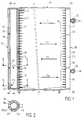
- the condenser of FIG. 1comprises a beam 10 formed of a multiplicity of flat tubes 12 between which are placed spacers 14 of generally wavy shape, forming heat exchange fins.
- the manifold 18is delimited by a side wall tubular 26, closed at both ends by two walls end 28 and 30 and provided with two internal partitions 32 and 34 arranged in selected places. Tubes 12 of beam communicate with the manifold 18 by suitable openings in the side wall 26.
- the first manifold 16includes a side wall tubular 36 of circular section, of diameter greater than the side wall 26, and provided with two open ends 38 and 40.
- annular transverse partitions 48 and 50are provided between walls 36 and 42 between places chosen to define annular compartments in which open the tubes 12 of the bundle, thanks to openings in the wall 36.
- the refrigerantcan thus circulate in the condenser, between input 22 and output 24, by a circuit in several passes, also called "multi-pass".
- the fluidwins firstly a compartment C1 defined in the manifold 18 between the wall 28 and the partition 32.
- the fluid refrigerantthen wins (arrow F1), through a part P1 of the bundle, an annular peripheral compartment C2 delimited between walls 36 and 42 and between wall 44 and the partition 48.
- the fluid gains (arrow F2)at across a part P2 of the beam, a compartment C3 delimited in the manifold 18 between the partitions 32 and 34.
- the fluid gains(arrow F3), through a part P4 of the harness, a compartment C4 delimited between the walls 36 and 42 and between partitions 48 and 50.
- the fluidthen enters the reservoir 20 (arrow F4), through an inlet opening 52 made in the wall lateral 42.
- the fluidthen leaves the reservoir via a outlet opening 54 (arrow F5) to gain a compartment C5 delimited between the side walls 36 and 42 and between the end wall 46 and the annular partition 50.
- the fluidthen wins (arrow F6), through part P4 of the bundle, a compartment C6 of the manifold 18, in which opens the outlet pipe 24.
- the fluidWhen the fluid enters the reservoir 20 through the opening 52, it is in the liquid phase and it is then sub-cooled during its passage through the P4 part of the beam, which is located downstream.
- the reservoir 20makes it possible to absorb variations in the volume of the refrigerant depending on expansion phenomena.
- the boxes manifolds 16 and 18respectively receive two tanks 20 and 82.
- these two tanksare of lower height than in the previous embodiment and they present two open ends, respectively 96 and 98, which are spaced from the respective end walls 44 and 86.
- the open ends 96 and 98are surrounded by two partitions annulars 100 and 102 obtained here by deformation of the walls reservoirs to form beads.
Landscapes
- Engineering & Computer Science (AREA)
- Physics & Mathematics (AREA)
- Mechanical Engineering (AREA)
- Thermal Sciences (AREA)
- General Engineering & Computer Science (AREA)
- Heat-Exchange Devices With Radiators And Conduit Assemblies (AREA)
- Air-Conditioning For Vehicles (AREA)
Description
Translated fromFrenchL'invention concerne un condenseur propre à faire partie d'uncircuit de réfrigération, par exemple d'une installation declimatisation pour véhicule automobile.The invention relates to a condenser capable of being part of arefrigeration circuit, for example an installation ofair conditioning for a motor vehicle.
Elle concerne plus particulièrement un condenseur pour uncircuit de réfrigération parcouru par un fluide frigorigène,comprenant un faisceau de tubes monté entre une premièreboíte collectrice, munie d'une paroi latérale tubulaire, etune seconde boíte collectrice, une entrée pour le fluidefrigorigène gazeux, une sortie pour le fluide frigorigènecondensé, ainsi qu'un réservoir propre à être traversé par lefluide frigorigène, communiquant, par l'intermédiaire d'aumoins une ouverture, avec une partie aval du faisceau, ducôté de la sortie du condenseur.It relates more particularly to a condenser for arefrigeration circuit traversed by a refrigerant,comprising a bundle of tubes mounted between a firstmanifold, provided with a tubular side wall, anda second manifold, an inlet for the fluidgaseous refrigerant, an outlet for the refrigerantcondensed, as well as a clean tank to be crossed by therefrigerant, communicating, throughminus an opening, with a downstream part of the beam, of theside of the condenser outlet.
Un condenseur de ce type est décrit dans le brevet US5 228 315.A condenser of this type is described in the US patent5,228,315.
Dans un circuit de réfrigération de ce type, le fluidefrigorigène est envoyé en phase vapeur surchauffée, sousl'action d'un compresseur, vers le condenseur où il estsuccessivement refroidi ou "désurchauffé", condensé en unephase liquide chaude, puis "sous-refroidi" en une phaseliquide froide.In a refrigeration circuit of this type, the fluidrefrigerant is sent in superheated vapor phase, underthe action of a compressor, towards the condenser where it issuccessively cooled or "desuperheated", condensed into ahot liquid phase, then "sub-cooled" in one phasecold liquid.
Le fluide frigorigène condensé et refroidi est ensuiteenvoyé, via un détendeur, vers un évaporateur où il échangede la chaleur avec un flux d'air à envoyer dans l'habitacledu véhicule. Dans l'évaporateur, le fluide frigorigène esttransformé en phase vapeur, tandis que le flux d'air estrefroidi pour fournir de l'air climatisé. Le fluide frigorigèneen phase vapeur quitte l'évaporateur pour regagnerensuite le compresseur et réaliser un nouveau cycle defonctionnement.The condensed and cooled refrigerant is thensent, via a pressure reducer, to an evaporator where it exchangesheat with an air flow to send into the passenger compartmentof the vehicle. In the evaporator, the refrigerant istransformed into vapor phase, while the air flow iscooled to provide air conditioning. The refrigerantin vapor phase leaves the evaporator to returnthen the compressor and carry out a new cycle ofoperation.
Dans le condenseur du brevet US 5 228 315, le réservoir estdisposé parallèlement et à l'extérieur de la première boítecollectrice, l'ensemble étant formé à partir d'une pièceextrudée.In the condenser of US Pat. No. 5,228,315, the tank isarranged parallel and outside the first boxcollector, the assembly being formed from a partextruded.
Cette solution connue a notamment pour inconvénient d'augmenterl'encombrement du condenseur, du fait que le réservoirest disposé à l'extérieur de la première boíte collectrice.This known solution notably has the drawback of increasingthe size of the condenser, because the tankis arranged outside the first manifold.
On connaít par ailleurs, d'après la Demande de brevetfrançais No 93 10325, un condenseur de ce type, dans lequelle réservoir est intégré au condenseur en étant fixé extérieurementà l'une des boítes collectrices.We also know from the Patent ApplicationFrench No 93 10325, a condenser of this type, in whichthe tank is integrated into the condenser by being fixed externallyto one of the manifolds.
Cette solution connue nécessite de prévoir des connexions etdes pattes de maintien entre le réservoir et la boítecollectrice, ce qui complique l'assemblage du condenseur,notamment les opérations de brasage.This known solution requires providing connections andholding tabs between the tank and the boxcollector, which complicates the assembly of the condenser,including brazing operations.
Par ailleurs, cette solution connue augmente l'encombrementdu condenseur, du fait que le réservoir est disposé àl'extérieur d'une des boítes collectrices.Furthermore, this known solution increases the size.of the condenser, because the tank is arranged tothe outside of one of the manifolds.
De plus, le réservoir extérieur constitue un élément enporte-à-faux qui génère des vibrations au niveau du condenseur.In addition, the external tank constitutes an element inoverhang that generates vibrations at the condenser.
L'invention a notamment pour but de surmonter les inconvénientsprécités.The object of the invention is in particular to overcome the drawbackscited above.
Elle propose en conséquence un condenseur du type défini enintroduction, dans lequel le réservoir est réalisé sous laforme d'un récipient présentant une paroi latérale tubulaireet coaxiale à la paroi latérale tubulaire de la premièreboíte collectrice, espacée à l'intérieur de celle-ci.It therefore proposes a condenser of the type defined inintroduction, in which the reservoir is produced under theshape of a container with a tubular side walland coaxial to the tubular side wall of the firstmanifold, spaced inside thereof.
Il n'est alors plus nécessaire de prévoir des connexions etdes pattes de maintien entre le réservoir et la boíte collectrice, du fait que le réservoir est logé à l'intérieurde la boíte collectrice.It is then no longer necessary to provide connections andholding tabs between the tank and the boxcollector, because the tank is housed insideof the manifold.
Il est ainsi possible de réaliser en une seule pièce leréservoir et la boíte collectrice, ce qui requiert desopérations d'assemblage moins complexes et moins longues.It is thus possible to carry out in one piece thetank and the manifold, which requiresless complex and less time consuming assembly operations.
Ceci simplifie notablement les opérations de brasage.This notably simplifies the brazing operations.
Le condenseur de l'invention a aussi pour avantage d'offrirun encombrement réduit, du fait que le réservoir extérieurest supprimé.The condenser of the invention also has the advantage of offeringreduced footprint, because the external tankis deleted.
En outre, il présente une meilleure tenue aux vibrations dufait qu'il supprime tout élément en porte-à-faux à l'extérieurde la boíte collectrice.In addition, it has better resistance to vibrations of thecauses it to remove any cantilevered elements outsideof the manifold.
Dans une première forme de réalisation de l'invention, descloisons transversales sont prévues entre la paroi latéralede la boíte collectrice et la paroi latérale du réservoirpour définir des compartiments périphériques communiquantavec des parties différentes du faisceau de tubes pourpermettre une circulation multi-passe du fluide frigorigènedans le faisceau de tubes.In a first embodiment of the invention,transverse partitions are provided between the side wallof the manifold and the side wall of the tankto define peripheral compartments communicatingwith different parts of the tube bundle forallow multi-pass circulation of the refrigerantin the bundle of tubes.
Avantageusement, la paroi latérale du réservoir comprend uneouverture pour l'entrée du fluide frigorigène provenant d'uncompartiment périphérique et une sortie pour l'évacuation dufluide frigorigène condensé vers un second compartimentpériphérique, lequel communique avec la sortie du condenseurau travers d'une partie du faisceau.Advantageously, the side wall of the tank comprises aopening for the entry of refrigerant from aperipheral compartment and an outlet for the evacuation ofrefrigerant condensed to a second compartmentperipheral, which communicates with the condenser outputthrough part of the beam.
Ainsi, le fluide frigorigène condensé traverse le réservoiret quitte ensuite le condenseur après avoir traversé unepartie du faisceau.Thus, the condensed refrigerant passes through the tankand then leaves the condenser after going through apart of the beam.
En variante, le réservoir comprend une ouverture d'extrémitéfaisant communiquer l'intérieur du réservoir avec un compartimentqui est prévu dans la première boíte collectrice et qui communique avec la sortie du condenseur, cette sortieétant prévue sur la première boíte collectrice.Alternatively, the reservoir includes an end openingcommunicating the interior of the tank with a compartmentwhich is provided in the first manifold andwhich communicates with the condenser output, this outputbeing provided on the first manifold.
Dans cette première forme de réalisation de l'invention, lescloisons transversales sont annulaires et les compartimentspériphériques ont également une section de forme annulaire.In this first embodiment of the invention, thetransverse partitions are annular and the compartmentsperipherals also have an annular section.
Dans une autre forme de réalisation de l'invention, la paroilatérale tubulaire du réservoir s'étend sur une partie de lapremière boíte collectrice et débouche sur une autre partiede la première boíte collectrice par une extrémité ouverte,une cloison annulaire étant prévue entre la boíte latérale dela première boíte collectrice et la paroi latérale duréservoir au niveau de l'extrémité ouverte de cette dernière.In another embodiment of the invention, the walltubular side of the tank extends over part of thefirst manifold and leads to another partof the first manifold by an open end,an annular partition being provided between the side box ofthe first manifold and the side wall of thetank at the open end of the latter.
Ainsi, la paroi latérale du réservoir s'étend seulement surune partie de la hauteur de la première boíte collectrice.Thus, the side wall of the tank extends only overpart of the height of the first manifold.
La seconde boíte collectrice est normalement dépourvue deréservoir et il est alors avantageux que l'entrée et lasortie du condenseur soient prévues sur cette seconde boítecollectrice.The second manifold is normally devoid oftank and then it is advantageous that the inlet and thecondenser outlet are provided on this second boxcollector.
Dans une autre forme de réalisation de l'invention, laseconde boíte collectrice loge également un second réservoirqui communique, par l'intermédiaire d'au moins une ouverture,avec une partie aval du faisceau, du côté de la sortie ducondenseur.In another embodiment of the invention, thesecond manifold also houses a second tankwhich communicates, via at least one opening,with a downstream part of the beam, on the exit side of thecondenser.
De préférence, la seconde boíte collectrice comprend uneparoi latérale tubulaire, tandis que le second réservoircomprend également une paroi latérale espacée au moins enpartie de la paroi latérale de la boíte collectrice, descloisons transversales étant prévues entre la paroi latéralede la seconde boíte collectrice et la paroi latérale dusecond réservoir pour définir des compartiments périphériquescommuniquant avec des parties différentes du faisceau pourpermettre une circulation multi-passe du fluide frigorigènedans le faisceau de tubes.Preferably, the second manifold includes atubular side wall, while the second tankalso includes a side wall spaced at least inpart of the side wall of the manifold,transverse partitions being provided between the side wallof the second manifold and the side wall of thesecond tank to define peripheral compartmentscommunicating with different parts of the beam toallow multi-pass circulation of the refrigerantin the bundle of tubes.
De préférence, la paroi latérale du second réservoir esttubulaire et coaxiale à la paroi latérale tubulaire de laseconde boíte collectrice, les cloisons transversales étantannulaires et les compartiments périphériques ayant égalementune section de forme annulaire.Preferably, the side wall of the second tank istubular and coaxial to the tubular side wall of thesecond manifold, the transverse partitions beingring and peripheral compartments also havingan annular section.
Selon une autre caractéristique de l'invention, la paroilatérale du second réservoir comporte une ouverture faisantcommuniquer l'intérieur du réservoir avec un compartimentpériphérique de la seconde boíte collectrice, dans lequeldébouche la sortie du condenseur.According to another characteristic of the invention, the wallside of the second tank has an openingcommunicating the interior of the tank with a compartmentperipheral of the second manifold, in whichopens the condenser outlet.
Dans une autre variante de réalisation, le premier réservoiret le second réservoir ont des extrémités ouvertes respectivesqui débouchent dans deux compartiments d'extrémité formésrespectivement dans la première boíte collectrice et laseconde boíte collectrice, ces deux compartiments d'extrémitécommuniquant entre eux par une partie des tubes du faisceau.In another alternative embodiment, the first tankand the second tank have respective open endswhich open into two formed end compartmentsrespectively in the first manifold and thesecond manifold, these two end compartmentscommunicating with each other through part of the bundle tubes.
Cette variante de réalisation offre l'avantage de séparer,dès la première passe du fluide frigorigène, les phasesliquide et vapeur afin d'améliorer les performances ducondenseur.This alternative embodiment offers the advantage of separating,from the first pass of the refrigerant, the phasesliquid and vapor to improve the performance of thecondenser.
Dans la description qui suit, faite seulement à titred'exemple, on se réfère aux dessins annexés, sur lesquels :
- la figure 1 est une vue en élévation et en coupe partielled'un condenseur selon une première forme de réalisation del'invention;
- la figure 2 est une vue en coupe selon l'une ou l'autre desdeux lignes II-II de la figure 1;
- la figure 3 est une vue partielle analogue à celle de lafigure 1 pour une variante de réalisation;
- la figure 4 est une vue en élévation du réservoir ducondenseur de la figure 3;
- la figure 5 est une vue de dessus du réservoir de lafigure 4;
- la figure 6 est un détail à échelle agrandie et en coupe duréservoir de la figure 4;
- la figure 7 est une vue partielle en coupe d'un condenseurselon une forme de réalisation non conforme à l'inventiontelle que revendiquée;
- la figure 8 est une vue en coupe selon l'une ou l'autre desdeux lignes VIII-VIII de la figure 7;
- la figure 9 est une vue partielle en coupe d'un condenseurselon une seconde forme de réalisation de l'invention;
- la figure 10 est une vue en coupe selon la ligne X-X de lafigure 9;
- la figure 11 est une vue en élévation et partiellement encoupe d'un condenseur selon une troisième forme de réalisationde l'invention;
- la figure 12 est une vue en coupe selon la ligne XII-XII dela figure 11;
- la figure 13 est une vue en coupe selon la ligne XIII-XIIIde la figure 10;
- la figure 14 est une vue analogue à celle de la figure 11dans une variante de réalisation; et
- la figure 15 est une vue en élévation et en coupe partielled'un condenseur selon une variante de réalisation de lafigure 1.
- Figure 1 is an elevational view in partial section of a condenser according to a first embodiment of the invention;
- Figure 2 is a sectional view along one or the other of the two lines II-II of Figure 1;
- Figure 3 is a partial view similar to that of Figure 1 for an alternative embodiment;
- Figure 4 is an elevational view of the condenser tank of Figure 3;
- Figure 5 is a top view of the tank of Figure 4;
- Figure 6 is a detail on an enlarged scale and in section of the tank of Figure 4;
- Figure 7 is a partial sectional view of a condenser according to an embodiment not according to the invention as claimed;
- Figure 8 is a sectional view along one or the other of the two lines VIII-VIII of Figure 7;
- Figure 9 is a partial sectional view of a condenser according to a second embodiment of the invention;
- Figure 10 is a sectional view along line XX of Figure 9;
- Figure 11 is an elevational view partially in section of a condenser according to a third embodiment of the invention;
- Figure 12 is a sectional view along line XII-XII of Figure 11;
- Figure 13 is a sectional view along line XIII-XIII of Figure 10;
- Figure 14 is a view similar to that of Figure 11 in an alternative embodiment; and
- FIG. 15 is a view in elevation and in partial section of a condenser according to an alternative embodiment of FIG. 1.
Le condenseur de la figure 1 comprend un faisceau 10 forméd'une multiplicité de tubes plats 12 entre lesquels sontplacés des intercalaires 14 de forme générale ondulée,formant ailettes d'échange de chaleur.The condenser of FIG. 1 comprises a
Le faisceau 10 est monté entre une première boíte collectrice16 et une seconde boíte collectrice 18 de forme tubulaire àsection circulaire et d'axes parallèles. La boíte collectrice16 loge intérieurement un réservoir 20, tandis que la boítecollectrice 18 est munie d'une tubulure d'entrée 22 pourl'admission d'un fluide frigorigène sous forme de vapeursurchauffée et d'une tubulure de sortie 24 pour l'évacuationdu fluide frigorigène sous forme de phase liquide refroidie.En traversant l'échangeur de chaleur, le fluide frigorigèneest successivement refroidi ou "désurchauffé", condensé enphase liquide chaude, puis "sous-refroidi" en phase liquidefroide, et cela par échange thermique avec un flux d'airbalayant le faisceau 10.The
La boíte collectrice 18 est délimitée par une paroi latéraletubulaire 26, fermée à ses deux extrémités par deux paroisd'extrémité 28 et 30 et munie de deux cloisons internes 32 et34 disposées en des endroits choisis. Les tubes 12 dufaisceau communiquent avec la boíte collectrice 18 par desouvertures appropriées ménagées dans la paroi latérale 26.The manifold 18 is delimited by a side walltubular 26, closed at both ends by two
La première boíte collectrice 16 comprend une paroi latéraletubulaire 36 de section circulaire, de diamètre supérieur àla paroi latérale 26, et munie de deux extrémités ouvertes 38et 40.The
Le réservoir 20 comprend une paroi latérale 42 de formetubulaire de section circulaire et logée à l'intérieur de laparoi latérale 36. La paroi 42 s'étend sur sensiblement toutela hauteur de la première boíte collectrice (telle que définie entre ses extrémités 38 et 40) et cette paroilatérale 42 est fermée par deux parois d'extrémité 44 et 46qui se poursuivent jusqu'à l'intérieur de la paroi latérale36 pour fermer en même temps les extrémités 38 et 40 de laboite collectrice 16.The
Par ailleurs, deux cloisons transversales annulaires 48 et 50sont prévues entre les parois 36 et 42 entre des endroitschoisis pour définir des compartiments annulaires danslesquels débouchent les tubes 12 du faisceau, grâce à desouvertures ménagées dans la paroi 36.In addition, two annular
Le fluide frigorigène peut ainsi circuler dans le condenseur,entre l'entrée 22 et la sortie 24, par un circuit en plusieurspasses, encore appelé "multi-passe". Le fluide gagnetout d'abord un compartiment C1 défini dans la boíte collectrice18 entre la paroi 28 et la cloison 32. Le fluidefrigorigène gagne ensuite (flèche F1), au travers d'unepartie P1 du faisceau, un compartiment périphérique annulaireC2 délimité entre les parois 36 et 42 et entre la paroi 44 etla cloison 48. Ensuite, le fluide gagne (flèche F2), autravers d'une partie P2 du faisceau, un compartiment C3délimité dans la boíte collectrice 18 entre les cloisons 32et 34. De là, le fluide gagne (flèche F3), au travers d'unepartie P4 du faisceau, un compartiment C4 délimité entre lesparois 36 et 42 et entre les cloisons 48 et 50.The refrigerant can thus circulate in the condenser,between
Le fluide pénètre ensuite dans le réservoir 20 (flèche F4),au travers d'une ouverture d'entrée 52 ménagée dans la paroilatérale 42. Le fluide quitte ensuite le réservoir par uneouverture de sortie 54 (flèche F5) pour gagner un compartimentC5 délimité entre les parois latérales 36 et 42 et entrela paroi d'extrémité 46 et la cloison annulaire 50. Le fluidegagne ensuite (flèche F6), au travers d'une partie P4 dufaisceau, un compartiment C6 de la boíte collectrice 18, danslequel débouche la tubulure de sortie 24.The fluid then enters the reservoir 20 (arrow F4),through an
Lorsque le fluide pénètre dans le réservoir 20 par l'ouverture52, il est en phase liquide et il est ensuite sous-refroidi lors de son passage par la partie P4 du faisceau,qui est située vers l'aval. Le réservoir 20 permet d'absorberles variations du volume du fluide réfrigérant en fonctiondes phénomènes de dilatation.When the fluid enters the
Dans la forme de réalisation de la figure 1, les cloisonstransversales 48 et 50 sont formées par des éléments annulairesrapportés entre la paroi latérale 36 de la boíte collectrice16 et la paroi latérale 42 du réservoir 20.In the embodiment of Figure 1, the partitionstransverse 48 and 50 are formed by annular elementsreported between the
Dans la forme de réalisation des figures 3 à 6, auxquelles onse réfère maintenant, les cloisons transversales annulairessont obtenues par déformation localisée de la paroi latérale42 du réservoir, de manière à définir des bourrelets annulairespériphériques 56 et 58 qui viennent en appui contre laface interne de la paroi latérale 36.In the embodiment of Figures 3 to 6, which arenow refers to the annular transverse bulkheadsare obtained by localized deformation of the
On se réfère maintenant aux figures 7 et 8 qui concernent uncondenseur de structure très proche de celle décrite précédemmentmais non conforme à l'invention.We now refer to Figures 7 and 8 which relate to acondenser with a structure very close to that described abovebut not in accordance with the invention.
Dans ce condenseur, le réservoir 20 comprend uneparoi latérale 60 de forme incurvée dont les génératricessont parallèles à celles de la paroi tubulaire 36 de la boítecollectrice 16. La paroi 60 a une section en forme de Uterminée par deux bords parallèles 62 et 64 (figure 8) qui seraccordent à deux génératrices 66 et 68, diamétralementopposées, de la paroi latérale 36. La paroi 60 délimite ainsià l'intérieur de la boíte collectrice 16 un volume dont lasection transversale ressemble à celle d'un croissant et danslequel débouchent les tubes du faisceau. Cet espace estdivisé par deux cloisons transversales 70 et 72, placées auxmêmes endroits que les cloisons 48 et 50 ou que les cloisons56 et 58, pour définir les compartiments C2, C4 et C5. Lescloisons 70 et 72 ont une forme de croissant et les compartimentsC2, C4 et C5 ont également une section en forme decroissant. Par ailleurs, la paroi 60 est munie de deuxouvertures 52 et 54 analogues à celles décrites précédemment.In this condenser, the
Le fonctionnement du condenseur des figures 7 et 8 estanalogue à celui des figures 1 et 2 ou à celui des figures 3à 6.The operation of the condenser of Figures 7 and 8 issimilar to that of Figures 1 and 2 or that of Figures 3to 6.
On se réfère maintenant aux figures 9 et 10 pour décrire uneautre forme de réalisation de l'invention qui s'apparente àcelles décrites précédemment.We now refer to Figures 9 and 10 to describe aanother embodiment of the invention which is akin tothose described above.
Le réservoir 20 comprend ici une paroi latérale 74 de formetubulaire circulaire, située coaxialement à l'intérieur dela paroi latérale 36 de la boíte collectrice 16. Dans cetteforme de réalisation, la paroi 74 s'étend sur une partieseulement de la hauteur de la boíte collectrice 16, dansl'exemple sur sensiblement la moitié de cette hauteur.The
La paroi tubulaire 74 présente une extrémité ouverte 76fermée par une paroi d'extrémité 44 analogue à celle décriteprécédemment. Elle présente en outre une extrémité ouverte 78qui débouche directement dans une seconde partie de la boítecollectrice 16, laquelle est en communication directe avecles tubes des parties P3 et P4 du faisceau. Une cloisonannulaire 80 est prévue entre la paroi latérale 36 de laboíte collectrice et la paroi latérale 74 du réservoir, auniveau de son extrémité ouverte 78. Ainsi, un compartimentC2, analogue à celui décrit précédemment, est délimité entreles parois latérales 36 et 74, la paroi d'extrémité 44 et lacloison annulaire 80.The
Le fonctionnement du condenseur des figures 9 et 10 estanalogue à celui des formes de réalisation décrites précédemment.The operation of the condenser of FIGS. 9 and 10 issimilar to that of the embodiments described above.
Dans la forme de réalisation des figures 11 à 13, auxquelleson se réfère maintenant, la boíte collectrice 16 est munied'un réservoir 20 analogue à celui décrit précédemment enréférence à la figure 3. Toutefois, la boíte collectrice 16et le réservoir 20 ont des sections plus faibles que dans laforme de réalisation précédente.In the embodiment of Figures 11 to 13, whichwe refer now, the manifold 16 is provideda
En effet, la seconde boíte collectrice 18 loge également unsecond réservoir 82 qui s'étend sur toute la hauteur de laseconde boíte collectrice.Indeed, the
Le réservoir 82 comprend une paroi latérale tubulaire 84 desection circulaire, qui est logée coaxialement dans la paroitubulaire 26. La paroi 84 est fermée par deux parois d'extrémité86 et 88 qui jouent le rôle des parois d'extrémité 28 et30 décrites précédemment.The
Par ailleurs, la paroi 84 est pliée pour former deux bourreletsannulaires 90 et 92 formant cloison transversale etdisposés aux mêmes endroits que les cloisons 32 et 34, commedans les formes de réalisation décrites précédemment enréférence aux figures 1 à 8.Furthermore, the
Il en résulte que la boíte collectrice 18 comporte troiscompartiments C1, C3 et C6 qui sont ici de configurationannulaire.It follows that the manifold 18 has threecompartments C1, C3 and C6 which are here of configurationannular.
La paroi latérale 84 est pourvue d'une ouverture 94 faisantcommuniquer l'intérieur du réservoir 80 avec le compartimentpériphérique C6 de la boíte collectrice 18, dans lequeldébouche la sortie 24 du condenseur.The
Dans la forme de réalisation des figures 11 à 13, les boítescollectrices 16 et 18 ont sensiblement le même diamètre, quemême que les réservoirs 20 et 82. Ces deux derniers permettentde compenser les variations de volume du fluide frigorigèneà l'état liquide.In the embodiment of Figures 11 to 13, the boxesmanifolds 16 and 18 have substantially the same diameter assame as
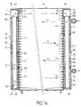
On se réfère maintenant à la forme de réalisation de lafigure 14 qui s'apparente à celle des figures 11 à 13.We now refer to the embodiment of theFigure 14 which is similar to that of Figures 11 to 13.
Comme dans la forme de réalisation précédente, les boítescollectrices 16 et 18 reçoivent respectivement deux réservoirs20 et 82.As in the previous embodiment, the boxesmanifolds 16 and 18 respectively receive two
Toutefois, ces deux réservoirs sont de hauteur plus faibleque dans la forme de réalisation précédente et ils présententdeux extrémités ouvertes, respectivement 96 et 98, qui sontespacées des parois d'extrémité respectives 44 et 86. Lesextrémités ouvertes 96 et 98 sont entourées par deux cloisonsannulaires 100 et 102 obtenues ici par déformation des paroisdes réservoirs pour former des bourrelets.However, these two tanks are of lower heightthan in the previous embodiment and they presenttwo open ends, respectively 96 and 98, which arespaced from the
L'extrémité ouverte 96 du premier réservoir 20 débouche ainsidans un compartiment C7, lequel communique par une partie P5du faisceau (dans l'exemple formé de trois tubes) avec uncompartiment C8 formé en partie supérieure de la boítecollectrice 18 et communiquant avec l'intérieur du réservoir82 par l'extrémité ouverte 98. Cette forme de réalisationpermet de séparer, à la fin de la troisième passe (partie P3;flèche F3) les phases liquide et vapeur pour améliorer lesperformances du condenseur.The
En effet, si de la vapeur se trouve introduite dans leréservoir 20, cette vapeur a tendance à s'élever pour gagnerle compartiment C7, puis le compartiment C8 au travers de lapartie P5 du faisceau, comme montré par la flèche F7. Cettevapeur se trouve alors condensée et parvient à l'étatcondensé au compartiment C8 pour ensuite gagner l'intérieurdu réservoir 82 et être évacuée du condenseur par l'ouverture94 du réservoir 82 et, de là, par la sortie 24.Indeed, if steam is introduced into the
Le condenseur représenté à la figure 15 s'apparente à celuide la figure 1, si ce n'est que deux cloisons transversales104, 106, sont prévues entre la paroi latérale 36 de la boítecollectrice 16 et la paroi latérale 42 du réservoir. Cependant,contrairement à la forme de réalisation de la figure 1,il n'est prévu aucune ouverture au travers de cette paroilatérale. Deux compartiments C2 et C4 sont ainsi définisentre la paroi latérale du réservoir et la paroi latérale dela boíte collectrice.The condenser represented in figure 15 is similar to thatof figure 1, if it is only two
Comme on le voit sur la figure 15, la cloison transversale106 est située près de la paroi d'extrémité 46. Le réservoir comprend ainsi une ouverture d'extrémité 108 qui faitcommuniquer l'intérieur du réservoir avec un compartiment C6prévu en partie inférieure de la boíte collectrice 16.As seen in Figure 15, the
Dans cette forme de réalisation, la sortie 24 du condenseurest prévue sur la boíte collectrice 16 et communique directementavec le compartiment C6. Le fluide frigorigène entre parl'entrée 22 dans la seconde boíte collectrice 18, parcourtensuite les tubes du faisceau, comme indiqué par les flèchesF1, F2, F3, F4 et F5, pour gagner le compartiment C6 avant dequitter le condenseur par la sortie 24 prévue sur la premièreboíte collectrice 16.In this embodiment, the
L'invention n'est pas limitée aux formes de réalisationdécrites précédemment à titre d'exemple et s'étend à d'autresvariantes, notamment en ce qui concerne la dispositionrelative et le nombre des tubes formant les différentesparties du faisceau.The invention is not limited to the embodimentsdescribed above by way of example and extends to othervariants, especially with regard to the layoutrelative and the number of tubes forming the differentparts of the beam.
L'invention trouve une application particulière aux installationsde climatisation des véhicules automobiles.The invention finds a particular application in installationsmotor vehicle air conditioning.
Claims (14)
- A condenser for a refrigerating circuit throughwhich a refrigerant fluid flows, comprising a bundle(10) of tubes (12) which are connected between afirst header (16) which has a tubular lateral wall(36), and a second header (18), an inlet (22) for therefrigerant fluid in the gaseous state, an outlet(24) for the condensed refrigerant fluid, and areservoir (20) arranged for the refrigerant fluid topass through it and communicating, through at leastone aperture (52, 54), with a downstream part (P3,P4) of the bundle on the same side as the outlet (24)of the condenser, characterised in that the reservoir(20) is made in the form of a receptacle having alateral wall (42) which is tubular and coaxial withthe tubular lateral wall (36) of the first header(16), from which it is spaced within the latter.
- A condenser according to Claim 1, characterisedin that transverse partitions (48, 50; 56, 58; 70,72; 104, 106) are arranged between the lateral wall(36) of the header and the lateral wall (42) of thereservoir (20) so as to define peripheralcompartments (C2, C4, C5) which are in communicationwith various parts (P1, P2, P3, P4) of the bundle,whereby to enable the refrigerant fluid to flow inmultiple passes within the bundle of tubes.
- A condenser according to Claim 2, characterisedin that the lateral wall (42) of the reservoir (20)includes an aperture for admission of the refrigerantfluid coming from a peripheral compartment (C4), andan outlet (54) for evacuation of the condensed refrigerant fluid to another peripheral compartment(C5), which is in communication with the outlet (24)of the condenser through a part (P4) of the bundle(10) .
- A condenser according to Claim 2, characterisedin that the reservoir terminates in an opening (108)which puts the interior of the reservoir intocommunication with a compartment (C6) arranged withinthe first header (16) and communicating with theoutlet (26), and in that the said outlet (26) isarranged on the first header (16).
- A condenser according to one of Claims 2 to 4,characterised in that the transverse partitions (48,50; 56, 58) are annular, and in that the peripheralcompartments (C2, C4, C5) also have an annular crosssection.
- A condenser according to Claim 5, characterisedin that the transverse partitions are defined byannular elements (48, 50; 104, 106) which aremounted between the lateral wall (36) of the firstheader (16) and the lateral wall (42) of thereservoir (20).
- A condenser according to Claim 5, characterisedin that the transverse partitions are obtained bydeformation of the lateral wall (42) of the reservoir(20); whereby to define annular beads (56, 58).
- A condenser according to Claim 1, characterisedin that the tubular lateral wall (74) of thereservoir (20) extends over part of the first header(16), being open in another part of the first header(16) through an open end (78), an annular partition(80) being arranged between the lateral wall (36) of the first header (16) and the lateral wall (74) ofthe reservoir (20), at the level of the open end (78)of the latter.
- A condenser according to one of Claims 1 to 8,characterised in that the second header (18) has noreservoir, and in that the inlet (22) and outlet (24)of the condenser are arranged on the said secondheader.
- A condenser according to one of Claims 1 to 8,characterised in that the second header (18) furthercontains a reservoir (82) which is in communication,through at least one aperture (94), with a downstreampart (P4) of the bundle (10) on the same side as theoutlet (24) of the condenser.
- A condenser according to Claim 10, characterisedin that the second header (18) includes a tubularlateral wall (26), and in that the second reservoir(82) includes a lateral wall (84) which is spaced atleast partly from the lateral wall (26) of theheader, and in that transverse partitions (90, 92)are arranged between the lateral wall (26) of thesecond header (18) and the lateral wall (84) of thesecond reservoir (82), so as to define peripheralcompartments (C1, C3, C6) which are in communicationwith various parts (P1, P2, P3, P4) of the bundle,whereby to enable the refrigerant fluid to flow inmultiple passes within the bundle of tubes.
- A condenser according to Claim 11, characterisedin that the lateral wall (84) of the second reservoir(82) is tubular and coaxial with the tubular lateralwall (26) of the second header (18), in that thetransverse partitions (90, 92) are annular, and in that the peripheral compartments (C1, C3, C6) alsohave an annular cross section.
- A condenser according to Claim 11 or Claim 12,characterised in that the lateral wall (84) of thesecond reservoir (82) has an aperture (94) which putsthe interior of the reservoir into communication witha peripheral compartment (C6) of the second header(18) into which the outlet (24) of the condenser isopen.
- A condenser according to one of Claims 10 to 13,characterised in that the first reservoir (20) andthe second reservoir (82) have respective open ends(96, 98) which are open into two end compartments(C7, C8) formed in the first header (16) and secondheader (18) respectively, and in that the said twoend compartments (C7, C8) are in communication witheach other through a part (P5) of the tubes in thebundle.
Applications Claiming Priority (3)
| Application Number | Priority Date | Filing Date | Title |
|---|---|---|---|
| FR9507599AFR2735851B1 (en) | 1995-06-23 | 1995-06-23 | CONDENSER WITH INTEGRATED TANK FOR AIR CONDITIONING SYSTEM OF MOTOR VEHICLE |
| FR9507599 | 1995-06-23 | ||
| PCT/FR1996/000948WO1997001067A1 (en) | 1995-06-23 | 1996-06-19 | Condenser with a built-in receiver for a motor vehicle air conditioning unit |
Publications (2)
| Publication Number | Publication Date |
|---|---|
| EP0774102A1 EP0774102A1 (en) | 1997-05-21 |
| EP0774102B1true EP0774102B1 (en) | 2001-01-10 |
Family
ID=9480351
Family Applications (1)
| Application Number | Title | Priority Date | Filing Date |
|---|---|---|---|
| EP96922953AExpired - LifetimeEP0774102B1 (en) | 1995-06-23 | 1996-06-19 | Condenser with a built-in receiver for a motor vehicle air conditioning unit |
Country Status (8)
| Country | Link |
|---|---|
| US (1) | US5896754A (en) |
| EP (1) | EP0774102B1 (en) |
| KR (1) | KR970705730A (en) |
| CN (1) | CN1157035A (en) |
| BR (1) | BR9606477A (en) |
| DE (1) | DE69611507T2 (en) |
| FR (1) | FR2735851B1 (en) |
| WO (1) | WO1997001067A1 (en) |
Cited By (1)
| Publication number | Priority date | Publication date | Assignee | Title |
|---|---|---|---|---|
| US7003978B2 (en) | 2003-12-12 | 2006-02-28 | Calsonickansei North America, Inc. | Service cartridge for a receiver in a condenser system |
Families Citing this family (28)
| Publication number | Priority date | Publication date | Assignee | Title |
|---|---|---|---|---|
| FR2758876B1 (en)* | 1997-01-27 | 1999-04-02 | Valeo Thermique Moteur Sa | CONDENSER PROVIDED WITH A REFRIGERANT FLUID TANK FOR AIR CONDITIONING CIRCUIT |
| KR100264815B1 (en)* | 1997-06-16 | 2000-09-01 | 신영주 | Multi-stage air and liquid separable type condenser |
| FR2766559B1 (en)* | 1997-07-24 | 1999-10-22 | Valeo Thermique Moteur Sa | CONDENSER WITH INTEGRATED DOUBLE TANK, ESPECIALLY FOR A MOTOR VEHICLE AIR CONDITIONING CIRCUIT |
| JP3801348B2 (en)* | 1997-07-28 | 2006-07-26 | 株式会社ヴァレオサーマルシステムズ | Receiver tank |
| FR2769361B1 (en) | 1997-10-02 | 1999-12-24 | Valeo Thermique Moteur Sa | COLLECTOR BOX WITH INTEGRATED TANK FOR HEAT EXCHANGER, PARTICULARLY FOR A REFRIGERATION CONDENSER |
| FR2799821B1 (en)* | 1999-09-28 | 2002-03-29 | Valeo Thermique Moteur Sa | CONDENSER COMPRISING A RESERVOIR FIXED IN A REMOVABLE AND SEALED MANNER ON A BASE |
| US6360560B1 (en)* | 1999-12-01 | 2002-03-26 | Visteon Global Technologies, Inc. | Condenser with integral receiver dryer |
| DE10155001A1 (en)* | 2001-11-08 | 2003-05-22 | Behr Gmbh & Co | Refrigerant condenser |
| JP2003185296A (en)* | 2001-12-14 | 2003-07-03 | Sanden Corp | Heat exchanger |
| US6557373B1 (en)* | 2002-03-12 | 2003-05-06 | Newfield Technology Corporation | Apparatus for coupling a manifold block to a condenser manifold |
| US6622517B1 (en) | 2002-06-25 | 2003-09-23 | Visteon Global Technologies, Inc. | Condenser assembly having readily varied volumetrics |
| DE10339072A1 (en)* | 2003-08-26 | 2005-03-24 | Daimlerchrysler Ag | Heat exchanger with integrated inlet and outlet |
| DE10345921A1 (en)* | 2003-10-02 | 2005-05-12 | Modine Mfg Co | Condenser and receiver for desiccant |
| BRPI0514699B1 (en) | 2004-08-29 | 2019-04-09 | Huawei Technologies Co., Ltd. | DOUBLE HOMING IMPLEMENTATION EQUIPMENT METHOD, SYSTEM AND PART |
| JP4591960B2 (en)* | 2005-07-04 | 2010-12-01 | 日軽熱交株式会社 | Heat exchanger with receiver tank |
| JP4779641B2 (en)* | 2005-12-26 | 2011-09-28 | 株式会社デンソー | Combined heat exchanger |
| US20080023185A1 (en) | 2006-07-25 | 2008-01-31 | Henry Earl Beamer | Heat exchanger assembly |
| US7484555B2 (en) | 2006-07-25 | 2009-02-03 | Delphi Technologies, Inc. | Heat exchanger assembly |
| US20090173482A1 (en)* | 2008-01-09 | 2009-07-09 | Beamer Henry E | Distributor tube subassembly |
| KR101317377B1 (en)* | 2011-11-21 | 2013-10-22 | 현대자동차주식회사 | Condenser for vehicle |
| US9581397B2 (en) | 2011-12-29 | 2017-02-28 | Mahle International Gmbh | Heat exchanger assembly having a distributor tube retainer tab |
| FR3013436B1 (en)* | 2013-11-18 | 2018-12-07 | Valeo Systemes Thermiques | COLLECTOR FOR HEAT EXCHANGER |
| US10330358B2 (en)* | 2014-05-15 | 2019-06-25 | Lennox Industries Inc. | System for refrigerant pressure relief in HVAC systems |
| US9976785B2 (en) | 2014-05-15 | 2018-05-22 | Lennox Industries Inc. | Liquid line charge compensator |
| US10551099B2 (en) | 2016-02-04 | 2020-02-04 | Mahle International Gmbh | Micro-channel evaporator having compartmentalized distribution |
| US10663199B2 (en) | 2018-04-19 | 2020-05-26 | Lennox Industries Inc. | Method and apparatus for common manifold charge compensator |
| US10830514B2 (en) | 2018-06-21 | 2020-11-10 | Lennox Industries Inc. | Method and apparatus for charge compensator reheat valve |
| JP2020100256A (en)* | 2018-12-21 | 2020-07-02 | サンデン・オートモーティブクライメイトシステム株式会社 | Condenser, and air conditioner for vehicle |
Family Cites Families (13)
| Publication number | Priority date | Publication date | Assignee | Title |
|---|---|---|---|---|
| US2028458A (en)* | 1935-05-07 | 1936-01-21 | Karmazin Engineering Company | Refrigerating apparatus |
| US2105121A (en)* | 1935-05-31 | 1938-01-11 | Karmazin Engineering Company | Refrigerating apparatus |
| FR2491610B1 (en)* | 1980-10-02 | 1986-01-24 | Valeo | WATER BOX FORMING COLLECTOR CHAMBER AND EXPANSION CHAMBER FOR A HEAT EXCHANGER |
| FR2521277B1 (en)* | 1982-02-08 | 1987-07-24 | Valeo | HEAT EXCHANGER, PARTICULARLY FOR AN INTERNAL COMBUSTION ENGINE COOLING CIRCUIT |
| US5172758A (en)* | 1989-02-01 | 1992-12-22 | Sanden Corporation | Condenser with a built-in receiver |
| JPH0740943Y2 (en)* | 1989-02-03 | 1995-09-20 | サンデン株式会社 | Condenser with built-in liquid receiver |
| US4972683A (en)* | 1989-09-01 | 1990-11-27 | Blackstone Corporation | Condenser with receiver/subcooler |
| JP3013492B2 (en)* | 1990-10-04 | 2000-02-28 | 株式会社デンソー | Refrigeration apparatus, heat exchanger with modulator, and modulator for refrigeration apparatus |
| JP3044395B2 (en)* | 1990-12-28 | 2000-05-22 | 株式会社ゼクセル | Receiver dryer integrated condenser |
| US5186248A (en)* | 1992-03-23 | 1993-02-16 | General Motors Corporation | Extruded tank condenser with integral manifold |
| FR2709344B1 (en)* | 1993-08-27 | 1995-10-13 | Valeo Thermique Moteur Sa | Condenser for motor vehicle air conditioning system. |
| US5546761A (en)* | 1994-02-16 | 1996-08-20 | Nippondenso Co., Ltd. | Receiver-integrated refrigerant condenser |
| JP3243924B2 (en)* | 1994-04-01 | 2002-01-07 | 株式会社デンソー | Refrigerant condenser |
- 1995
- 1995-06-23FRFR9507599Apatent/FR2735851B1/ennot_activeExpired - Lifetime
- 1996
- 1996-06-19BRBR9606477Apatent/BR9606477A/ennot_activeIP Right Cessation
- 1996-06-19CNCN96190670Apatent/CN1157035A/enactivePending
- 1996-06-19DEDE69611507Tpatent/DE69611507T2/ennot_activeExpired - Lifetime
- 1996-06-19EPEP96922953Apatent/EP0774102B1/ennot_activeExpired - Lifetime
- 1996-06-19KRKR1019970701155Apatent/KR970705730A/ennot_activeWithdrawn
- 1996-06-19WOPCT/FR1996/000948patent/WO1997001067A1/ennot_activeApplication Discontinuation
- 1996-06-19USUS08/793,244patent/US5896754A/ennot_activeExpired - Lifetime
Cited By (1)
| Publication number | Priority date | Publication date | Assignee | Title |
|---|---|---|---|---|
| US7003978B2 (en) | 2003-12-12 | 2006-02-28 | Calsonickansei North America, Inc. | Service cartridge for a receiver in a condenser system |
Also Published As
| Publication number | Publication date |
|---|---|
| BR9606477A (en) | 1997-12-23 |
| KR970705730A (en) | 1997-10-09 |
| WO1997001067A1 (en) | 1997-01-09 |
| US5896754A (en) | 1999-04-27 |
| FR2735851A1 (en) | 1996-12-27 |
| MX9701401A (en) | 1997-05-31 |
| FR2735851B1 (en) | 1997-08-01 |
| DE69611507T2 (en) | 2001-04-26 |
| EP0774102A1 (en) | 1997-05-21 |
| CN1157035A (en) | 1997-08-13 |
| DE69611507D1 (en) | 2001-02-15 |
Similar Documents
| Publication | Publication Date | Title |
|---|---|---|
| EP0774102B1 (en) | Condenser with a built-in receiver for a motor vehicle air conditioning unit | |
| EP2118608B1 (en) | Heat exchanger and built-in assembly including such exchanger | |
| FR2709344A1 (en) | Condenser for motor vehicle air-conditioning installations | |
| FR2947041A1 (en) | Condenser for air-conditioning circuit of motor vehicle, has heat exchanging parts formed by two series of plates stacked in stacking direction, and fluid reserve formed partly by cavity that is directly formed in stack of plates | |
| EP2402694B1 (en) | Condenser, in particular for a car air-conditioning system and heat exchanger equipped with such a condenser | |
| FR2754887A1 (en) | REMOVABLE TANK CONDENSER FOR A REFRIGERATION CIRCUIT, PARTICULARLY A MOTOR VEHICLE | |
| WO2013001019A1 (en) | Heat exchanger, housing, and air-conditioning circuit including such an exchanger | |
| WO2012041441A2 (en) | Heat exchanger for a motor vehicle | |
| EP0798519A1 (en) | Condenser with integrated receiver for cooling circuit | |
| EP1459030A1 (en) | Circuit element for heat exchanger, in particular for motor vehicle and resulting heat exchanger | |
| EP1640676B1 (en) | Device combining internal heat exchanger and accumulator for an air conditioning circuit | |
| FR2823839A1 (en) | HEAT EXCHANGER | |
| FR2779809A1 (en) | CONDENSER WITH INTEGRATED RECEIVER FOR REFRIGERATION CYCLE | |
| EP0990106B1 (en) | Air conditioning condenser comprising a reservoir mounted on a base | |
| FR2747768A1 (en) | Condenser for refrigeration circuit in vehicle air conditioning | |
| EP1762803A1 (en) | Integrated assembly for air conditioning circuit with a supercritical refrigerant. | |
| WO1999067592A1 (en) | Motor vehicle heat exchanger and method for making same | |
| EP0984237B1 (en) | Multi-pass heat exchanger, particularly for motor vehicles | |
| WO2005031237A2 (en) | Circuit element for a heat exchanger, and heat exchanger thus obtained | |
| FR2755220A1 (en) | Refrigeration heat exchanger collector box with integral reservoir for automobile | |
| FR2746907A1 (en) | Condenser for motor vehicle air conditioning installation | |
| EP2072936B1 (en) | Unitary heat exchanger for air conditioning circuit | |
| WO2003071202A1 (en) | Liquid/vapour separator in an air-conditioning circuit | |
| FR2754886A1 (en) | Serpentine tube condenser for motor-vehicle air conditioning system | |
| FR2759447A1 (en) | Automobile air conditioner condenser |
Legal Events
| Date | Code | Title | Description |
|---|---|---|---|
| PUAI | Public reference made under article 153(3) epc to a published international application that has entered the european phase | Free format text:ORIGINAL CODE: 0009012 | |
| 17P | Request for examination filed | Effective date:19970127 | |
| AK | Designated contracting states | Kind code of ref document:A1 Designated state(s):DE ES GB IT SE | |
| 17Q | First examination report despatched | Effective date:19980622 | |
| GRAG | Despatch of communication of intention to grant | Free format text:ORIGINAL CODE: EPIDOS AGRA | |
| GRAG | Despatch of communication of intention to grant | Free format text:ORIGINAL CODE: EPIDOS AGRA | |
| GRAH | Despatch of communication of intention to grant a patent | Free format text:ORIGINAL CODE: EPIDOS IGRA | |
| GRAH | Despatch of communication of intention to grant a patent | Free format text:ORIGINAL CODE: EPIDOS IGRA | |
| GRAA | (expected) grant | Free format text:ORIGINAL CODE: 0009210 | |
| AK | Designated contracting states | Kind code of ref document:B1 Designated state(s):DE ES GB IT SE | |
| PG25 | Lapsed in a contracting state [announced via postgrant information from national office to epo] | Ref country code:SE Free format text:THE PATENT HAS BEEN ANNULLED BY A DECISION OF A NATIONAL AUTHORITY Effective date:20010110 Ref country code:IT Free format text:LAPSE BECAUSE OF FAILURE TO SUBMIT A TRANSLATION OF THE DESCRIPTION OR TO PAY THE FEE WITHIN THE PRESCRIBED TIME-LIMIT;WARNING: LAPSES OF ITALIAN PATENTS WITH EFFECTIVE DATE BEFORE 2007 MAY HAVE OCCURRED AT ANY TIME BEFORE 2007. THE CORRECT EFFECTIVE DATE MAY BE DIFFERENT FROM THE ONE RECORDED. Effective date:20010110 Ref country code:GB Free format text:LAPSE BECAUSE OF FAILURE TO SUBMIT A TRANSLATION OF THE DESCRIPTION OR TO PAY THE FEE WITHIN THE PRESCRIBED TIME-LIMIT Effective date:20010110 Ref country code:ES Free format text:THE PATENT HAS BEEN ANNULLED BY A DECISION OF A NATIONAL AUTHORITY Effective date:20010110 | |
| REF | Corresponds to: | Ref document number:69611507 Country of ref document:DE Date of ref document:20010215 | |
| GBV | Gb: ep patent (uk) treated as always having been void in accordance with gb section 77(7)/1977 [no translation filed] | Effective date:20010110 | |
| PLBE | No opposition filed within time limit | Free format text:ORIGINAL CODE: 0009261 | |
| STAA | Information on the status of an ep patent application or granted ep patent | Free format text:STATUS: NO OPPOSITION FILED WITHIN TIME LIMIT | |
| 26N | No opposition filed | ||
| PGFP | Annual fee paid to national office [announced via postgrant information from national office to epo] | Ref country code:DE Payment date:20150612 Year of fee payment:20 | |
| REG | Reference to a national code | Ref country code:DE Ref legal event code:R071 Ref document number:69611507 Country of ref document:DE |