EP0772319B1 - Method and system for sharing information between network managers - Google Patents
Method and system for sharing information between network managersDownload PDFInfo
- Publication number
- EP0772319B1 EP0772319B1EP96116268AEP96116268AEP0772319B1EP 0772319 B1EP0772319 B1EP 0772319B1EP 96116268 AEP96116268 AEP 96116268AEP 96116268 AEP96116268 AEP 96116268AEP 0772319 B1EP0772319 B1EP 0772319B1
- Authority
- EP
- European Patent Office
- Prior art keywords
- network
- database
- information
- network management
- sender
- Prior art date
- Legal status (The legal status is an assumption and is not a legal conclusion. Google has not performed a legal analysis and makes no representation as to the accuracy of the status listed.)
- Expired - Lifetime
Links
- 238000000034methodMethods0.000titleclaimsdescription261
- 230000008569processEffects0.000claimsdescription247
- 238000007726management methodMethods0.000claimsdescription199
- 238000012545processingMethods0.000claimsdescription64
- 238000001914filtrationMethods0.000claimsdescription23
- 238000013475authorizationMethods0.000claimsdescription19
- 238000004891communicationMethods0.000claimsdescription19
- 230000004044responseEffects0.000claimsdescription12
- 238000010586diagramMethods0.000description20
- 230000000694effectsEffects0.000description7
- 230000001360synchronised effectEffects0.000description7
- 230000009471actionEffects0.000description6
- 230000006870functionEffects0.000description6
- 230000008859changeEffects0.000description5
- 230000003993interactionEffects0.000description3
- 238000010276constructionMethods0.000description2
- 230000000977initiatory effectEffects0.000description2
- 238000012986modificationMethods0.000description2
- 230000004048modificationEffects0.000description2
- 238000012544monitoring processMethods0.000description2
- 230000005540biological transmissionEffects0.000description1
- 210000001072colonAnatomy0.000description1
- 238000004590computer programMethods0.000description1
- 238000013461designMethods0.000description1
- 238000011022operating instructionMethods0.000description1
- 230000008520organizationEffects0.000description1
- 230000002093peripheral effectEffects0.000description1
- 230000000644propagated effectEffects0.000description1
- 238000012546transferMethods0.000description1
- 230000001052transient effectEffects0.000description1
- 230000003442weekly effectEffects0.000description1
Images


Classifications
- H—ELECTRICITY
- H04—ELECTRIC COMMUNICATION TECHNIQUE
- H04L—TRANSMISSION OF DIGITAL INFORMATION, e.g. TELEGRAPHIC COMMUNICATION
- H04L41/00—Arrangements for maintenance, administration or management of data switching networks, e.g. of packet switching networks
- H04L41/04—Network management architectures or arrangements
- H04L41/042—Network management architectures or arrangements comprising distributed management centres cooperatively managing the network
- H—ELECTRICITY
- H04—ELECTRIC COMMUNICATION TECHNIQUE
- H04L—TRANSMISSION OF DIGITAL INFORMATION, e.g. TELEGRAPHIC COMMUNICATION
- H04L41/00—Arrangements for maintenance, administration or management of data switching networks, e.g. of packet switching networks
- H04L41/04—Network management architectures or arrangements
- H04L41/046—Network management architectures or arrangements comprising network management agents or mobile agents therefor
- H—ELECTRICITY
- H04—ELECTRIC COMMUNICATION TECHNIQUE
- H04Q—SELECTING
- H04Q3/00—Selecting arrangements
- H04Q3/0016—Arrangements providing connection between exchanges
- H04Q3/0062—Provisions for network management
- H—ELECTRICITY
- H04—ELECTRIC COMMUNICATION TECHNIQUE
- H04Q—SELECTING
- H04Q2213/00—Indexing scheme relating to selecting arrangements in general and for multiplex systems
- H04Q2213/13516—Indexing scheme relating to selecting arrangements in general and for multiplex systems agents or brokers - user, terminal etc., also OSI agent/managers
- H—ELECTRICITY
- H04—ELECTRIC COMMUNICATION TECHNIQUE
- H04Q—SELECTING
- H04Q2213/00—Indexing scheme relating to selecting arrangements in general and for multiplex systems
- H04Q2213/13535—Indexing scheme relating to selecting arrangements in general and for multiplex systems distributed systems - also domains in service creation
- H—ELECTRICITY
- H04—ELECTRIC COMMUNICATION TECHNIQUE
- H04Q—SELECTING
- H04Q2213/00—Indexing scheme relating to selecting arrangements in general and for multiplex systems
- H04Q2213/13547—Indexing scheme relating to selecting arrangements in general and for multiplex systems subscriber, e.g. profile, database, database access
Definitions
- the present inventionrelates to network management and, more particularly, to techniques for sharing information between network managers.
- the network management consolesare typically associated with a particular portion or subnet of the large network. These management consoles are separate in that there is no management interaction between the different network management consoles that are managing portions of the large network.
- US-A-5,317,568describes a data communication method and apparatus that allows communication in a distributed heterogeneous network.
- Communications managersreside in local processing environments and are responsible for interfacing local end users with the remainder of the heterogeneous network.
- Each communication managerreceives distribution units from end users, the distribution units being assigned various priority levels and levels of assurance.
- an adjacent communications manageris determined in accordance with a communications path to a destination for the distribution unit.
- the distribution unitis then configured according to a network protocol stack existing between the communications manager and the adjacent communications manager, and the distribution units are transmitted according to priority.
- Each communications managercan have any number of adjacent communications managers each communicating through different network protocol stacks. Also described is load distribution among a complex of processors that share common functions, as well as control of information flow between adjacent communications managers.
- the inventionis a technique for managing a network by sharing information between distributed network managers which manage a different portion of the network.
- the inventionenables network managers to cooperate with one another so as to share important network information between distributed network management stations.
- the important network information being sharedis information about certain changes in the state of critical network devices or changes in selected aspects of network topology.
- the network management performed by the distributed network management stationscan inform site managers not only of local network conditions but also about network conditions on other remote networks.
- a filtering operationis used to determine that portion of the network information deemed important to forward to another network management station.
- a database synchronization operationis also optionally provided so that databases of each network management station, which store topology information concerning the particular portion of the network, can be automatically synchronized.
- the inventioncan be implemented in numerous ways, including as a system, a method, or as a computer readable medium.
- an embodiment of the inventionincludes: a sending machine, a receiving machine, and a communication link connecting the sending machine and the receiving machine.
- the sending machineincludes at least: a first network manager for receiving event and trap information from agents associated with a first network and for managing the first network; an authorization list containing information indicating whether receiving machines are authorized to receive the event and trap information; and a sender process for receiving the event and trap information received by the first network manager.
- the receiving machineincludes at least: a second network manager for managing a second network; a receiver process for receiving the event and trap information; and a registration list for identifying sender machines to which the receiving machine is to connect to receive event and trap information.
- the sender processoperates to forward the event and trap information to the receiving machine if the authorization list authorizes the receiving machine to receive the event and trap information, and the receiver process forwards the event and trap information received from the sender process to the second network manager for processing thereof.
- the sender process of the network management systemmay also filter the event and trap information, and then forward the filtered event and trap information to the receiving machine if the authorization list authorizes the receiving machine to receive the even and trap information.
- the first network manager of the network management systemtypically maintains a first database and the second network manager maintains a second database. It is preferable that the sender process also receives a synchronization request from the receiver process and in response thereto generates a database trap for each record in the first database and then forwards the database traps to the receiver process, and that the receiver process receives the database traps forwarded from the sender process and then synchronize the second database to the first database in accordance with the database traps.
- another embodiment of the inventionincludes: a first network manager for managing a first network; a second network manager for managing a second network; and information sharing means for sharing information between the first network manager and the second network manager.
- the embodiment of the inventionmay further include filter means for filtering the information before being transferred to the second network manager, and/or synchronization means for automatically synchronizing topology information between first and second databases associated with the first and second network managers, respectively.
- an embodiment of the inventionincludes the operations of: connecting a receiver process associated with the second network to a sender process associated with the first network; receiving network management data for the first network at the sender process; forwarding the network management data from the sender process to the receiver process; and processing the network management data in the second network manager.
- the computer-implemented methodmay also include one or both of the operations of: filtering the network management data at the sender process to produce filtered data for the receiver process, and automatically synchronizing a second database associated with the second network manager to the first database associated with the first network manager.
- another embodiment of the inventionincludes the operations of: connecting a receiver process associated with the second network to a sender process associated with the first network; receiving network management data for the first network at the sender process; filtering the network management data at the sender process to produce filtered data for the receiver process; forwarding the filtered data from the sender process to the receiver process; and processing the filtered data in the second network manager.
- an embodiment of the inventionincludes a computer usable medium having computer readable code embodied therein to implement sharing of network management data between first and second network managers, the first network manager locally managing a first network and the second network manager locally managing a second network.
- the computer readable codeincludes: first computer readable program code devices configured to cause a computer to effect connecting a receiver process associated with the second network to a sender process associated with the first network; second computer readable program code devices configured to cause a computer to effect receiving network management data for the first network at the sender process; third computer readable program code devices configured to cause a computer to effect forwarding the network management data from the sender process to the receiver process; and fourth computer readable program code devices configured to cause a computer to effect processing the network management data in the second network manager.
- the computer readable codemay further include computer readable program code devices configured to cause a computer to effect filtering of the network management data at the sender process to produce filtered data which is then forwarded to the receiver process, and/or computer readable program code devices configured to cause a computer to effect synchronization of a second database maintained by the second network manager to a first database maintained by the first network manager.
- Advantages of the inventioninclude flexibility and efficiency.
- the inventionprovides flexibility because it allows for many configurations of a network management system utilizing the invention.
- the inventionprovides for improved efficiency in network operation and management by facilitating overall network management and enabling remote site managers to take corrective action to improve network performance by taking into consideration important network information about remote networks which impact performance of the local network.
- the present inventionprovides techniques for sharing information between network managers. Namely, the invention enables network managers to cooperate with one another so as to share important network information between network managers. More particularly, the invention operates to share information about certain changes in the state of critical network devices or changes in selected aspects of network topology between multiple network management stations.
- the important network informationis event and topology information.
- the network management performed by the distributed network managerscan inform site managers not only of local network conditions but also about network conditions on other remote networks.
- site managersare able to take corrective action to improve network performance by taking into consideration important networks information about remote networks which impact performance of the local network.
- Global or central managementis also facilitated by the invention in an efficient and flexible manner because distributed network managers can be configured in numerous ways with ease.
- a network managerrefers to an application program which executes on a computer to manage a network.
- the computer executing the application programis referred to as a network management console machine.
- a site manageris an end-user who monitors the network via a display screen associated with the network management console machine.
- the network management console machineprovides information to the site manager so that the site manager is able to take corrective action when necessary to improve operation of the network
- different network management console machinesare able to share network management information such that a site manager who primarily manages a local network can monitor or manage some or all of other remote networks.
- a receiving stationis a network management console machine with a receiver process executing thereon.
- a sending stationis a network management console machine with a sender process executing thereon.
- a network management console machinemay function as both a sending station and a receiving station, or as only a sending station, or as only a receiving station.
- a network management system in accordance with the inventionincludes at least one sending station and at least one receiving station.
- the particular distribution of the sender and receiver processes on the network management console machinesdepends on the desired network management configuration. Due to the flexibility of the invention, many network management configurations are possible, including a peer-to-peer relationship, a periphery-to-center relationship, and a center-to-periphery relationship.
- each network management console machineIn the peer-to-peer configuration, the network management console machines both send and receive event and topology information to each other.
- each network management console machineincludes both a sender process and a receiver process, and thus functions as both a receiving and sending station.
- An example of the peer-to-peer configurationis as follows.
- Company XYZhas separate network management (NM) console machines to manage regional networks.
- a network management station in San Franciscois responsible for managing a west coast region and a network management station in New York is responsible for managing an east coast region.
- the network administrator in New Yorkwants to know about all changes to XYZ's backbone network (routers, WAN link) and critical servers (financial database server) in the west coast region. Events are filtered by a sender process on the San Francisco machine on the basis of host name (selecting the servers) and component type (selecting the routers) and forwarded to the NM console machine in New York.
- the relevant elementsreside in a view on the San Francisco machine called "WestNet.”
- the receiver process on the New York machinewill place forwarded topology information under a view also called “WestNet” on the New York machine.
- the network management station in San Franciscoalso wants to receive this type of information from the NM console machine in New York.
- a receiver process on the San Francisco machineplaces forwarded topology information under a view called "EastNet,” mirroring the view name on the New York machine.
- the flow of event and topology informationis from distributed network management console machines to a central management console machine.
- a central management console machineFor example, an organization may have multiple network management console machines responsible for regional components of its large network while also having a central network management console machine that needs to display and monitor the global network topology and the state of critical devices.
- the flow of informationin this configuration, is one-directional, from the regional management console machines to the central management console machine.
- the sender processneed only be installed on the regional network management console machines while the receiver process only needs to run on the central network management console machine.
- a variation on the periphery-to-center configurationis also available wherein regional network management console machines have management responsibility for a type of network link (for example, X.25, Frame Relay, ISDN) or type of network device (routers, database servers, T1 links) for the large network.
- each network management console machinereceives topology and event information from other network management console machines about devices of a particular type that it is responsible for, in addition to managing its own regional network.
- the network management console machinesfunction as the "center" only for a particular type network link or type of network device.
- Both the sender and receiver processesare needed on each network management console machine in this configuration.
- the sender processis required to forward information that pertains to the types of devices the other network management console machines are interested in.
- the receiver processis needed in order to function as a receiving station to receive information about the particular device types the local network management console machine is managing for the large network.
- topology changes and eventsare propagated from one or more central network management console machines to distributed network management console machines in order to off-load responsibility for management of particular regions, type of network, or type of device.
- the central network management console machineruns the sender process but not the receiver process
- the peripheral management console machinesrun the receiver process but not the sender process.
- the network management systemsare capable of forwarding three types of information between the network management stations.
- the first type of informationis network management (NM) events (hereafter NM events or events).
- NM eventsare generated by agents in response to NM event requests from network managers when conditions specified by the event requests are satisfied. For example, an agent could generate an event when a device associated with the agent becomes unreachable.
- An agentis a process that collects data from the managed object and reports it to the manager in the form or responses or generation of events/traps.
- the second type of informationis a trap.
- a trapis an unsolicited event (i.e., an event not generated in response to NM event requests).
- a trapis a Simple Network Management Protocol (SNMP) linkDown trap.
- a linkDown trapis an unsolicited message sent to the manager by the agent and identifies the state of a physical or logical communication link/interface as down.
- the third type of informationis a NM database trap.
- a NM database trapis generated when a change to a network management database is made. For example, NM database traps occur when adding a new element to the database or when some attributes of an element change or when an element is deleted.
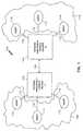
- FIG. 1is a block diagram of a network management system 100 according to the invention.
- the network management system 100includes a network management console machine A 102 and a network management console machine B 104.
- the network management console machines A and B 102, 104are interconnected by a communication link 106.
- Each of the network management console machines A and B 102, 104manages a separate portion of a large overall network (i.e., networks 108 and 114 respectively).
- certain network management informationis shared between the network management console machines 102 and 104 so that management of the overall network can be done more efficiently and effectively.
- the network management console machine A 102manages a network 108.
- the network 108includes numerous agents 110 which are coupled to the network management console machine A 102 via links 112.
- the agents 110receive event requests from the network management console machine A 102 over the links 112 and then provide responses back to the network management console machine A 102 over the links 112.
- the network management console machine B 104manages a network 114.
- the network 114includes agents 116 which are coupled to the network management console machine B 104 via links 118.
- the agents 116receive event requests from the network management console machine B 104 over the links 118 and then provide responses back to the network management console machine B 104 over the links 118.
- the large overall networkincludes the networks 108 and 114.
- the networks 108 and 114each contains numerous network elements and perhaps also subnets of network elements.
- the network elementsinclude such elements as routers, WAN link, servers, hubs, T1 links.
- the division of the large overall network into the networks 108 and 114is common due to the ever increasing size of networks within large corporations or other businesses. Typically, the division of the network is made on the basis of geographical location or type. As an example, a large corporation might divide its large nationwide network into an east coast network and a west coast network so as to make management of the overall network practical and more efficient because as a whole the network is too large to be effectively centrally managed.
- FIG. 2is a block diagram of a network management system 200 according to a basic embodiment of the invention.
- the network management system 200includes a sending station 202 and a receiving station 204.
- the sending station 202 and the receiving station 204are network management console machines. More particularly, the network management console machines are computer systems that execute network management programs to manage a network in accordance with the invention.
- the sending station 202manages a first network and corresponds to the network management console machine A 102 shown in FIG. 1, and the receiving station 204 manages a second network and corresponds to the network management console machine B 104 shown in FIG. 1.
- the sending station 202operates to send certain shared network management information to the receiving station 204.
- the network management console machinesare capable of operating as both a sending station and a receiving station simultaneously.
- the sending station 202 and the receiving station 204may, but need not, be part of the particular network they manage.
- the sending station 202includes a network manager 205, a sender process 206, an authorization list 208 and filter files 210.
- the network manager 205is a conventional network manager for a network but provides no ability to exchange information with other like network managers.
- the sender process 206, the authorization list 208 and the filter files 210are all novel and together operate to enable the sending station to exchange information with the receiving station.
- the sender process 206registers with the network manager 205 so as to receive local network management information from the network being managed by the sending station 202.
- the local network management informationis produced by the network manager 205 in accordance with its management of a network (e.g., network 108).
- the sending process 206operates to forward certain of the network management information (e.g., events and topology information) to the appropriate receiving stations which have requested such information and are authorized to receive that information.
- the authorization list 208contains information identifying those receiving stations which are authorized to receive the network management information from the sender process 206.
- the filter files 210contain data identifying which of the network management information (e.g., events and topology information) received at the sender process 206 by the network manager 205 is to be forwarded by the sender process 206 to the appropriate receiving stations.
- the appropriate receiving stationis assumed to be the receiving station 204.
- the sender process 206is then able to filter the network management information (e.g., events and topology information) in accordance with the filter data contained in one of the filter tables 210. After the filtering operation, the sender process 206 sends to the receiving station 204 only the portion of the network management data remaining after the filtering operation. Hence, only the information desired by the receiving station 204 is forwarded to the receiving station 204. Thus, distributed network managers can share network management information only to the extent needed and authorized, thus minimizing network traffic and providing some security for the network management information.
- the network management informatione.g., events and topology information
- the receiving station 204includes a network manager 212, a receiver process 214, and a registration list 216.
- the network manager 212is the same as the network manager 205 (a conventional network manager for a network but provides no ability to exchange information with other like network managers), but operates differently as a receiving station than as a sending station 202.
- the receiver process 214receives registration information from the registration list 216.
- the registration informationspecifies the appropriate event forwarding criteria (i.e., filter file) to be used by the sender process 206 as well as the sending stations to which the receiving station 204 is to register to receive the shared network management information.
- the receiver process 214then initiates connection with the sender process 206 of the sending station 202 via a communication link 218.
- the sender process 206verifies the authorization of the receiving station 204 using the authorization list 208. Thereafter, as the sender process 206 receives network management information from the network manager 205, the sender process 206 filters and forwards the network management information over the communication link 218 to the receiver process 214 as discussed above. The receiver process 214 then in turns supplies the network management information to the network manager 212 so that the network manager 212 can utilize the additional network management information from the sending station 202 to at least partially provide management or monitoring of the network associated with the sending station 202. The network manager 212 still manages the local network associated with the receiving station 204 (e.g., network 114).
- the sender process 206verifies the authorization of the receiving station 204 using the authorization list 208. Thereafter, as the sender process 206 receives network management information from the network manager 205, the sender process 206 filters and forwards the network management information over the communication link 218 to the receiver process 214 as discussed above. The receiver process 214 then in turns supplies the network management information to the network
- the data transfer occurring over the communication link 218can be performed using a connection-oriented protocol such as TCP/IP or connectionless protocol such as UDP, though TCP/IP is preferable due to its guaranteed delivery.
- a connection-oriented protocolsuch as TCP/IP or connectionless protocol such as UDP, though TCP/IP is preferable due to its guaranteed delivery.
- Each of the network managers 205, 212is preferably a SunNet Manager (version 2.2.2 or later) running on Solaris 2.x or Solaris 1.1 operating system, both the SunNet Manager and Solaris are available from Sun Microsystems, Inc.
- the SunNet Manageris described in detail in SunNet Manager Reference Guide, by Sun Microsystems, Inc. 1994 and SunNet Manager Programmer's Guide, by Sun Microsystems, Inc. 1994.
- the network managers 205, 212are preferably conventional, according to the invention, the network managers 205, 212 operate in new ways, particularly with respect to interaction with the sender process 206 and the receiver process 214.
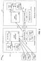
- FIG. 3is a detailed block diagram of a network management system 300 in accordance with an embodiment of the invention.
- the network management system 300includes a sending station 302 and a receiving station 304.
- the sending station 302includes a local network management (NM) console 306, a management database 308, a NM log file 310, and an event dispatcher 312.
- the event dispatcher 312receives event and traps from agent 314 over link 316, from agent 318 over link 320, and from agent 322 over link 324.
- the agents 314, 318 and 322are used to monitor network elements of a network (not shown).
- the local network management (NM) console 306, the management database 308, the NM log file 310, and the event dispatcher 312form a local NM system such as provided by a SunNet Manager console.
- the sending station 302further includes a sender process 326, an authorization list 328 and filter files 330.
- the receiving station 304includes a local NM console 332, a management database 334, and an event dispatcher 336.
- the local network management (NM) console 332, the management database 334, and the event dispatcher 312form a local NM system such as provided by a SunNet Manager console.
- the receiving station 304further includes a receiver process 338 and a registration list 340.
- the registration list 340is modified to contain information identifying the particular sending station from which network management information desired.
- the registration list 340preferable identifies a host machine (i.e., sending station), filter file, and database.
- the registration information contained in the registration list 340specifies the particular database involved when sending stations have multiple databases to choose from, the appropriate event forwarding criteria (i.e., filter file) to be used by the sender process, and the sending stations to which a receiving station is to register. It is assumed here that the receiving station 304 desires network management information from the sending station 302.
- the receiver process 338requests connection to the sender process 326 of the sending station 302 using a connection request 342.
- the sender process 326uses the authorization list 328 to determine whether the receiving station 304 (or the receiver process 338) is authorized to receive network management information from the sender process 326.
- the receiver process 338is able to successfully register with the sender process 326 and access a given local database, only if that receiving station 304 is authorized to register with the sender process 326 and access the specified database.
- the authorization list 328is used to determine whether the receiver process 338 is so authorized. Hence, by using the authorization list 328, unauthorized eavesdropping can be prevented.
- a separate child sender processbe spawned for each receiving station that registers with the sending station 302 and that a separate child receiver process be spawned for each sending station that the receiving station 304 desires to receive network management data from.
- the sender process 326registers with the event dispatcher 312 so as to receive all the network management information that the event dispatcher 312 receives due to local network management at the sending station.
- the network management informationincludes events and traps from the agents 314, 318 and 322 as well as database traps from the management database 308.
- the sender process 326thereafter filters the network management information (e.g., event and traps) received from the event dispatcher 312 using a particular one of the filter files 330 as identified by the receiver process 338 during connection.
- the filtering operationdiscourages unnecessary forwarding of network management information.
- the network management information remaining after the filteringis referred to as filtered data.
- the filtered datacan be grouped into two classes of data, namely, database traps and non-database traps and events.
- the database trapsare forwarded to the receiver process 338 using a message 344.
- the receiver process 338then supplies the database traps to the management database 334 via a link 346.
- the management database 334can then be modified in accordance with the database trap forwarded by the sender process 326.
- the local NM console 332can be updated in accordance with the updates to the management database 334 using link 348.
- the local NM console 332will update its view based on the changes to the management database 334.
- the non-database traps and eventsare forwarded by the sender process 326 to the event dispatcher 336 directly using a message 350.
- the event dispatcher 336can then update the local NM console 332 over link 352.
- the receiver process 338uses the database Application Programming Interface (API) of the local NM console 332 to update the local database 334 to reflect the topology information received from the sending station.
- APIApplication Programming Interface
- the updating of the database 334is preferably achieved as follows.
- the receiver process 338receives a database (topology) trap from the sender process 326
- the receiver process 338reads the local database 334 to determine if the element associated with the database trap already exists. If the element does not exist in the local database 334, then it is added to the local database 334. If an element already exists in the local database 334, the receiver process 338 determines whether the forwarded features of the element match those already attributed to the element.
- the local database 334can protect its elements (records) from being overwritten by configuring the sender process 326 such that it does not forward database traps for those elements not to be overwritten.
- view membership informationis passed (such as with a Background type database trap)
- elementsare added to the specified views if the views already exist in the local database 334. If the view is not yet present in the local database 334 at the receiving station 304, then the element can be added to a temporary holding area view.
- the systemcan also be configured so that the elements (components, views, etc.) that are added to the local database 334 can be left in the holding area view and even grouped in a different holding area view for each sending station.
- the local event dispatcher 336preferably receives event-related traps from the sender process 326 of the sending station 302. The event dispatcher 336 then forwards the information to the local NM console 332. The event dispatcher 336 on the receiving station does not receive the NM database traps forwarded by the sender process because such topology information is sent to the receiver process 338 on the receiving station 304.
- the event dispatcher 312receives events produced in response to event requests launched by the NM console 306.
- the event dispatcher 312forwards the events to the sender process 326.
- the sender processreformats all traps and NM events into NM traps before forwarding them to the event dispatcher 336 on the receiving station 304.
- the event dispatcher 304passes the traps to the local NM console 332.
- a NM eventis converted into a trap before being sent to a receiving station because the local NM (SunNet) console at the receiving station will ignore NM events that it cannot match to one of its own event requests.
- the reformattingfor example, adds an indicator to the event information so that the receiving station can easily identify that the event or trap was forwarded from a sending station.
- Each of the local NM consoles 306, 332 of the network management system 300preferably has a graphical user interface (GUI) that displays on a display screen.
- GUIgraphical user interface
- the GUIenables an end-user to configure operations of the network management system 300. For example, an end-user preferably modifies the registration list 340 using a GUI.
- FIGS. 4A and 4Bare flow diagrams illustrating receiver processing 400 in accordance with an embodiment of the invention.
- the receiver processing 400is carried out by a receiver process such as the receiver process 214 of FIG. 2 or the receiver process 338 of FIG. 3.
- the first operation of the receiver processing 400is to initialize 402 the receiver process. Then, a registration file is read 404. Next, the receiver processing 400 requests 406 connection of the receiving station 204, 304 to the sending station 202, 302. More particularly, the connection requested 406 is of the receiver process to the sender process. Next, a decision 408 is made based on whether a connection has been established. If no connection has been established, a decision 410 determines whether a time-out has occurred. If a time-out has not yet occurred, the processing returns to the decision block 408. Otherwise, if a time-out has occurred, the user is notified 412 of the failure to connect and the receiver processing 400 ends.
- a decision 414is made based on whether data (i.e., network management information) has been received from the sender process. If data has been received, the data received is processed 416 in the local network manager 212, 332. If, on the other hand, data is not received from the sender process, a decision 418 is made based on whether a time-out has occurred. If a time-out has not yet occurred, the processing returns to repeat the decision block 414 and subsequent blocks. If the time-out has occurred, the receiver processing 400 skips block 416.
- datai.e., network management information
- a decision 420is made based on whether user input has been received. If no user input has been received, the receiver processing 400 returns to repeat the decision block 414 and subsequent blocks. On the other hand, if user input has been received, a decision block 422 determines whether the user has requested disconnection. If the user has requested disconnection, the receiver processing 400 requests 424 disconnection from the sender process 206, 326. Subsequent to the block 424, the receiver processing 400 ends. On the other hand, when the decision block 422 determines that disconnection has not been requested by the user, the receiver processing 400 performs 426 other actions as requested by the user. Examples of other actions requested by the user include manual synchronization and configuration of new connection. Following block 426, the receiver processing 400 repeats the decision block 414 and subsequent blocks.
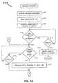
- FIG. 5is a flow diagram of sender processing 500 in accordance with an embodiment of the invention.
- the sender processing 500is carried out by a sender process such as the sender process 206 of FIG. 2 or the sender process 326 of FIG. 3.
- the sender processing 500is initiated in response to the first connection request from a receiving station.
- the sender processing 500first initializes 502 the sender process. During initialization, various internal data structures and data states are initialized.
- the sender processing 500reads 504 the authorization list 208, 328.
- the sender processing 500registers 506 the sender process with the network manager 205, 312 (event dispatcher).
- a decision block 508determines whether a connection request has been made by a receiver process. If a connection request has been received at the sender process, a decision block 510 determines whether the receiver process (or receiving station) is authorized to receive data from the sending station. The decision block 510 determines whether the receiver process is authorized using the authorization list 208, 328.
- connection of the receiver process to the sender processis established 512.
- the receiver processpreferably also passes the sender process a database name and the filter file name.
- the database nameselects the particular database from which to forward database traps when there are multiple databases at the sending station.
- the filter file namespecifies the filter file that contains the filter table with the desired filter criteria. Otherwise, if the receiver process is not authorized, the user is notified 514 that the receiver process is unauthorized.
- the connection requestwill fail if the receiver process passes the name of a non-existent filter file or a database that the receiver process is not authorized to access the selected database. Following blocks 512 or 514 in the case of a receiver connection request, the sender processing 500 returns to repeat the decision block 508 and subsequent blocks.
- the decision block 508causes the sender processing 500 to proceed to decision block 516.
- the decision block 516determines whether data has been received from the local network manager 205, 312 (event dispatcher). If no data has been received from the network manager 205, 312, the sender processing 500 returns to repeat the decision block 508 and subsequent blocks. Otherwise, when data has been received from the network manager 205, 312, the sender processing 500 applies 518 filtering.
- the filtering operationis discussed in more detail below with reference to FIG. 6. Generally speaking, the filtering operation filters the data (i.e., network management information) so that only the data requested by the receiver process (receiving station) remains after the filtering operation.
- a decision block 520determines whether there is data remaining after the filtering has been applied 518. If there is no data remaining, then there is no data to forward to the receiver process; hence, the sender processing 500 returns to repeat the decision block 508 and subsequent blocks.
- the filtered datais forwarded 522 to the appropriate receiver process.
- the appropriate receiver processis the receiver process that has requested the data be transmitted thereto. Then, following block 522, the sender processing 500 returns to repeat decision block 508 and subsequent blocks.
- the sender processunregisters from the network manager 205, 312 (event dispatcher) and exits thereby ending the sender processing 500.
- a receiving stationcan choose to register with multiple sending stations. Also, multiple receiver processes on various receiving stations can register with a sender process on a given sending station and the filter criteria can be configured separately for each receiving station. Preferably, for each pair sending and receiving stations, a dedicated pair of child processes (i.e., a child sender process and a child receiver process) are used to manage the processing.
- a dedicated pair of child processesi.e., a child sender process and a child receiver process
- FIG. 6is a flow diagram of filter processing 600 in accordance with an embodiment of the invention.
- the filter processing 600is the processing preferably carried out by block 518 in FIG. 5.
- the filter processing 600begins with a decision block 602 which determines whether the host name of the data received at the sender process (from the network manager 205 or the event dispatcher 312 thereof) matches the host name listed in a filter table residing in or identified by the filter files 210, 330. If not, a decision block 604 determines whether or not the component of the data received at the sender process matches the component listed in the filter table. Preferably, the filter table and/or filter file for a particular receiver process (receiving station) are selected by the receiver process when the connection request is accepted. If the decision block 604 determines that the component of the data received does not match the component in the filter table, the data received is dropped 608 and filter processing 600 ends.
- a decision block 606determines whether the priority level of the data received (data priority) is greater than or equal to a priority level identified in the filter table (filter priority level). Typically, the priority levels would be low, medium and high. If the data priority of the data received is less than the filter priority level, then the data is dropped 608 and the filter processing 600 ends. On the other hand, if the data priority exceeds or is equal to the filter priority level, the proper attributes are passed 610. The attributes to be passed are identified in the filter table. Thereafter, the priority level of the data received is optionally adjusted 612 in accordance with information identified in the filter table. It is preferable to adjust the priority of the data received to low priority because normally the shared network management information has a low priority regardless of the fact that the priority might have been high at its local network manager. Following block 612, the filter processing 600 ends.
- each filter table residing in or identified by the filter files 210, 330preferably includes the following six fields.
- the filter table(via the DB Template field) specifies the database template file to determine the topology information that should be forwarded for NM database traps that match the Name field of the filter table.
- Each filter in the filter tablecan specify a database template file used for elements that match the selection criteria of the filter.
- the database template filesare only accessed in response to NM database traps because non-database traps or events do not cause the sender process to forward topology information to the remote receiver process.
- the database template filesspecify the information (e.g., agents, attributes, color, connections, and membership) to be passed or forwarded for each type of trap (i.e., add, create, change, delete, load and background.)
- the network manager 202 or the local NM console 306generate six different types of NM database traps. These representative types of NM database traps are as follows:
- the sender process 326uses the filter file 330 specified for the receiving station 304 to determine which database template file to use in processing the database trap.
- the DB Template field in the filter tablecontains the database template file name.
- the database template fileallows you to specify additional topology information that should be forwarded. Because the filter table allows you to specify different DB Template files in each filter, an end-user can use the filter selection criteria to specify different types of topology information to forward for different devices (by hostname or element type.
- a representative DB Template filehas the format shown in Table 1 below.
- Database Template File FormatTrap Type Keywords (one or more can be specified) Add membership, color, agents, attributes, connections, drop Create membership, color, agents, attributes, connections, drop Change membership, color, agents, attributes, connections, drop Delete drop Load membership, color, agents, attributes, connections, drop Background drop
- the keywords in the above tabledetermine the forwarded content for each of these four trap types.
- the keywordshave the following interpretation:
- a GUIis used to configure a sender and receiver processes of the network management system according to the invention.
- the end-useris able to configure the information sharing provided by the invention with minimal effort.
- the GUIwould allow the user to easily define the following: (i) the list of remote receiving stations authorized to register with the local sender process and the databases that the receiving stations are authorized to access, (ii) filter files and database templates that determine the event and topology information forwarded by the sender process, and (iii) the list of remote management stations the receiver process will attempt to register within the database instance and the filter file that it will request at the sending station.
- all traps directed to the receiver processare sent to the receiver's transient RPC number.
- the RPC numberis provided to the sender process as part of the registration process.
- Another feature of the inventionconcerns the synchronization of the databases at the sending station and the receiving station.
- the sending stationis forwarding network management information to the receiving station in the form of database traps concerning topology of the network being monitored by the sending station, it is desirable that the portion of the database of the receiving station be synchronized with the database of the sending station. If the databases are not synchronized, then a network administrator at the receiving station would visualize a view based on stale data. Also, traps for devices not in the database of the receiving station will be ignored, thus leading to incomplete monitoring of the remote network.
- the synchronization of the databasescan be achieved whenever the network management system is started-up, or automatically as a user configures, or even manually whenever the site manager (network administrator) so requests.
- the synchronization provided by the inventionis automatic once a request for synchronization is made by the receiving station.
- the synchronization operationautomatically operates to synchronize the topology data contained in the database of the receiving station with the corresponding topology data contained in the database of the sending station.
- FIG. 7illustrates a flow diagram of synchronization processing 700 in accordance with an embodiment of the invention.
- the receiver process 214, 338sends a synchronization request to the sender process 206, 326.
- the sender process 206, 326in response to the synchronization request, the sender process 206, 326 generates 704 database traps at the sending station.
- the database trapsare filtered 706 at the sender process 206, 326.
- the filtering 706corresponds to the database trap filtering (block 610) performed in accordance with the filter processing 600 shown in FIG. 6.
- the filtered database trapsare forwarded 708 to the receiver process 214, 338.
- the receiver process 338causes the database at the receiving station 204, 304 to be updated 710 in accordance with the filtered database traps.
- the updating 710in effect synchronizes the database at the receiving station 204, 304 with the database at the sending station 202, 302 to the extent permitted (via filtering) by the end-user.
- FIGS. 8A and 8Bare flow diagrams of initialization processing 800 according to a more detailed embodiment of the invention.
- the initialization processing 800synchronizes databases of the sending station and the receiving station upon initiation of the network management system. Because the initialization processing 800 is done upon initialization, the initialization processing 800 additionally includes operations performed by the initialization operation 402 in FIG. 4A and the initialization operation 502 in FIG. 5.
- the first operation of the initialization processing 800is to invoke 802 a parent process at the sending station and the receiving station.
- a decision 804is made based on whether the initialization sequence is configured to request a connection at start-up. If not, the initialization processing 800 ends because in this case a connection is not requested upon initialization.
- the initialization processing 800performs other operations to carry out the connection as well as the synchronization operation. Namely, the initialization processing 800 invokes 806 a child receiver process at the receiving station 204, 304.
- the receiver process 214, 338spawns the child receiver process to interact with a particular sending station 202, 302.
- the child receiver processsends 808 a synchronization / registration request to the sender process 206, 326.
- the synchronization / registration requestincludes a connection request as discussed above together with a request for initial synchronization.
- the sender process 206, 326invokes 810 a child sender process at the sending station 202, 302.
- the child sender processis used to forward the filtered data through the child receiver process via the event dispatcher 312.
- the sender process and receiver processeffectively off loads processing tasks to the child processes such that they can manage incoming requests or connections and disconnections without being blocked by other processing operations.
- the sender process 206, 326invokes 812 a child synchronization process to generate database traps and to deliver the database traps to the sender process.
- the sender processinvokes 812 the child synchronization process which is a temporary process that reads through the entire database at the sending station 202, 302 and generates the database traps as it steps through the database.
- the child synchronization processthen delivers the database traps to the sender process 206, 326 and then exits.
- the sender process 206, 326forwards 814 the database traps to the child sender process.
- the database trapsare filtered 816. The filtering performs the same operations as noted by block 610 in FIG. 6.
- the filtered database trapsare forwarded 818 to the child receiver process of the receiving station 204, 304. Thereafter, the database at the receiving station is updated 820 in accordance with the filtered database traps.
- the updating 820is carried out as discussed above.
- a propertycan be added to each of the databases to provide the identification of the data being synchronized.
- the propertyhas a value which uniquely identifies each object in the database.
- Each componentwill have the property and the value of the property will preferably take the form of "Sender_hostname": filter_filename: database_name”.
- Synchronizationis always initiated by the receiver process. If the receiver process is currently synchronizing when another synchronization request is initiated (i.e., a manual synchronization request) toward the same connection, the current synchronization operation is preferably halted and a new synchronization process is started.
- the processing associated with halting the current synchronization operation and starting a new operationis as follows. First, the receiver process can tell the child receiver process to send a delete request to the sender process. The child receiver process then terminates itself. As a result of the delete request, the sender process terminates the child sender process. The receiver process then invokes a new child receiver process which deletes all the elements from the database at the receiving station having the properties for that connection.
- the new child receiver processthen sends a synchronization request to the sender process.
- the sender processthen invokes a new child sender process and a new child synchronization process.
- the new child synchronization processgenerates the database traps and delivers them to the new sender process which in turn forwards them to the child sender process.
- the child sender processthen filters the database traps and forwards the filtered database traps to the new child receiver process.
- the new child receiver processwill add the objects to the database at the receiving station with the appropriate value of the new property.
- the value of the property for an objectpreferably contains the sender's hostname with which the receiver synchronizes with first.
- the usercan over-ride this option by manually deleting the object and re-synchronizing with the second site.
- the receiver processoperates to receive all the database traps from the sending station unless filtered out. After receiving the database traps this receiver process updates the database and the receiving station. With synchronization, the topology data stored in the database at the receiving station can be synchronized to the corresponding topology data stored in the database at the sending station.
- the filteringallows synchronization to take place for only certain types of database traps.
- GUIgraphical user interface
- permission to delete an object from a database at the receiving stationcan be restricted to only those sites which are the source of the particular objects being deleted.
- the usercan select an option to synchronize at start-up which follows the processing described above with reference to FIGS. 8A and 8B. This type of synchronization initiation would occur on a normal start-up or after a crash of the system.
- the usercan also select whether the synchronization of the databases shall occur automatically, and if so, how often (e.g., on a daily or weekly basis).
- FIG. 9is a diagram of a representative network arrangement 900 according to the invention.
- the networkmay be the same network or a portion of the large overall network being managed by the network management system according to the invention.
- the networkmay take any suitable form.
- the network arrangement 900 shown in FIG. 9includes a first computer 902 which is coupled to a transmission line 904.
- the network arrangement 900further includes a server, router or the like 906 in addition to other computers 908, 910, and 912 such that data and instructions can be passed among the networked computers.
- the design, construction and implementation of networkswill be familiar to those of skill in the art.
- a network management system according to the inventionpreferably resides and executes on networked computers such as the computers 902, 908, 910 and 912 and operates to manage the large overall network in a distributed manner while providing the ability to share critical network management information.
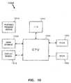
- FIG. 10is a block diagram of a representative computer 1000 suitable for use with the invention.
- the representative computer 1000is suitable for use as computers 902, 908, 910, and/or 912 of FIG. 9.
- the computer 1000includes a central processing unit (CPU) 1002 which is coupled bidirectionally with random access memory (RAM) 1004 and unidirectionally with read only memory (ROM) 1006.
- the RAM 1004is used as a "scratch pad" memory and includes programming instructions and data, including distributed objects and their associated code and state, for processes currently operating on the CPU 1002.
- the ROM 1006typically includes basic operating instructions, data and objects used by the computer to perform its functions.
- Mass storage device 1008such as a hard disk, CD ROM, magneto-optical (floptical) drive, tape drive or the like, is coupled bidirectionally with the CPU 1002.
- Mass storage device 1008generally includes additional programming instructions, data and objects that typically are not in active use by the CPU, although the address space may be accessed by the CPU 1002, e . g ., for virtual memory or the like.
- the computer 1002may optionally include an input/output source 1010 that typically includes input media such as a keyboard, pointer devices ( e . g ., a mouse or stylus) and/or network connections. Additional mass storage devices (not shown) may also be connected to the CPU 1002 through a network connection.
- the computer 1000further includes a display screen 1012 for viewing text and images generated or displayed by the computer system 1000.
- the CPU 1002together with an operating system (not shown) operate to execute computer code.
- the computer codemay reside on the RAM 1004, the ROM 1006, or a mass storage device 1008.
- the computer codecould also reside on a portable program medium 1014 and then be loaded or installed onto the computer 1000 when needed.
- Portable program mediums 1014include, for example, CD-ROMs, PC Card devices, RAM devices, floppy disk, magnetic tape.
Landscapes
- Engineering & Computer Science (AREA)
- Computer Networks & Wireless Communication (AREA)
- Signal Processing (AREA)
- Data Exchanges In Wide-Area Networks (AREA)
- Information Transfer Between Computers (AREA)
- Computer And Data Communications (AREA)
Description
| Database Template File Format | |
| Trap Type | Keywords (one or more can be specified) |
| Add | membership, color, agents, attributes, connections, drop |
| Create | membership, color, agents, attributes, connections, drop |
| Change | membership, color, agents, attributes, connections, drop |
| Delete | drop |
| Load | membership, color, agents, attributes, connections, drop |
| Background | drop |

- The first field should be "coop_forwarded_by". Each senderprocess adds one of these lines at the head of each report. Thevalue of this attribute should be the name of the local hostforwarding the report. This is used by the receiver process toprevent message loops, as well as by users, to determine whooriginated each message.
- The second field is the database trap type. The attribute namein this field is usually one of the following: changed, deleted,added, loaded, or created. The value is the name of theelement that this trap is being generated for.
- The next attribute is "type." The value of this attribute is thelocal NM (e.g., SunNet Manager) component type for theelement as represented in the local database.
- The next series of fields -- in this example, the fields fromIP_Address to SNMP_Timeout -- are determined by theschema definition for the component type. These fields can beany set of attributes as determined by the schema.
- The next three attributes specify the glyph color, in terms ofred, green, and blue values. The range of values should be aninteger from 0 to 255.
- Next there is a list of the views to which the element belongs.These views are listed with one "view=viewname" pair foreach view the element should be displayed in. Each"view=viewname" pair is to be followed by the positioninformation (X and Y coordinates) that defines the position ofthat element within that view. The valuesXlpos andYlposare only used for elements of type bus.ethemet.
- The "connected" attribute indicates what elements this elementhas been connected to. These connections are "simple"connections, not manageable components.
- Finally, a list of the element's agents is added to the end of thereport. Each entry in this list is of the form:"agent=agentname:proxy". In such an entry agentname:proxyrepresents the name of the agent that has been enabled,followed by information defining which host should be used asa proxy system. If an agent is not a proxy agent, only theagent name is provided, with no colon(":") or proxy name.
Claims (16)
- A network management system for sharing information between a plurality ofdistributed network managers (205, 212), said system comprising:wherein said information sharing means (206, 214, 216, 218; 326, 338, 340, 342,344) is configured to forward the information to said second network manager (212),if said authorization list (208; 328) authorizes said second network manager (212) toreceive the information.a first network manager (205) for managing a first network (108);a second network manager (212) for managing a second network (114);information sharing means (206, 214, 216, 218; 326, 338, 340, 342, 344) for sharinginformation between said first network manager (205) and said second networkmanager (212); andan authorization list (208; 328) containing information indicating whether saidsecond network manager (212) is authorized to receive information from said firstnetwork manager (205),
- A system as recited in claim 1, further comprising:wherein said sender process (206; 326) is configured to forward the event and trapinformation to said receiving machine (204; 304) if said authorization list (208; 328)authorizes said receiving machine (204; 304) to receive the event and trapinformation, anda sending machine (202; 302) including at least
said first network manager (205) for receiving event and trap information fromagents (110) associated with the first network (108);
said authorization list (208; 328) containing information indicating whetherreceiving machines (204, 304) are authorized to receive the event and trapinformation; and
a sender process (206; 326), operatively coupled to said first network manager(205), for receiving the event and trap information received by said first networkmanager (205);a receiving machine (204; 304) including at least
said second network manager (212) for managing a second network (114);
a receiver process (214; 338) for receiving the event and trap information; and
a registration list (216; 340) for identifying sender machines (202; 302) to whichsaid receiving machine (204; 304) is to connect to receive event and trapinformation; anda communication link (218; 342, 344) connecting said sending machine (202; 302)and said receiving machine (204; 304),
wherein said receiver process (214; 338) is configured to forward the event and trapinformation received from the sender process (206; 326) to said second networkmanager (212) for processing thereof. - A system as recited in claim 2, wherein said sender process (206; 326) is configuredto filter the event and trap information, and to then forward the filtered event and trapinformation to said receiving machine (204; 304) if said authorization list (208; 328)authorizes said receiving machine (204; 304) to receive the event and trapinformation.
- A system as recited in claim 3, wherein said sending machine (202; 302) furtherincludes a filter file (210; 330) containing filter tables, the filter tables beingconfigured to be utilized by said sender process (206; 326) to filter the event andtrap information.
- A system as recited in claim 2, wherein said first network manager (205) isconfigured to maintain a first database (308) and said second network manager(212) is configured to maintain a second database (334),
wherein said sender process (206; 326) is configured to receive a synchronizationrequest from said receiver process (214; 338) and in response thereto to generate adatabase trap for each record in the first database (308) and to then forward thedatabase traps to said receiver process (214; 338), and
wherein said receiver process (214; 338) is configured to receive the database trapsfrom said sender process (206; 326) and to then synchronizes the second database(334) to the first database (308) in accordance with the database traps. - A system as recited in claim 1 or 2, wherein the second network (114) is distinctfrom the first network (108).
- A system as recited in claim 1,
wherein the first network (108) includes a first set of agents (110) and the secondnetwork (114) includes a second set of agents (116), and wherein each of theagents (110, 116) is adapted to generate events or traps, and theinformation shaving means are arranged such thatthe information being shared between said first and second networkmanagers (205, 212) includes one or more of the events or traps generated by theagents (110, 116). - A system as recited in claim 1, wherein said information sharing means comprises:filter means (210; 330) for filtering the information before being transferred to saidsecond network manager (212); andmeans (218; 342, 344) for transferring the filtered information from said first networkmanager (205) to said second network manager (212).
- A system as recited in claim 1 or 8,
wherein said first network manager (205)comprises means for maintaining a first database (308) oftopology data for the first network (108) and the second network manager (212)maintains a second database (334) of topology data for the second network (114),and
wherein said system further comprises means for automatically synchronizingtopology data between said first and second databases (308, 334). - A network management method for sharing network management data between firstand second network managers (205, 212), the first network manager (205) locallymanaging a first network (108), and the second network manager (212) locallymanaging a second network (114), said method comprising the steps of:(a) connecting (406, 408) a receiver process (214; 338) associated with thesecond network (114) to a sender process (206; 326) associated with the firstnetwork (108);(b) receiving, at the sender process (206; 326), network management data for thefirst network (108);(c) forwarding (414) the network management data from the sender process (206;326) to the receiver process (214; 338), in case the receiver process (214;338) is authorized to receive information from the sender process (206; 326);and(d) processing (416) the network management data in the second networkmanager (212).
- A network management method as recited in claim 10, wherein the networkmanagement data includes event and trap data.
- A network management method as recited in claim 11, wherein the trap dataincludes one or both of database traps and non-database traps.
- A network management method as recited in claim 10, wherein said method furthercomprises: (e) filtering(518), prior to said forwarding (c), the network managementdata at the sender process (206; 326) to produce filtered data for the receiverprocess (214; 338).
- A network management method as recited in claim 10,
wherein the first network manager (205) maintains a first database (308) and thesecond network manager (212) maintains a second database (334), and
wherein said method further comprises: (e) automatically synchronizing the seconddatabase (334) to the first database (308). - A network management method as recited in claim 14, wherein said synchronizing(e) comprises the steps of:(e1) sending (702) a synchronization request from the receiver process (214; 338)to the sender process (206; 326);(e2) generating (704) database traps for the entire contents of the first database(308);(e3) forwarding (708) the database traps to the receiver process (214; 338); and(e4) updating (710) the second database (334) in accordance with the databasetraps.
- A network management method as recited in claim 15, wherein said synchronizing(e) further comprises the step of: (e5) filtering (706) the database traps prior to saidforwarding (e3) and said updating (e4).
Applications Claiming Priority (2)
| Application Number | Priority Date | Filing Date | Title |
|---|---|---|---|
| US08/550,087US5758083A (en) | 1995-10-30 | 1995-10-30 | Method and system for sharing information between network managers |
| US550087 | 1995-10-30 |
Publications (3)
| Publication Number | Publication Date |
|---|---|
| EP0772319A2 EP0772319A2 (en) | 1997-05-07 |
| EP0772319A3 EP0772319A3 (en) | 1999-03-24 |
| EP0772319B1true EP0772319B1 (en) | 2005-03-16 |
Family
ID=24195693
Family Applications (1)
| Application Number | Title | Priority Date | Filing Date |
|---|---|---|---|
| EP96116268AExpired - LifetimeEP0772319B1 (en) | 1995-10-30 | 1996-10-10 | Method and system for sharing information between network managers |
Country Status (4)
| Country | Link |
|---|---|
| US (1) | US5758083A (en) |
| EP (1) | EP0772319B1 (en) |
| JP (1) | JPH09190394A (en) |
| DE (1) | DE69634468D1 (en) |
Cited By (2)
| Publication number | Priority date | Publication date | Assignee | Title |
|---|---|---|---|---|
| DE102006003391A1 (en)* | 2006-01-24 | 2007-07-26 | Siemens Ag | Network management systems operating method for managing e.g. mobile radio communication system, involves storing information independent of changing of values and using information to identify units during communication |
| US11057309B2 (en) | 2017-02-27 | 2021-07-06 | Huawei Technologies Co., Ltd. | Management method, management unit, and system |
Families Citing this family (281)
| Publication number | Priority date | Publication date | Assignee | Title |
|---|---|---|---|---|
| CA2132363A1 (en)* | 1994-09-19 | 1996-03-20 | Norman Wong | Integrated management of multiple networks of different technologies through hierarchical pass-through routing and multi-network service management |
| US6502126B1 (en)* | 1995-04-28 | 2002-12-31 | Intel Corporation | Method and apparatus for running customized data and/or video conferencing applications employing prepackaged conference control objects utilizing a runtime synchronizer |
| US5848243A (en)* | 1995-11-13 | 1998-12-08 | Sun Microsystems, Inc. | Network topology management system through a database of managed network resources including logical topolgies |
| US5870542A (en)* | 1995-12-28 | 1999-02-09 | Sterling Commerce, Inc. | Security apparatus and method for a data processing system |
| US5826014A (en)* | 1996-02-06 | 1998-10-20 | Network Engineering Software | Firewall system for protecting network elements connected to a public network |
| DE69712552T2 (en)* | 1996-02-14 | 2003-01-09 | Hitachi Ulsi Systems Co., Ltd. | Method for monitoring a computer system with distribution of performance data to several monitoring processes |
| US6185611B1 (en)* | 1998-03-20 | 2001-02-06 | Sun Microsystem, Inc. | Dynamic lookup service in a distributed system |
| JPH09298544A (en)* | 1996-05-08 | 1997-11-18 | Fujitsu Ltd | Network operation management device |
| US5793951A (en)* | 1996-05-10 | 1998-08-11 | Apple Computer, Inc. | Security and report generation system for networked multimedia workstations |
| US5872931A (en)* | 1996-08-13 | 1999-02-16 | Veritas Software, Corp. | Management agent automatically executes corrective scripts in accordance with occurrences of specified events regardless of conditions of management interface and management engine |
| US5948055A (en)* | 1996-08-29 | 1999-09-07 | Hewlett-Packard Company | Distributed internet monitoring system and method |
| US6662205B1 (en)* | 1996-10-01 | 2003-12-09 | International Business Machines Corporation | Scaleable and extensible system management architecture with dataless endpoints |
| US5832529A (en) | 1996-10-11 | 1998-11-03 | Sun Microsystems, Inc. | Methods, apparatus, and product for distributed garbage collection |
| US5944782A (en)* | 1996-10-16 | 1999-08-31 | Veritas Software Corporation | Event management system for distributed computing environment |
| US6141664A (en) | 1996-11-13 | 2000-10-31 | Puma Technology, Inc. | Synchronization of databases with date range |
| US5943676A (en) | 1996-11-13 | 1999-08-24 | Puma Technology, Inc. | Synchronization of recurring records in incompatible databases |
| US6330568B1 (en) | 1996-11-13 | 2001-12-11 | Pumatech, Inc. | Synchronization of databases |
| US7302446B1 (en) | 1996-11-13 | 2007-11-27 | Intellisync Corporation | Synchronizing databases |
| US7013315B1 (en) | 1996-11-13 | 2006-03-14 | Intellisync Corporation | Synchronization of databases with record sanitizing and intelligent comparison |
| US6212529B1 (en) | 1996-11-13 | 2001-04-03 | Puma Technology, Inc. | Synchronization of databases using filters |
| US6405218B1 (en) | 1996-11-13 | 2002-06-11 | Pumatech, Inc. | Synchronizing databases |
| US6539426B1 (en)* | 1997-01-28 | 2003-03-25 | British Telecommunications Public Limited Company | Managing operation of servers in a distributed computing environment |
| JP3507270B2 (en)* | 1997-02-20 | 2004-03-15 | 株式会社日立製作所 | Network management system, network equipment, network management method, and network management tool |
| US6052722A (en)* | 1997-03-07 | 2000-04-18 | Mci Communications Corporation | System and method for managing network resources using distributed intelligence and state management |
| US8914410B2 (en) | 1999-02-16 | 2014-12-16 | Sonicwall, Inc. | Query interface to policy server |
| US7272625B1 (en) | 1997-03-10 | 2007-09-18 | Sonicwall, Inc. | Generalized policy server |
| US7580919B1 (en) | 1997-03-10 | 2009-08-25 | Sonicwall, Inc. | Query interface to policy server |
| US6408336B1 (en) | 1997-03-10 | 2002-06-18 | David S. Schneider | Distributed administration of access to information |
| US7912856B2 (en)* | 1998-06-29 | 2011-03-22 | Sonicwall, Inc. | Adaptive encryption |
| US6105027A (en)* | 1997-03-10 | 2000-08-15 | Internet Dynamics, Inc. | Techniques for eliminating redundant access checking by access filters |
| US7821926B2 (en) | 1997-03-10 | 2010-10-26 | Sonicwall, Inc. | Generalized policy server |
| US5978845A (en)* | 1997-03-25 | 1999-11-02 | Sun Microsystems, Inc. | Network management relay mechanism |
| US6240186B1 (en)* | 1997-03-31 | 2001-05-29 | Sun Microsystems, Inc. | Simultaneous bi-directional translation and sending of EDI service order data |
| US6240441B1 (en) | 1997-03-31 | 2001-05-29 | Sun Microsystems, Inc. | Secure event-driven EDI transaction processing using the internet |
| US6724896B1 (en) | 1997-03-31 | 2004-04-20 | Sun Microsystems, Inc. | Event-driven servers for data extraction and merge for EDI transaction processing using the internet |
| US5964832A (en)* | 1997-04-18 | 1999-10-12 | Intel Corporation | Using networked remote computers to execute computer processing tasks at a predetermined time |
| JP4187178B2 (en)* | 1997-05-09 | 2008-11-26 | アルカテル・ユー・エス・エイ・ソーシング、エル・ピー | Rapid database synchronization communication system |
| JP3490256B2 (en)* | 1997-06-12 | 2004-01-26 | 三菱電機株式会社 | Agent method |
| AU740146B2 (en)* | 1997-06-16 | 2001-11-01 | Telefonaktiebolaget Lm Ericsson (Publ) | A telecommunications performance management system |
| US6266694B1 (en)* | 1997-06-19 | 2001-07-24 | Nortel Networks Limited | Architecture for network manager |
| US6226679B1 (en)* | 1997-06-30 | 2001-05-01 | Sun Microsystems, Inc. | Common management information protocol (CMIP) agent registration methods systems and computer program products |
| GB2328352A (en)* | 1997-08-12 | 1999-02-17 | Lucent Technologies Uk Limited | Redundant communication network |
| US6308206B1 (en)* | 1997-09-17 | 2001-10-23 | Hewlett-Packard Company | Internet enabled computer system management |
| US6279016B1 (en)* | 1997-09-21 | 2001-08-21 | Microsoft Corporation | Standardized filtering control techniques |
| GB2329790A (en)* | 1997-09-25 | 1999-03-31 | Dsc Telecom Lp | Maintaining information concerning subscriber terminals within a call routing system of a telecommunications system |
| US6216169B1 (en)* | 1997-10-06 | 2001-04-10 | Concord Communications Incorporated | Generating reports using distributed workstations |
| US6446075B1 (en)* | 1998-02-25 | 2002-09-03 | International Business Machines Corporation | System and method for automatically synchronizing different classes of databases utilizing a repository database |
| EP1057107A1 (en)* | 1998-02-26 | 2000-12-06 | Sun Microsystems, Inc. | Dynamic lookup service in a distributed system |
| US6233585B1 (en)* | 1998-03-12 | 2001-05-15 | Crossworlds Software, Inc. | Isolation levels and compensating transactions in an information system |
| US6925477B1 (en) | 1998-03-31 | 2005-08-02 | Intellisync Corporation | Transferring records between two databases |
| US6259448B1 (en)* | 1998-06-03 | 2001-07-10 | International Business Machines Corporation | Resource model configuration and deployment in a distributed computer network |
| US6377990B1 (en) | 1998-06-15 | 2002-04-23 | Lodgenet Entertainment Corporation | System for providing internet access from locations different from those for which the user's software was configured |
| US6144989A (en)* | 1998-06-15 | 2000-11-07 | Dejima, Inc. | Adaptive agent-oriented software architecture |
| US6138148A (en)* | 1998-06-18 | 2000-10-24 | Sun Microsystems, Inc. | Client intermediation of server applications |
| US6144987A (en)* | 1998-06-25 | 2000-11-07 | Cisco Technology, Inc. | System for characterizing information from an information producer |
| US6925483B1 (en)* | 1998-06-25 | 2005-08-02 | Cisco Technology, Inc. | System for characterizing information from an information producer |
| JP4035799B2 (en)* | 1998-09-01 | 2008-01-23 | 富士通株式会社 | Topology view control system in network management |
| US6141680A (en)* | 1998-09-01 | 2000-10-31 | Nortel Networks Limited | Method and apparatus for providing and facilitating interaction with distributed manager information of a network |
| US6230198B1 (en)* | 1998-09-10 | 2001-05-08 | International Business Machines Corporation | Server-to-server event logging |
| US6286047B1 (en)* | 1998-09-10 | 2001-09-04 | Hewlett-Packard Company | Method and system for automatic discovery of network services |
| US6185612B1 (en)* | 1998-10-29 | 2001-02-06 | Novell, Inc. | Secure distribution and use of weighted network topology information |
| US6425002B1 (en)* | 1998-11-23 | 2002-07-23 | Motorola, Inc. | Apparatus and method for handling dispatching messages for various applications of a communication device |
| US7007003B1 (en) | 1998-12-04 | 2006-02-28 | Intellisync Corporation | Notification protocol for establishing synchronization mode for use in synchronizing databases |
| US8713641B1 (en) | 1998-12-08 | 2014-04-29 | Nomadix, Inc. | Systems and methods for authorizing, authenticating and accounting users having transparent computer access to a network using a gateway device |
| US8266266B2 (en) | 1998-12-08 | 2012-09-11 | Nomadix, Inc. | Systems and methods for providing dynamic network authorization, authentication and accounting |
| US7194554B1 (en) | 1998-12-08 | 2007-03-20 | Nomadix, Inc. | Systems and methods for providing dynamic network authorization authentication and accounting |
| US6446136B1 (en)* | 1998-12-31 | 2002-09-03 | Computer Associates Think, Inc. | System and method for dynamic correlation of events |
| US6718137B1 (en)* | 1999-01-05 | 2004-04-06 | Ciena Corporation | Method and apparatus for configuration by a first network element based on operating parameters of a second network element |
| US6675196B1 (en) | 1999-01-08 | 2004-01-06 | Amazon.Com, Inc. | Universal protocol for enabling a device to discover and utilize the services of another device |
| AUPQ030299A0 (en)* | 1999-05-12 | 1999-06-03 | Sharinga Networks Inc. | A message processing system |
| US6944183B1 (en) | 1999-06-10 | 2005-09-13 | Alcatel | Object model for network policy management |
| US7032022B1 (en) | 1999-06-10 | 2006-04-18 | Alcatel | Statistics aggregation for policy-based network |
| US6847609B1 (en)* | 1999-06-29 | 2005-01-25 | Adc Telecommunications, Inc. | Shared management of a network entity |
| US6959006B1 (en) | 1999-06-29 | 2005-10-25 | Adc Telecommunications, Inc. | Service delivery unit for an enterprise network |
| US6539425B1 (en) | 1999-07-07 | 2003-03-25 | Avaya Technology Corp. | Policy-enabled communications networks |
| US6671722B1 (en)* | 1999-07-08 | 2003-12-30 | Intel Corporation | Stack-less, CPU-less creation of valid SNMP-trap packets |
| US6941374B1 (en)* | 1999-08-05 | 2005-09-06 | Amazon.Com, Inc. | Hidden agent transfer protocol |
| US6832341B1 (en)* | 1999-09-23 | 2004-12-14 | International Business Machines Corporation | Fault event management using fault monitoring points |
| US7346008B1 (en) | 1999-10-15 | 2008-03-18 | Alcatel Canada Inc. | Method and apparatus for data driven network management |
| US6657972B1 (en)* | 1999-10-15 | 2003-12-02 | Alcatel Canada Inc. | Method and apparatus for generic frame relay services support in a communication network |
| WO2001031885A2 (en) | 1999-10-22 | 2001-05-03 | Nomadix, Inc. | Gateway device having an xml interface and associated method |
| US7213068B1 (en)* | 1999-11-12 | 2007-05-01 | Lucent Technologies Inc. | Policy management system |
| US7774220B2 (en)* | 1999-11-29 | 2010-08-10 | The Strategic Coach Inc. | Project management system for aiding users in attaining goals |
| US7331058B1 (en)* | 1999-12-16 | 2008-02-12 | International Business Machines Corporation | Distributed data structures for authorization and access control for computing resources |
| SE0000630D0 (en)* | 2000-02-25 | 2000-02-25 | Ericsson Telefon Ab L M | A method of providing synchronization in a UDP transport based management system |
| US8645137B2 (en) | 2000-03-16 | 2014-02-04 | Apple Inc. | Fast, language-independent method for user authentication by voice |
| US7337209B1 (en) | 2000-04-28 | 2008-02-26 | Sheer Networks, Inc. | Large-scale network management using distributed autonomous agents |
| US6941362B2 (en)* | 2000-04-28 | 2005-09-06 | Sheer Networks Inc. | Root cause analysis in a distributed network management architecture |
| EP1301864A4 (en)* | 2000-04-28 | 2005-09-07 | Sheer Networks Inc | NETWORK MANAGEMENT PROCESS AND SYSTEM |
| IL144709A (en) | 2000-08-03 | 2010-11-30 | Cisco Tech Inc | Path discovery in a distributed network management architecture |
| US7197555B1 (en) | 2000-09-13 | 2007-03-27 | Canon Kabushiki Kaisha | Directory server tracking tool |
| CA2345292A1 (en)* | 2000-10-03 | 2002-04-03 | Linmor Technologies Inc. | High performance distributed discovery system |
| US8122114B1 (en)* | 2000-10-06 | 2012-02-21 | Hewlett-Packard Development Company, L.P. | Modular, dynamically extensible, and integrated storage area network management system |
| US7113995B1 (en) | 2000-10-19 | 2006-09-26 | International Business Machines Corporation | Method and apparatus for reporting unauthorized attempts to access nodes in a network computing system |
| US6941350B1 (en) | 2000-10-19 | 2005-09-06 | International Business Machines Corporation | Method and apparatus for reliably choosing a master network manager during initialization of a network computing system |
| US6990528B1 (en) | 2000-10-19 | 2006-01-24 | International Business Machines Corporation | System area network of end-to-end context via reliable datagram domains |
| US7099955B1 (en) | 2000-10-19 | 2006-08-29 | International Business Machines Corporation | End node partitioning using LMC for a system area network |
| US7636772B1 (en) | 2000-10-19 | 2009-12-22 | International Business Machines Corporation | Method and apparatus for dynamic retention of system area network management information in non-volatile store |
| US6981025B1 (en)* | 2000-10-19 | 2005-12-27 | International Business Machines Corporation | Method and apparatus for ensuring scalable mastership during initialization of a system area network |
| US6978300B1 (en) | 2000-10-19 | 2005-12-20 | International Business Machines Corporation | Method and apparatus to perform fabric management |
| US7003559B1 (en) | 2000-10-23 | 2006-02-21 | Hewlett-Packard Development Company, L.P. | System and method for determining probable network paths between nodes in a network topology |
| JP3819231B2 (en)* | 2000-11-14 | 2006-09-06 | 株式会社日立コミュニケーションテクノロジー | Network management method and network management system |
| US20020073257A1 (en)* | 2000-12-07 | 2002-06-13 | Ibm Corporation | Transferring foreign protocols across a system area network |
| US7155436B2 (en)* | 2001-01-12 | 2006-12-26 | Vendaria, Inc | Method and system for generating and providing rich media presentations optimized for a device over a network |
| JP4044298B2 (en)* | 2001-04-10 | 2008-02-06 | 富士通株式会社 | Database synchronization method between monitoring devices |
| US7359920B1 (en) | 2001-04-18 | 2008-04-15 | Intellisync Corporation | Communication protocol for synchronization of personal information management databases |
| JP4953518B2 (en)* | 2001-05-14 | 2012-06-13 | ケープレックス・インク | Information sharing method and apparatus using object-oriented technology |
| US20020184334A1 (en)* | 2001-06-04 | 2002-12-05 | Cherry Darrel D. | System and method for providing intelligence to network devices |
| US6865637B1 (en)* | 2001-06-26 | 2005-03-08 | Alcatel | Memory card and system for updating distributed memory |
| US7904454B2 (en)* | 2001-07-16 | 2011-03-08 | International Business Machines Corporation | Database access security |
| US20030208572A1 (en)* | 2001-08-31 | 2003-11-06 | Shah Rajesh R. | Mechanism for reporting topology changes to clients in a cluster |
| US7756969B1 (en) | 2001-09-07 | 2010-07-13 | Oracle America, Inc. | Dynamic provisioning of identification services in a distributed system |
| US20030149762A1 (en)* | 2001-10-05 | 2003-08-07 | Knight Gregory John | Storage area network methods and apparatus with history maintenance and removal |
| US20030084200A1 (en)* | 2001-10-31 | 2003-05-01 | Vtel Corporation | System and method for generating programmable traps for a communications network |
| US6941358B1 (en)* | 2001-12-21 | 2005-09-06 | Networks Associates Technology, Inc. | Enterprise interface for network analysis reporting |
| US6892227B1 (en)* | 2001-12-21 | 2005-05-10 | Networks Associates Technology, Inc. | Enterprise network analyzer host controller/zone controller interface system and method |
| US7154857B1 (en)* | 2001-12-21 | 2006-12-26 | Mcafee, Inc. | Enterprise network analyzer zone controller system and method |
| US20030126307A1 (en)* | 2001-12-27 | 2003-07-03 | Siemens Aktiengesellschaft | Method and system for event management |
| EP1349315A1 (en)* | 2002-03-27 | 2003-10-01 | BRITISH TELECOMMUNICATIONS public limited company | Policy based system management |
| GB0207454D0 (en) | 2002-03-28 | 2002-05-08 | British Telecomm | Method of data transfer in mobile and fixed telecommunications systems |
| ATE363811T1 (en) | 2002-04-03 | 2007-06-15 | Evolium Sas | SPECIFIC DATA REGISTRATION SERVER IN AN OPERATING AND MANAGEMENT CENTER FOR A TELECOMMUNICATIONS SYSTEM |
| US7398326B2 (en)* | 2002-04-25 | 2008-07-08 | International Business Machines Corporation | Methods for management of mixed protocol storage area networks |
| DE10219389A1 (en)* | 2002-04-30 | 2003-11-20 | Siemens Ag | Method for using functions and hardware resources of a communication device by several operators |
| US20030229686A1 (en)* | 2002-06-07 | 2003-12-11 | Kris Kortright | System and method for synchronizing the configuration of distributed network management applications |
| US20040006619A1 (en)* | 2002-07-02 | 2004-01-08 | Fujitsu Network Communications, Inc. | Structure for event reporting in SNMP systems |
| US7103612B2 (en)* | 2002-08-01 | 2006-09-05 | Oracle International Corporation | Instantiation of objects for information-sharing relationships |
| US6889231B1 (en)* | 2002-08-01 | 2005-05-03 | Oracle International Corporation | Asynchronous information sharing system |
| US8005802B2 (en) | 2002-08-01 | 2011-08-23 | Oracle International Corporation | Partial evaluation of rule sets |
| US7031974B1 (en) | 2002-08-01 | 2006-04-18 | Oracle International Corporation | Replicating DDL changes using streams |
| US7523184B2 (en)* | 2002-12-31 | 2009-04-21 | Time Warner Cable, Inc. | System and method for synchronizing the configuration of distributed network management applications |
| EP1437859A1 (en)* | 2003-01-10 | 2004-07-14 | Siemens Aktiengesellschaft | Method of handling alarms by a management network with different layers in a communications system |
| DE10300709A1 (en)* | 2003-01-10 | 2004-08-05 | Siemens Ag | Handling alerts with multi-level management system in communications system involves aligning alert notices between element and network manager to synchronize notice information available to operators |
| US20050015455A1 (en)* | 2003-07-18 | 2005-01-20 | Liu Gary G. | SPAM processing system and methods including shared information among plural SPAM filters |
| US7552123B2 (en)* | 2003-08-13 | 2009-06-23 | At&T Intellectual Property I, L.P. | Methods, systems and computer program products for synchronizing records in billing and service databases |
| PL1661420T3 (en)* | 2003-09-04 | 2015-02-27 | Deutsche Telekom Ag | Push-to-talk interworking |
| US20050091316A1 (en)* | 2003-10-03 | 2005-04-28 | Oscar Ponce | System and method for creating and selectively sharing data elements in a peer-to-peer network |
| US7590072B2 (en)* | 2004-03-12 | 2009-09-15 | Alcatel Lucent | Interworking network maps of network management and element management systems |
| JP4315850B2 (en)* | 2004-03-30 | 2009-08-19 | 富士通株式会社 | Multicast data communication system, data communication apparatus, multicast data communication method and program |
| JP4418302B2 (en)* | 2004-05-31 | 2010-02-17 | 独立行政法人科学技術振興機構 | Relay device, packet filtering method, and packet filtering program |
| DE102004036259B3 (en)* | 2004-07-26 | 2005-12-08 | Siemens Ag | Network management with peer-to-peer protocol |
| US7925727B2 (en)* | 2004-07-29 | 2011-04-12 | Nortel Networks Limited | Method and apparatus for efficient communication of management data in a telecommunications network |
| DE602004011928T2 (en)* | 2004-08-02 | 2009-02-12 | Alcatel Lucent | Method for controlling a shared resource by different managers |
| US8316438B1 (en) | 2004-08-10 | 2012-11-20 | Pure Networks Llc | Network management providing network health information and lockdown security |
| US20060072626A1 (en)* | 2004-09-29 | 2006-04-06 | Lucent Technologies Inc. | Data synchronization in a telecommunication management network |
| US8478849B2 (en)* | 2004-12-07 | 2013-07-02 | Pure Networks LLC. | Network administration tool |
| WO2006063118A2 (en)* | 2004-12-07 | 2006-06-15 | Pure Networks, Inc. | Network management |
| US20060136519A1 (en)* | 2004-12-17 | 2006-06-22 | Anurag Batta | System and method for user database synchronization |
| US20080201454A1 (en)* | 2005-06-06 | 2008-08-21 | Chippc Israel Ltd. | Multi-Level Thin-Clients Management System and Method |
| US7970788B2 (en)* | 2005-08-02 | 2011-06-28 | International Business Machines Corporation | Selective local database access restriction |
| US8677377B2 (en) | 2005-09-08 | 2014-03-18 | Apple Inc. | Method and apparatus for building an intelligent automated assistant |
| US7680793B2 (en)* | 2005-10-07 | 2010-03-16 | Oracle International Corporation | Commit-time ordered message queue supporting arbitrary read and dequeue patterns from multiple subscribers |
| US7933923B2 (en) | 2005-11-04 | 2011-04-26 | International Business Machines Corporation | Tracking and reconciling database commands |
| US20070198993A1 (en)* | 2006-02-06 | 2007-08-23 | Zhongyao Zhang | Communication system event handling systems and techniques |
| US7801856B2 (en)* | 2006-08-09 | 2010-09-21 | Oracle International Corporation | Using XML for flexible replication of complex types |
| US9318108B2 (en) | 2010-01-18 | 2016-04-19 | Apple Inc. | Intelligent automated assistant |
| US7702660B2 (en) | 2006-12-12 | 2010-04-20 | Oracle International Corporation | I/O free recovery set determination |
| US8141100B2 (en) | 2006-12-20 | 2012-03-20 | International Business Machines Corporation | Identifying attribute propagation for multi-tier processing |
| US8495367B2 (en) | 2007-02-22 | 2013-07-23 | International Business Machines Corporation | Nondestructive interception of secure data in transit |
| US8977255B2 (en) | 2007-04-03 | 2015-03-10 | Apple Inc. | Method and system for operating a multi-function portable electronic device using voice-activation |
| US7778201B2 (en)* | 2007-06-29 | 2010-08-17 | World Wide Packets, Inc. | Determining a logical neighbor of a network element |
| US8805982B1 (en) | 2007-06-29 | 2014-08-12 | Ciena Corporation | Progressively determining a network topology and using neighbor information to determine network topology |
| US7773541B2 (en)* | 2007-06-29 | 2010-08-10 | World Wide Packets, Inc. | Obtaining identification information for a neighboring network element |
| US7835297B2 (en)* | 2007-06-29 | 2010-11-16 | World Wide Packets, Inc. | Determining the state of a tunnel with respect to a control protocol |
| US8700743B2 (en)* | 2007-07-13 | 2014-04-15 | Pure Networks Llc | Network configuration device |
| US9026639B2 (en)* | 2007-07-13 | 2015-05-05 | Pure Networks Llc | Home network optimizing system |
| US9491077B2 (en)* | 2007-07-13 | 2016-11-08 | Cisco Technology, Inc. | Network metric reporting system |
| US7801852B2 (en) | 2007-07-31 | 2010-09-21 | Oracle International Corporation | Checkpoint-free in log mining for distributed information sharing |
| US8046771B2 (en)* | 2007-09-12 | 2011-10-25 | International Business Machines Corporation | Generating and using constraints associated with software related products |
| ITTO20070938A1 (en)* | 2007-12-24 | 2009-06-25 | Selex Communications Spa | MANAGEMENT AND SUPERVISION SYSTEM OF EQUIPMENT CONNECTED IN A NETWORK ACCORDING TO THE SNMP PROTOCOL, BASED ON SWITCHING BETWEEN SNMP MANAGERS |
| US9330720B2 (en) | 2008-01-03 | 2016-05-03 | Apple Inc. | Methods and apparatus for altering audio output signals |
| US8996376B2 (en) | 2008-04-05 | 2015-03-31 | Apple Inc. | Intelligent text-to-speech conversion |
| US8261326B2 (en) | 2008-04-25 | 2012-09-04 | International Business Machines Corporation | Network intrusion blocking security overlay |
| US10496753B2 (en) | 2010-01-18 | 2019-12-03 | Apple Inc. | Automatically adapting user interfaces for hands-free interaction |
| US8675517B2 (en)* | 2008-05-20 | 2014-03-18 | Solarwinds Worldwide Llc | Filtering of map topology based on network discovery characteristics |
| US20100030549A1 (en) | 2008-07-31 | 2010-02-04 | Lee Michael M | Mobile device having human language translation capability with positional feedback |
| WO2010105260A1 (en)* | 2009-03-13 | 2010-09-16 | Assa Abloy Ab | Transfer device for sensitive material such as a cryptographic key |
| EP2228746A1 (en)* | 2009-03-13 | 2010-09-15 | Assa Abloy Ab | Realization of access control conditions as boolean expressions in credential authentications |
| US8332498B2 (en)* | 2009-03-13 | 2012-12-11 | Assa Abloy Ab | Synchronized relay messaging and coordinated network processing using SNMP |
| US9032058B2 (en) | 2009-03-13 | 2015-05-12 | Assa Abloy Ab | Use of SNMP for management of small footprint devices |
| WO2010105259A1 (en)* | 2009-03-13 | 2010-09-16 | Assa Abloy Ab | Secure card access module for integrated circuit card applications |
| US20100235900A1 (en)* | 2009-03-13 | 2010-09-16 | Assa Abloy Ab | Efficient two-factor authentication |
| US9858925B2 (en) | 2009-06-05 | 2018-01-02 | Apple Inc. | Using context information to facilitate processing of commands in a virtual assistant |
| US10241752B2 (en) | 2011-09-30 | 2019-03-26 | Apple Inc. | Interface for a virtual digital assistant |
| US20120309363A1 (en) | 2011-06-03 | 2012-12-06 | Apple Inc. | Triggering notifications associated with tasks items that represent tasks to perform |
| US10241644B2 (en) | 2011-06-03 | 2019-03-26 | Apple Inc. | Actionable reminder entries |
| US9431006B2 (en) | 2009-07-02 | 2016-08-30 | Apple Inc. | Methods and apparatuses for automatic speech recognition |
| US11138528B2 (en) | 2009-08-03 | 2021-10-05 | The Strategic Coach | Managing professional development |
| US11354614B2 (en) | 2009-09-16 | 2022-06-07 | The Strategic Coach | Systems and methods for providing information relating to professional growth |
| EP2523402A4 (en)* | 2010-01-05 | 2017-10-18 | Nec Corporation | Communication system, control apparatus, processing rule setting method, packet transmitting method and program |
| US10679605B2 (en) | 2010-01-18 | 2020-06-09 | Apple Inc. | Hands-free list-reading by intelligent automated assistant |
| US10553209B2 (en) | 2010-01-18 | 2020-02-04 | Apple Inc. | Systems and methods for hands-free notification summaries |
| US10276170B2 (en) | 2010-01-18 | 2019-04-30 | Apple Inc. | Intelligent automated assistant |
| US10705794B2 (en) | 2010-01-18 | 2020-07-07 | Apple Inc. | Automatically adapting user interfaces for hands-free interaction |
| DE112011100329T5 (en) | 2010-01-25 | 2012-10-31 | Andrew Peter Nelson Jerram | Apparatus, methods and systems for a digital conversation management platform |
| US8682667B2 (en) | 2010-02-25 | 2014-03-25 | Apple Inc. | User profiling for selecting user specific voice input processing information |
| US8724515B2 (en) | 2010-03-26 | 2014-05-13 | Cisco Technology, Inc. | Configuring a secure network |
| US8649297B2 (en)* | 2010-03-26 | 2014-02-11 | Cisco Technology, Inc. | System and method for simplifying secure network setup |
| CN102238613B (en)* | 2010-05-07 | 2014-03-12 | 中兴通讯股份有限公司 | Cooperation method and device between network manager and base station in LTE (long term evolution) system |
| GB2481423C (en) | 2010-06-23 | 2015-09-02 | Giraffic Technologies Ltd | Proactive seeding of data in a peer to peer network |
| CN101917226B (en)* | 2010-08-23 | 2016-03-02 | 中兴通讯股份有限公司 | A kind of method and optical line terminal carrying out fiber fault diagnosis in EPON |
| US9098279B2 (en) | 2010-09-14 | 2015-08-04 | Google Inc. | Methods and systems for data interchange between a network-connected thermostat and cloud-based management server |
| US9046898B2 (en) | 2011-02-24 | 2015-06-02 | Google Inc. | Power-preserving communications architecture with long-polling persistent cloud channel for wireless network-connected thermostat |
| US9262612B2 (en) | 2011-03-21 | 2016-02-16 | Apple Inc. | Device access using voice authentication |
| US10057736B2 (en) | 2011-06-03 | 2018-08-21 | Apple Inc. | Active transport based notifications |
| US8713649B2 (en) | 2011-06-03 | 2014-04-29 | Oracle International Corporation | System and method for providing restrictions on the location of peer subnet manager (SM) instances in an infiniband (IB) network |
| US8739273B2 (en) | 2011-07-11 | 2014-05-27 | Oracle International Corporation | System and method for supporting subnet management packet (SMP) firewall restrictions in a middleware machine environment |
| US8874742B2 (en) | 2011-07-11 | 2014-10-28 | Oracle International Corporation | System and method for supporting virtual machine migration in a middleware machine environment |
| US8994660B2 (en) | 2011-08-29 | 2015-03-31 | Apple Inc. | Text correction processing |
| US9483461B2 (en) | 2012-03-06 | 2016-11-01 | Apple Inc. | Handling speech synthesis of content for multiple languages |
| WO2013170205A1 (en) | 2012-05-10 | 2013-11-14 | Oracle International Corporation | System and method for supporting state synchronization in a network environment |
| US9280610B2 (en) | 2012-05-14 | 2016-03-08 | Apple Inc. | Crowd sourcing information to fulfill user requests |
| US9721563B2 (en) | 2012-06-08 | 2017-08-01 | Apple Inc. | Name recognition system |
| US9495129B2 (en) | 2012-06-29 | 2016-11-15 | Apple Inc. | Device, method, and user interface for voice-activated navigation and browsing of a document |
| US9547647B2 (en) | 2012-09-19 | 2017-01-17 | Apple Inc. | Voice-based media searching |
| US10225135B2 (en)* | 2013-01-30 | 2019-03-05 | Lenovo Enterprise Solutions (Singapore) Pte. Ltd. | Provision of management information and requests among management servers within a computing network |
| US9208032B1 (en)* | 2013-05-15 | 2015-12-08 | Amazon Technologies, Inc. | Managing contingency capacity of pooled resources in multiple availability zones |
| US9582608B2 (en) | 2013-06-07 | 2017-02-28 | Apple Inc. | Unified ranking with entropy-weighted information for phrase-based semantic auto-completion |
| WO2014197334A2 (en) | 2013-06-07 | 2014-12-11 | Apple Inc. | System and method for user-specified pronunciation of words for speech synthesis and recognition |
| WO2014197336A1 (en) | 2013-06-07 | 2014-12-11 | Apple Inc. | System and method for detecting errors in interactions with a voice-based digital assistant |
| WO2014197335A1 (en) | 2013-06-08 | 2014-12-11 | Apple Inc. | Interpreting and acting upon commands that involve sharing information with remote devices |
| DE112014002747T5 (en) | 2013-06-09 | 2016-03-03 | Apple Inc. | Apparatus, method and graphical user interface for enabling conversation persistence over two or more instances of a digital assistant |
| US10176167B2 (en) | 2013-06-09 | 2019-01-08 | Apple Inc. | System and method for inferring user intent from speech inputs |
| US9430463B2 (en) | 2014-05-30 | 2016-08-30 | Apple Inc. | Exemplar-based natural language processing |
| US9785630B2 (en) | 2014-05-30 | 2017-10-10 | Apple Inc. | Text prediction using combined word N-gram and unigram language models |
| US10078631B2 (en) | 2014-05-30 | 2018-09-18 | Apple Inc. | Entropy-guided text prediction using combined word and character n-gram language models |
| US9842101B2 (en) | 2014-05-30 | 2017-12-12 | Apple Inc. | Predictive conversion of language input |
| US9760559B2 (en) | 2014-05-30 | 2017-09-12 | Apple Inc. | Predictive text input |
| CN110797019B (en) | 2014-05-30 | 2023-08-29 | 苹果公司 | Multi-command single speech input method |
| US9715875B2 (en) | 2014-05-30 | 2017-07-25 | Apple Inc. | Reducing the need for manual start/end-pointing and trigger phrases |
| US10659851B2 (en) | 2014-06-30 | 2020-05-19 | Apple Inc. | Real-time digital assistant knowledge updates |
| US9338493B2 (en) | 2014-06-30 | 2016-05-10 | Apple Inc. | Intelligent automated assistant for TV user interactions |
| US10446141B2 (en) | 2014-08-28 | 2019-10-15 | Apple Inc. | Automatic speech recognition based on user feedback |
| US9818400B2 (en) | 2014-09-11 | 2017-11-14 | Apple Inc. | Method and apparatus for discovering trending terms in speech requests |
| US10789041B2 (en) | 2014-09-12 | 2020-09-29 | Apple Inc. | Dynamic thresholds for always listening speech trigger |
| US10127911B2 (en) | 2014-09-30 | 2018-11-13 | Apple Inc. | Speaker identification and unsupervised speaker adaptation techniques |
| US9886432B2 (en) | 2014-09-30 | 2018-02-06 | Apple Inc. | Parsimonious handling of word inflection via categorical stem + suffix N-gram language models |
| US9646609B2 (en) | 2014-09-30 | 2017-05-09 | Apple Inc. | Caching apparatus for serving phonetic pronunciations |
| US9668121B2 (en) | 2014-09-30 | 2017-05-30 | Apple Inc. | Social reminders |
| US10074360B2 (en) | 2014-09-30 | 2018-09-11 | Apple Inc. | Providing an indication of the suitability of speech recognition |
| US10552013B2 (en) | 2014-12-02 | 2020-02-04 | Apple Inc. | Data detection |
| US9865280B2 (en) | 2015-03-06 | 2018-01-09 | Apple Inc. | Structured dictation using intelligent automated assistants |
| US9886953B2 (en) | 2015-03-08 | 2018-02-06 | Apple Inc. | Virtual assistant activation |
| US9721566B2 (en) | 2015-03-08 | 2017-08-01 | Apple Inc. | Competing devices responding to voice triggers |
| US10567477B2 (en) | 2015-03-08 | 2020-02-18 | Apple Inc. | Virtual assistant continuity |
| US9899019B2 (en) | 2015-03-18 | 2018-02-20 | Apple Inc. | Systems and methods for structured stem and suffix language models |
| US9842105B2 (en) | 2015-04-16 | 2017-12-12 | Apple Inc. | Parsimonious continuous-space phrase representations for natural language processing |
| US10083688B2 (en) | 2015-05-27 | 2018-09-25 | Apple Inc. | Device voice control for selecting a displayed affordance |
| US10127220B2 (en) | 2015-06-04 | 2018-11-13 | Apple Inc. | Language identification from short strings |
| US10101822B2 (en) | 2015-06-05 | 2018-10-16 | Apple Inc. | Language input correction |
| US11025565B2 (en) | 2015-06-07 | 2021-06-01 | Apple Inc. | Personalized prediction of responses for instant messaging |
| US10186254B2 (en) | 2015-06-07 | 2019-01-22 | Apple Inc. | Context-based endpoint detection |
| US10255907B2 (en) | 2015-06-07 | 2019-04-09 | Apple Inc. | Automatic accent detection using acoustic models |
| US10747498B2 (en) | 2015-09-08 | 2020-08-18 | Apple Inc. | Zero latency digital assistant |
| US10671428B2 (en) | 2015-09-08 | 2020-06-02 | Apple Inc. | Distributed personal assistant |
| US9697820B2 (en) | 2015-09-24 | 2017-07-04 | Apple Inc. | Unit-selection text-to-speech synthesis using concatenation-sensitive neural networks |
| US10366158B2 (en) | 2015-09-29 | 2019-07-30 | Apple Inc. | Efficient word encoding for recurrent neural network language models |
| US11010550B2 (en) | 2015-09-29 | 2021-05-18 | Apple Inc. | Unified language modeling framework for word prediction, auto-completion and auto-correction |
| US11587559B2 (en) | 2015-09-30 | 2023-02-21 | Apple Inc. | Intelligent device identification |
| US10691473B2 (en) | 2015-11-06 | 2020-06-23 | Apple Inc. | Intelligent automated assistant in a messaging environment |
| US10049668B2 (en) | 2015-12-02 | 2018-08-14 | Apple Inc. | Applying neural network language models to weighted finite state transducers for automatic speech recognition |
| US10223066B2 (en) | 2015-12-23 | 2019-03-05 | Apple Inc. | Proactive assistance based on dialog communication between devices |
| US10446143B2 (en) | 2016-03-14 | 2019-10-15 | Apple Inc. | Identification of voice inputs providing credentials |
| US9934775B2 (en) | 2016-05-26 | 2018-04-03 | Apple Inc. | Unit-selection text-to-speech synthesis based on predicted concatenation parameters |
| US9972304B2 (en) | 2016-06-03 | 2018-05-15 | Apple Inc. | Privacy preserving distributed evaluation framework for embedded personalized systems |
| US10249300B2 (en) | 2016-06-06 | 2019-04-02 | Apple Inc. | Intelligent list reading |
| US10049663B2 (en) | 2016-06-08 | 2018-08-14 | Apple, Inc. | Intelligent automated assistant for media exploration |
| DK179309B1 (en) | 2016-06-09 | 2018-04-23 | Apple Inc | Intelligent automated assistant in a home environment |
| US10490187B2 (en) | 2016-06-10 | 2019-11-26 | Apple Inc. | Digital assistant providing automated status report |
| US10067938B2 (en) | 2016-06-10 | 2018-09-04 | Apple Inc. | Multilingual word prediction |
| US10509862B2 (en) | 2016-06-10 | 2019-12-17 | Apple Inc. | Dynamic phrase expansion of language input |
| US10586535B2 (en) | 2016-06-10 | 2020-03-10 | Apple Inc. | Intelligent digital assistant in a multi-tasking environment |
| US10192552B2 (en) | 2016-06-10 | 2019-01-29 | Apple Inc. | Digital assistant providing whispered speech |
| DK179343B1 (en) | 2016-06-11 | 2018-05-14 | Apple Inc | Intelligent task discovery |
| DK179049B1 (en) | 2016-06-11 | 2017-09-18 | Apple Inc | Data driven natural language event detection and classification |
| DK201670540A1 (en) | 2016-06-11 | 2018-01-08 | Apple Inc | Application integration with a digital assistant |
| DK179415B1 (en) | 2016-06-11 | 2018-06-14 | Apple Inc | Intelligent device arbitration and control |
| US10593346B2 (en) | 2016-12-22 | 2020-03-17 | Apple Inc. | Rank-reduced token representation for automatic speech recognition |
| DK179745B1 (en) | 2017-05-12 | 2019-05-01 | Apple Inc. | SYNCHRONIZATION AND TASK DELEGATION OF A DIGITAL ASSISTANT |
| DK201770431A1 (en) | 2017-05-15 | 2018-12-20 | Apple Inc. | Optimizing dialogue policy decisions for digital assistants using implicit feedback |
| US10430270B2 (en) | 2017-12-04 | 2019-10-01 | Bank Of America Corporation | System for migrating data using dynamic feedback |
| JP7092843B2 (en)* | 2019-10-31 | 2022-06-28 | アシュラント,インコーポレーテッド | Systems, methods, equipment, and computer program products for managing and synchronizing independent computing resources. |
Family Cites Families (6)
| Publication number | Priority date | Publication date | Assignee | Title |
|---|---|---|---|---|
| US5261096A (en)* | 1991-03-01 | 1993-11-09 | Bull Hn Information Systems Inc. | Interprocess message passing method in a distributed digital data system |
| US5317568A (en)* | 1991-04-11 | 1994-05-31 | Galileo International Partnership | Method and apparatus for managing and facilitating communications in a distributed hetergeneous network |
| CA2094410C (en)* | 1992-06-18 | 1998-05-05 | Joshua Seth Auerbach | Distributed management communications network |
| CA2148603A1 (en)* | 1993-09-20 | 1995-03-30 | Yuval Gilbert | A management agent system for the support of multiple network managers, and a method for operating such a system |
| US6226273B1 (en)* | 1993-11-30 | 2001-05-01 | British Telecommunicatioins Public Limited Company | Communications network management |
| JP3521955B2 (en)* | 1994-06-14 | 2004-04-26 | 株式会社日立製作所 | Hierarchical network management system |
- 1995
- 1995-10-30USUS08/550,087patent/US5758083A/ennot_activeExpired - Lifetime
- 1996
- 1996-10-10DEDE69634468Tpatent/DE69634468D1/ennot_activeExpired - Lifetime
- 1996-10-10EPEP96116268Apatent/EP0772319B1/ennot_activeExpired - Lifetime
- 1996-10-30JPJP8288679Apatent/JPH09190394A/enactivePending
Cited By (3)
| Publication number | Priority date | Publication date | Assignee | Title |
|---|---|---|---|---|
| DE102006003391A1 (en)* | 2006-01-24 | 2007-07-26 | Siemens Ag | Network management systems operating method for managing e.g. mobile radio communication system, involves storing information independent of changing of values and using information to identify units during communication |
| DE102006003391B4 (en)* | 2006-01-24 | 2007-10-31 | Siemens Ag | Use of identification information in network management |
| US11057309B2 (en) | 2017-02-27 | 2021-07-06 | Huawei Technologies Co., Ltd. | Management method, management unit, and system |
Also Published As
| Publication number | Publication date |
|---|---|
| EP0772319A3 (en) | 1999-03-24 |
| EP0772319A2 (en) | 1997-05-07 |
| DE69634468D1 (en) | 2005-04-21 |
| JPH09190394A (en) | 1997-07-22 |
| US5758083A (en) | 1998-05-26 |
Similar Documents
| Publication | Publication Date | Title |
|---|---|---|
| EP0772319B1 (en) | Method and system for sharing information between network managers | |
| US5933601A (en) | Method for systems management of object-based computer networks | |
| US7296292B2 (en) | Method and apparatus in an application framework system for providing a port and network hardware resource firewall for distributed applications | |
| EP0773649B1 (en) | Network topology management system | |
| EP0765062B1 (en) | Synchronization between dissimilar computer server environments | |
| US8205000B2 (en) | Network management with platform-independent protocol interface for discovery and monitoring processes | |
| KR100491541B1 (en) | A contents synchronization system in network environment and a method therefor | |
| US7085826B2 (en) | Method and system for dynamic addition and removal of multiple network names on a single server | |
| EP0759591B1 (en) | Event management service | |
| US7346696B2 (en) | Group access management system | |
| US6915309B1 (en) | Automatically generating replication topology information for use by a directory service | |
| US7269647B2 (en) | Simplified network packet analyzer for distributed packet snooper | |
| JP2005502104A (en) | A system that manages changes to the computing infrastructure | |
| US20040030771A1 (en) | System and method for enabling directory-enabled networking | |
| US8151360B1 (en) | System and method for administering security in a logical namespace of a storage system environment | |
| US20020188568A1 (en) | Systems and methods of containing and accessing generic policy | |
| US20030093426A1 (en) | Method and system for network configuration discovery | |
| JPH096655A (en) | System management device | |
| Cisco | CDM Software Overview | |
| Cisco | Cisco Info Center Mediator and Gateway Reference Release 3.0 March 2001 | |
| JPH06274432A (en) | Distributed computer system management method and management method thereof | |
| JP3119811B2 (en) | Network management system | |
| Schlaerth | A concept for tactical wide-area network hub management | |
| Cypser | Evolution of an open communications architecture | |
| Cristian | Automatic service availability management |
Legal Events
| Date | Code | Title | Description |
|---|---|---|---|
| PUAI | Public reference made under article 153(3) epc to a published international application that has entered the european phase | Free format text:ORIGINAL CODE: 0009012 | |
| AK | Designated contracting states | Kind code of ref document:A2 Designated state(s):DE FR GB IT SE | |
| PUAL | Search report despatched | Free format text:ORIGINAL CODE: 0009013 | |
| AK | Designated contracting states | Kind code of ref document:A3 Designated state(s):DE FR GB IT SE | |
| 17P | Request for examination filed | Effective date:19990831 | |
| R17P | Request for examination filed (corrected) | Effective date:19991130 | |
| 17Q | First examination report despatched | Effective date:20030604 | |
| GRAP | Despatch of communication of intention to grant a patent | Free format text:ORIGINAL CODE: EPIDOSNIGR1 | |
| GRAS | Grant fee paid | Free format text:ORIGINAL CODE: EPIDOSNIGR3 | |
| GRAA | (expected) grant | Free format text:ORIGINAL CODE: 0009210 | |
| AK | Designated contracting states | Kind code of ref document:B1 Designated state(s):DE FR GB IT SE | |
| PG25 | Lapsed in a contracting state [announced via postgrant information from national office to epo] | Ref country code:IT Free format text:LAPSE BECAUSE OF FAILURE TO SUBMIT A TRANSLATION OF THE DESCRIPTION OR TO PAY THE FEE WITHIN THE PRESCRIBED TIME-LIMIT;WARNING: LAPSES OF ITALIAN PATENTS WITH EFFECTIVE DATE BEFORE 2007 MAY HAVE OCCURRED AT ANY TIME BEFORE 2007. THE CORRECT EFFECTIVE DATE MAY BE DIFFERENT FROM THE ONE RECORDED. Effective date:20050316 | |
| REG | Reference to a national code | Ref country code:GB Ref legal event code:FG4D | |
| REF | Corresponds to: | Ref document number:69634468 Country of ref document:DE Date of ref document:20050421 Kind code of ref document:P | |
| PG25 | Lapsed in a contracting state [announced via postgrant information from national office to epo] | Ref country code:DE Free format text:LAPSE BECAUSE OF FAILURE TO SUBMIT A TRANSLATION OF THE DESCRIPTION OR TO PAY THE FEE WITHIN THE PRESCRIBED TIME-LIMIT Effective date:20050617 | |
| PLBE | No opposition filed within time limit | Free format text:ORIGINAL CODE: 0009261 | |
| STAA | Information on the status of an ep patent application or granted ep patent | Free format text:STATUS: NO OPPOSITION FILED WITHIN TIME LIMIT | |
| 26N | No opposition filed | Effective date:20051219 | |
| EN | Fr: translation not filed | ||
| PG25 | Lapsed in a contracting state [announced via postgrant information from national office to epo] | Ref country code:SE Free format text:LAPSE BECAUSE OF FAILURE TO SUBMIT A TRANSLATION OF THE DESCRIPTION OR TO PAY THE FEE WITHIN THE PRESCRIBED TIME-LIMIT Effective date:20050616 | |
| PG25 | Lapsed in a contracting state [announced via postgrant information from national office to epo] | Ref country code:FR Free format text:LAPSE BECAUSE OF NON-PAYMENT OF DUE FEES Effective date:20051031 | |
| PG25 | Lapsed in a contracting state [announced via postgrant information from national office to epo] | Ref country code:FR Free format text:LAPSE BECAUSE OF NON-PAYMENT OF DUE FEES Effective date:20050316 | |
| PGFP | Annual fee paid to national office [announced via postgrant information from national office to epo] | Ref country code:GB Payment date:20151007 Year of fee payment:20 | |
| REG | Reference to a national code | Ref country code:GB Ref legal event code:PE20 Expiry date:20161009 | |
| PG25 | Lapsed in a contracting state [announced via postgrant information from national office to epo] | Ref country code:GB Free format text:LAPSE BECAUSE OF EXPIRATION OF PROTECTION Effective date:20161009 |