EP0770365A2 - Urethral prosthesis and instrument for its placement - Google Patents
Urethral prosthesis and instrument for its placementDownload PDFInfo
- Publication number
- EP0770365A2 EP0770365A2EP96402243AEP96402243AEP0770365A2EP 0770365 A2EP0770365 A2EP 0770365A2EP 96402243 AEP96402243 AEP 96402243AEP 96402243 AEP96402243 AEP 96402243AEP 0770365 A2EP0770365 A2EP 0770365A2
- Authority
- EP
- European Patent Office
- Prior art keywords
- piston
- prosthesis
- urethra
- introducer
- longitudinal
- Prior art date
- Legal status (The legal status is an assumption and is not a legal conclusion. Google has not performed a legal analysis and makes no representation as to the accuracy of the status listed.)
- Withdrawn
Links
Images

Classifications
- A—HUMAN NECESSITIES
- A61—MEDICAL OR VETERINARY SCIENCE; HYGIENE
- A61F—FILTERS IMPLANTABLE INTO BLOOD VESSELS; PROSTHESES; DEVICES PROVIDING PATENCY TO, OR PREVENTING COLLAPSING OF, TUBULAR STRUCTURES OF THE BODY, e.g. STENTS; ORTHOPAEDIC, NURSING OR CONTRACEPTIVE DEVICES; FOMENTATION; TREATMENT OR PROTECTION OF EYES OR EARS; BANDAGES, DRESSINGS OR ABSORBENT PADS; FIRST-AID KITS
- A61F2/00—Filters implantable into blood vessels; Prostheses, i.e. artificial substitutes or replacements for parts of the body; Appliances for connecting them with the body; Devices providing patency to, or preventing collapsing of, tubular structures of the body, e.g. stents
- A61F2/95—Instruments specially adapted for placement or removal of stents or stent-grafts
- A—HUMAN NECESSITIES
- A61—MEDICAL OR VETERINARY SCIENCE; HYGIENE
- A61F—FILTERS IMPLANTABLE INTO BLOOD VESSELS; PROSTHESES; DEVICES PROVIDING PATENCY TO, OR PREVENTING COLLAPSING OF, TUBULAR STRUCTURES OF THE BODY, e.g. STENTS; ORTHOPAEDIC, NURSING OR CONTRACEPTIVE DEVICES; FOMENTATION; TREATMENT OR PROTECTION OF EYES OR EARS; BANDAGES, DRESSINGS OR ABSORBENT PADS; FIRST-AID KITS
- A61F2/00—Filters implantable into blood vessels; Prostheses, i.e. artificial substitutes or replacements for parts of the body; Appliances for connecting them with the body; Devices providing patency to, or preventing collapsing of, tubular structures of the body, e.g. stents
- A61F2/82—Devices providing patency to, or preventing collapsing of, tubular structures of the body, e.g. stents
- A61F2/92—Stents in the form of a rolled-up sheet expanding after insertion into the vessel, e.g. with a spiral shape in cross-section
- A—HUMAN NECESSITIES
- A61—MEDICAL OR VETERINARY SCIENCE; HYGIENE
- A61F—FILTERS IMPLANTABLE INTO BLOOD VESSELS; PROSTHESES; DEVICES PROVIDING PATENCY TO, OR PREVENTING COLLAPSING OF, TUBULAR STRUCTURES OF THE BODY, e.g. STENTS; ORTHOPAEDIC, NURSING OR CONTRACEPTIVE DEVICES; FOMENTATION; TREATMENT OR PROTECTION OF EYES OR EARS; BANDAGES, DRESSINGS OR ABSORBENT PADS; FIRST-AID KITS
- A61F2/00—Filters implantable into blood vessels; Prostheses, i.e. artificial substitutes or replacements for parts of the body; Appliances for connecting them with the body; Devices providing patency to, or preventing collapsing of, tubular structures of the body, e.g. stents
- A61F2/95—Instruments specially adapted for placement or removal of stents or stent-grafts
- A61F2/9517—Instruments specially adapted for placement or removal of stents or stent-grafts handle assemblies therefor
- A—HUMAN NECESSITIES
- A61—MEDICAL OR VETERINARY SCIENCE; HYGIENE
- A61F—FILTERS IMPLANTABLE INTO BLOOD VESSELS; PROSTHESES; DEVICES PROVIDING PATENCY TO, OR PREVENTING COLLAPSING OF, TUBULAR STRUCTURES OF THE BODY, e.g. STENTS; ORTHOPAEDIC, NURSING OR CONTRACEPTIVE DEVICES; FOMENTATION; TREATMENT OR PROTECTION OF EYES OR EARS; BANDAGES, DRESSINGS OR ABSORBENT PADS; FIRST-AID KITS
- A61F2/00—Filters implantable into blood vessels; Prostheses, i.e. artificial substitutes or replacements for parts of the body; Appliances for connecting them with the body; Devices providing patency to, or preventing collapsing of, tubular structures of the body, e.g. stents
- A61F2/02—Prostheses implantable into the body
- A61F2/04—Hollow or tubular parts of organs, e.g. bladders, tracheae, bronchi or bile ducts
- A61F2002/048—Ureters
- A—HUMAN NECESSITIES
- A61—MEDICAL OR VETERINARY SCIENCE; HYGIENE
- A61F—FILTERS IMPLANTABLE INTO BLOOD VESSELS; PROSTHESES; DEVICES PROVIDING PATENCY TO, OR PREVENTING COLLAPSING OF, TUBULAR STRUCTURES OF THE BODY, e.g. STENTS; ORTHOPAEDIC, NURSING OR CONTRACEPTIVE DEVICES; FOMENTATION; TREATMENT OR PROTECTION OF EYES OR EARS; BANDAGES, DRESSINGS OR ABSORBENT PADS; FIRST-AID KITS
- A61F2/00—Filters implantable into blood vessels; Prostheses, i.e. artificial substitutes or replacements for parts of the body; Appliances for connecting them with the body; Devices providing patency to, or preventing collapsing of, tubular structures of the body, e.g. stents
- A61F2/95—Instruments specially adapted for placement or removal of stents or stent-grafts
- A61F2002/9505—Instruments specially adapted for placement or removal of stents or stent-grafts having retaining means other than an outer sleeve, e.g. male-female connector between stent and instrument
- A61F2002/9511—Instruments specially adapted for placement or removal of stents or stent-grafts having retaining means other than an outer sleeve, e.g. male-female connector between stent and instrument the retaining means being filaments or wires
Definitions
- the inventionrelates to a urethral prosthesis and the applicator which allows its placement in the urethra of a patient.
- the problems inherent in the implementation of this type of prosthesislie in good tolerance by the patient after implantation of the prosthesis and in the absence of any undesirable long-term side effects.
- the urethrais a relatively elastic conduit measuring approximately 35-40 mm long for a diameter of 4-7 mm in women and 150-220 mm long for a diameter of 7-12 mm in men (during urination ).
- the urethracommunicates the bladder with the outside, the urinary canal opening to the outside through the meatus of the glans. Starting from the bladder, the urethra first comprises the intraprostatic urethra, placed between the smooth sphincter and the striated sphincter, the intraprostatic urethra passing between the prostatic adenomas.
- the penile urethraFollowing the intraprostatic urethra is the penile urethra, which includes the anterior penile urethra and the posterior penile urethra, the latter being itself divisible between a membranous urethra and the bulbar urethra, the membranous urethra located on the side of the striated sphincter and the bulbar urethra lying between the membranous urethra and the anterior penile urethra.
- a prosthesis according to the inventioncan be either an intraprostatic prosthesis, or a prosthesis intended for the penile urethra as a whole or only for certain zones of this penile urethra.
- the upstream part of the prosthesisis that closest to the bladder and the ventral face of this prosthesis is that in contact with the ventral part, that is to say the lower part, of the internal wall of the urethra.
- the downstream part of the prosthesisis located at the opposite end of the upstream part.
- the dorsal side of the prosthesisis the side opposite the ventral side with respect to the midline of said prosthesis.
- the urethramay be subject to narrowing either at the level of the prostate, by enlarged prostatic adenomas, that is to say at the level of the penile urethra, the restriction of this conduit generating almost all of the problems encountered, with in particular infections and associated pain.
- European patent 274 846it has already been proposed in European patent 274 846 to use a grid-type prosthesis, but this type of prosthesis has the drawback of causing swelling of the urethral duct over time. tissue due to the coating of the grid wires, resulting in significant damage when it becomes necessary to remove the prosthesis.
- the longitudinal edges of the longitudinal openingare arranged towards the ventral area of the urethra, which is the most sensitive area. Since the aforementioned longitudinal edges tend to move apart to restore the tube to its natural shape, this ensures communication between the interior of the prosthesis tube and the urethra with a view to evacuating the secretions from that -this.
- the best choice of tube thicknessresults from the compromise between a small thickness, which allows a larger internal diameter of the tube favoring the passage of urine flow, and a large thickness, which ensures a strong tendency of the tube to return to its initial shape. due to its own elasticity.
- the guide sheath sectionsform reliefs along the edges of the longitudinal opening of the prosthesis to allow said edges to come against one another in order to ensure the minimum diameter of the prosthesis at the time of its implementation; this results in some discomfort for the patient, in particular in the seated position, even if the sheath sections are in abutment on the dorsal face of the urethra.
- these sheath sectionsconstitute a hindrance for the fitting of the prosthesis by simple sliding in the urethra and it is not possible to use, as an applicator, an external casing to facilitate the fitting of the prosthesis in the urethra because of the size of the sheath sections and the minimum thickness of the casing-applicator, which would reduce the diameter of the prosthesis itself.
- One of the aims of the inventionis to propose a urethral prosthesis, which undergoes no subsequent displacement after fitting and which tends to elastically restore the normal dimensional characteristics of the passage of urine.
- Another object of the inventionis to propose a urethral prosthesis capable of being positioned exactly at the chosen level, namely, the prostate, the bulbar urethra, the penile urethra, or sometimes even the three successively. It was already proposed, in WO-93/20779 cited above, to solve the difficulty of fitting a urethral prosthesis by simply pushing the prosthesis into the urethra; but this technique prohibited any return of positioning, which constituted a difficulty when the prosthesis was slid too far into the urethra: indeed, no casing-applicator could be used with a prosthesis of this type, as it was above explained above.
- the elastic opening force of the prosthesisthat is to say the force which tends to separate the longitudinal edges of the split tube, which constitutes the prosthesis, without inserting it. a metal arc.
- the present inventiontherefore has as an object a urethral prosthesis constituted by a flexible element made of a biologically acceptable elastic material, having a length substantially equal to that of the urethra part to be treated, said element constituting, when is in place in the urethra, a gutter having a longitudinal opening between two longitudinal edges but being placed in the urethra with its two longitudinal edges close together to form a tube whose external diameter is close to the internal diameter of the area d urethra concerned, said gutter being held in place in the urethra by the elastic reaction of its wall, which, after placement in the urethra, tends to return to its original conformation by restoring the longitudinal opening removed for the positioning, characterized in that it consists of a sheet of material which, before its conformation in the form of a cy tube lindrique for the installation in the urethra, has, in the free state, a curvature null or inverse of that which is imposed to him to constitute said tube.
- each longitudinal edge of the longitudinal opening of the sheet of material constituting the prosthesiscarries stapling elements arranged in staggered rows and pierced, which, when the longitudinal edges come into contact when the prosthesis is put in place , allow the passage of a longitudinal wire in said stapling elements to maintain said longitudinal edges in contact;
- the staggered stapling elementsare preferably made up of a succession of legs and slots, the legs of one of the edges being able to be housed in the slots of the other edge and vice versa, the legs being arranged in the extension of the wall of the sheet constituting the prosthesis and not forming any relief relative to the external surface of the tubular configuration of implementation.
- the prosthesis according to the inventionhas rounded transverse ends. It is also possible to provide for the angles of the legs of the longitudinal edges to be rounded.
- the present inventionalso relates to an applicator intended for the installation of a prosthesis as defined above.
- an applicatorcomprises an introducer constituting a cylindrical sheath inside which is capable of sliding a cylindrical tubular piston, said piston internally comprising guide means allowing the installation of an optical conduit, a circulation of water being provided in the piston around said optical conduit, the downstream opening of the piston being closed by a seal which surrounds the optical conduit, a housing being provided, in the extension of the wall of the piston, between the end of the introducer and the end of the piston when the latter is placed in its downstream position relative to the introducer, housing inside which the prosthesis according to the invention is arranged tubularly so as to have an outside diameter substantially equal to the inside diameter of the introducer.
- the means for guiding the optical conduitare longitudinal ribs oriented radially towards the axis of the piston, the circulation of water being ensured in the piston in the areas between the ribs: it can be provided that in its downstream part, the piston has a water inlet located a little upstream of the piston seal, for example a little downstream of the ribs.
- the means for guiding the optical conduitform a sleeve having an axis parallel to that of the piston, this sleeve being connected to said piston on an area of the internal face of said piston, the seal of the piston being consisting of an annular element closing off the free space existing between the sleeve and the internal face of the piston, downstream of the water inlet ensuring the circulation of water in the piston.
- the introducer and its sliding pistoneach comprise a grip handle, the simultaneous action on the two handles making it possible to ensure the relative sliding of the introducer relative to the piston;
- the aforementioned relative displacementcan be located externally by means of a locating device, which remains visible on the part of the introducer located permanently outside the urethra;
- a locating devicemay consist of the combination of a longitudinal slot made in the wall of the introducer with a lug carried by the piston, the positioning of the lug in the slot allowing the desired locating;
- the slot of the introducercan be notched, each notch corresponding to a length of prosthesis to be placed in the housing of the upstream end of the introducer.
- the upstream end of the introducercan be bevelled to facilitate its insertion into the urethra, the mean plane of this end being oblique to the axis of the introducer.
- the prosthesiscomprises stapling elements cooperating with a stapling wire, that the latter extends inside the piston and emerges outside of the latter through the downstream part of the piston.
- a prosthesis according to the inventionhas been designated by 14 as a whole.
- the prosthesis 14is made of a biocompatible plastic material; in the free state it can have one of the shapes shown in FIGS. 4 a to 4 c , that is to say that it can be constituted by a flat wall or by a gutter forming a cylindrical sector. In all cases, the prosthesis 14 is intended to be shaped for its positioning in a tubular form as shown in FIG. 3.
- the axis of the tubular conformationis shown in FIGS. 4 a to 4 c in phantom lines relation to the wall of the prosthesis in the free state; the gutter is said to be concave when the axis of the final tubular conformation is in the concavity of the gutter; it is said to be convex otherwise.
- the prosthesis 14has on each of its longitudinal edges a succession of tabs 14 a and slots 14 b of substantially rectangular shape intended, when the two longitudinal edges of the prosthesis are brought together to obtain the tubular configuration of positioning shown in the figure 3, to constitute a male-female assembly, the tabs 14 a of an edge fitting into the slots 14 b of the other edge.
- the legs 14In the thickness of the wall constituting the prosthesis 14 and parallel to its longitudinal edges, there are formed in the legs 14 has holes 14 c , which, when the two longitudinal edges of the prosthesis are brought together and assembled with interlocking of the legs 14 a in the slots 14 b , are aligned to allow the passage of a retaining or stapling wire 21.
- the wire 21maintains the wall constituting the prosthesis in a cylindrical conformation shown in FIG. 3, conformation whose diameter outside corresponds to the inside diameter of the housing 20, which will be defined below.
- the wire 21is intended to be removed when the prosthesis has been placed in the desired location in the urethra, so that the wall of the prosthesis 14 tends elastically to return to the shape it had in the state free, that is to say in one of the forms shown in FIGS. 4 a to 4 c .
- FIGS. 4 a to 4 cIn the case of an initial shape in a convex gutter (FIG.
- the prosthesis 14has, in addition, transverse ends 14 d which are in planes substantially perpendicular to the crenellated longitudinal edges; these ends 14 d are rounded, the rounding allowing easy fitting of the prosthesis without injuring the urethral duct.
- the length of the prosthesisis generally of the order of 2 to 4 centimeters depending on the area of the urethra to be treated; its diameter, when it is put in its tubular conformation, allows implantation in all areas of the urethra knowing that the elastic opening of the prosthesis in situ caters for variations in diameter of the urethra.
- the prosthesis applicator according to the inventionis designated by 15 as a whole in FIG. 1; it basically has a introducer 16 and an application piston 17 internally sliding an optical conduit 18; a housing 20 of the prosthesis 14 is formed upstream inside said introducer 16, in the extension of the piston 17.
- the piston 17is capable of sliding inside the introducer 16; it internally comprises ribs 22, which guide between them the positioning by sliding of the optical conduit 18.
- the introducer 16constitutes a cylindrical tube, which is bevelled in the form of a whistle 19 at its upstream end in order to facilitate its introduction into the urethra.
- the introducer 16constitutes a cylindrical sheath, which may be metallic, for example made of titanium or a similar thin alloy; it can carry a grip handle 121 associated, on the diametrically opposite side of the introducer, with a support finger 121 a .
- the piston 17is also a thin cylinder which can also be metallic; it internally comprises axial ribs 22, rectilinear or not, for example, arranged radially four in number as it is visible in FIG. 2. These ribs guide and hold the optical conduit 18 and allow it to be put in place by axial sliding at the inside the introducer.
- the piston 17externally comprises a water inlet 122 and a grip handle 23.
- a seal 24is placed between, on the one hand, the downstream end of the piston 17 which is opposite to that adjacent to the housing 20, and on the other hand, the external wall of the optical conduit 18, to limit as much as possible the water leaks.
- the prosthesis 14is placed, put in its tubular conformation thanks to the stapling wire 21, in its housing 20, so that the wire 21 is placed in a compartment between two adjacent ribs 22 as it is visible in FIGS. 1 and 2 ; the wire 21 emerges from the piston through an orifice 25 where a seal can also be provided. In this way, it is possible for the urological practitioner to pull on the wire 21 as will be explained below.
- a notched longitudinal slot 27inside which is a lug 26 which is connected to the piston 17.
- the lug 26can be positioned in one of the notches 27 a 27 b 27 c distributed over the length of slot 27 by a rotation of the piston 17 relative to the introducer 16. This makes it possible to position the prosthesis 14 in its housing 20 as a function of its length. Of course, it would be possible to set up simple dimensional marks along the slot 27 to obtain the same result.
- the prosthesis 14is brought into its tubular conformation where the tabs 14 a are positioned in the slots 14 b and the prosthesis is fixed in this conformation using the wire d stapling 21.
- the prosthesis 14is then put into place in the housing 20 of the applicator 15, the wire 21 projecting widely towards the outside through the orifice 25; by varying, provision can be made to arrange the wire 21 inside a longitudinal slot made in the thickness of the wall of the introducer 16.
- the beveled end 19 of the introducer 16is then introduced into the urethra , the urologist helping himself for this introduction of the optical conduit 18 and of the usual fluoroscopic means until the desired position which can be in the penile, bulbar or prostatic region of the urethra is reached for the prosthesis 14 .
- the urologistcan very precisely adjust the positioning of the prosthesis by pushing or pulling the introducer 16; when the desired location has been reached precisely, the practitioner pulls downstream, according to arrow F1, the applicator 16 while substantially maintaining the piston 17 in a fixed position; in this way the prosthesis 14 is extracted from its housing 20; the wire 21 is then pulled along the arrow F2 to produce the stapling of the prosthesis 14, the wall of which, by elasticity, tends to resume its initial conformation by pressing elastically against the wall of the urethra.
- the prosthesis thus put in placecan, depending on the urethral duct, occupy a more or less open position, its longitudinal edges being more or less spaced from one another; over time the prosthesis occupies, because of its own elasticity, an optimal position which makes it possible to achieve in the treated urethra area a maximum section for the passage of urine while ensuring a stable position in the urethra, good patient tolerance. In furthermore it is possible without much difficulty to subsequently remove the prosthesis. It is therefore found that the prosthesis according to the invention can be implemented very precisely using the applicator which has been described above.
Landscapes
- Health & Medical Sciences (AREA)
- Engineering & Computer Science (AREA)
- Biomedical Technology (AREA)
- Cardiology (AREA)
- Oral & Maxillofacial Surgery (AREA)
- Transplantation (AREA)
- Heart & Thoracic Surgery (AREA)
- Vascular Medicine (AREA)
- Life Sciences & Earth Sciences (AREA)
- Animal Behavior & Ethology (AREA)
- General Health & Medical Sciences (AREA)
- Public Health (AREA)
- Veterinary Medicine (AREA)
- Prostheses (AREA)
- Media Introduction/Drainage Providing Device (AREA)
Abstract
Description
Translated fromFrenchL'invention concerne une prothèse urétrale et l'applicateur qui permet sa mise en place dans l'urètre d'un patient.The invention relates to a urethral prosthesis and the applicator which allows its placement in the urethra of a patient.
Les problèmes inhérents à la mise en oeuvre de ce type de prothèse résident en une bonne tolérance par le patient après l'implantation de la prothèse et en une absence de tout effet secondaire indésirable à long terme. L'urètre est un conduit relativement élastique mesurant environ 35-40 mm de long pour un diamètre de 4-7 mm chez la femme et 150-220 mm de long pour un diamètre de 7-12 mm chez l'homme (pendant la miction). L'urètre fait communiquer la vessie avec l'extérieur, le canal urinaire débouchant à l'extérieur par le méat du gland. A partir de la vessie, l'urètre comporte d'abord l'urètre intraprostatique, disposé entre le sphincter lisse et le sphincter strié, l'urètre intraprostatique passant entre les adénomes prostatiques. A la suite de l'urètre intraprostatique se trouve l'urètre pénien, qui comprend l'urètre pénien antérieur et l'urètre pénien postérieur, ce dernier étant lui-même divisible entre un urètre membraneux et l'urètre bulbaire, l'urètre membraneux se trouvant du côté du sphincter strié et l'urètre bulbaire se trouvant entre l'urètre membraneux et l'urètre pénien antérieur. Une prothèse selon l'invention peut être ou bien une prothèse intraprostatique, ou bien une prothèse destinée à l'urètre pénien dans son ensemble ou seulement à certaines zones de cet urètre pénien.The problems inherent in the implementation of this type of prosthesis lie in good tolerance by the patient after implantation of the prosthesis and in the absence of any undesirable long-term side effects. The urethra is a relatively elastic conduit measuring approximately 35-40 mm long for a diameter of 4-7 mm in women and 150-220 mm long for a diameter of 7-12 mm in men (during urination ). The urethra communicates the bladder with the outside, the urinary canal opening to the outside through the meatus of the glans. Starting from the bladder, the urethra first comprises the intraprostatic urethra, placed between the smooth sphincter and the striated sphincter, the intraprostatic urethra passing between the prostatic adenomas. Following the intraprostatic urethra is the penile urethra, which includes the anterior penile urethra and the posterior penile urethra, the latter being itself divisible between a membranous urethra and the bulbar urethra, the membranous urethra located on the side of the striated sphincter and the bulbar urethra lying between the membranous urethra and the anterior penile urethra. A prosthesis according to the invention can be either an intraprostatic prosthesis, or a prosthesis intended for the penile urethra as a whole or only for certain zones of this penile urethra.
Dans la présente description et dans les revendications qui y sont annexées, afin de donner un sens à des qualifications telles que "amont", "aval", "ventral" ou "dorsal", on conviendra d'orienter la prothèse urétrale par rapport à l'urètre dans lequel elle est destinée à être introduite, en se référant au sens du flux urinaire. Dans ces conditions, la partie amont de la prothèse est celle la plus proche de la vessie et la face ventrale de cette prothèse est celle en contact avec la partie ventrale, c'est-à-dire inférieure, de la paroi interne de l'urètre. La partie aval de la prothèse est située à l'extrémité opposée de la partie amont. La face dorsale de la prothèse est la face opposée à la face ventrale par rapport à la ligne moyenne de ladite prothèse.In the present description and in the claims appended thereto, in order to give meaning to qualifications such as "upstream", "downstream", "ventral" or "dorsal", it will be advisable to orient the urethral prosthesis with respect to the urethra into which it is intended to be introduced, with reference to the direction of the urine flow. Under these conditions, the upstream part of the prosthesis is that closest to the bladder and the ventral face of this prosthesis is that in contact with the ventral part, that is to say the lower part, of the internal wall of the urethra. The downstream part of the prosthesis is located at the opposite end of the upstream part. The dorsal side of the prosthesis is the side opposite the ventral side with respect to the midline of said prosthesis.
De façon générale, l'urètre peut être sujet à des rétrécissements soit au niveau de la prostate, par hypertrophie des adénomes prostatiques, soit au niveau de l'urètre pénien, la restriction de ce conduit générant la quasi totalité des problèmes rencontrés, avec notamment infections et douleurs associées. Pour remédier à un rétrécissement urétral, on a déjà proposé, dans le brevet européen 274 846, d'utiliser une prothèse de type grille, mais ce type de prothèse présente l'inconvénient de provoquer au cours du temps des tuméfactions du conduit urétral par bourgeonnement tissulaire dû à l'enrobage des fils de la grille, d'où il résulte des lésions importantes lorsqu'il s'avère nécessaire d'enlever la prothèse.In general, the urethra may be subject to narrowing either at the level of the prostate, by enlarged prostatic adenomas, that is to say at the level of the penile urethra, the restriction of this conduit generating almost all of the problems encountered, with in particular infections and associated pain. To remedy urethral stricture, it has already been proposed in European patent 274 846 to use a grid-type prosthesis, but this type of prosthesis has the drawback of causing swelling of the urethral duct over time. tissue due to the coating of the grid wires, resulting in significant damage when it becomes necessary to remove the prosthesis.
On a donc proposé, dans le brevet FR-A-2 667 783, de constituer une prothèse urétrale au moyen d'un tube souple, dont le diamètre initial extérieur est supérieur au diamètre interne de la zone d'urètre concernée et dont une bande longitudinale est retirée en définissant une ouverture longitudinale entre deux bords longitudinaux, le tube ainsi ouvert étant mis en place dans l'urètre avec ses deux bords longitudinaux rapprochés pour ramener le diamètre externe du tube à être sensiblement égal au diamètre interne de la zone d'urètre concernée, ledit tube étant maintenu dans l'urètre en raison du fait qu'élastiquement, il a une tendance naturelle à se rouvrir de part et d'autre de la ligne moyenne de son ouverture longitudinale. Dans la position d'utilisation d'une telle prothèse, les bords longitudinaux de l'ouverture longitudinale sont disposés vers la zone ventrale de l'urètre, qui est la zone la plus sensible. Les bords longitudinaux précités ayant tendance à s'écarter pour faire reprendre au tube sa forme naturelle, on assure, de ce fait, une communication entre l'intérieur du tube de prothèse et l'urètre en vue de l'évacuation des sécrétions de celui-ci. Le meilleur choix de l'épaisseur du tube résulte du compromis entre une petite épaisseur, laquelle permet un plus grand diamètre interne du tube favorisant le passage du flux urinaire, et une grande épaisseur, laquelle assure une forte tendance du tube à reprendre sa forme initiale en raison de son élasticité propre.It has therefore been proposed, in patent FR-A-2 667 783, to constitute a urethral prosthesis by means of a flexible tube, whose initial external diameter is greater than the internal diameter of the urethra zone concerned and of which a band longitudinal is removed by defining a longitudinal opening between two longitudinal edges, the tube thus opened being placed in the urethra with its two longitudinal edges close to bring the external diameter of the tube to be substantially equal to the internal diameter of the area urethra concerned, said tube being held in the urethra due to the fact that, elastically, it has a natural tendency to reopen on either side of the midline of its longitudinal opening. In the position of use of such a prosthesis, the longitudinal edges of the longitudinal opening are arranged towards the ventral area of the urethra, which is the most sensitive area. Since the aforementioned longitudinal edges tend to move apart to restore the tube to its natural shape, this ensures communication between the interior of the prosthesis tube and the urethra with a view to evacuating the secretions from that -this. The best choice of tube thickness results from the compromise between a small thickness, which allows a larger internal diameter of the tube favoring the passage of urine flow, and a large thickness, which ensures a strong tendency of the tube to return to its initial shape. due to its own elasticity.
Dans la demande de brevet WO-93/20779, on a aussi proposé de munir une prothèse du type défini dans FR-A-2 667 783 précité, d'une gaine de guidage ménagée le long des bords de l'ouverture longitudinale du tube, cette gaine étant constituée par une pluralité de tronçons disposés en quinconce et permettant, intérieurement, le coulissement d'un fil-guide. On peut ainsi, avec le fil-guide, maintenir la prothèse dans une configuration où son ouverture longitudinale est fermée, ce qui permet sa mise en place aisée dans l'urètre. Cependant, les tronçons de gaine de guidage forment des reliefs le long des bords de l'ouverture longitudinale de la prothèse pour permettre auxdits bords de venir l'un contre l'autre en vue d'assurer le diamètre minimum de la prothèse au moment de sa mise en place ; il en résulte, pour le patient, un certain inconfort, notamment en position assise, même si les tronçons de gaine sont en appui sur la face dorsale de l'urètre. Par ailleurs, ces tronçons de gaine constituent une gêne pour la mise en place de la prothèse par simple coulissement dans l'urètre et il n'est pas possible d'utiliser, comme applicateur, un tubage externe pour faciliter la mise en place de la prothèse dans l'urètre en raison de l'encombrement des tronçons de gaine et de l'épaisseur minimum du tubage-applicateur, qui réduiraient d'autant le diamètre de la prothèse elle-même. On a donc proposé, dans le brevet DE-4 141 572, de remplacer les tronçons de gaine précités par des éléments d'agrafage en quinconce constitués d'une succession de pattes et de créneaux, les pattes de l'un des bords pouvant venir se loger dans les créneaux de l'autre bord et réciproquement, les pattes étant disposées dans le prolongement de la paroi de la prothèse et ne formant aucun relief par rapport à la surface extérieure de l'élément tubulaire dans sa configuration de mise en place.In patent application WO-93/20779, it has also been proposed to provide a prosthesis of the type defined in FR-A-2 667 783 above, with a guide sheath formed along the edges of the longitudinal opening of the tube , this sheath being constituted by a plurality of sections arranged in staggered rows and allowing, internally, the sliding of a guide wire. It is thus possible, with the guide wire, to maintain the prosthesis in a configuration where its longitudinal opening is closed, which allows its easy positioning in the urethra. However, the guide sheath sections form reliefs along the edges of the longitudinal opening of the prosthesis to allow said edges to come against one another in order to ensure the minimum diameter of the prosthesis at the time of its implementation; this results in some discomfort for the patient, in particular in the seated position, even if the sheath sections are in abutment on the dorsal face of the urethra. Furthermore, these sheath sections constitute a hindrance for the fitting of the prosthesis by simple sliding in the urethra and it is not possible to use, as an applicator, an external casing to facilitate the fitting of the prosthesis in the urethra because of the size of the sheath sections and the minimum thickness of the casing-applicator, which would reduce the diameter of the prosthesis itself. It has therefore been proposed, in patent DE-4,141,572, to replace the aforementioned sheath sections by staggered stapling elements consisting of a succession of legs and slots, the legs of one of the edges being able to come be housed in the slots of the other edge and vice versa, the tabs being arranged in the extension of the wall of the prosthesis and forming no relief relative to the external surface of the tubular element in its configuration of installation.
Pour toutes les prothèses du type défini dans les brevets FR-A-2 667 783, WO-93/20779 et DE-4 141 572 précités, l'essentiel est que les bords longitudinaux de l'ouverture longitudinale du tube souple que constitue la prothèse s'écartent avec une force suffisante pour générer élastiquement une augmentation du diamètre de l'urètre d'où résultera une augmentation de la section de passage disponible pour l'urine dans la prothèse. On a déjà proposé, par exemple dans DE-4 141 572, de renforcer l'élasticité propre de la paroi du tube en y insérant des secteurs métalliques noyés dans l'épaisseur de ladite paroi ; malheureusement cette technique est très onéreuse et conduit, généralement, à une augmentation de l'épaisseur de la paroi de la prothèse d'où il résulte une diminution de la section de passage définie à l'intérieur de la prothèse.For all the prostheses of the type defined in the patents FR-A-2 667 783, WO-93/20779 and DE-4 141 572 mentioned above, the main thing is that the longitudinal edges of the longitudinal opening of the flexible tube which constitutes the prosthesis deviate with sufficient force to elastically generate an increase in the diameter of the urethra from which will result an increase in the passage section available for urine in the prosthesis. It has already been proposed, for example in DE-4 141 572, to reinforce the inherent elasticity of the wall of the tube by inserting therein metal sectors embedded in the thickness of said wall; unfortunately, this technique is very expensive and generally leads to an increase in the thickness of the wall of the prosthesis, which results in a reduction in the passage section defined inside the prosthesis.
Un des buts de l'invention est de proposer une prothèse urétrale, qui ne subit aucun déplacement ultérieur après mise en place et qui tend à restituer élastiquement les caractéristiques dimensionnelles normales du passage de l'urine.One of the aims of the invention is to propose a urethral prosthesis, which undergoes no subsequent displacement after fitting and which tends to elastically restore the normal dimensional characteristics of the passage of urine.
Un autre but de l'invention est de proposer une prothèse urétrale susceptible d'être positionnée exactement au niveau choisi à savoir, la prostate, l'urètre bulbaire, l'urètre pénien, ou parfois encore les trois successivement. On avait déjà proposé, dans WO-93/20779 précité, de résoudre la difficulté de mise en place d'une prothèse urétrale par simple poussage de la prothèse dans l'urètre ; mais cette technique interdisait tout retour de positionnement, ce qui constituait une difficulté lorsque la prothèse était coulissée trop loin dans l'urètre : en effet, aucun tubage-applicateur ne pouvait être utilisé avec une prothèse de ce type, comme il a été ci-dessus expliqué.Another object of the invention is to propose a urethral prosthesis capable of being positioned exactly at the chosen level, namely, the prostate, the bulbar urethra, the penile urethra, or sometimes even the three successively. It was already proposed, in WO-93/20779 cited above, to solve the difficulty of fitting a urethral prosthesis by simply pushing the prosthesis into the urethra; but this technique prohibited any return of positioning, which constituted a difficulty when the prosthesis was slid too far into the urethra: indeed, no casing-applicator could be used with a prosthesis of this type, as it was above explained above.
Selon l'invention, on propose d'améliorer la force d'ouverture élastique de la prothèse, c'est-à-dire la force qui tend à l'écartement des bords longitudinaux du tube fendu, qui constitue la prothèse, sans y insérer un arc métallique.According to the invention, it is proposed to improve the elastic opening force of the prosthesis, that is to say the force which tends to separate the longitudinal edges of the split tube, which constitutes the prosthesis, without inserting it. a metal arc.
La présente invention a, en conséquence, pour objet, une prothèse urétrale constituée par un élément souple réalisé en un matériau élastique biologiquement acceptable, ayant une longueur sensiblement égale à celle de la partie d'urètre à traiter, ledit élément constituant, lorsqu'il est en place dans l'urètre, une gouttière ayant une ouverture longitudinale entre deux bords longitudinaux mais étant mis en place dans l'urètre avec ses deux bords longitudinaux rapprochés pour constituer un tube dont le diamètre externe est voisin du diamètre interne de la zone d'urètre concernée, ladite gouttière étant maintenue en place dans l'urètre par la réaction élastique de sa paroi, qui, après mise en place dans l'urètre, tend à reprendre sa conformation d'origine en rétablissant l'ouverture longitudinale supprimée pour la mise en place, caractérisée par le fait qu'elle est constituée d'une feuille de matériau qui, avant sa conformation sous forme de tube cylindrique pour la mise en place dans l'urètre, a, à l'état libre, une courbure nulle ou inverse de celle qui lui est imposée pour constituer ledit tube.The present invention therefore has as an object a urethral prosthesis constituted by a flexible element made of a biologically acceptable elastic material, having a length substantially equal to that of the urethra part to be treated, said element constituting, when is in place in the urethra, a gutter having a longitudinal opening between two longitudinal edges but being placed in the urethra with its two longitudinal edges close together to form a tube whose external diameter is close to the internal diameter of the area d urethra concerned, said gutter being held in place in the urethra by the elastic reaction of its wall, which, after placement in the urethra, tends to return to its original conformation by restoring the longitudinal opening removed for the positioning, characterized in that it consists of a sheet of material which, before its conformation in the form of a cy tube lindrique for the installation in the urethra, has, in the free state, a curvature null or inverse of that which is imposed to him to constitute said tube.
En d'autres, termes, pour former le tube cylindrique introduit dans l'urètre, on prend ou bien une feuille plane en forme de rectangle allongé ou bien une gouttière, dont la concavité est inversée pour former le tube. On a constaté que l'on obtenait ainsi une grande force élastique s'exerçant sur les parois de l'urètre, sans qu'il soit nécessaire de prévoir des inserts métalliques, d'où résultent une limitation du coût de la prothèse et une amélioration de la section de passage du flux urinaire.In other words, to form the cylindrical tube introduced into the urethra, one takes either a flat sheet in the shape of elongated rectangle or a gutter, the concavity of which is reversed to form the tube. It has been found that a great elastic force is thus exerted on the walls of the urethra, without the need for metal inserts, which results in a limitation of the cost of the prosthesis and an improvement. of the urinary flow passage section.
Avantageusement, chaque bord longitudinal de l'ouverture longitudinale de la feuille de matériau constitutive de la prothèse porte des éléments d'agrafage disposés en quinconce et percés, qui, lorsque les bords longitudinaux viennent en contact au moment de la mise en place de la prothèse, permettent le passage d'un fil longitudinal dans lesdits éléments d'agrafage pour maintenir lesdits bords longitudinaux en contact ; les éléments d'agrafage en quinconce sont, de préférence, constitués d'une succession de pattes et de créneaux, les pattes de l'un des bords pouvant venir se loger dans les créneaux de l'autre bord et réciproquement, les pattes étant disposées dans le prolongement de la paroi de la feuille constitutive de la prothèse et ne formant aucun relief par rapport à la surface extérieure de la configuration tubulaire de mise en place.Advantageously, each longitudinal edge of the longitudinal opening of the sheet of material constituting the prosthesis carries stapling elements arranged in staggered rows and pierced, which, when the longitudinal edges come into contact when the prosthesis is put in place , allow the passage of a longitudinal wire in said stapling elements to maintain said longitudinal edges in contact; the staggered stapling elements are preferably made up of a succession of legs and slots, the legs of one of the edges being able to be housed in the slots of the other edge and vice versa, the legs being arranged in the extension of the wall of the sheet constituting the prosthesis and not forming any relief relative to the external surface of the tubular configuration of implementation.
De préférence, la prothèse selon l'invention présente des extrémités transversales arrondies. On peut aussi prévoir que les angles des pattes des bords longitudinaux soient arrondis.Preferably, the prosthesis according to the invention has rounded transverse ends. It is also possible to provide for the angles of the legs of the longitudinal edges to be rounded.
La présente invention a également pour objet un applicateur destiné à la mise en place d'une prothèse telle que ci-dessus définie. Selon l'invention, un tel applicateur comporte un introducteur constituant un fourreau cylindrique à l'intérieur duquel est susceptible de coulisser un piston tubulaire cylindrique, ledit piston comportant intérieurement des moyens de guidage permettant la mise en place d'un conduit optique, une circulation d'eau étant assurée dans le piston autour dudit conduit optique, l'ouverture aval du piston étant obturée par un joint d'étanchéité qui entoure le conduit optique, un logement étant ménagé, dans le prolongement de la paroi du piston, entre l'extrémité de l'introducteur et l'extrémité du piston lorsque ce dernier est placé dans sa position aval par rapport à l'introducteur, logement à l'intérieur duquel est disposée la prothèse selon l'invention conformée tubulairement de façon à présenter un diamètre extérieur sensiblement égal au diamètre intérieur de l'introducteur.The present invention also relates to an applicator intended for the installation of a prosthesis as defined above. According to the invention, such an applicator comprises an introducer constituting a cylindrical sheath inside which is capable of sliding a cylindrical tubular piston, said piston internally comprising guide means allowing the installation of an optical conduit, a circulation of water being provided in the piston around said optical conduit, the downstream opening of the piston being closed by a seal which surrounds the optical conduit, a housing being provided, in the extension of the wall of the piston, between the end of the introducer and the end of the piston when the latter is placed in its downstream position relative to the introducer, housing inside which the prosthesis according to the invention is arranged tubularly so as to have an outside diameter substantially equal to the inside diameter of the introducer.
Dans un premier mode de réalisation, les moyens de guidage du conduit optique sont des nervures longitudinales orientées radialement vers l'axe du piston, la circulation d'eau étant assurée dans le piston dans les zones comprises entre les nervures : on peut prévoir que dans sa partie aval, le piston comporte une arrivée d'eau située un peu en amont du joint d'étanchéité du piston, par exemple un peu en aval des nervures. Selon un autre mode de réalisation, les moyens de guidage du conduit optique forment un manchon ayant un axe parallèle à celui du piston, ce manchon étant raccordé audit piston sur une zone de la face interne dudit piston, le joint d'étanchéité du piston étant constitué par un élément annulaire obturant l'espace libre existant entre le manchon et la face interne du piston, en aval de l'arrivée d'eau assurant la circulation d'eau dans le piston.In a first embodiment, the means for guiding the optical conduit are longitudinal ribs oriented radially towards the axis of the piston, the circulation of water being ensured in the piston in the areas between the ribs: it can be provided that in its downstream part, the piston has a water inlet located a little upstream of the piston seal, for example a little downstream of the ribs. According to another embodiment, the means for guiding the optical conduit form a sleeve having an axis parallel to that of the piston, this sleeve being connected to said piston on an area of the internal face of said piston, the seal of the piston being consisting of an annular element closing off the free space existing between the sleeve and the internal face of the piston, downstream of the water inlet ensuring the circulation of water in the piston.
Avantageusement, l'introducteur et son piston coulissant comportent chacun une poignée de préhension, l'action simultanée sur les deux poignées permettant d'assurer le coulissement relatif de l'introducteur par rapport au piston ; le déplacement relatif précité peut être repéré extérieurement au moyen d'un dispositif de repérage, qui reste visible sur la partie de l'introducteur situé de façon permanente à l'extérieur de l'urètre ; un tel dispositif de repérage peut consister en la combinaison d'une fente longitudinale pratiquée dans la paroi de l'introducteur avec un ergot porté par le piston, le positionnement de l'ergot dans la fente permettant le repérage désiré ; la fente de l'introducteur peut être crantée, chaque cran correspondant à une longueur de prothèse à mettre en place dans le logement de l'extrémité amont de l'introduteur. L'extrémité amont de l'introducteur peut être biseautée pour faciliter son insertion dans l'urètre, le plan moyen de cette extrémité étant oblique par rapport à l'axe de l'introducteur.Advantageously, the introducer and its sliding piston each comprise a grip handle, the simultaneous action on the two handles making it possible to ensure the relative sliding of the introducer relative to the piston; the aforementioned relative displacement can be located externally by means of a locating device, which remains visible on the part of the introducer located permanently outside the urethra; such a locating device may consist of the combination of a longitudinal slot made in the wall of the introducer with a lug carried by the piston, the positioning of the lug in the slot allowing the desired locating; the slot of the introducer can be notched, each notch corresponding to a length of prosthesis to be placed in the housing of the upstream end of the introducer. The upstream end of the introducer can be bevelled to facilitate its insertion into the urethra, the mean plane of this end being oblique to the axis of the introducer.
On préfère, lorsque la prothèse comporte des éléments d'agrafage coopérant avec un fil d'agrafage, que ce dernier s'étende à l'intérieur du piston et ressorte à l'extérieur de celui-ci par la partie aval du piston.It is preferred, when the prosthesis comprises stapling elements cooperating with a stapling wire, that the latter extends inside the piston and emerges outside of the latter through the downstream part of the piston.
Pour mieux faire comprendre l'objet de l'invention, on va en décrire maintenant, à titre d'exemple purement illustratif et non limitatif, un mode de réalisation représenté sur le dessin annexé.To better understand the object of the invention, we will now describe, by way of purely illustrative and non-limiting example, an embodiment shown in the accompanying drawing.
Sur ce dessin :
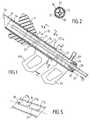
- la figure 1 représente en coupe axiale (avec parties intermédiaires supprimées), un applicateur selon l'invention dans la position correspondant à l'introduction d'une prothèse dans l'urètre d'un patient ;
- la figure 2 représente une coupe selon II-II de la figure 1 ;
- la figure 3 représente, en perspective, une prothèse selon l'invention dans la conformation tubulaire correspondant à sa mise en place ;
- les figures 4a, 4b, 4c représentent, en perspective, trois conformations de prothèse selon l'invention à l'état libre, l'axe de la conformation tubulaire telle que représentée sur la figure 3 étant figuré en traits mixtes ;
- la figure 5 représente, en perspective, une vue selon V-V de la figure 1.
- FIG. 1 shows in axial section (with intermediate parts removed), an applicator according to the invention in the position corresponding to the introduction of a prosthesis into the urethra of a patient;
- Figure 2 shows a section on II-II of Figure 1;
- FIG. 3 represents, in perspective, a prosthesis according to the invention in the tubular conformation corresponding to its positioning;
- Figures 4a, 4b, 4c show, in perspective, three conformations prosthesis according to the invention in the free state, the axis of the tubular configuration as shown in Figure 3 is figured in phantom;
- FIG. 5 represents, in perspective, a view along VV of FIG. 1.
En se référant au dessin, on voit que l'on a désigné par 14 dans son ensemble une prothèse selon l'invention.Referring to the drawing, it can be seen that a prosthesis according to the invention has been designated by 14 as a whole.
La prothèse 14 est constituée en un matériau plastique biocompatible ; à l'état libre elle peut avoir l'une des formes représentées sur les figures 4a à 4c, c'est-à-dire qu'elle peut être constituée par une paroi plane ou par une gouttière formant un secteur cylindrique. Dans tous les cas, la prothèse 14 est destinée à être conformée pour sa mise en place sous une forme tubulaire comme représenté sur la figure 3. L'axe de la conformation tubulaire est représenté sur les figures 4a à 4c en traits mixtes par rapport à la paroi de la prothèse à l'état libre ; la gouttière est dite concave lorsque l'axe de la conformation tubulaire finale est dans la concavité de la gouttière ; elle est dite convexe dans le cas contraire.The
La prothèse 14 comporte sur chacun de ses bords longitudinaux une succession de pattes 14a et de créneaux 14b de forme sensiblement rectangulaire destinés, lorsque les deux bords longitudinaux de la prothèse sont rapprochés pour obtenir la conformation tubulaire de mise en place représentée sur la figure 3, à constituer un assemblage mâle-femelle, les pattes 14a d'un bord s'emboîtant dans les créneaux 14b de l'autre bord. Dans l'épaisseur de la paroi constitutive de la prothèse 14 et parallèlement à ses bords longitudinaux, on a ménagé dans les pattes 14a des percements 14c, qui, lorsque les deux bords longitudinaux de la prothèse sont rapprochés et assemblés avec emboîtage des pattes 14a dans les créneaux 14b, sont alignés pour permettre le passage d'un fil de maintien ou d'agrafage 21. Le fil 21 maintient la paroi constitutive de la prothèse dans une conformation cylindrique représentée sur la figure 3, conformation dont le diamètre extérieur correspond au diamètre intérieur du logement 20, qui sera défini ci-après. Le fil 21 est destiné à être retiré quand la prothèse a été mise en place à l'endroit désiré dans l'urètre, de façon que la paroi de la prothèse 14 tende élastiquement à revenir à la forme qu'elle avait à l'état libre c'est-à-dire à l'une des formes représentées sur les figures 4a à 4c. Dans le cas d'une forme initiale en gouttière convexe (figure 4c), la concavité de la paroi de la prothèse a été inversée pour la mise en place du fil 21 et la force élastique de retour à la forme initiale est plus grande que dans le cas d'une gouttière concave (figure 4b) ; le cas de la paroi initialement plane (figure 4a) est intermédiaire entre le cas d'une gouttière concave et le cas d'une gouttière convexe. Cette force élastique tendant au retour à la forme initiale assure le maintien de la prothèse dans l'urètre et l'ouverture optimum de la section droite de la zone d'urêtre ou s'effectue la mise en place de la prothèse.The
La prothèse 14 présente, en outre, des extrémités transversales 14d qui sont dans des plans sensiblement perpendiculaires aux bords longitudinaux crénelés ; ces extrémités 14d sont arrondies, l'arrondi permettant une mise en place aisée de la prothèse sans blesser le conduit urétral. La longueur de la prothèse est généralement de l'ordre de 2 à 4 centimètres selon la zone d'urètre à traiter ; son diamètre, quand elle est mise dans sa conformation tubulaire, permet une implantation dans toutes les zones de l'urètre sachant que l'ouverture élastique de la prothèse in situ rattrape les variations de diamètre de l'urètre.The
L'applicateur de prothèse selon l'invention est désigné par 15 dans son ensemble sur la figure 1 ; il comporte essentiellement un introducteur 16 et un piston d'application 17 portant en glissement interne un conduit optique 18 ; un logement 20 de la prothèse 14 est ménagé en amont à l'intérieur dudit introducteur 16, dans le prolongement du piston 17. Le piston 17 est susceptible de coulisser à l'intérieur de l'introducteur 16 ; il comporte intérieurement des nervures 22, qui guident entre elles la mise en place par coulissement du conduit optique 18.The prosthesis applicator according to the invention is designated by 15 as a whole in FIG. 1; it basically has a
L'introducteur 16 constitue une tubulure cylindrique, qui est biseautée en forme de sifflet 19 à son extrémité amont afin de faciliter son introduction dans l'urètre. L'introduteur 16 constitue un fourreau cylindrique, qui peut être métallique, par exemple en titane ou en un alliage similaire de faible épaisseur ; il peut porter une poignée de préhension 121 associée, du côté diamétralement opposé de l'introducteur, à un doigt d'appui 121a.The
Le piston 17 est également un cylindre mince qui peut aussi être métallique ; il comporte intérieurement des nervures axiales 22, rectilignes ou non, par exemple, disposées radialement au nombre de quatre comme il est visible sur la figure 2. Ces nervures guident et maintiennent le conduit optique 18 et permettent sa mise en place par glissement axial à l'intérieur de l'introducteur. Le piston 17 comporte extérieurement une arrivée d'eau 122 et une poignée de préhension 23. Un joint d'étanchéité 24 est disposé entre, d'une part, l'extrémité aval du piston 17 qui est opposé à celle adjacente au logement 20, et d'autre part, la paroi externe du conduit optique 18, pour limiter autant que possible les fuites d'eau.The
On dispose la prothèse 14, mise dans sa conformation tubulaire grâce au fil d'agrafage 21, dans son logement 20, de façon que le fil 21 se place dans un compartiment entre deux nervures adjacentes 22 comme il est visible sur les figures 1 et 2 ; le fil 21 émerge du piston par un orifice 25 où l'on peut également prévoir un joint d'étanchéité. De la sorte, il est possible pour le praticien urologue de tirer sur le fil 21 comme il sera explicité ci-après.The
Enfin, on a prévu sur la paroi latérale de l'introducteur une fente longitudinale crantée 27 à l'intérieur de laquelle se trouve un ergot 26 qui est lié au piston 17. L'ergot 26 peut être positionné dans l'un des crans 27a 27b 27c répartis sur la longueur de la fente 27 par une rotation du piston 17 par rapport à l'introducteur 16. Ceci permet de positionner la prothèse 14 dans son logement 20 en fonction de sa longueur. Bien entendu, il serait possible de mettre en place de simples repères dimensionnels le long de la fente 27 pour obtenir le même résultat. Lorsque l'on veut permettre le coulissement relatif de l'introducteur 16 par rapport au piston 17, il convient, bien entendu, de sortir préalablement l'ergot 26 du cran latéral où il a été positionné de façon à le ramener dans l'axe de la fente 27.Finally, there is provided on the side wall of the introducer a notched
Pour procéder à la mise en place de la prothèse urétrale selon l'invention, on amène la prothèse 14 dans sa conformation tubulaire où les pattes 14a sont positionnées dans les créneaux 14b et on fixe la prothèse dans cette conformation au moyen du fil d'agrafage 21. On met ensuite en place la prothèse 14 dans le logement 20 de l'applicateur 15, le fil 21 dépassant largement vers l'extérieur par l'orifice 25 ; en variant on peut prévoir de disposer le fil 21 à l'intérieur d'une fente longitudinale pratiquée dans l'épaisseur de la paroi de l'introducteur 16. On introduit ensuite dans l'urètre l'extrémité biseautée 19 de l'introducteur 16, l'urologue s'aidant pour cette introduction du conduit optique 18 et des moyens radioscopiques usuels jusqu'à ce que l'on atteigne pour la prothèse 14 la position souhaitée qui peut être dans la région péniène, bulbaire ou prostatique de l'urètre. L'urologue peut ajuster très exactement le positionnement de la prothèse en poussant ou tirant l'introducteur 16 ; quand la localisation désirée a été atteinte de façon précise, le praticien tire vers l'aval, selon la flèche F1, l'applicateur 16 en maintenant sensiblement en position fixe le piston 17 ; de la sorte la prothèse 14 est extraite de son logement 20 ; on tire alors sur le fil 21 selon la flèche F2 pour produire le désagrafage de la prothèse 14 dont la paroi, par élasticité, tend à reprendre sa conformation initiale en s'appuyant élastiquement contre la paroi de l'urètre. La prothèse ainsi mise en place peut, en fonction du conduit urétral, occuper une position plus ou moins ouverte, ses bords longitudinaux étant plus ou moins écartés l'un de l'autre ; au cours du temps la prothèse occupe en raison de son élasticité propre une position optimale qui permet de réaliser dans la zone d'urètre traitée une section maximale pour le passage de l'urine tout en assurant une position stable dans l'urètre, une bonne tolérance par le patient. En outre il est possible sans trop de difficulté d'éliminer ultérieurement la prothèse. On constate donc que la prothèse selon l'invention peut être mise en place de façon très précise grâce à l'applicateur qui a été ci-dessus décrit.To proceed with the placement of the urethral prosthesis according to the invention, the
Claims (13)
Translated fromFrenchApplications Claiming Priority (4)
| Application Number | Priority Date | Filing Date | Title |
|---|---|---|---|
| FR9512426AFR2740024B1 (en) | 1995-10-23 | 1995-10-23 | PROSTHESES OF THE URINARY TREE WITH THEIR APPLICATORS |
| FR9512426 | 1995-10-23 | ||
| FR9609102AFR2740025B1 (en) | 1995-10-23 | 1996-07-19 | URETRAL PROSTHESIS AND ITS ASSOCIATED APPLICATOR |
| FR9609102 | 1996-07-19 |
Publications (2)
| Publication Number | Publication Date |
|---|---|
| EP0770365A2true EP0770365A2 (en) | 1997-05-02 |
| EP0770365A3 EP0770365A3 (en) | 1997-05-07 |
Family
ID=26232276
Family Applications (1)
| Application Number | Title | Priority Date | Filing Date |
|---|---|---|---|
| EP96402243AWithdrawnEP0770365A3 (en) | 1995-10-23 | 1996-10-22 | Urethral prosthesis and instrument for its placement |
Country Status (2)
| Country | Link |
|---|---|
| EP (1) | EP0770365A3 (en) |
| FR (2) | FR2740024B1 (en) |
Cited By (3)
| Publication number | Priority date | Publication date | Assignee | Title |
|---|---|---|---|---|
| WO1999037245A1 (en)* | 1998-01-26 | 1999-07-29 | Arterial Vascular Engineering, Inc. | Endoluminal stents and their manufacture |
| EP0916305A3 (en)* | 1997-11-18 | 1999-08-18 | Bidoia s.a.s. di Gianfranco Bidoia E C. | Device for protecting the tissues of physiological pathways during explorations with diagnostic and/or operating instruments |
| WO2002032321A1 (en)* | 2000-10-19 | 2002-04-25 | Yeung Jeffrey E | Urethral muscle controlled micro-invasive sphincteric closure device |
Citations (3)
| Publication number | Priority date | Publication date | Assignee | Title |
|---|---|---|---|---|
| EP0274846A1 (en) | 1986-12-09 | 1988-07-20 | Boston Scientific Corporation | Apparatus for treating hypertrophy of the prostate gland |
| FR2667783A1 (en) | 1990-10-11 | 1992-04-17 | Berberian Jean Pierre | Urinary tract prosthesis |
| DE4141572A1 (en) | 1991-09-13 | 1993-06-24 | Sachse Hans | Urethral prosthesis made from plastics - has longitudinal slit which enables it to be reduced in diameter for ease of insertion |
Family Cites Families (18)
| Publication number | Priority date | Publication date | Assignee | Title |
|---|---|---|---|---|
| FR2409747A1 (en)* | 1977-11-28 | 1979-06-22 | Rey Pierre | NEW TOTAL OR PARTIAL URETERAL PROSTHESES |
| US4307723A (en)* | 1978-04-07 | 1981-12-29 | Medical Engineering Corporation | Externally grooved ureteral stent |
| DE3525165A1 (en)* | 1985-07-13 | 1987-01-15 | Braun Melsungen Ag | URETARY GUIDE CATHETER |
| US4665918A (en)* | 1986-01-06 | 1987-05-19 | Garza Gilbert A | Prosthesis system and method |
| WO1988005317A1 (en)* | 1987-01-13 | 1988-07-28 | Kuntz David H | Urethral stent |
| FR2611486B1 (en)* | 1987-02-27 | 1989-05-12 | Berberian Jean Pierre | URETRAL PROSTHESIS |
| SE8803444D0 (en)* | 1988-09-28 | 1988-09-28 | Medinvent Sa | A DEVICE FOR TRANSLUMINAL IMPLANTATION OR EXTRACTION |
| US4957479A (en)* | 1988-10-17 | 1990-09-18 | Vance Products Incorporated | Indwelling ureteral stent placement apparatus |
| GB2227175B (en)* | 1988-12-09 | 1992-07-22 | David Sydney Grantham | Prosthetic device for relieving prostatic problems |
| US5405379A (en)* | 1990-07-26 | 1995-04-11 | Lane; Rodney J. | Self expanding vascular endoprosthesis for aneurysms |
| SE503249C2 (en)* | 1991-06-14 | 1996-04-29 | Ams Medinvent Sa | Apparatus for transluminal implantation of a substantially tubular, radially expandable stent |
| FR2688688A1 (en)* | 1992-03-12 | 1993-09-24 | Richard Thierry | Tool for fitting an autoexpansible endoprosthesis for human or animal tubular organ |
| US5224953A (en)* | 1992-05-01 | 1993-07-06 | The Beth Israel Hospital Association | Method for treatment of obstructive portions of urinary passageways |
| DE4221087A1 (en)* | 1992-06-26 | 1994-01-05 | Gercke Hans Hermann | Plastics hose shunt for medicinal use - comprises tensioned plastics hose in omega or spiral form having rounded conical tips on ends with circumferential grooves |
| DE9209908U1 (en)* | 1992-07-23 | 1992-09-17 | Neuss, Malte, Dipl.-Ing. (FH), 5300 Bonn | Stripping aid for spiral implants arranged on a guide wire |
| US5306294A (en)* | 1992-08-05 | 1994-04-26 | Ultrasonic Sensing And Monitoring Systems, Inc. | Stent construction of rolled configuration |
| FR2694688B1 (en)* | 1992-08-11 | 1994-11-10 | Novadis Sarl | Expandable tubular prosthesis. |
| DE59208901D1 (en)* | 1992-12-20 | 1997-10-16 | Schneider Europ Ag | Device for implanting an endoprosthesis |
- 1995
- 1995-10-23FRFR9512426Apatent/FR2740024B1/ennot_activeExpired - Fee Related
- 1996
- 1996-07-19FRFR9609102Apatent/FR2740025B1/ennot_activeExpired - Fee Related
- 1996-10-22EPEP96402243Apatent/EP0770365A3/ennot_activeWithdrawn
Patent Citations (4)
| Publication number | Priority date | Publication date | Assignee | Title |
|---|---|---|---|---|
| EP0274846A1 (en) | 1986-12-09 | 1988-07-20 | Boston Scientific Corporation | Apparatus for treating hypertrophy of the prostate gland |
| FR2667783A1 (en) | 1990-10-11 | 1992-04-17 | Berberian Jean Pierre | Urinary tract prosthesis |
| WO1993020779A1 (en) | 1990-10-11 | 1993-10-28 | Berberian Jean Pierre Martial | Urethral prosthesis |
| DE4141572A1 (en) | 1991-09-13 | 1993-06-24 | Sachse Hans | Urethral prosthesis made from plastics - has longitudinal slit which enables it to be reduced in diameter for ease of insertion |
Cited By (5)
| Publication number | Priority date | Publication date | Assignee | Title |
|---|---|---|---|---|
| EP0916305A3 (en)* | 1997-11-18 | 1999-08-18 | Bidoia s.a.s. di Gianfranco Bidoia E C. | Device for protecting the tissues of physiological pathways during explorations with diagnostic and/or operating instruments |
| US6179855B1 (en) | 1997-11-18 | 2001-01-30 | Bidoia S.A.S. Di Gianfranco Bidoia E C. | Device for protecting the tissues of physiological pathways during explorations with diagnostic and/or operating instruments |
| WO1999037245A1 (en)* | 1998-01-26 | 1999-07-29 | Arterial Vascular Engineering, Inc. | Endoluminal stents and their manufacture |
| US6350279B1 (en) | 1998-01-26 | 2002-02-26 | Ave Connaught | Endoluminal stents and their manufacture |
| WO2002032321A1 (en)* | 2000-10-19 | 2002-04-25 | Yeung Jeffrey E | Urethral muscle controlled micro-invasive sphincteric closure device |
Also Published As
| Publication number | Publication date |
|---|---|
| FR2740024B1 (en) | 1998-01-02 |
| EP0770365A3 (en) | 1997-05-07 |
| FR2740024A1 (en) | 1997-04-25 |
| FR2740025B1 (en) | 1998-06-12 |
| FR2740025A1 (en) | 1997-04-25 |
Similar Documents
| Publication | Publication Date | Title |
|---|---|---|
| EP0440618B1 (en) | Tubular endoprosthesis for anatomical conduits, and instrument for its setting in place | |
| EP1315458B1 (en) | Vascular occlusion device and apparatus for using same | |
| EP0566807B1 (en) | Self expanding vascular endoprosthesis | |
| EP1057457B1 (en) | Biliary shunt prosthesis | |
| EP3373859B1 (en) | Mitral or tricuspid heart valve prosthesis | |
| CA2621583C (en) | Device and method for preventing female stress incontinence | |
| EP1320338B1 (en) | Flexible intraocular implant injector | |
| FR2694688A1 (en) | Expandable tubular prosthesis. | |
| FR2930137A1 (en) | Treatment equipment i.e. annuloplasty equipment, for mitral valve of heart, has connection unit pivoted to slide lateral branches till interconnection position in which ends of central branch are situated at proximity of respective surfaces | |
| FR2701648A1 (en) | Prosthesis intended for the treatment of a light or natural way, in particular endo-urethral prosthesis. | |
| EP0437121A2 (en) | Filter-catheter combination | |
| FR2749500A1 (en) | DEVICE ALLOWING THE TREATMENT OF BODY CONDUITS AT THE LEVEL OF A BIFURCATION | |
| FR2853223A1 (en) | INTRAOCULAR LENS AND ITS INJECTOR | |
| FR2784287A1 (en) | Scleral expanding implant for eye surgery has arcuate strip inserted into eye to enlarge scleral ring | |
| CA2885261C (en) | Endo-urethral prosthesis | |
| FR3087113A1 (en) | AORTIC IMPLANT OF STENT TYPE, AND ASSEMBLY OF TWO SUCH IMPLANTS | |
| EP0079844A1 (en) | Artificial heart valve | |
| EP0770365A2 (en) | Urethral prosthesis and instrument for its placement | |
| FR2588746A1 (en) | WELDENER | |
| FR2946865A1 (en) | DEVICE FOR TREATING A BLOOD CIRCULATION CONDUIT | |
| FR2557460A1 (en) | URETRAL DRAIN AND EQUIPMENT FOR BRIDGING OBSTRUCTIONS IN THE URETRE COMPRISING SUCH A DRAIN | |
| WO1993020779A1 (en) | Urethral prosthesis | |
| EP0906750B1 (en) | Urethral prosthesis | |
| FR3032886A1 (en) | URETERAL PROBE ASSEMBLY AND METHOD OF ASSEMBLY TO MEASURE | |
| FR2944201A1 (en) | BRONCHIC SHUTTER WITH VALVE |
Legal Events
| Date | Code | Title | Description |
|---|---|---|---|
| PUAI | Public reference made under article 153(3) epc to a published international application that has entered the european phase | Free format text:ORIGINAL CODE: 0009012 | |
| PUAL | Search report despatched | Free format text:ORIGINAL CODE: 0009013 | |
| AK | Designated contracting states | Kind code of ref document:A2 Designated state(s):BE CH DE ES FR GB IT LI | |
| AK | Designated contracting states | Kind code of ref document:A3 Designated state(s):BE CH DE ES FR GB IT LI | |
| 17P | Request for examination filed | Effective date:19971007 | |
| 17Q | First examination report despatched | Effective date:20020123 | |
| STAA | Information on the status of an ep patent application or granted ep patent | Free format text:STATUS: THE APPLICATION IS DEEMED TO BE WITHDRAWN | |
| 18D | Application deemed to be withdrawn | Effective date:20020803 |