EP0768091B1 - Artificial heart - Google Patents
Artificial heartDownload PDFInfo
- Publication number
- EP0768091B1 EP0768091B1EP95116289AEP95116289AEP0768091B1EP 0768091 B1EP0768091 B1EP 0768091B1EP 95116289 AEP95116289 AEP 95116289AEP 95116289 AEP95116289 AEP 95116289AEP 0768091 B1EP0768091 B1EP 0768091B1
- Authority
- EP
- European Patent Office
- Prior art keywords
- sealing liquid
- driving shaft
- sealing
- section
- bearing
- Prior art date
- Legal status (The legal status is an assumption and is not a legal conclusion. Google has not performed a legal analysis and makes no representation as to the accuracy of the status listed.)
- Expired - Lifetime
Links
- 238000007789sealingMethods0.000claimsdescription209
- 239000007788liquidSubstances0.000claimsdescription134
- 230000007246mechanismEffects0.000claimsdescription67
- 210000004369bloodAnatomy0.000claimsdescription50
- 239000008280bloodSubstances0.000claimsdescription50
- 230000002093peripheral effectEffects0.000claimsdescription16
- 210000000056organAnatomy0.000claimsdescription14
- OKTJSMMVPCPJKN-UHFFFAOYSA-NCarbonChemical compound[C]OKTJSMMVPCPJKN-UHFFFAOYSA-N0.000claimsdescription9
- 229910010293ceramic materialInorganic materials0.000claimsdescription7
- 239000000463materialSubstances0.000claimsdescription7
- 229910052799carbonInorganic materials0.000claimsdescription6
- 239000007770graphite materialSubstances0.000claimsdescription3
- 238000001816coolingMethods0.000claims1
- 210000000709aortaAnatomy0.000description21
- 102000004169proteins and genesHuman genes0.000description21
- 108090000623proteins and genesProteins0.000description21
- 230000000747cardiac effectEffects0.000description12
- 210000005240left ventricleAnatomy0.000description9
- 230000000694effectsEffects0.000description7
- 239000008187granular materialSubstances0.000description7
- 230000006870functionEffects0.000description6
- FAPWRFPIFSIZLT-UHFFFAOYSA-MSodium chlorideChemical compound[Na+].[Cl-]FAPWRFPIFSIZLT-UHFFFAOYSA-M0.000description5
- 230000008901benefitEffects0.000description5
- 210000000038chestAnatomy0.000description5
- 229920003051synthetic elastomerPolymers0.000description5
- 239000005061synthetic rubberSubstances0.000description5
- 239000010409thin filmSubstances0.000description5
- 239000010408filmSubstances0.000description4
- 238000005461lubricationMethods0.000description4
- 239000002245particleSubstances0.000description4
- 239000013013elastic materialSubstances0.000description3
- 239000010439graphiteSubstances0.000description3
- 229910002804graphiteInorganic materials0.000description3
- 230000001050lubricating effectEffects0.000description3
- 238000012423maintenanceMethods0.000description3
- 230000002035prolonged effectEffects0.000description3
- 239000011780sodium chlorideSubstances0.000description3
- 238000005299abrasionMethods0.000description2
- 230000002411adverseEffects0.000description2
- 239000000919ceramicSubstances0.000description2
- 238000011109contaminationMethods0.000description2
- 238000009792diffusion processMethods0.000description2
- 210000003709heart valveAnatomy0.000description2
- 239000000314lubricantSubstances0.000description2
- 239000007769metal materialSubstances0.000description2
- 230000004048modificationEffects0.000description2
- 238000012986modificationMethods0.000description2
- 239000012466permeateSubstances0.000description2
- 239000000047productSubstances0.000description2
- HTTJABKRGRZYRN-UHFFFAOYSA-NHeparinChemical compoundOC1C(NC(=O)C)C(O)OC(COS(O)(=O)=O)C1OC1C(OS(O)(=O)=O)C(O)C(OC2C(C(OS(O)(=O)=O)C(OC3C(C(O)C(O)C(O3)C(O)=O)OS(O)(=O)=O)C(CO)O2)NS(O)(=O)=O)C(C(O)=O)O1HTTJABKRGRZYRN-UHFFFAOYSA-N0.000description1
- 210000000683abdominal cavityAnatomy0.000description1
- 230000009471actionEffects0.000description1
- 239000003146anticoagulant agentSubstances0.000description1
- 229940127219anticoagulant drugDrugs0.000description1
- 210000000601blood cellAnatomy0.000description1
- 230000036772blood pressureEffects0.000description1
- 210000001124body fluidAnatomy0.000description1
- 239000010839body fluidSubstances0.000description1
- 230000002612cardiopulmonary effectEffects0.000description1
- 230000015556catabolic processEffects0.000description1
- 210000004027cellAnatomy0.000description1
- 230000015271coagulationEffects0.000description1
- 238000005345coagulationMethods0.000description1
- 239000011248coating agentSubstances0.000description1
- 238000000576coating methodMethods0.000description1
- 239000002131composite materialSubstances0.000description1
- 238000010276constructionMethods0.000description1
- 238000006731degradation reactionMethods0.000description1
- 238000000151depositionMethods0.000description1
- 230000005489elastic deformationEffects0.000description1
- 238000005516engineering processMethods0.000description1
- 239000012530fluidSubstances0.000description1
- 229960002897heparinDrugs0.000description1
- 229920000669heparinPolymers0.000description1
- 230000006872improvementEffects0.000description1
- 210000005246left atriumAnatomy0.000description1
- 210000004115mitral valveAnatomy0.000description1
- 231100000989no adverse effectToxicity0.000description1
- 230000000704physical effectEffects0.000description1
- 230000010349pulsationEffects0.000description1
- 238000005086pumpingMethods0.000description1
- 230000001105regulatory effectEffects0.000description1
- 210000005241right ventricleAnatomy0.000description1
- 239000000126substanceSubstances0.000description1
- 239000013589supplementSubstances0.000description1
- 229920003002synthetic resinPolymers0.000description1
- 239000000057synthetic resinSubstances0.000description1
Images


Classifications
- F—MECHANICAL ENGINEERING; LIGHTING; HEATING; WEAPONS; BLASTING
- F04—POSITIVE - DISPLACEMENT MACHINES FOR LIQUIDS; PUMPS FOR LIQUIDS OR ELASTIC FLUIDS
- F04D—NON-POSITIVE-DISPLACEMENT PUMPS
- F04D29/00—Details, component parts, or accessories
- F04D29/66—Combating cavitation, whirls, noise, vibration or the like; Balancing
- F04D29/669—Combating cavitation, whirls, noise, vibration or the like; Balancing especially adapted for liquid pumps
- A—HUMAN NECESSITIES
- A61—MEDICAL OR VETERINARY SCIENCE; HYGIENE
- A61M—DEVICES FOR INTRODUCING MEDIA INTO, OR ONTO, THE BODY; DEVICES FOR TRANSDUCING BODY MEDIA OR FOR TAKING MEDIA FROM THE BODY; DEVICES FOR PRODUCING OR ENDING SLEEP OR STUPOR
- A61M60/00—Blood pumps; Devices for mechanical circulatory actuation; Balloon pumps for circulatory assistance
- A61M60/10—Location thereof with respect to the patient's body
- A61M60/122—Implantable pumps or pumping devices, i.e. the blood being pumped inside the patient's body
- A61M60/165—Implantable pumps or pumping devices, i.e. the blood being pumped inside the patient's body implantable in, on, or around the heart
- A61M60/17—Implantable pumps or pumping devices, i.e. the blood being pumped inside the patient's body implantable in, on, or around the heart inside a ventricle, e.g. intraventricular balloon pumps
- A61M60/174—Implantable pumps or pumping devices, i.e. the blood being pumped inside the patient's body implantable in, on, or around the heart inside a ventricle, e.g. intraventricular balloon pumps discharging the blood to the ventricle or arterial system via a cannula internal to the ventricle or arterial system
- A—HUMAN NECESSITIES
- A61—MEDICAL OR VETERINARY SCIENCE; HYGIENE
- A61M—DEVICES FOR INTRODUCING MEDIA INTO, OR ONTO, THE BODY; DEVICES FOR TRANSDUCING BODY MEDIA OR FOR TAKING MEDIA FROM THE BODY; DEVICES FOR PRODUCING OR ENDING SLEEP OR STUPOR
- A61M60/00—Blood pumps; Devices for mechanical circulatory actuation; Balloon pumps for circulatory assistance
- A61M60/20—Type thereof
- A61M60/205—Non-positive displacement blood pumps
- A61M60/216—Non-positive displacement blood pumps including a rotating member acting on the blood, e.g. impeller
- A61M60/226—Non-positive displacement blood pumps including a rotating member acting on the blood, e.g. impeller the blood flow through the rotating member having mainly radial components
- A61M60/232—Centrifugal pumps
- A—HUMAN NECESSITIES
- A61—MEDICAL OR VETERINARY SCIENCE; HYGIENE
- A61M—DEVICES FOR INTRODUCING MEDIA INTO, OR ONTO, THE BODY; DEVICES FOR TRANSDUCING BODY MEDIA OR FOR TAKING MEDIA FROM THE BODY; DEVICES FOR PRODUCING OR ENDING SLEEP OR STUPOR
- A61M60/00—Blood pumps; Devices for mechanical circulatory actuation; Balloon pumps for circulatory assistance
- A61M60/20—Type thereof
- A61M60/205—Non-positive displacement blood pumps
- A61M60/216—Non-positive displacement blood pumps including a rotating member acting on the blood, e.g. impeller
- A61M60/237—Non-positive displacement blood pumps including a rotating member acting on the blood, e.g. impeller the blood flow through the rotating member having mainly axial components, e.g. axial flow pumps
- A—HUMAN NECESSITIES
- A61—MEDICAL OR VETERINARY SCIENCE; HYGIENE
- A61M—DEVICES FOR INTRODUCING MEDIA INTO, OR ONTO, THE BODY; DEVICES FOR TRANSDUCING BODY MEDIA OR FOR TAKING MEDIA FROM THE BODY; DEVICES FOR PRODUCING OR ENDING SLEEP OR STUPOR
- A61M60/00—Blood pumps; Devices for mechanical circulatory actuation; Balloon pumps for circulatory assistance
- A61M60/40—Details relating to driving
- A61M60/403—Details relating to driving for non-positive displacement blood pumps
- A61M60/408—Details relating to driving for non-positive displacement blood pumps the force acting on the blood contacting member being mechanical, e.g. transmitted by a shaft or cable
- A61M60/411—Details relating to driving for non-positive displacement blood pumps the force acting on the blood contacting member being mechanical, e.g. transmitted by a shaft or cable generated by an electromotor
- A61M60/416—Details relating to driving for non-positive displacement blood pumps the force acting on the blood contacting member being mechanical, e.g. transmitted by a shaft or cable generated by an electromotor transmitted directly by the motor rotor drive shaft
- A—HUMAN NECESSITIES
- A61—MEDICAL OR VETERINARY SCIENCE; HYGIENE
- A61M—DEVICES FOR INTRODUCING MEDIA INTO, OR ONTO, THE BODY; DEVICES FOR TRANSDUCING BODY MEDIA OR FOR TAKING MEDIA FROM THE BODY; DEVICES FOR PRODUCING OR ENDING SLEEP OR STUPOR
- A61M60/00—Blood pumps; Devices for mechanical circulatory actuation; Balloon pumps for circulatory assistance
- A61M60/40—Details relating to driving
- A61M60/403—Details relating to driving for non-positive displacement blood pumps
- A61M60/419—Details relating to driving for non-positive displacement blood pumps the force acting on the blood contacting member being permanent magnetic, e.g. from a rotating magnetic coupling between driving and driven magnets
- A—HUMAN NECESSITIES
- A61—MEDICAL OR VETERINARY SCIENCE; HYGIENE
- A61M—DEVICES FOR INTRODUCING MEDIA INTO, OR ONTO, THE BODY; DEVICES FOR TRANSDUCING BODY MEDIA OR FOR TAKING MEDIA FROM THE BODY; DEVICES FOR PRODUCING OR ENDING SLEEP OR STUPOR
- A61M60/00—Blood pumps; Devices for mechanical circulatory actuation; Balloon pumps for circulatory assistance
- A61M60/40—Details relating to driving
- A61M60/403—Details relating to driving for non-positive displacement blood pumps
- A61M60/422—Details relating to driving for non-positive displacement blood pumps the force acting on the blood contacting member being electromagnetic, e.g. using canned motor pumps
- A—HUMAN NECESSITIES
- A61—MEDICAL OR VETERINARY SCIENCE; HYGIENE
- A61M—DEVICES FOR INTRODUCING MEDIA INTO, OR ONTO, THE BODY; DEVICES FOR TRANSDUCING BODY MEDIA OR FOR TAKING MEDIA FROM THE BODY; DEVICES FOR PRODUCING OR ENDING SLEEP OR STUPOR
- A61M60/00—Blood pumps; Devices for mechanical circulatory actuation; Balloon pumps for circulatory assistance
- A61M60/80—Constructional details other than related to driving
- A61M60/802—Constructional details other than related to driving of non-positive displacement blood pumps
- A61M60/804—Impellers
- A61M60/806—Vanes or blades
- A—HUMAN NECESSITIES
- A61—MEDICAL OR VETERINARY SCIENCE; HYGIENE
- A61M—DEVICES FOR INTRODUCING MEDIA INTO, OR ONTO, THE BODY; DEVICES FOR TRANSDUCING BODY MEDIA OR FOR TAKING MEDIA FROM THE BODY; DEVICES FOR PRODUCING OR ENDING SLEEP OR STUPOR
- A61M60/00—Blood pumps; Devices for mechanical circulatory actuation; Balloon pumps for circulatory assistance
- A61M60/80—Constructional details other than related to driving
- A61M60/802—Constructional details other than related to driving of non-positive displacement blood pumps
- A61M60/81—Pump housings
- A61M60/812—Vanes or blades, e.g. static flow guides
- A—HUMAN NECESSITIES
- A61—MEDICAL OR VETERINARY SCIENCE; HYGIENE
- A61M—DEVICES FOR INTRODUCING MEDIA INTO, OR ONTO, THE BODY; DEVICES FOR TRANSDUCING BODY MEDIA OR FOR TAKING MEDIA FROM THE BODY; DEVICES FOR PRODUCING OR ENDING SLEEP OR STUPOR
- A61M60/00—Blood pumps; Devices for mechanical circulatory actuation; Balloon pumps for circulatory assistance
- A61M60/80—Constructional details other than related to driving
- A61M60/802—Constructional details other than related to driving of non-positive displacement blood pumps
- A61M60/818—Bearings
- A61M60/825—Contact bearings, e.g. ball-and-cup or pivot bearings
- A—HUMAN NECESSITIES
- A61—MEDICAL OR VETERINARY SCIENCE; HYGIENE
- A61M—DEVICES FOR INTRODUCING MEDIA INTO, OR ONTO, THE BODY; DEVICES FOR TRANSDUCING BODY MEDIA OR FOR TAKING MEDIA FROM THE BODY; DEVICES FOR PRODUCING OR ENDING SLEEP OR STUPOR
- A61M60/00—Blood pumps; Devices for mechanical circulatory actuation; Balloon pumps for circulatory assistance
- A61M60/80—Constructional details other than related to driving
- A61M60/802—Constructional details other than related to driving of non-positive displacement blood pumps
- A61M60/827—Sealings between moving parts
- A61M60/829—Sealings between moving parts having a purge fluid supply
- A—HUMAN NECESSITIES
- A61—MEDICAL OR VETERINARY SCIENCE; HYGIENE
- A61M—DEVICES FOR INTRODUCING MEDIA INTO, OR ONTO, THE BODY; DEVICES FOR TRANSDUCING BODY MEDIA OR FOR TAKING MEDIA FROM THE BODY; DEVICES FOR PRODUCING OR ENDING SLEEP OR STUPOR
- A61M60/00—Blood pumps; Devices for mechanical circulatory actuation; Balloon pumps for circulatory assistance
- A61M60/80—Constructional details other than related to driving
- A61M60/855—Constructional details other than related to driving of implantable pumps or pumping devices
- A61M60/871—Energy supply devices; Converters therefor
- A61M60/873—Energy supply devices; Converters therefor specially adapted for wireless or transcutaneous energy transfer [TET], e.g. inductive charging
- F—MECHANICAL ENGINEERING; LIGHTING; HEATING; WEAPONS; BLASTING
- F04—POSITIVE - DISPLACEMENT MACHINES FOR LIQUIDS; PUMPS FOR LIQUIDS OR ELASTIC FLUIDS
- F04D—NON-POSITIVE-DISPLACEMENT PUMPS
- F04D29/00—Details, component parts, or accessories
- F04D29/08—Sealings
- F04D29/10—Shaft sealings
- F04D29/12—Shaft sealings using sealing-rings
- F04D29/126—Shaft sealings using sealing-rings especially adapted for liquid pumps
- F04D29/128—Shaft sealings using sealing-rings especially adapted for liquid pumps with special means for adducting cooling or sealing fluid
- F—MECHANICAL ENGINEERING; LIGHTING; HEATING; WEAPONS; BLASTING
- F04—POSITIVE - DISPLACEMENT MACHINES FOR LIQUIDS; PUMPS FOR LIQUIDS OR ELASTIC FLUIDS
- F04D—NON-POSITIVE-DISPLACEMENT PUMPS
- F04D3/00—Axial-flow pumps
- F04D3/005—Axial-flow pumps with a conventional single stage rotor
- A—HUMAN NECESSITIES
- A61—MEDICAL OR VETERINARY SCIENCE; HYGIENE
- A61M—DEVICES FOR INTRODUCING MEDIA INTO, OR ONTO, THE BODY; DEVICES FOR TRANSDUCING BODY MEDIA OR FOR TAKING MEDIA FROM THE BODY; DEVICES FOR PRODUCING OR ENDING SLEEP OR STUPOR
- A61M2205/00—General characteristics of the apparatus
- A61M2205/82—Internal energy supply devices
- A61M2205/8237—Charging means
- A61M2205/8243—Charging means by induction
- A—HUMAN NECESSITIES
- A61—MEDICAL OR VETERINARY SCIENCE; HYGIENE
- A61M—DEVICES FOR INTRODUCING MEDIA INTO, OR ONTO, THE BODY; DEVICES FOR TRANSDUCING BODY MEDIA OR FOR TAKING MEDIA FROM THE BODY; DEVICES FOR PRODUCING OR ENDING SLEEP OR STUPOR
- A61M60/00—Blood pumps; Devices for mechanical circulatory actuation; Balloon pumps for circulatory assistance
- A61M60/10—Location thereof with respect to the patient's body
- A61M60/122—Implantable pumps or pumping devices, i.e. the blood being pumped inside the patient's body
- A61M60/126—Implantable pumps or pumping devices, i.e. the blood being pumped inside the patient's body implantable via, into, inside, in line, branching on, or around a blood vessel
- A61M60/148—Implantable pumps or pumping devices, i.e. the blood being pumped inside the patient's body implantable via, into, inside, in line, branching on, or around a blood vessel in line with a blood vessel using resection or like techniques, e.g. permanent endovascular heart assist devices
Definitions
- This inventionrelates to an artificial organ, for example an auxiliary artificial heart of an embedded type, embedded in the left or right ventricle of the heart in a human body, and operated at high reliability by preventing body fluids such as blood from adversely entering the artificial heart.
- Conventional artificial heartsare of a diaphragm type, of a sack type, of an axially symmetric type, of a centrifugal type, of a pusher plate type or the like. Each of these conventional artificial hearts delivers blood in place of a human heart or by bypassing it.
- an auxiliary artificial heartwhich is embedded in a ventricle of a human heart and has the tip end of a nozzle passing through an aorta valve or the like such that blood is delivered from the ventricle into an aorta through the nozzle.
- the artificial hearthas such a structure that it does not suppress any function of the human heart when it is provided in the human heart and it delivers additional blood into the aorta when blood pumped out from the human heart due to its beats is insufficient.
- the bloodis delivered not only by the artificial heart but also by the pulsing human heart due to its beats. Even if the operation of the artificial heart happens to stop, blood is delivered by the human heart due to its beats.
- an artificial hearthas a pump body comprising a cylindrical axial-flow pump section, a nozzle section provided on its distal end and a driving section provided on the proximal end of the axial-flow pump section.
- the cardiac apex of a ventricle of a human heartis cut and a short cylindrical cardiac apex ring is embedded therein.
- the pump section and the nozzle sectionare inserted in the ventricle through the cardiac apex ring, and the distal end of the nozzle section is inserted in an aorta through its aorta valve or the like.
- the driving section which has a large volumeis embedded in a portion of the thorax which is outside of the human heart.
- the artificial hearthas the following problem in connection with the function of a shaft-sealing mechanism provided between the pump section and the driving section.
- a motor and other elementsare housed in the driving section, and the rotor of the pump section is driven via driving shaft extending from the driving section to the pump section.
- Blood applied with a blood pressureflows through the pump section. In this state, blood is not allowed to enter the space in the driving section. If blood enters the space defined in the driving section, coagulation of blood occurs and the operation of the motor stops.
- Patent Application No. 94105896.8(EP-A-0 629 412) filed on April 15, 1994 by the applicant of the present patent application discloses such an artificial heart.
- An artificial heart disclosed in the above patent applicationis designed to be inserted in a ventricle of a human heart, including a cylindrical cardiac apex ring embedded in the cardiac apex of the human heart by cutting the cardiac apex, and a main body of the artificial heart comprising a cylindrical axial-flow pump section inserted in the ventricle of the human heart through the cardiac apex ring, a nozzle section extending outward from the distal end of the pump section through the aorta valve of the human heart and a driving section provided on the proximal end of the pump section and disposed outside (or externally) of the human heart, for driving the pump section through a driving shaft.
- the sealing mechanismBetween the driving section and the pump section is provided a sealing mechanism for maintaining the driving shaft in a liquid tight state so as to prevent blood from entering the interior of the driving section from the pump section.
- the sealing mechanismdefines a sealing liquid chamber surrounding the driving shaft at the driving section and a sealing liquid is filled in the sealing liquid chamber.
- the sealing liquidincludes a physiological sodium chloride solution or an anticoagulant such as heparin, and the sealing liquid chamber communicates with a sealing liquid bag made of flexible material, filled with the sealing liquid and embedded in the human body.
- the sealing mechanismis provided with an oil seal made of elastic material, closely fitted on the outer peripheral surface of the driving shaft due to its elastic deformation and forming a lubricating film of the sealing liquid between the peripheral surface of the driving shaft and the oil seal.
- the pump sectionis driven by a motor or the like driving unit housed in the driving section.
- the pump sectionsucks blood from a ventricle of a human heart and discharges it into an aorta from the nozzle section of the distal end of the pump section by bypassing the aorta valve or the like.
- bloodis delivered to the aorta not only by the beats of the human heart but also by means of the artificial heart.
- the artificial heartsupplements insufficient amount of blood which is not provided by the human heart, whereby it is ensured that the necessary amount of blood can be delivered.
- the volume of the pump sectionis smaller than the volume of the ventricle of the human heart when it contract most so as not to prevent natural beats of the human heart.
- the sealing mechanismprevents blood from entering the driving section from the pump section.
- the sealing mechanismdefines a sealing liquid chamber at the driving section, and a sealing liquid such as a physiological sodium chloride solution is filled in the sealing liquid chamber. Sealing and lubrication of the sealing mechanism are ensured by the sealing liquid, and blood is securely prevented from entering the interior of the driving section from the sealing mechanism.
- the sealing mechanismis provided with an oil seal which forms a lubricant film of the dealing liquid between the oil seal and the outer peripheral surface of the driving shaft and is elastically closely fitted on the outer peripheral surface of the driving shaft for securely preventing the entrance of blood such that the oil seal is not worn and has high durability.
- the oil sealcan be designed such that the lubricant film formed between the oil seal and the outer peripheral surface of the driving shaft delivers blood in only one direction toward the pump section. This structure prevents blood from entering the interior of the driving section.
- the sealing liquid chambercommunicates with the sealing liquid bag embedded in the human thorax or the like.
- a sealing liquidis supplemented from the sealing liquid bag and thus can be supplied to the sealing liquid chamber for a long time.
- the driving shaftuses a dynamic pressure bearing made of ceramic material operated in the sealing liquid.
- a coating filmis formed between the sliding surfaces due to the dynamic pressure of the sealing liquid, thereby reducing rotational resistance of the bearing and preventing its wear, leading to high reliability.
- the dynamic pressure bearingWhen the driving shaft is rotated, the dynamic pressure bearing generates dynamic pressure.
- the dynamic pressureprovided a liquid seal between the sealing liquid chamber and the driving section. The sealing liquid is thereby prevented from flowing from the sealing liquid chamber into the driving section.
- the dynamic pressure bearingwhich is mounted on the distal end portion of the driving shaft, supplied the sealing liquid to the oil seal. Hence, the sealing liquid circulates in the artificial heart, preventing foreign body from depositing.
- the above described sealing mechanism of artificial hearthas room for improvement in order to relieve the burden on the part of the patient who carries such an artificial heart. More specifically, since the artificial heart is embedded in the patient's proper heart and remains there for use, the patient's chest has to be opened and the artificial heart has to be taken out for servicing or replacement, imposing a large burden to the patient. Thus, an artificial heart is required to operate reliably for a very long period of time without servicing.
- the oil sealis typically made of an elastic material such as synthetic rubber.
- synthetic rubberthe period guaranteed for the initial physical properties of synthetic rubber is normally specified by the supplier for each product, starting form the cure date of the product.
- the artificial heartcomprising an oil seal of the above described type for its sealing mechanism and embedded in a patient has to be taken out of the patient by cutting his or her chest before the guaranteed period expires.
- a material having such a limited guaranteed periodmay preferably not be used for the sealing mechanism of an artificial heart.
- the period until the next supply of sealing liquid to an embedded artificial heartshould be made as long as possible.
- the patienthas to visit the hospital and see the doctor who carries out the operation of supplying sealing liquid in order to prevent any possible contamination by microbes of the sealing liquid contained in the bag of the patient. Such a visit on the part of the patient would be particularly burdensome when the sealing liquid bag is embedded in the patient.
- the period until the next supply of sealing liquidshould be made as long as possible, although this period can be prolonged by reducing the consumption rate of sealing liquid by the patient.
- a thin film of sealing liquidis normally formed between the oil seal and the sealing surface of the driving shaft to maintain its lubricating and sealing effect.
- some protein in the bloodcan permeate into the thin film by diffusion and become coagulated by the heat generated by the friction between the oil seal and the sealing surface.
- the coagulated proteintakes the form of granules and mostly driven out of the sealing mechanism with sealing liquid being supplied and eventually dispersed into the blood, part of the granules of coagulated protein can adhere to the surface of the oil seal.
- the reliability of the sealing mechanismhas to be improved.
- An artificial heart of the type under consideration and particularly the operation of the sealing mechanismcan be examined only indirectly by checking the consumed volume and the level of contamination of the sealing liquid. If it is found that too much sealing liquid has been consumed unexpectedly and/or the sealing liquid has been contaminated, if to a small extent, replacement of the artificial heart may have to be considered for the sake of safety. This by turn will increase the burden on the part of the patient.
- WO 85/01436discloses a blood pump comprising a rotor and a stator which co-operate to convey a blood stream to the pump. As shown in Fig. 5, there is provided a drive shaft. The rotor is positioned with respect to the stator by a pair of spherical bearings.
- WO 89/04644discloses a miniature high-speed intravascular blood pump according to the preamble portion of claim 1.
- a first object of the present inventionto provide an artificial heart comprising a sealing mechanism made of a material having a practically endless service life to make the artificial heart free from maintenance for a prolonged period of time.
- a second object of the inventionis to provide an artificial heart comprising a sealing mechanism that is protected against degradation of its sealing performance due to a deposit of coagulated protein.
- a third object of the inventionis to provide an artificial heart having an improved reliability.
- an artificial heartcomprising a sealing mechanism for the driving shaft of the artificial heart that includes a mechanical seal.
- the mechanical sealincludes a fixed side seal ring and a rotary side follow ring with the ends of the seat ring and follow ring in close contact with each other so as to rotate freely and also contains a pressing mechanism for pressing the follow ring against a seat ring at a specific pressure.
- An artificial heart according to the inventionalso comprises a sealing liquid chamber surrounding the driving shaft and arranged between the mechanical sealing and the driving section, the sealing liquid chamber being filled with a sealing liquid.
- An artificial heart according to the inventionadditionally comprises pump means for feeding the sealing liquid from the sealing liquid chamber to the mechanical seal.
- An artificial heart according to the invention and having the above described configurationdoes not comprise an oil seal and other components made of synthetic rubber in the sealing mechanism that limits the service life of the artificial heart so that the artificial heart is practically free from maintenance for a prolonged period of time.
- the sliding surfaces of the seat ring and the follow ringare polished and held in close contact with each other and the follow ring is pressed against the seat ring under high pressure to preclude any possibility of adhesion of coagulated protein granules to the sliding surfaces and, therefore, the gap, if any, between the sliding surfaces would not be broadened by adhering coagulated protein granules.
- the consumption rate of sealing liquidwould not rise with time and the period between any two successive supplies of sealing liquid would not be shortened to increase the burden on the part of the patient.
- the sealing mechanism of an artificial heart according to the inventionessentially does not contain any synthetic rubber to improve its reliability in terms of abrasion and wear so that the artificial heart can enjoy a practically endless service life to the patient's benefit.
- the driving shaft, the bearing tube of the driving shaft, the seat ring and other related componentsare made of a ceramic material, which is stable both chemically and dimensionally and highly resistant against abrasion. This makes the artificial heart even more reliable and prolongs its service life.
- the driving shaft and the bearing sectionare integrally formed and the bearing section is slidably engaged with the inner peripheral surface of the bearing tube to support the driving shaft.
- a dynamic pressure generating grooveif formed on the outer peripheral surface of the bearing section so that sealing liquid is introduced into the gap between the outer peripheral surface of the bearing section and the inner peripheral surface of the bearing tube to ensure lubrication therebetween.
- the dynamic pressure generating grooveis asymmetrical relative to the axial direction of the driving shaft so that it operates as a pump for feeding sealing liquid axially up to the mechanical seal at a very low rate.
- FIG. 1shows an artificial heart of this invention in a state embedded in the left ventricle B of the heart A of a patient (hereinafter referred to as the "human heart").
- a cardiac apex, a left atrium, a mitral valve, an aorta valve and an aortaare designated by C, D, E, F and G, respectively.
- the artificial heart 1comprises a cardiac valve ring 2 and the main body 3 of the artificial heart.
- the cardiac valve ring 2is a short cylindrical member having a flange and is embedded in the human heart A through the cardiac apex C of the human heart A after the cardiac apex C has been cut.
- the main body 3 of the artificial heart 1comprises a pump section 104, a nozzle section 122 provided on the distal end of the pump section 104 and a driving section 105 provided on the proximal end of the pump section 104.
- the pump section 104 and the nozzle section 122are inserted in the left ventricle B through the cardiac apex ring 2, and the nozzle section 122 is further inserted in the aorta G through the central portion of the aorta valve F. Liquid tightness is ensured between the cardiac apex ring 2 and the main body 3 by means of a ordinary sealing mechanism, for example, a sealing member 8.
- the pump section 104is a relatively small cylindrical member and it has a smaller volume than the volume of the left ventricle B when it contracts most so as not to prevent natural beats of the human heart A.
- a small axial-flow pumpwhich is driven by a motor provided in the driving section 105.
- the pump section 104sucks blood from the left ventricle B at a suction port formed in the outer peripheral surface of the section 104 and discharges the blood from the distal end of the nozzle section 122 into the aorta G with the aorta valve F bypassed.
- the nozzle section 122 passing through the central portion of the aorta valve Fis made of soft synthetic resin material such that it does not suppress the function of the aorta valve F and it does not injure the aorta valve F.
- the driving section 105is embedded in a portion of the thorax outside of the human heart A.
- a motor and other elementssuch as electric cells and electronic control elements if they are required.
- the driving section 105is connected by means of electric wires 9 to a noncontact type electrode 10 embedded in a portion of the human body close to his skin H. A necessary electric power is supplied from an external electric source (not shown) to the driving section 105 through the electrode 10.
- a motor 106is provided in the driving section 105.
- the motor 106is a canned motor where a rotor is housed in a casing filled with liquid.
- Numeral 107indicate a stator coil and 108 a rotor.
- the spacing between the rotor 108 and the casing, or an air gap 109is designed to allow a sealing liquid to circulate.
- a sealing liquid inlet 110 and a sealing liquid outlet 111are made. They are connected to a seal liquid bag 112 via flexible circulation tubes 114, 115, respectively. Then, the sealing liquid circulates between the sealing liquid bag 112 and the inside of the artificial heart. In the sealing liquid bag 112, there is provided a filter, which removes foreign matter mixed in the circulating sealing liquid.
- the pump section 104contains a thin-wall, cylindrical tube section 120 and a casing section 121 formed at the tip portion of the tube section.
- a pump rotorcomposed of a rotor boss 123 and a plurality of rotor blades 124 provided on the boss so as to project from around the boss is housed.
- the pump rotoris rotated by the motor 106.
- Numeral 128indicates a spinner that provides flow straightening.
- the casing section 121there are also provided a plurality of stator vanes 125 and a plurality of front stator vanes also serving as a stay for the casing section 121.
- a fluid inlet 127is made, through which the blood in the left ventricle of the heart is sucked.
- the bloodis discharged from the distal end of a nozzle section 122.
- the nozzle section 122is inserted in the aorta through the aorta valve of the heart.
- the number of the stator vanes 125, 126 and that of rotor blades 124are set at values that do not contain the common factors or integral multiples of the common factors, that is, at prime factors with respect to each other, which thereby prevents the resonance of pulsation of blood sent by rotation of the rotor blades 124.
- numeral 130indicates a driving shaft.
- the base end portion of the driving shaft 130is connected to the rotor 108 of the motor 106.
- the tip end portion of the shaftis connected integrally to the rotor boss 123 of the pump rotor, which is driven via the driving shaft 130.
- a cylindrical bearing tube 131is housed in the tube section 120 of the pump section 104.
- the driving shaft 130is inserted in the bearing tube 131.
- a mechanical sealing mechanism 132 acting as a sealing mechanismis provided.
- the mechanical sealing mechanism 132presents the blood in the left ventricle of the heart from entering the inside the artificial heart.
- a flange-like fixed-side seat ring 133is formed at the tip portion of the bearing tube 131.
- the end of the seat ring 133is worked precisely so as to have a smooth surface perpendicular to the rotation axis of the driving shaft 130 and provides a sealing surface.
- a rotary-side follow ring 134is in close contact with the sealing surface of the seat ring 133 so as to rotate freely, thereby maintaining the effect of sealing.
- the follow ring 134has a disk shape and is provided integrally at the tip portion of the driving shaft 130 so as to be precisely perpendicular to the rotation axis of the driving shaft.
- bearing sections 135 and 136are integrally formed, respectively. These bearing sections 135, 136 are cylindrical and supported by the inner surface of the bearing tube 131 so as to rotate freely. The outer surface of these bearing sections 135, 136 and the inner surface of the bearing tube 131 are worked precisely. These bearing sections 135, 136 and bearing tube 131 support the driving shaft 130 precisely so as to rotate freely.
- spiral shallow dynamic-pressure grooves 140are made in the outer surface of these bearing sections 135, 136.
- These dynamic-pressure grooves 140when the driving shaft 130 rotates, introduces the sealing liquid into the spacing between the outer surface of these bearing sections 135, 136 and the inner surface of the bearing tube 131, thereby assuring the lubrication between them, and allows the sealing liquid to flow toward the tip portion at a specific rate. Therefore, these bearing sections 135, 136 and bearing tube 131 constitute a one-way dynamic-pressure bearing that functions as both of a bearing for supporting the driving shaft 130 and a pump for feeding the sealing liquid.
- the driving shaft 130is not restricted in the direction of the axis with respect to the bearing tube 131, but can move freely in the axis direction.
- a ring-shaped permanent magnet 145is provided on the fixed-side of the housing of the driving section.
- a ring-shaped permanent magnet 146is also provided on the rotor 108 of the motor 106, that is, on the driving shaft 130 side.
- These permanent magnets 145, 146face each other with a specific distance between them. The polarity of these permanent magnets 145, 146 is set so that they may repel one another in the axis direction.
- the spacing between the bearing tube 131 and the driving shaft 130is designed to be sealing liquid chambers 137, 138 through which the sealing liquid circulates.
- the sealing liquid chamber 138is isolated from the outside, that is, the blood passageway in left ventricle of the heart by the mechanical sealing mechanism 132, thereby maintaining the effect of sealing.
- a circulation passage 142is made in the outer portion of the tube section 120 of the pump section 104.
- the tip portion of the circulation passage 142is connected to the sealing liquid chamber 138 and its base end portion is connected to the sealing liquid outlet 111. Therefore, the sealing liquid flows from the sealing liquid bag 112 through the circulation tube 114 and sealing liquid inlet 110 into the air gap 109 of the motor 106. Then, by the pumping action of the one-way dynamic-pressure bearing composed of the bearing sections 135, 136 and bearing tube 131, the sealing liquid is sent through the sealing liquid chambers 137, 138 toward the back of the mechanical sealing mechanism 132 at a specific pressure. The sealing liquid fed to the sealing liquid chamber 138 is returned to the sealing liquid bag 112 via the circulation passage 142, sealing liquid outlet 111, circulation tube 115, and filter 113, and circulates in this route.
- the function and advantage of the first embodiment described aboveare as follows. First, with the one-way dynamic-pressure bearings 135, 136 feed the sealing liquid to the sealing liquid chamber 138 at a specific pressure.
- the sealing liquidforms a thin film of 0.5 to 1.0 ⁇ m in thickness between the seat ring 133 of the mechanical sealing mechanism 132 and the sealing surface of the follow ring 134.
- the thin filmeffects lubrication and sealing between the seat ring and the follow ring. This presents blood from entering the sealing liquid chamber 138, or the inside of the artificial heart.
- the coagulated proteinmay cohere at the inner peripheral edge portions of the seat ring 133 and follow ring 134, such protein particles will be washed away by the sealing liquid circulating inside the mechanical sealing mechanism 134, or inside the sealing liquid chamber 138. Those protein particles are captured by the filter 113 in the sealing liquid bag 112, so that the sealing liquid will never be contaminated.
- the first embodiment using the mechanical sealing mechanism as the sealing mechanismhas the following advantages, as compared with the previous artificial heart using an oil seal as the sealing mechanism.
- an oil sealhas a simple structure and keeps excellently close contact with the driving shaft, when protein in the blood diffuses between the oil seal and the peripheral surface of the driving shaft and coagulates there, the coagulated protein will not be discharged by centrifugal force as described above because the oil seal is in contact with the peripheral surface of the driving shaft. Furthermore, since the oil seal has a high flexibility, when the coagulated protein deposits between the peripheral surface of the driving shaft and the oil seal, the internal diameter of the oil seal extends easily, increasing the spacing between the peripheral surface of the driving shaft and the oil seal. The increase in the spacing increases a flow rate of sealing liquid flowing outside through the spacing.
- the flow of the sealing liquidwashes away the coagulated protein into the blood, resulting in an increase in the amount of sealing liquid flowing outside, or the consumption of sealing liquid. This makes it necessary to frequently supply sealing liquid to the sealing liquid bag, imposing a heavier burden on the patient.
- the sealing liquid circulated as described abovecools the mechanical sealing mechanism 132, effectively preventing part of the mechanism from being locally heated to high temperatures due to sliding friction. This prevents the blood cells from being destroyed as a result of the blood touching high-temperature portions.
- such a mechanical sealhas a higher durability than the oil seal, because the seat ring and follow ring are made of ceramic material or metal material.
- the bearing tube 131 and driving shaft 130 constituting the mechanical sealing mechanismare formed of fine ceramic material, and the follow ring 134 is formed of carbon graphite material, they are precision ground.
- the above-described ceramic materialis chemically stable and superior in dimensional stability.
- the bearing tube 131 and the seat ring 133 as well as the driving shaft 130 and the bearing sections 135, 136are formed integrally, so that the dimensional accuracy of their assembly or the mechanical sealing mechanism is high. Consequently, the accuracy of the positional relationship, such as the perpendicularity or concentricity of the seat ring 133 and follow ring 134 with respect to the rotation axis, is high, assuring a high reliability.
- the follow ring 134is formed of carbon graphite, it matches the seat ring 133 well. Additionally, the carbon graphite has self-lubricating properties, the coefficient of friction is low.
- the materials for these membersare not restricted to what have been described above, but may be suitable combinations of various types of ceramic, carbon graphite, composite material, metal material, and others.
- the follow ring 134is pressed against the seat ring 133 in the mechanical sealing mechanism 132 by magnetic repulsion of the permanent magnets 145, 146, resulting in a simpler configuration and a higher reliability.
- the urging pressuremay come from the attraction between the permanent magnets.
- FIGS. 5 and 6show a second embodiment of the present invention.
- the second embodimentis the same as the first embodiment except for part of the mechanical sealing mechanism and part of the circulation route of the sealing liquid.
- a driving shaft 230 and bearing members 235, 236are formed into separate members.
- the bearing member 235 on the base end sideis supported by a bearing sleeve 240, and the bearing member 236 on the tip end side is supported by a short bearing tube 231.
- a flange section 243is formed, thereby constituting a thrust bearing.
- a passageway 241is formed between the outer surface of the bearing sleeve 240 and the housing of the driving section 5.
- a passageway 242is also formed between the inner surface of the bearing section 236 on the tip end side and the driving shaft 230.
- the sealing liquidpasses through these passageways and circulates through the sealing liquid chambers 137, 138.
- a sealing liquid circulating pump 250is provided outside the body or inside the abdominal cavity of the patient, and the pump 250 circulates the sealing liquid.
- a flange-like seat ring 133is formed integrally.
- the follow ring 134is in close contact with the sealing surface of the end of the seat ring 133.
- the follow ring 134is a member separate from the driving shaft 230.
- the follow ring 134is installed on the rotor boss 223 of the pump rotor.
- the rotor boss 223is designed to move freely a specific distance in the axis direction with respect to the driving shaft 230.
- the follow ring 134can move to some extent in the axis and the diameter direction with respect to the driving shaft 230.
- An O ringprovides sealing between the follow ring 134 and the driving shaft 230.
- the rotor boss 223is hollow and houses a pair of disk-shaped permanent magnets 263, 264 in it.
- One permanent magnet 263is mounted on the rotor boss 223 and the other permanent magnet 264 is mounted on the driving shaft 230.
- the polarity of these permanent magnets 263, 264is set so that they may repel each other. The force of repulsion presses the follow ring 134 against the end of the seat ring 133.
- the driving shaft 230, rotor boss 223, and follow ring 134can move from each other. A relative movement between them can absorb vibrations caused by their rotation. This enables the follow ring 134 to be pressed against the end of the seat ring 133 more stably, resulting in an increase in the reliability of the mechanical sealing mechanism 132.
- the sealing liquidis circulated by the sealing liquid circulating pump 250, the circulating flow rate and pressure of the sealing liquid can be regulated freely.
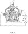
- FIG. 7shows an artificial heart according to a third embodiment of the invention.
- This artificial heartis equipped with a centrifugal pump, and located in a cavity outside the heart of a human body or outside the cavity.
- the artificial hearthas an impeller 305 serving as the centrifugal pump, which is to be driven by a motor 106. Blood is introduced through an inlet nozzle 304 via a catheter, pressurized by the impeller 305, and supplied into the aorta, etc. via an output nozzle 303 and a catheter.
- a clearance between a pump portion which houses the impeller 305 and a motor portion which houses the motor 106is sealed with a sealing mechanism 132 similar to the aforementioned one to prevent the flow of blood into the motor portion.
- a seal liquidsuch as physiologic saline is circulated via a sealing liquid chamber 138 by means of a sealing liquid circulating mechanism similar to the aforementioned one.
- the sealing mechanism 132 employed in the fourth embodimentis similar to those employed in the first and second embodiments, the former has the following structural differences since the artificial heart of the third embodiment can be made larger than the above-described embedded-type artificial heart and hence can be designed more freely in size than the same:
- the motor 106 and the impeller 305are coupled to each other by means of a driving shaft 306 on which a cylindrical shaft member 301 made of ceramics is fitted. Accordingly, the cylindrical shaft member 301 rotates together with the driving shaft 306.
- a driven ring 134is formed integral with an end portion of the shaft member 301 such that it tightly contacts a seat ring 133, which is formed on an end surface of a bearing tube 131, by means of the magnetic forces of permanent magnets 145 and 146.
- An axial sealing liquid passage 302is formed in a center portion of the driving shaft 306, for allowing the sealing liquid to be supplied into the sealing liquid chamber 138 therethrough.
- the sealing mechanism 132 employed in the artificial heart of the third embodimenthas the same function and advantage as the first through and second embodiments.
- the artificial heart of the third embodiment, located outside the heart,is less restricted by size than the embedded-type artificial heart, and needs less reliability than the same.
- the artificial heart of the third embodimentis also requested to have low sealing liquid consumption and high reliability.
- the above-described sealing mechanismsufficiently satisfies the requests.
- the present inventionis not limited to the above-described artificial hearts, but can be applicable to artificial hearts of other types and to an artificial organ having a blood circulating portion, such as an artificial cardiopulmonary organ.
Landscapes
- Health & Medical Sciences (AREA)
- Engineering & Computer Science (AREA)
- Heart & Thoracic Surgery (AREA)
- Mechanical Engineering (AREA)
- Cardiology (AREA)
- Hematology (AREA)
- Anesthesiology (AREA)
- Biomedical Technology (AREA)
- Life Sciences & Earth Sciences (AREA)
- Animal Behavior & Ethology (AREA)
- General Health & Medical Sciences (AREA)
- Public Health (AREA)
- Veterinary Medicine (AREA)
- General Engineering & Computer Science (AREA)
- Computer Networks & Wireless Communication (AREA)
- External Artificial Organs (AREA)
- Prostheses (AREA)
Description
- This invention relates to an artificial organ, forexample an auxiliary artificial heart of an embeddedtype, embedded in the left or right ventricle of theheart in a human body, and operated at high reliabilityby preventing body fluids such as blood from adverselyentering the artificial heart.
- Conventional artificial hearts are of a diaphragmtype, of a sack type, of an axially symmetric type, ofa centrifugal type, of a pusher plate type or the like.Each of these conventional artificial hearts deliversblood in place of a human heart or by bypassing it.
- Recently, there has been developed an auxiliaryartificial heart which is embedded in a ventricle of ahuman heart and has the tip end of a nozzle passingthrough an aorta valve or the like such that blood isdelivered from the ventricle into an aorta through thenozzle. The artificial heart has such a structure thatit does not suppress any function of the human heartwhen it is provided in the human heart and it deliversadditional blood into the aorta when blood pumped outfrom the human heart due to its beats is insufficient.The blood is delivered not only by the artificial heartbut also by the pulsing human heart due to its beats.Even if the operation of the artificial heart happensto stop, blood is delivered by the human heart due toits beats.
- Naturally, the volume of the part of theartificial heart which is inserted in a ventricle ofthe human heart must be smaller than the volume ofthe human heart when it is contracted most. Suchan artificial heart has a pump body comprising acylindrical axial-flow pump section, a nozzle sectionprovided on its distal end and a driving sectionprovided on the proximal end of the axial-flow pumpsection. The cardiac apex of a ventricle of a humanheart is cut and a short cylindrical cardiac apex ringis embedded therein. The pump section and the nozzlesection are inserted in the ventricle through thecardiac apex ring, and the distal end of the nozzlesection is inserted in an aorta through its aorta valveor the like. The driving section which has a largevolume is embedded in a portion of the thorax which isoutside of the human heart.
- The artificial heart has the following problemin connection with the function of a shaft-sealingmechanism provided between the pump section and thedriving section. With artificial heart, a motor andother elements are housed in the driving section, andthe rotor of the pump section is driven via drivingshaft extending from the driving section to the pumpsection. Blood applied with a blood pressure flowsthrough the pump section. In this state, blood is notallowed to enter the space in the driving section. Ifblood enters the space defined in the driving section,coagulation of blood occurs and the operation of themotor stops.
- It is necessary to provide, between the drivingsection and the pump section, a sealing mechanism forsealing the driving shaft in liquid tight state inorder to prevent blood from entering the interior ofthe driving section. Since, however, the artificialheart is embedded in a human body, the artificial heartmust be operated for a long time without maintenance. It is not easy with the present technology to provide ashaft-sealing mechanism with which perfect sealing ismaintained for a long time.
- In order to dissolve the above identifiedproblems, the inventors of the present invention havedeveloped an artificial heart provided with an improvedsealing mechanism for the driving shaft thereof.Patent Application No. 94105896.8 (EP-A-0 629 412) filed on April 15,1994 by the applicant of the present patent applicationdiscloses such an artificial heart. An artificialheart disclosed in the above patent application isdesigned to be inserted in a ventricle of a humanheart, including a cylindrical cardiac apex ringembedded in the cardiac apex of the human heart bycutting the cardiac apex, and a main body of theartificial heart comprising a cylindrical axial-flowpump section inserted in the ventricle of the humanheart through the cardiac apex ring, a nozzle sectionextending outward from the distal end of the pumpsection through the aorta valve of the human heart anda driving section provided on the proximal end of thepump section and disposed outside (or externally) ofthe human heart, for driving the pump section through adriving shaft.
- Between the driving section and the pump sectionis provided a sealing mechanism for maintaining thedriving shaft in a liquid tight state so as to preventblood from entering the interior of the driving sectionfrom the pump section. The sealing mechanism defines asealing liquid chamber surrounding the driving shaft atthe driving section and a sealing liquid is filled inthe sealing liquid chamber.
- The sealing liquid includes a physiological sodiumchloride solution or an anticoagulant such as heparin,and the sealing liquid chamber communicates with asealing liquid bag made of flexible material, filledwith the sealing liquid and embedded in the human body.
- The sealing mechanism is provided with an oil sealmade of elastic material, closely fitted on the outerperipheral surface of the driving shaft due to itselastic deformation and forming a lubricating film ofthe sealing liquid between the peripheral surface ofthe driving shaft and the oil seal.
- The pump section is driven by a motor or the likedriving unit housed in the driving section. The pumpsection sucks blood from a ventricle of a human heartand discharges it into an aorta from the nozzle sectionof the distal end of the pump section by bypassing theaorta valve or the like. Thus, blood is delivered tothe aorta not only by the beats of the human heart butalso by means of the artificial heart. The artificialheart supplements insufficient amount of blood which isnot provided by the human heart, whereby it is ensuredthat the necessary amount of blood can be delivered.The volume of the pump section is smaller than thevolume of the ventricle of the human heart when itcontract most so as not to prevent natural beats of thehuman heart.
- The sealing mechanism prevents blood from enteringthe driving section from the pump section. In thiscase, the sealing mechanism defines a sealing liquidchamber at the driving section, and a sealing liquidsuch as a physiological sodium chloride solution isfilled in the sealing liquid chamber. Sealing andlubrication of the sealing mechanism are ensured by thesealing liquid, and blood is securely prevented fromentering the interior of the driving section from thesealing mechanism.
- Even if the sealing mechanism is deteriorated andblood enters the mechanism, the blood which has enteredthe mechanism is mixed with the sealing liquid. Thus,blood is not coagulated and does not prevent the smoothoperation of the artificial heart.
- The sealing mechanism is provided with an oil seal which forms a lubricant film of the dealing liquidbetween the oil seal and the outer peripheral surfaceof the driving shaft and is elastically closely fittedon the outer peripheral surface of the driving shaftfor securely preventing the entrance of blood such thatthe oil seal is not worn and has high durability. Theoil seal can be designed such that the lubricant filmformed between the oil seal and the outer peripheralsurface of the driving shaft delivers blood in onlyone direction toward the pump section. This structureprevents blood from entering theinterior of the driving section.
- The sealing liquid chamber communicates with thesealing liquid bag embedded in the human thorax orthe like. A sealing liquid is supplemented from thesealing liquid bag and thus can be supplied to thesealing liquid chamber for a long time.
- The driving shaft uses a dynamic pressure bearingmade of ceramic material operated in the sealingliquid. A coating film is formed between the slidingsurfaces due to the dynamic pressure of the sealingliquid, thereby reducing rotational resistance of thebearing and preventing its wear, leading to highreliability.
- When the driving shaft is rotated, the dynamicpressure bearing generates dynamic pressure. Thedynamic pressure provided a liquid seal between thesealing liquid chamber and the driving section. Thesealing liquid is thereby prevented from flowing fromthe sealing liquid chamber into the driving section.
- The dynamic pressure bearing, which is mounted onthe distal end portion of the driving shaft, suppliedthe sealing liquid to the oil seal. Hence, the sealingliquid circulates in the artificial heart, preventingforeign body from depositing.
- On the other hand, the above described sealingmechanism of artificial heart has room for improvement in order to relieve the burden on the part of thepatient who carries such an artificial heart. Morespecifically, since the artificial heart is embedded inthe patient's proper heart and remains there for use,the patient's chest has to be opened and the artificialheart has to be taken out for servicing or replacement,imposing a large burden to the patient. Thus, anartificial heart is required to operate reliably for avery long period of time without servicing.
- While the above described sealing mechanismcomprising an oil seal operates satisfactorily interms of the sealing effect, it remains to be improvedparticularly in the following aspects.
- Firstly, the durability of the material used inthe sealing mechanism. The oil seal is typically madeof an elastic material such as synthetic rubber. Ofcourse, there are a number of elastic materials havinga sufficient durability. However, as for syntheticrubber, the period guaranteed for the initial physicalproperties of synthetic rubber is normally specified bythe supplier for each product, starting form the curedate of the product.
- This means that the artificial heart comprising anoil seal of the above described type for its sealingmechanism and embedded in a patient has to be taken outof the patient by cutting his or her chest before theguaranteed period expires. Thus, a material havingsuch a limited guaranteed period may preferably not beused for the sealing mechanism of an artificial heart.
- Secondly, the period until the next supply ofsealing liquid to an embedded artificial heart shouldbe made as long as possible. The patient has to visitthe hospital and see the doctor who carries out theoperation of supplying sealing liquid in order toprevent any possible contamination by microbes of thesealing liquid contained in the bag of the patient.Such a visit on the part of the patient would be particularly burdensome when the sealing liquid bag isembedded in the patient. Thus, the period until thenext supply of sealing liquid should be made as long aspossible, although this period can be prolonged byreducing the consumption rate of sealing liquid by thepatient.
- If an oil seal is used as described above, theconsumption rate of sealing liquid can rise after along use. A thin film of sealing liquid is normallyformed between the oil seal and the sealing surface ofthe driving shaft to maintain its lubricating andsealing effect. However, some protein in the blood canpermeate into the thin film by diffusion and becomecoagulated by the heat generated by the frictionbetween the oil seal and the sealing surface. Whilethe coagulated protein takes the form of granules andmostly driven out of the sealing mechanism with sealingliquid being supplied and eventually dispersed into theblood, part of the granules of coagulated protein canadhere to the surface of the oil seal. Now, since thelip section of the oil seal is apt to be enlarged bysmall force, granules of coagulated protein can easilybe deposited there to broaden the gap between the oilseal and the sealing surface of the driving shaft andconsequently raise the flow rate of sealing liquidrunning through the gap. The net result will be thatthe time up to the next supply of sealing liquid iscurtailed to put more burden on the patient.
- Thirdly, the reliability of the sealing mechanismhas to be improved. An artificial heart of the typeunder consideration and particularly the operation ofthe sealing mechanism can be examined only indirectlyby checking the consumed volume and the level ofcontamination of the sealing liquid. If it is foundthat too much sealing liquid has been consumedunexpectedly and/or the sealing liquid has beencontaminated, if to a small extent, replacement of the artificial heart may have to be considered for the sakeof safety. This by turn will increase the burden onthe part of the patient.
- WO 85/01436 discloses a blood pump comprising a rotor anda stator which co-operate to convey a blood stream to thepump. As shown in Fig. 5, there is provided a driveshaft. The rotor is positioned with respect to the statorby a pair of spherical bearings.
- WO 89/04644 discloses a miniature high-speed intravascularblood pump according to the preamble portion of claim 1.
- In view of the above circumstances, it istherefore a first object of the present invention toprovide an artificial heart comprising a sealingmechanism made of a material having a practicallyendless service life to make the artificial heartfree from maintenance for a prolonged period of time.A second object of the invention is to provide anartificial heart comprising a sealing mechanism thatis protected against degradation of its sealingperformance due to a deposit of coagulated protein.A third object of the invention is to provide anartificial heart having an improved reliability.
- These objects are solved by an artificial organ according toclaim 1. The sub-claims contain preferred embodiments of the invention.
- According to the present invention, the aboveobjects and other object of the invention are achievedby providing an artificial heart comprising a sealingmechanism for the driving shaft of the artificial heartthat includes a mechanical seal. The mechanical sealincludes a fixed side seal ring and a rotary sidefollow ring with the ends of the seat ring and followring in close contact with each other so as to rotatefreely and also contains a pressing mechanism forpressing the follow ring against a seat ring at aspecific pressure.
- An artificial heart according to the inventionalso comprises a sealing liquid chamber surroundingthe driving shaft and arranged between the mechanicalsealing and the driving section, the sealingliquid chamber being filled with a sealing liquid.An artificial heart according to the inventionadditionally comprises pump means for feeding thesealing liquid from the sealing liquid chamber to themechanical seal.
- An artificial heart according to the inventionand having the above described configuration does not comprise an oil seal and other components made ofsynthetic rubber in the sealing mechanism that limitsthe service life of the artificial heart so that theartificial heart is practically free from maintenancefor a prolonged period of time.
- In the mechanical seal, the ends of the seat ringand follow ring in close contact with each other so asto rotate freely and provide sealing surfaces. Thus,a thin film of sealing liquid is formed between thesealing surfaces to produce a lubricating and sealingeffect. With this arrangement, any foreign objectsthat may exist between the sealing surfaces aresubjected to centrifugal force as the follow ringrotates. In other words, if protein and other substancespermeate into the gap between the sealingsurfaces and become coagulated to give rise to granulesthereof, they are driven out from the mechanical sealand dispersed into the blood running through the heartby the generated centrifugal force. Since the granulesof coagulated protein has a very small diameter and atthe same time are very small in quantity, they wouldnot adversely affect the host if they are dispersedinto the blood.
- Of the above mechanical seal, the sliding surfacesof the seat ring and the follow ring are polished andheld in close contact with each other and the followring is pressed against the seat ring under highpressure to preclude any possibility of adhesion ofcoagulated protein granules to the sliding surfacesand, therefore, the gap, if any, between the slidingsurfaces would not be broadened by adhering coagulatedprotein granules. Thus, the consumption rate ofsealing liquid would not rise with time and the periodbetween any two successive supplies of sealing liquidwould not be shortened to increase the burden on thepart of the patient.
- Additionally, since the sealing mechanism of an artificial heart according to the inventionessentially does not contain any synthetic rubber toimprove its reliability in terms of abrasion and wearso that the artificial heart can enjoy a practicallyendless service life to the patient's benefit.
- In a preferred embodiment of the invention, thedriving shaft, the bearing tube of the driving shaft,the seat ring and other related components are made ofa ceramic material, which is stable both chemically anddimensionally and highly resistant against abrasion.This makes the artificial heart even more reliable andprolongs its service life.
- In another preferred embodiment of the invention,the driving shaft and the bearing section areintegrally formed and the bearing section is slidablyengaged with the inner peripheral surface of thebearing tube to support the driving shaft. A dynamicpressure generating groove if formed on the outerperipheral surface of the bearing section so thatsealing liquid is introduced into the gap between theouter peripheral surface of the bearing section and theinner peripheral surface of the bearing tube to ensurelubrication therebetween. The dynamic pressuregenerating groove is asymmetrical relative to the axialdirection of the driving shaft so that it operates asa pump for feeding sealing liquid axially up to themechanical seal at a very low rate. Thus, the entireconfiguration of the artificial heart is very simpleand hence very reliable.
- This invention can be more fully understood fromthe following detailed description when taken in conjunctionwith the accompanying drawings, in which:
- FIG. 1 is a cross-sectional view of an artificialheart of a first embodiment of this invention, providedin the left ventricle of a human heart;
- FIG. 2 is a longitudinal cross-sectional view ofan artificial heart of the embodiment of FIG. 1;
- FIG. 3 is a longitudinal cross-sectional view ofthe bearing tube in the embodiment of FIG. 1;
- FIG. 4 is a side view of the driving shaft ofFIG. 1;
- FIG. 5 is a longitudinal cross-sectional view ofan artificial heart of a second embodiment according tothe present invention;
- FIG. 6 is a longitudinal cross-sectional view ofthe mechanical sealing mechanism section of FIG. 5; and
- FIG. 7 is a longitudinal cross-sectional view ofan artificial heart of a third embodiment according tothe present invention.
- The embodiments of this invention will bedescribed with reference the accompanying drawings.
- A first embodiment of this invention is shown inFIGS. 1 to 4. FIG. 1 shows an artificial heart of thisinvention in a state embedded in the left ventricle Bof the heart A of a patient (hereinafter referred toas the "human heart"). A cardiac apex, a left atrium,a mitral valve, an aorta valve and an aorta aredesignated by C, D, E, F and G, respectively.
- The artificial heart 1 comprises a
cardiac valvering 2 and themain body 3 of the artificial heart.Thecardiac valve ring 2 is a short cylindrical memberhaving a flange and is embedded in the human heart Athrough the cardiac apex C of the human heart A afterthe cardiac apex C has been cut. Themain body 3 ofthe artificial heart 1 comprises apump section 104, anozzle section 122 provided on the distal end of thepump section 104 and adriving section 105 provided onthe proximal end of thepump section 104. Thepumpsection 104 and thenozzle section 122 are inserted inthe left ventricle B through thecardiac apex ring 2,and thenozzle section 122 is further inserted in the aorta G through the central portion of the aorta valveF. Liquid tightness is ensured between thecardiacapex ring 2 and themain body 3 by means of a ordinarysealing mechanism, for example, a sealingmember 8. - The
pump section 104 is a relatively smallcylindrical member and it has a smaller volume than thevolume of the left ventricle B when it contracts mostso as not to prevent natural beats of the human heartA. In thepump section 104 is housed a small axial-flowpump which is driven by a motor provided in thedriving section 105. Thepump section 104 sucks bloodfrom the left ventricle B at a suction port formed inthe outer peripheral surface of thesection 104 anddischarges the blood from the distal end of thenozzlesection 122 into the aorta G with the aorta valve Fbypassed. - The
nozzle section 122 passing through the centralportion of the aorta valve F is made of soft syntheticresin material such that it does not suppress thefunction of the aorta valve F and it does not injurethe aorta valve F. - The
driving section 105 is embedded in a portionof the thorax outside of the human heart A. In thedriving section 105 are provided a motor and otherelements such as electric cells and electronic controlelements if they are required. Thedriving section 105is connected by means of electric wires 9 to anoncontacttype electrode 10 embedded in a portion ofthe human body close to his skin H. A necessaryelectric power is supplied from an external electricsource (not shown) to thedriving section 105 through theelectrode 10. - In the
driving section 105, amotor 106 isprovided. Themotor 106 is a canned motor wherea rotor is housed in a casing filled with liquid.Numeral 107 indicate a stator coil and 108 a rotor.The spacing between therotor 108 and the casing, or anair gap 109 is designed to allow a sealing liquid tocirculate. - In the
driving section 105, a sealingliquidinlet 110 and a sealingliquid outlet 111 are made.They are connected to a sealliquid bag 112 viaflexible circulation tubes liquid bag 112 and the inside of the artificial heart.In the sealingliquid bag 112, there is provided afilter, which removes foreign matter mixed in thecirculating sealing liquid. - The
pump section 104 contains a thin-wall,cylindrical tube section 120 and acasing section 121formed at the tip portion of the tube section. In thecasing section 121, a pump rotor composed of arotorboss 123 and a plurality ofrotor blades 124 providedon the boss so as to project from around the boss ishoused. The pump rotor is rotated by themotor 106.Numeral 128 indicates a spinner that provides flowstraightening. In thecasing section 121, there arealso provided a plurality ofstator vanes 125 and aplurality of front stator vanes also serving as a stayfor thecasing section 121. - On the base end side of the
casing section 121,afluid inlet 127 is made, through which the blood inthe left ventricle of the heart is sucked. The bloodis discharged from the distal end of anozzle section 122. Thenozzle section 122 is inserted in the aortathrough the aorta valve of the heart. - The number of the
stator vanes rotor blades 124 are set at values that do notcontain the common factors or integral multiples ofthe common factors, that is, at prime factors withrespect to each other, which thereby prevents theresonance of pulsation of blood sent by rotation of therotor blades 124. - Explained next will be the driving shaft of the artificial heart and its sealing mechanism in thepresent embodiment. In the figure, numeral 130indicates a driving shaft. The base end portion of thedriving
shaft 130 is connected to therotor 108 of themotor 106. The tip end portion of the shaft isconnected integrally to therotor boss 123 of the pumprotor, which is driven via the drivingshaft 130.In thetube section 120 of thepump section 104, acylindrical bearing tube 131 is housed. The drivingshaft 130 is inserted in the bearingtube 131. - At the tip portion of the bearing
tube 131, amechanical sealing mechanism 132 acting as a sealingmechanism is provided. Themechanical sealingmechanism 132 presents the blood in the left ventricleof the heart from entering the inside the artificialheart. - The construction of the
mechanical sealingmechanism 132 will be described with reference toFIGS. 2 to 4. At the tip portion of the bearingtube 131, a flange-like fixed-side seat ring 133 is formed.The end of theseat ring 133 is worked precisely so asto have a smooth surface perpendicular to the rotationaxis of the drivingshaft 130 and provides a sealingsurface. A rotary-side follow ring 134 is in closecontact with the sealing surface of theseat ring 133so as to rotate freely, thereby maintaining the effectof sealing. Thefollow ring 134 has a disk shapeand is provided integrally at the tip portion of thedrivingshaft 130 so as to be precisely perpendicularto the rotation axis of the driving shaft. - Furthermore, at the base end portion and tipportion of the driving
shaft 130, bearingsections sections tube 131 so as torotate freely. The outer surface of these bearingsections tube 131 are worked precisely. These bearingsections tube 131 support the drivingshaft 130 precisely so as to rotate freely. - As shown in FIG. 4, spiral shallowdynamic-
pressure grooves 140 are made in the outersurface of these bearingsections pressure grooves 140, when the drivingshaft 130 rotates, introduces the sealing liquid into thespacing between the outer surface of these bearingsections tube 131, thereby assuring the lubrication betweenthem, and allows the sealing liquid to flow towardthe tip portion at a specific rate. Therefore,these bearingsections tube 131constitute a one-way dynamic-pressure bearing thatfunctions as both of a bearing for supporting thedrivingshaft 130 and a pump for feeding the sealingliquid. - Furthermore, the driving
shaft 130 is notrestricted in the direction of the axis with respect tothe bearingtube 131, but can move freely in the axisdirection. In thedriving section 105, a ring-shapedpermanent magnet 145 is provided on the fixed-side ofthe housing of the driving section. A ring-shapedpermanent magnet 146 is also provided on therotor 108of themotor 106, that is, on the drivingshaft 130side. Thesepermanent magnets permanent magnets permanent magnets shaft 130 so that the shaft may move towardthe base end, thus pressing thefollow ring 134 on thedrivingshaft 130 against theseat ring 133, therebymaintaining the sealing effect of themechanicalsealing mechanism 132. - The spacing between the bearing
tube 131 and the drivingshaft 130 is designed to be sealingliquidchambers liquid chamber 138 is isolatedfrom the outside, that is, the blood passageway inleft ventricle of the heart by themechanical sealingmechanism 132, thereby maintaining the effect ofsealing. - In the outer portion of the
tube section 120 ofthepump section 104, acirculation passage 142 ismade. The tip portion of thecirculation passage 142is connected to the sealingliquid chamber 138 and itsbase end portion is connected to the sealingliquidoutlet 111. Therefore, the sealing liquid flows fromthe sealingliquid bag 112 through thecirculation tube 114 and sealingliquid inlet 110 into theair gap 109of themotor 106. Then, by the pumping action of theone-way dynamic-pressure bearing composed of thebearingsections tube 131, thesealing liquid is sent through the sealingliquidchambers mechanicalsealing mechanism 132 at a specific pressure. Thesealing liquid fed to the sealingliquid chamber 138is returned to the sealingliquid bag 112 via thecirculation passage 142, sealingliquid outlet 111,circulation tube 115, and filter 113, and circulates inthis route. - The function and advantage of the first embodimentdescribed above are as follows. First, with the one-waydynamic-
pressure bearings liquid chamber 138 at a specificpressure. The sealing liquid forms a thin film of 0.5to 1.0 µm in thickness between theseat ring 133 ofthemechanical sealing mechanism 132 and the sealingsurface of thefollow ring 134. The thin film effectslubrication and sealing between the seat ring and thefollow ring. This presents blood from entering thesealingliquid chamber 138, or the inside of the artificial heart. - When the artificial heart is actually used,protein in the blood, a little though, may enter dueto diffusion. The entered protein is coagulated byhearing due to the sliding friction between the seatring and follow ring that rotate relatively withrespect to each other. Particles of the coagulatedprotein are discharged outward under the influence ofthe centrifugal force of the
follow ring 134 that isrotating, and are washed away by the blood flowingoutside the mechanical sealing mechanism. Theparticles of the coagulated protein are so small thatthey have no adverse effect on the human body even ifdiffusing in the blood. - Although the coagulated protein may cohere at theinner peripheral edge portions of the
seat ring 133 andfollowring 134, such protein particles will be washedaway by the sealing liquid circulating inside themechanical sealing mechanism 134, or inside the sealingliquid chamber 138. Those protein particles arecaptured by thefilter 113 in the sealingliquidbag 112, so that the sealing liquid will never becontaminated. - The first embodiment using the mechanical sealingmechanism as the sealing mechanism has the followingadvantages, as compared with the previous artificialheart using an oil seal as the sealing mechanism.
- Although an oil seal has a simple structure andkeeps excellently close contact with the driving shaft,when protein in the blood diffuses between the oil sealand the peripheral surface of the driving shaft andcoagulates there, the coagulated protein will not bedischarged by centrifugal force as described abovebecause the oil seal is in contact with the peripheralsurface of the driving shaft. Furthermore, since theoil seal has a high flexibility, when the coagulatedprotein deposits between the peripheral surface of the driving shaft and the oil seal, the internal diameterof the oil seal extends easily, increasing the spacingbetween the peripheral surface of the driving shaft andthe oil seal. The increase in the spacing increases aflow rate of sealing liquid flowing outside through thespacing. The flow of the sealing liquid washes awaythe coagulated protein into the blood, resulting in anincrease in the amount of sealing liquid flowingoutside, or the consumption of sealing liquid. Thismakes it necessary to frequently supply sealing liquidto the sealing liquid bag, imposing a heavier burden onthe patient.
- In contrast, with the mechanical sealingmechanism, centrifugal force discharges the coagulatedprotein as noted earlier, so that the spacing betweenthe seat ring and the follow ring can be kept narrowconstantly. As a result, the flow of sealing liquidflowing outside is smaller and consequently thefrequency of supply of the sealing liquid is lower,easing the burden on the patient.
- Furthermore, the sealing liquid circulated asdescribed above cools the
mechanical sealing mechanism 132, effectively preventing part of the mechanismfrom being locally heated to high temperatures due tosliding friction. This prevents the blood cells frombeing destroyed as a result of the blood touching high-temperatureportions. - In addition, such a mechanical seal has a higherdurability than the oil seal, because the seat ring andfollow ring are made of ceramic material or metalmaterial.
- In the above embodiment, the bearing
tube 131 anddrivingshaft 130 constituting the mechanical sealingmechanism are formed of fine ceramic material, and thefollow ring 134 is formed of carbon graphite material,they are precision ground. The above-describedceramic material is chemically stable and superior in dimensional stability. In the present embodiment, thebearingtube 131 and theseat ring 133 as well as thedrivingshaft 130 and the bearingsections seat ring 133 and followring 134 withrespect to the rotation axis, is high, assuring a highreliability. Since thefollow ring 134 is formed ofcarbon graphite, it matches theseat ring 133 well.Additionally, the carbon graphite has self-lubricatingproperties, the coefficient of friction is low. - The materials for these members are not restrictedto what have been described above, but may be suitablecombinations of various types of ceramic, carbongraphite, composite material, metal material, andothers.
- In the first embodiment, the
follow ring 134 ispressed against theseat ring 133 in themechanicalsealing mechanism 132 by magnetic repulsion of thepermanent magnets - FIGS. 5 and 6 show a second embodiment of thepresent invention. The second embodiment is thesame as the first embodiment except for part of themechanical sealing mechanism and part of thecirculation route of the sealing liquid.
- Specifically, in the present embodiment, a driving
shaft 230 and bearingmembers member 235 on the baseend side is supported by abearing sleeve 240, and thebearingmember 236 on the tip end side is supported byashort bearing tube 231. On the bearingmember 235 onthe base end side, aflange section 243 is formed, thereby constituting a thrust bearing. - Between the outer surface of the
bearing sleeve 240 and the housing of the driving section 5, apassageway 241 is formed. Apassageway 242 is alsoformed between the inner surface of thebearing section 236 on the tip end side and the drivingshaft 230. Thesealing liquid passes through these passageways andcirculates through the sealingliquid chambers liquidcirculating pump 250 is provided outside the body orinside the abdominal cavity of the patient, and thepump 250 circulates the sealing liquid. - At the tip end portion of the bearing
tube 231, aflange-like seat ring 133 is formed integrally. Thefollow ring 134 is in close contact with the sealingsurface of the end of theseat ring 133. Thefollowring 134 is a member separate from the drivingshaft 230. Thefollow ring 134 is installed on therotorboss 223 of the pump rotor. Therotor boss 223 isdesigned to move freely a specific distance in the axisdirection with respect to the drivingshaft 230. Thefollow ring 134 can move to some extent in the axis andthe diameter direction with respect to the drivingshaft 230. An O ring provides sealing between thefollow ring 134 and the drivingshaft 230. - The
rotor boss 223 is hollow and houses a pair ofdisk-shapedpermanent magnets permanent magnet 263 is mounted on therotor boss 223and the otherpermanent magnet 264 is mounted on thedrivingshaft 230. The polarity of thesepermanentmagnets follow ring 134 against the end of theseat ring 133. - In the present embodiment, the driving
shaft 230,rotor boss 223, and followring 134 can move fromeach other. A relative movement between them canabsorb vibrations caused by their rotation. This enables thefollow ring 134 to be pressed against theend of theseat ring 133 more stably, resulting in anincrease in the reliability of themechanical sealingmechanism 132. - In the embodiment, because the sealing liquid iscirculated by the sealing
liquid circulating pump 250,the circulating flow rate and pressure of the sealingliquid can be regulated freely.those the second embodiment are indicated by the - Additional advantages and modifications willreadily occur to those skilled in the art. Therefore,the invention in its broader aspects is not limited tothe specific details, and representative devices shownand described herein. Accordingly, various modificationsmay be made without departing from thescope ofthe appended claims
- Moreover, FIG. 7 shows an artificial heartaccording to a third embodiment of the invention.This artificial heart is equipped with a centrifugalpump, and located in a cavity outside the heart of ahuman body or outside the cavity.
- The artificial heart has an
impeller 305 servingas the centrifugal pump, which is to be driven by amotor 106. Blood is introduced through aninletnozzle 304 via a catheter, pressurized by theimpeller 305, and supplied into the aorta, etc. via anoutput nozzle 303 and a catheter. - In the artificial heart constructed as above, aclearance between a pump portion which houses the
impeller 305 and a motor portion which houses themotor 106 is sealed with asealing mechanism 132 similar tothe aforementioned one to prevent the flow of bloodinto the motor portion. Further, a seal liquid such asphysiologic saline is circulated via a sealingliquidchamber 138 by means of a sealing liquid circulatingmechanism similar to the aforementioned one. - Although the
sealing mechanism 132 employed in thefourth embodiment is similar to those employed in thefirst and second embodiments, the former has thefollowing structural differences since the artificialheart of the third embodiment can be made larger thanthe above-described embedded-type artificial heart andhence can be designed more freely in size than thesame: - In the artificial heart of the third embodiment,the
motor 106 and theimpeller 305 are coupled toeach other by means of a drivingshaft 306 on which acylindrical shaft member 301 made of ceramics isfitted. Accordingly, thecylindrical shaft member 301rotates together with the drivingshaft 306. A drivenring 134 is formed integral with an end portion of theshaft member 301 such that it tightly contacts aseatring 133, which is formed on an end surface of abearing tube 131, by means of the magnetic forces ofpermanent magnets liquid passage 302 is formed in a center portion of thedrivingshaft 306, for allowing the sealing liquid tobe supplied into the sealingliquid chamber 138therethrough. - The
sealing mechanism 132 employed in theartificial heart of the third embodiment has the samefunction and advantage as the first through and secondembodiments. The artificial heart of the third embodiment, located outside the heart, is lessrestricted by size than the embedded-type artificialheart, and needs less reliability than the same.However, it is a matter of course that the artificialheart of the third embodiment is also requestedto have low sealing liquid consumption and highreliability. The above-described sealing mechanismsufficiently satisfies the requests. - The other structural elements employed in thethird embodiment are similar to those in the firstand second embodiments. Therefore, they are denotedby corresponding reference numerals in FIG. 7, andtheir explanation is omitted.
- It is also a matter of course that the presentinvention is not limited to the above-describedartificial hearts, but can be applicable to artificialhearts of other types and to an artificial organ havinga blood circulating portion, such as an artificialcardiopulmonary organ.
Claims (10)
- An artificial organ including a main body, said main bodycomprising:wherein said sealing mechanism (132) contains a mechanicalseal (132), said mechanical seal containing a fixed-sideseat ring (133) and a rotary-side follow ring (134) withthe ends of said seat ring (133) and follow ring (134) inclose contact with each other so as to rotate freely, andalso contains a pressing mechanism (145, 146, 263, 264) for pressing said follow ring (134) against the seat ring(133) at a specific pressure,(a) a pump section (104);(b) a driving section (105) having a driving shaft (130,230) provided on a proximal end of said pump sectionfor driving said pump section via said driving shaft,said driving shaft having an outer peripheralsurface;(c) a sealing mechanism (132) provided between saiddriving section (105) and said pump section (104),for maintaining said driving shaft in a liquid tightstate and preventing blood from entering said drivingsection (105);(d) a sealing liquid chamber (137) surrounding saiddriving shaft (130, 230) between said sealingmechanism (132) and said driving section, saidsealing liquid chamber (137) being arranged to befilled with a sealing liquid; and(e) pump means (135, 136, 140, 250) for feeding saidsealing liquid from said sealing liquid chamber tosaid sealing mechanism
characterized in that said pressing mechanism is arrangedto press said follow ring (134) against said seat ring(133) by a magnetic force of repulsion or attractionbetween permanent magnets (145, 146, 263, 264). - The artificial organ according to claim 1,characterizedin that said pump means comprises a dynamic-pressure sealbearing (135, 136, 140) at a distal end of said drivingshaft (130, 230), said dynamic-pressure seal bearingfunctioning as micropump for supplying the sealing liquidfrom said sealing liquid chamber (137) to said sealingmechanism (132) in small amounts.
- The artificial organ according to claim 1,characterizedin that said pump means is a sealing liquid pump (250)provided separately from said pump section (104) and saiddriving section (105), said sealing liquid pump (250)being connected to said sealing liquid chamber (137) witha flexible tube.
- The artificial organ according to claim 1,characterizedin that said mechanical seal (132) contains a hollowbearing tube (131) and said driving shaft (130) supportedin said bearing tube so as to rotate freely, said drivingshaft being supported by a bearing section (135, 136)within said bearing tube (131) so as to rotate freelyconcentrically with said bearing tube and be capable ofmoving in the axis direction, and that said seat ring(133) is formed integrally at the tip end portion of saidbearing tube (131), said follow ring (134) is securedintegrally to said driving shaft (130), and that saidpressing mechanism (145, 146) is arranged to actuate said driving shaft (130) in the axis direction to press saidfollow ring (134) against said seat ring (133).
- The artificial organ according to claim 4,characterizedin that said bearing tube (131) and seat ring (133)integrally formed at the tip end portion of that tube, andsaid driving shaft (130) and bearing (135, 136) integrallyformed on that shaft are formed of ceramic material, andsaid follow ring (134) is formed of carbon graphitematerial.
- The artificial organ according to claim 1,characterizedin that said mechanical seal (132) contains a hollowbearing tube (131) and said driving shaft (230) supportedin said bearing tube so as to rotate freely, said drivingshaft being supported by a bearing section (135, 136, 236)within said bearing tube so as to rotate freelyconcentrically with said bearing tube, and that said seatring (133) is formed integrally at the tip end portion ofsaid bearing tube (131), said follow ring (134) isprovided as a separate member from the driving shaft (230)and positioned at the tip end portion of said drivingshaft (230) so as to move freely in the axis directionwith respect to the driving shaft, and that said pressingmechanism (263, 264, 270) is arranged to actuate saidfollow ring (134) in the axis direction with respect tosaid driving shaft (230) to press said follow ring (134)against said seat ring (133).
- The artificial organ according to claim 6,characterizedin that said bearing tube (131) and seat ring (133)integrally formed at the tip end portion of that tube, andsaid driving shaft (230) and bearing integrally formed onthat shaft are formed of ceramic material, and said followring (134) is formed of carbon graphite material.
- The artificial organ according to claim 1,characterizedby further comprising a sealing liquid bag (112) made offlexible material, filled with said sealing liquid andadapted to be embedded in a human body, said sealingliquid chamber (137) being connected to said sealingliquid bag (112).
- The artificial organ according to claim 8,characterizedin that one end portion of a circulating passageway (142)is connected in the vicinity of said mechanical seal (132)in said sealing liquid chamber (137), and the other endportion to said circulating passageway (142) is connectedto said sealing liquid bag (112), said sealing liquidbeing circulated through said sealing liquid chamber(137), circulating passageway (142), and sealing liquidbag (112), and the circulating sealing cooling saidmechanical seal (132).
- The artificial organ according to any one of claims 1 to8,characterized by further comprising a circulating pathformed in the main body and having said sealing liquidchamber (137), the sealing liquid being circulated throughthe circulating path by said pump means.
Priority Applications (2)
| Application Number | Priority Date | Filing Date | Title |
|---|---|---|---|
| DE69531399TDE69531399T2 (en) | 1995-10-16 | 1995-10-16 | artificial heart |
| EP95116289AEP0768091B1 (en) | 1995-10-16 | 1995-10-16 | Artificial heart |
Applications Claiming Priority (1)
| Application Number | Priority Date | Filing Date | Title |
|---|---|---|---|
| EP95116289AEP0768091B1 (en) | 1995-10-16 | 1995-10-16 | Artificial heart |
Publications (2)
| Publication Number | Publication Date |
|---|---|
| EP0768091A1 EP0768091A1 (en) | 1997-04-16 |
| EP0768091B1true EP0768091B1 (en) | 2003-07-30 |
Family
ID=8219721
Family Applications (1)
| Application Number | Title | Priority Date | Filing Date |
|---|---|---|---|
| EP95116289AExpired - LifetimeEP0768091B1 (en) | 1995-10-16 | 1995-10-16 | Artificial heart |
Country Status (2)
| Country | Link |
|---|---|
| EP (1) | EP0768091B1 (en) |
| DE (1) | DE69531399T2 (en) |
Cited By (58)
| Publication number | Priority date | Publication date | Assignee | Title |
|---|---|---|---|---|
| US6858001B1 (en) | 1997-07-11 | 2005-02-22 | A-Med Systems, Inc. | Single port cardiac support apparatus |
| US7182727B2 (en) | 1997-07-11 | 2007-02-27 | A—Med Systems Inc. | Single port cardiac support apparatus |
| US7264002B2 (en) | 1998-06-10 | 2007-09-04 | Asthmatx, Inc. | Methods of treating reversible obstructive pulmonary disease |
| US7556624B2 (en) | 1997-04-07 | 2009-07-07 | Asthmatx, Inc. | Method of increasing gas exchange of a lung |
| US8888769B2 (en) | 2000-10-17 | 2014-11-18 | Asthmatx, Inc. | Control system and process for application of energy to airway walls and other mediums |
| US8900060B2 (en) | 2009-04-29 | 2014-12-02 | Ecp Entwicklungsgesellschaft Mbh | Shaft arrangement having a shaft which extends within a fluid-filled casing |
| US8911439B2 (en) | 2009-11-11 | 2014-12-16 | Holaira, Inc. | Non-invasive and minimally invasive denervation methods and systems for performing the same |
| US8926492B2 (en) | 2011-10-11 | 2015-01-06 | Ecp Entwicklungsgesellschaft Mbh | Housing for a functional element |
| US8932289B2 (en) | 2009-10-27 | 2015-01-13 | Holaira, Inc. | Delivery devices with coolable energy emitting assemblies |
| US8932141B2 (en) | 2009-10-23 | 2015-01-13 | Ecp Entwicklungsgesellschaft Mbh | Flexible shaft arrangement |
| US8944071B2 (en) | 1997-04-07 | 2015-02-03 | Asthmatx, Inc. | Method for treating an asthma attack |
| US8944748B2 (en) | 2009-05-05 | 2015-02-03 | Ecp Entwicklungsgesellschaft Mbh | Fluid pump changeable in diameter, in particular for medical application |
| US8961508B2 (en) | 2008-05-09 | 2015-02-24 | Holaira, Inc. | Systems, assemblies, and methods for treating a bronchial tree |
| US8979493B2 (en) | 2009-03-18 | 2015-03-17 | ECP Entwicklungsgesellscaft mbH | Fluid pump |
| US8998792B2 (en) | 2008-12-05 | 2015-04-07 | Ecp Entwicklungsgesellschaft Mbh | Fluid pump with a rotor |
| US9028216B2 (en) | 2009-09-22 | 2015-05-12 | Ecp Entwicklungsgesellschaft Mbh | Rotor for an axial flow pump for conveying a fluid |
| US9033976B2 (en) | 2000-10-17 | 2015-05-19 | Asthmatx, Inc. | Modification of airways by application of energy |
| US9067006B2 (en) | 2009-06-25 | 2015-06-30 | Ecp Entwicklungsgesellschaft Mbh | Compressible and expandable blade for a fluid pump |
| US9089670B2 (en) | 2009-02-04 | 2015-07-28 | Ecp Entwicklungsgesellschaft Mbh | Catheter device having a catheter and an actuation device |
| US9125643B2 (en) | 2008-02-15 | 2015-09-08 | Holaira, Inc. | System and method for bronchial dilation |
| US9149328B2 (en) | 2009-11-11 | 2015-10-06 | Holaira, Inc. | Systems, apparatuses, and methods for treating tissue and controlling stenosis |
| US9217442B2 (en) | 2010-03-05 | 2015-12-22 | Ecp Entwicklungsgesellschaft Mbh | Pump or rotary cutter for operation in a fluid |
| US9272132B2 (en) | 2012-11-02 | 2016-03-01 | Boston Scientific Scimed, Inc. | Medical device for treating airways and related methods of use |
| US9283374B2 (en) | 2012-11-05 | 2016-03-15 | Boston Scientific Scimed, Inc. | Devices and methods for delivering energy to body lumens |
| US9314558B2 (en) | 2009-12-23 | 2016-04-19 | Ecp Entwicklungsgesellschaft Mbh | Conveying blades for a compressible rotor |
| US9328741B2 (en) | 2010-05-17 | 2016-05-03 | Ecp Entwicklungsgesellschaft Mbh | Pump arrangement |
| US9339618B2 (en) | 2003-05-13 | 2016-05-17 | Holaira, Inc. | Method and apparatus for controlling narrowing of at least one airway |
| US9339596B2 (en) | 2009-12-23 | 2016-05-17 | Ecp Entwicklungsgesellschaft Mbh | Radially compressible and expandable rotor for a fluid pump |
| US9358330B2 (en) | 2009-12-23 | 2016-06-07 | Ecp Entwicklungsgesellschaft Mbh | Pump device having a detection device |
| US9358024B2 (en) | 2000-03-27 | 2016-06-07 | Asthmatx, Inc. | Methods for treating airways |
| US9398933B2 (en) | 2012-12-27 | 2016-07-26 | Holaira, Inc. | Methods for improving drug efficacy including a combination of drug administration and nerve modulation |
| US9416791B2 (en) | 2010-01-25 | 2016-08-16 | Ecp Entwicklungsgesellschaft Mbh | Fluid pump having a radially compressible rotor |
| US9416783B2 (en) | 2009-09-22 | 2016-08-16 | Ecp Entwicklungsgellschaft Mbh | Compressible rotor for a fluid pump |
| US9592086B2 (en) | 2012-07-24 | 2017-03-14 | Boston Scientific Scimed, Inc. | Electrodes for tissue treatment |
| US9603983B2 (en) | 2009-10-23 | 2017-03-28 | Ecp Entwicklungsgesellschaft Mbh | Catheter pump arrangement and flexible shaft arrangement having a core |
| US9611743B2 (en) | 2010-07-15 | 2017-04-04 | Ecp Entwicklungsgesellschaft Mbh | Radially compressible and expandable rotor for a pump having an impeller blade |
| US9770293B2 (en) | 2012-06-04 | 2017-09-26 | Boston Scientific Scimed, Inc. | Systems and methods for treating tissue of a passageway within a body |
| US9771801B2 (en) | 2010-07-15 | 2017-09-26 | Ecp Entwicklungsgesellschaft Mbh | Rotor for a pump, produced with a first elastic material |
| US9789331B2 (en) | 1998-01-07 | 2017-10-17 | Boston Scientific Scimed, Inc. | Methods of treating a lung |
| US9867916B2 (en) | 2010-08-27 | 2018-01-16 | Berlin Heart Gmbh | Implantable blood conveying device, manipulating device and coupling device |
| US9895475B2 (en) | 2010-07-15 | 2018-02-20 | Ecp Entwicklungsgesellschaft Mbh | Blood pump for the invasive application within a body of a patient |
| US9974893B2 (en) | 2010-06-25 | 2018-05-22 | Ecp Entwicklungsgesellschaft Mbh | System for introducing a pump |
| US10107299B2 (en) | 2009-09-22 | 2018-10-23 | Ecp Entwicklungsgesellschaft Mbh | Functional element, in particular fluid pump, having a housing and a conveying element |
| US10172985B2 (en) | 2009-08-06 | 2019-01-08 | Ecp Entwicklungsgesellschaft Mbh | Catheter device having a coupling device for a drive device |
| US10278766B2 (en) | 2000-03-27 | 2019-05-07 | Boston Scientific Scimed, Inc. | Methods for treating airways |
| US10391278B2 (en) | 2011-03-10 | 2019-08-27 | Ecp Entwicklungsgesellschaft Mbh | Push device for the axial insertion of an elongate, flexible body |
| US10478247B2 (en) | 2013-08-09 | 2019-11-19 | Boston Scientific Scimed, Inc. | Expandable catheter and related methods of manufacture and use |
| US10561773B2 (en) | 2011-09-05 | 2020-02-18 | Ecp Entwicklungsgesellschaft Mbh | Medical product comprising a functional element for the invasive use in a patient's body |
| US10722631B2 (en) | 2018-02-01 | 2020-07-28 | Shifamed Holdings, Llc | Intravascular blood pumps and methods of use and manufacture |
| US11185677B2 (en) | 2017-06-07 | 2021-11-30 | Shifamed Holdings, Llc | Intravascular fluid movement devices, systems, and methods of use |
| US11511103B2 (en) | 2017-11-13 | 2022-11-29 | Shifamed Holdings, Llc | Intravascular fluid movement devices, systems, and methods of use |
| US11654275B2 (en) | 2019-07-22 | 2023-05-23 | Shifamed Holdings, Llc | Intravascular blood pumps with struts and methods of use and manufacture |
| US11964145B2 (en) | 2019-07-12 | 2024-04-23 | Shifamed Holdings, Llc | Intravascular blood pumps and methods of manufacture and use |
| US12102815B2 (en) | 2019-09-25 | 2024-10-01 | Shifamed Holdings, Llc | Catheter blood pumps and collapsible pump housings |
| US12121713B2 (en) | 2019-09-25 | 2024-10-22 | Shifamed Holdings, Llc | Catheter blood pumps and collapsible blood conduits |
| US12161857B2 (en) | 2018-07-31 | 2024-12-10 | Shifamed Holdings, Llc | Intravascular blood pumps and methods of use |
| US12220570B2 (en) | 2018-10-05 | 2025-02-11 | Shifamed Holdings, Llc | Intravascular blood pumps and methods of use |
| US12409310B2 (en) | 2019-12-11 | 2025-09-09 | Shifamed Holdings, Llc | Descending aorta and vena cava blood pumps |
Families Citing this family (8)
| Publication number | Priority date | Publication date | Assignee | Title |
|---|---|---|---|---|
| US6200333B1 (en) | 1997-04-07 | 2001-03-13 | Broncus Technologies, Inc. | Bronchial stenter |
| US5972026A (en) | 1997-04-07 | 1999-10-26 | Broncus Technologies, Inc. | Bronchial stenter having diametrically adjustable electrodes |
| US6273907B1 (en) | 1997-04-07 | 2001-08-14 | Broncus Technologies, Inc. | Bronchial stenter |
| US6395026B1 (en) | 1998-05-15 | 2002-05-28 | A-Med Systems, Inc. | Apparatus and methods for beating heart bypass surgery |
| US6532964B2 (en) | 1997-07-11 | 2003-03-18 | A-Med Systems, Inc. | Pulmonary and circulatory blood flow support devices and methods for heart surgery procedures |
| DE102013106352A1 (en) | 2013-06-18 | 2014-12-18 | Universität Zu Lübeck | Cardiac support system and cardiac assistive procedure |
| CN112237679A (en)* | 2020-09-15 | 2021-01-19 | 安徽通灵仿生科技有限公司 | Left heart auxiliary device with heparin slow-release structure |
| CN114215792B (en)* | 2021-12-06 | 2023-11-10 | 上海炫脉医疗科技有限公司 | Micropump with totally-enclosed cleaning fluid circulation system |
Family Cites Families (5)
| Publication number | Priority date | Publication date | Assignee | Title |
|---|---|---|---|---|
| US4704121A (en)* | 1983-09-28 | 1987-11-03 | Nimbus, Inc. | Anti-thrombogenic blood pump |
| US4817586A (en)* | 1987-11-24 | 1989-04-04 | Nimbus Medical, Inc. | Percutaneous bloom pump with mixed-flow output |
| US4846152A (en)* | 1987-11-24 | 1989-07-11 | Nimbus Medical, Inc. | Single-stage axial flow blood pump |
| US4898518A (en)* | 1988-08-31 | 1990-02-06 | Minnesota Mining & Manufacturing Company | Shaft driven disposable centrifugal pump |
| US5531789A (en)* | 1993-12-24 | 1996-07-02 | Sun Medical Technology Research Corporation | Sealing system of an artificial internal organ |
- 1995
- 1995-10-16EPEP95116289Apatent/EP0768091B1/ennot_activeExpired - Lifetime
- 1995-10-16DEDE69531399Tpatent/DE69531399T2/ennot_activeExpired - Lifetime
Cited By (94)
| Publication number | Priority date | Publication date | Assignee | Title |
|---|---|---|---|---|
| US8944071B2 (en) | 1997-04-07 | 2015-02-03 | Asthmatx, Inc. | Method for treating an asthma attack |
| US9956023B2 (en) | 1997-04-07 | 2018-05-01 | Boston Scientific Scimed, Inc. | System for treating a lung |
| US11033317B2 (en) | 1997-04-07 | 2021-06-15 | Boston Scientific Scimed, Inc. | Methods for treating a lung |
| US10058370B2 (en) | 1997-04-07 | 2018-08-28 | Boston Scientific Scimed, Inc. | Method for treating a lung |
| US7556624B2 (en) | 1997-04-07 | 2009-07-07 | Asthmatx, Inc. | Method of increasing gas exchange of a lung |
| US9027564B2 (en) | 1997-04-07 | 2015-05-12 | Asthmatx, Inc. | Method for treating a lung |
| US6976996B1 (en) | 1997-07-11 | 2005-12-20 | A-Med Systems, Inc. | Transport pump and organ stabilization apparatus including related methods |
| US7182727B2 (en) | 1997-07-11 | 2007-02-27 | A—Med Systems Inc. | Single port cardiac support apparatus |
| US6858001B1 (en) | 1997-07-11 | 2005-02-22 | A-Med Systems, Inc. | Single port cardiac support apparatus |
| US9789331B2 (en) | 1998-01-07 | 2017-10-17 | Boston Scientific Scimed, Inc. | Methods of treating a lung |
| US7542802B2 (en) | 1998-06-10 | 2009-06-02 | Asthmatx, Inc. | Methods of regenerating tissue in airways |
| US7273055B2 (en) | 1998-06-10 | 2007-09-25 | Asthmatx, Inc. | Methods of treating asthma |
| US7264002B2 (en) | 1998-06-10 | 2007-09-04 | Asthmatx, Inc. | Methods of treating reversible obstructive pulmonary disease |
| US9358024B2 (en) | 2000-03-27 | 2016-06-07 | Asthmatx, Inc. | Methods for treating airways |
| US10278766B2 (en) | 2000-03-27 | 2019-05-07 | Boston Scientific Scimed, Inc. | Methods for treating airways |
| US10561458B2 (en) | 2000-03-27 | 2020-02-18 | Boston Scientific Scimed, Inc. | Methods for treating airways |
| US9931163B2 (en) | 2000-10-17 | 2018-04-03 | Boston Scientific Scimed, Inc. | Energy delivery devices |
| US9033976B2 (en) | 2000-10-17 | 2015-05-19 | Asthmatx, Inc. | Modification of airways by application of energy |
| US8888769B2 (en) | 2000-10-17 | 2014-11-18 | Asthmatx, Inc. | Control system and process for application of energy to airway walls and other mediums |
| US10016592B2 (en) | 2001-10-17 | 2018-07-10 | Boston Scientific Scimed, Inc. | Control system and process for application of energy to airway walls and other mediums |
| US9339618B2 (en) | 2003-05-13 | 2016-05-17 | Holaira, Inc. | Method and apparatus for controlling narrowing of at least one airway |
| US10953170B2 (en) | 2003-05-13 | 2021-03-23 | Nuvaira, Inc. | Apparatus for treating asthma using neurotoxin |
| US11058879B2 (en) | 2008-02-15 | 2021-07-13 | Nuvaira, Inc. | System and method for bronchial dilation |
| US9125643B2 (en) | 2008-02-15 | 2015-09-08 | Holaira, Inc. | System and method for bronchial dilation |
| US8961507B2 (en) | 2008-05-09 | 2015-02-24 | Holaira, Inc. | Systems, assemblies, and methods for treating a bronchial tree |
| US9668809B2 (en) | 2008-05-09 | 2017-06-06 | Holaira, Inc. | Systems, assemblies, and methods for treating a bronchial tree |
| US11937868B2 (en) | 2008-05-09 | 2024-03-26 | Nuvaira, Inc. | Systems, assemblies, and methods for treating a bronchial tree |
| US10149714B2 (en) | 2008-05-09 | 2018-12-11 | Nuvaira, Inc. | Systems, assemblies, and methods for treating a bronchial tree |
| US8961508B2 (en) | 2008-05-09 | 2015-02-24 | Holaira, Inc. | Systems, assemblies, and methods for treating a bronchial tree |
| US8998792B2 (en) | 2008-12-05 | 2015-04-07 | Ecp Entwicklungsgesellschaft Mbh | Fluid pump with a rotor |
| US9089670B2 (en) | 2009-02-04 | 2015-07-28 | Ecp Entwicklungsgesellschaft Mbh | Catheter device having a catheter and an actuation device |
| US8979493B2 (en) | 2009-03-18 | 2015-03-17 | ECP Entwicklungsgesellscaft mbH | Fluid pump |
| US8900060B2 (en) | 2009-04-29 | 2014-12-02 | Ecp Entwicklungsgesellschaft Mbh | Shaft arrangement having a shaft which extends within a fluid-filled casing |
| US8944748B2 (en) | 2009-05-05 | 2015-02-03 | Ecp Entwicklungsgesellschaft Mbh | Fluid pump changeable in diameter, in particular for medical application |
| US9067006B2 (en) | 2009-06-25 | 2015-06-30 | Ecp Entwicklungsgesellschaft Mbh | Compressible and expandable blade for a fluid pump |
| US10172985B2 (en) | 2009-08-06 | 2019-01-08 | Ecp Entwicklungsgesellschaft Mbh | Catheter device having a coupling device for a drive device |
| US9028216B2 (en) | 2009-09-22 | 2015-05-12 | Ecp Entwicklungsgesellschaft Mbh | Rotor for an axial flow pump for conveying a fluid |
| US10107299B2 (en) | 2009-09-22 | 2018-10-23 | Ecp Entwicklungsgesellschaft Mbh | Functional element, in particular fluid pump, having a housing and a conveying element |
| US9416783B2 (en) | 2009-09-22 | 2016-08-16 | Ecp Entwicklungsgellschaft Mbh | Compressible rotor for a fluid pump |
| US8932141B2 (en) | 2009-10-23 | 2015-01-13 | Ecp Entwicklungsgesellschaft Mbh | Flexible shaft arrangement |
| US9603983B2 (en) | 2009-10-23 | 2017-03-28 | Ecp Entwicklungsgesellschaft Mbh | Catheter pump arrangement and flexible shaft arrangement having a core |
| US9649153B2 (en) | 2009-10-27 | 2017-05-16 | Holaira, Inc. | Delivery devices with coolable energy emitting assemblies |
| US9675412B2 (en) | 2009-10-27 | 2017-06-13 | Holaira, Inc. | Delivery devices with coolable energy emitting assemblies |
| US9005195B2 (en) | 2009-10-27 | 2015-04-14 | Holaira, Inc. | Delivery devices with coolable energy emitting assemblies |
| US9017324B2 (en) | 2009-10-27 | 2015-04-28 | Holaira, Inc. | Delivery devices with coolable energy emitting assemblies |
| US8932289B2 (en) | 2009-10-27 | 2015-01-13 | Holaira, Inc. | Delivery devices with coolable energy emitting assemblies |
| US11389233B2 (en) | 2009-11-11 | 2022-07-19 | Nuvaira, Inc. | Systems, apparatuses, and methods for treating tissue and controlling stenosis |
| US11712283B2 (en) | 2009-11-11 | 2023-08-01 | Nuvaira, Inc. | Non-invasive and minimally invasive denervation methods and systems for performing the same |
| US12290309B2 (en) | 2009-11-11 | 2025-05-06 | Nuvaira, Inc. | Systems, apparatuses, and methods for treating tissue and controlling stenosis |
| US9649154B2 (en) | 2009-11-11 | 2017-05-16 | Holaira, Inc. | Non-invasive and minimally invasive denervation methods and systems for performing the same |
| US8911439B2 (en) | 2009-11-11 | 2014-12-16 | Holaira, Inc. | Non-invasive and minimally invasive denervation methods and systems for performing the same |
| US12343060B2 (en) | 2009-11-11 | 2025-07-01 | Nuvaira, Inc. | Non-invasive and minimally invasive denervation methods and systems for performing the same |
| US9149328B2 (en) | 2009-11-11 | 2015-10-06 | Holaira, Inc. | Systems, apparatuses, and methods for treating tissue and controlling stenosis |
| US10610283B2 (en) | 2009-11-11 | 2020-04-07 | Nuvaira, Inc. | Non-invasive and minimally invasive denervation methods and systems for performing the same |
| US9358330B2 (en) | 2009-12-23 | 2016-06-07 | Ecp Entwicklungsgesellschaft Mbh | Pump device having a detection device |
| US9339596B2 (en) | 2009-12-23 | 2016-05-17 | Ecp Entwicklungsgesellschaft Mbh | Radially compressible and expandable rotor for a fluid pump |
| US9314558B2 (en) | 2009-12-23 | 2016-04-19 | Ecp Entwicklungsgesellschaft Mbh | Conveying blades for a compressible rotor |
| US9416791B2 (en) | 2010-01-25 | 2016-08-16 | Ecp Entwicklungsgesellschaft Mbh | Fluid pump having a radially compressible rotor |
| US9217442B2 (en) | 2010-03-05 | 2015-12-22 | Ecp Entwicklungsgesellschaft Mbh | Pump or rotary cutter for operation in a fluid |
| US9328741B2 (en) | 2010-05-17 | 2016-05-03 | Ecp Entwicklungsgesellschaft Mbh | Pump arrangement |
| US9974893B2 (en) | 2010-06-25 | 2018-05-22 | Ecp Entwicklungsgesellschaft Mbh | System for introducing a pump |
| US11844939B2 (en) | 2010-07-15 | 2023-12-19 | Ecp Entwicklungsgesellschaft Mbh | Blood pump for the invasive application within a body of a patient |
| US9895475B2 (en) | 2010-07-15 | 2018-02-20 | Ecp Entwicklungsgesellschaft Mbh | Blood pump for the invasive application within a body of a patient |
| US9771801B2 (en) | 2010-07-15 | 2017-09-26 | Ecp Entwicklungsgesellschaft Mbh | Rotor for a pump, produced with a first elastic material |
| US9611743B2 (en) | 2010-07-15 | 2017-04-04 | Ecp Entwicklungsgesellschaft Mbh | Radially compressible and expandable rotor for a pump having an impeller blade |
| US11083885B2 (en) | 2010-08-27 | 2021-08-10 | Berlin Heart Gmbh | Implantable blood conveying device, manipulating device and coupling device |
| US9867916B2 (en) | 2010-08-27 | 2018-01-16 | Berlin Heart Gmbh | Implantable blood conveying device, manipulating device and coupling device |
| US10391278B2 (en) | 2011-03-10 | 2019-08-27 | Ecp Entwicklungsgesellschaft Mbh | Push device for the axial insertion of an elongate, flexible body |
| US10561773B2 (en) | 2011-09-05 | 2020-02-18 | Ecp Entwicklungsgesellschaft Mbh | Medical product comprising a functional element for the invasive use in a patient's body |
| US11666746B2 (en) | 2011-09-05 | 2023-06-06 | Ecp Entwicklungsgesellschaft Mbh | Medical product comprising a functional element for the invasive use in a patient's body |
| US8926492B2 (en) | 2011-10-11 | 2015-01-06 | Ecp Entwicklungsgesellschaft Mbh | Housing for a functional element |
| US9770293B2 (en) | 2012-06-04 | 2017-09-26 | Boston Scientific Scimed, Inc. | Systems and methods for treating tissue of a passageway within a body |
| US9592086B2 (en) | 2012-07-24 | 2017-03-14 | Boston Scientific Scimed, Inc. | Electrodes for tissue treatment |
| US9572619B2 (en) | 2012-11-02 | 2017-02-21 | Boston Scientific Scimed, Inc. | Medical device for treating airways and related methods of use |
| US9272132B2 (en) | 2012-11-02 | 2016-03-01 | Boston Scientific Scimed, Inc. | Medical device for treating airways and related methods of use |
| US10492859B2 (en) | 2012-11-05 | 2019-12-03 | Boston Scientific Scimed, Inc. | Devices and methods for delivering energy to body lumens |
| US9283374B2 (en) | 2012-11-05 | 2016-03-15 | Boston Scientific Scimed, Inc. | Devices and methods for delivering energy to body lumens |
| US9974609B2 (en) | 2012-11-05 | 2018-05-22 | Boston Scientific Scimed, Inc. | Devices and methods for delivering energy to body lumens |
| US9398933B2 (en) | 2012-12-27 | 2016-07-26 | Holaira, Inc. | Methods for improving drug efficacy including a combination of drug administration and nerve modulation |
| US10478247B2 (en) | 2013-08-09 | 2019-11-19 | Boston Scientific Scimed, Inc. | Expandable catheter and related methods of manufacture and use |
| US11801090B2 (en) | 2013-08-09 | 2023-10-31 | Boston Scientific Scimed, Inc. | Expandable catheter and related methods of manufacture and use |
| US11185677B2 (en) | 2017-06-07 | 2021-11-30 | Shifamed Holdings, Llc | Intravascular fluid movement devices, systems, and methods of use |
| US11717670B2 (en) | 2017-06-07 | 2023-08-08 | Shifamed Holdings, LLP | Intravascular fluid movement devices, systems, and methods of use |
| US11511103B2 (en) | 2017-11-13 | 2022-11-29 | Shifamed Holdings, Llc | Intravascular fluid movement devices, systems, and methods of use |
| US11229784B2 (en) | 2018-02-01 | 2022-01-25 | Shifamed Holdings, Llc | Intravascular blood pumps and methods of use and manufacture |
| US12076545B2 (en) | 2018-02-01 | 2024-09-03 | Shifamed Holdings, Llc | Intravascular blood pumps and methods of use and manufacture |
| US10722631B2 (en) | 2018-02-01 | 2020-07-28 | Shifamed Holdings, Llc | Intravascular blood pumps and methods of use and manufacture |
| US12161857B2 (en) | 2018-07-31 | 2024-12-10 | Shifamed Holdings, Llc | Intravascular blood pumps and methods of use |
| US12220570B2 (en) | 2018-10-05 | 2025-02-11 | Shifamed Holdings, Llc | Intravascular blood pumps and methods of use |
| US11964145B2 (en) | 2019-07-12 | 2024-04-23 | Shifamed Holdings, Llc | Intravascular blood pumps and methods of manufacture and use |
| US11654275B2 (en) | 2019-07-22 | 2023-05-23 | Shifamed Holdings, Llc | Intravascular blood pumps with struts and methods of use and manufacture |
| US12102815B2 (en) | 2019-09-25 | 2024-10-01 | Shifamed Holdings, Llc | Catheter blood pumps and collapsible pump housings |
| US12121713B2 (en) | 2019-09-25 | 2024-10-22 | Shifamed Holdings, Llc | Catheter blood pumps and collapsible blood conduits |
| US12409310B2 (en) | 2019-12-11 | 2025-09-09 | Shifamed Holdings, Llc | Descending aorta and vena cava blood pumps |
Also Published As
| Publication number | Publication date |
|---|---|
| EP0768091A1 (en) | 1997-04-16 |
| DE69531399D1 (en) | 2003-09-04 |
| DE69531399T2 (en) | 2004-06-09 |
Similar Documents
| Publication | Publication Date | Title |
|---|---|---|
| EP0768091B1 (en) | Artificial heart | |
| US6302910B1 (en) | Auxiliary artificial heart of an embedded type | |
| EP0629412B1 (en) | Auxiliary artificial heart embedded in a ventricle of a heart | |
| US10646630B2 (en) | Cantilevered rotor pump and methods for axial flow blood pumping | |
| EP3542837B1 (en) | Intravascular blood pump | |
| US10857273B2 (en) | Rotary seal for cantilevered rotor pump and methods for axial flow blood pumping | |
| US4135253A (en) | Centrifugal blood pump for cardiac assist | |
| JP3834610B2 (en) | Artificial heart pump with hydrodynamic bearing | |
| US6439845B1 (en) | Blood pump | |
| US4704121A (en) | Anti-thrombogenic blood pump | |
| EP0681654B1 (en) | Sealless rotodynamic pump | |
| EP1473048B1 (en) | Turbo blood pump | |
| US5588812A (en) | Implantable electric axial-flow blood pump | |
| US4908012A (en) | Chronic ventricular assist system | |
| JPH04506163A (en) | Cardiac reinforcement pump that supplies lubricating fluid at a constant rate | |
| Jarvik | System considerations favoring rotary artificial hearts with blood‐immersed bearings | |
| JP2023524020A (en) | How to purge a blood pump | |
| JP4517076B2 (en) | Artificial heart pump with hydrodynamic bearing | |
| JP2928875B2 (en) | Sealing mechanism of artificial heart pump | |
| WO2002027225A1 (en) | Turbo blood pump with inclined impeller vanes | |
| JPH06181983A (en) | Artificial heart |
Legal Events
| Date | Code | Title | Description |
|---|---|---|---|
| PUAI | Public reference made under article 153(3) epc to a published international application that has entered the european phase | Free format text:ORIGINAL CODE: 0009012 | |
| 17P | Request for examination filed | Effective date:19951016 | |
| AK | Designated contracting states | Kind code of ref document:A1 Designated state(s):DE FR GB | |
| 17Q | First examination report despatched | Effective date:20011114 | |
| GRAH | Despatch of communication of intention to grant a patent | Free format text:ORIGINAL CODE: EPIDOS IGRA | |
| GRAH | Despatch of communication of intention to grant a patent | Free format text:ORIGINAL CODE: EPIDOS IGRA | |
| GRAA | (expected) grant | Free format text:ORIGINAL CODE: 0009210 | |
| RAP1 | Party data changed (applicant data changed or rights of an application transferred) | Owner name:SUN MEDICAL TECHNOLOGY RESEARCH CORPORATION | |
| AK | Designated contracting states | Designated state(s):DE FR GB | |
| REG | Reference to a national code | Ref country code:GB Ref legal event code:FG4D | |
| REF | Corresponds to: | Ref document number:69531399 Country of ref document:DE Date of ref document:20030904 Kind code of ref document:P | |
| ET | Fr: translation filed | ||
| PLBE | No opposition filed within time limit | Free format text:ORIGINAL CODE: 0009261 | |
| STAA | Information on the status of an ep patent application or granted ep patent | Free format text:STATUS: NO OPPOSITION FILED WITHIN TIME LIMIT | |
| 26N | No opposition filed | Effective date:20040504 | |
| REG | Reference to a national code | Ref country code:FR Ref legal event code:CA Effective date:20130408 | |
| PGFP | Annual fee paid to national office [announced via postgrant information from national office to epo] | Ref country code:FR Payment date:20140828 Year of fee payment:20 Ref country code:GB Payment date:20140818 Year of fee payment:20 | |
| PGFP | Annual fee paid to national office [announced via postgrant information from national office to epo] | Ref country code:DE Payment date:20141031 Year of fee payment:20 | |
| REG | Reference to a national code | Ref country code:DE Ref legal event code:R071 Ref document number:69531399 Country of ref document:DE | |
| REG | Reference to a national code | Ref country code:GB Ref legal event code:PE20 Expiry date:20151015 | |
| PG25 | Lapsed in a contracting state [announced via postgrant information from national office to epo] | Ref country code:GB Free format text:LAPSE BECAUSE OF EXPIRATION OF PROTECTION Effective date:20151015 |