EP0768069B1 - Male external catheter with short annular sealing flap - Google Patents
Male external catheter with short annular sealing flapDownload PDFInfo
- Publication number
- EP0768069B1 EP0768069B1EP96306652AEP96306652AEP0768069B1EP 0768069 B1EP0768069 B1EP 0768069B1EP 96306652 AEP96306652 AEP 96306652AEP 96306652 AEP96306652 AEP 96306652AEP 0768069 B1EP0768069 B1EP 0768069B1
- Authority
- EP
- European Patent Office
- Prior art keywords
- catheter
- flap
- sheath
- tube
- cylindrical portion
- Prior art date
- Legal status (The legal status is an assumption and is not a legal conclusion. Google has not performed a legal analysis and makes no representation as to the accuracy of the status listed.)
- Expired - Lifetime
Links
- 238000007789sealingMethods0.000titledescription7
- 210000003899penisAnatomy0.000claimsdescription11
- 239000000853adhesiveSubstances0.000claimsdescription4
- 230000001070adhesive effectEffects0.000claimsdescription4
- 239000013013elastic materialSubstances0.000claimsdescription4
- 239000011248coating agentSubstances0.000claimsdescription2
- 238000000576coating methodMethods0.000claimsdescription2
- 239000012790adhesive layerSubstances0.000description3
- -1for exampleSubstances0.000description3
- 210000003953foreskinAnatomy0.000description3
- 229920000126latexPolymers0.000description3
- 239000004816latexSubstances0.000description3
- 229920002379silicone rubberPolymers0.000description3
- 239000004945silicone rubberSubstances0.000description3
- 238000000034methodMethods0.000description2
- 210000002700urineAnatomy0.000description2
- 206010059875Device ineffectiveDiseases0.000description1
- 206010021639IncontinenceDiseases0.000description1
- 239000004677NylonSubstances0.000description1
- 239000004698PolyethyleneSubstances0.000description1
- 239000004743PolypropyleneSubstances0.000description1
- 239000004820Pressure-sensitive adhesiveSubstances0.000description1
- 208000027418Wounds and injuryDiseases0.000description1
- 239000003522acrylic cementSubstances0.000description1
- 238000005452bendingMethods0.000description1
- 230000006378damageEffects0.000description1
- 230000003247decreasing effectEffects0.000description1
- 238000011161developmentMethods0.000description1
- 230000018109developmental processEffects0.000description1
- 238000007598dipping methodMethods0.000description1
- 229920001971elastomerPolymers0.000description1
- 239000000806elastomerSubstances0.000description1
- 208000014674injuryDiseases0.000description1
- 238000003780insertionMethods0.000description1
- 230000037431insertionEffects0.000description1
- 239000010410layerSubstances0.000description1
- 239000007788liquidSubstances0.000description1
- 238000004519manufacturing processMethods0.000description1
- 239000000463materialSubstances0.000description1
- 229920001778nylonPolymers0.000description1
- 229920000573polyethylenePolymers0.000description1
- 229920001155polypropylenePolymers0.000description1
- 229920001296polysiloxanePolymers0.000description1
- 230000001681protective effectEffects0.000description1
- 238000009877renderingMethods0.000description1
- 230000002485urinary effectEffects0.000description1
- 230000037303wrinklesEffects0.000description1
Images

Classifications
- A—HUMAN NECESSITIES
- A61—MEDICAL OR VETERINARY SCIENCE; HYGIENE
- A61F—FILTERS IMPLANTABLE INTO BLOOD VESSELS; PROSTHESES; DEVICES PROVIDING PATENCY TO, OR PREVENTING COLLAPSING OF, TUBULAR STRUCTURES OF THE BODY, e.g. STENTS; ORTHOPAEDIC, NURSING OR CONTRACEPTIVE DEVICES; FOMENTATION; TREATMENT OR PROTECTION OF EYES OR EARS; BANDAGES, DRESSINGS OR ABSORBENT PADS; FIRST-AID KITS
- A61F5/00—Orthopaedic methods or devices for non-surgical treatment of bones or joints; Nursing devices ; Anti-rape devices
- A61F5/44—Devices worn by the patient for reception of urine, faeces, catamenial or other discharge; Colostomy devices
- A61F5/451—Genital or anal receptacles
- A61F5/453—Genital or anal receptacles for collecting urine or other discharge from male member
Definitions
- Co-owned patents 4,581,026, 4,626,250, and 4,932,948disclose male external catheters intended for use with urinary drainage systems.
- Each such catheteris in the form of a sheath having a cylindrical body section, an intermediate neck section, and a reduced drainage tube section, with the entire catheter being formed of a soft elastic material such as latex or silicone rubber.
- the catheters disclosed in each of these patentshave tubular elongated inner sleeves of soft elastic material designed to fit over the glans of a wearer's penis. Such a sleeve is intended to make sealing contact with the glans and is maintained in stretched condition over the glans by adhesive means adhering the cylindrical section to the penile shaft.
- the tubular sleevesare relatively long, so as to cover as much of the glans as possible, and terminate in small distal openings so that urine may be discharged into the intermediate neck portions of the sheaths.
- the stretched inner sleeveis to cover the glans, it is important that it be relatively long and that its distal opening be small. However, such a device obviously will fail to operate properly if the small distal opening of the stretched sleeve is not in register with the urethral opening of the patient, so care must be taken to assure that proper alignment exists. Also, in fitting such a sheath upon a patient, it is important that the sleeve be stretched, but not stretched excessively, because excessive stretching might cause the distal end of the sleeve to be positioned near the backside of the glans, or even behind the glans, applying a clearly undesirable constrictive force on the patient.
- cathetersthat are similar to those described above but are not supplied or applied in rolled form and may or may not have inner sleeves.
- a catheteris supported by an open-ended applicator tube with the neck and drainage tube portions of the catheter located within the tube and the cylindrical portion of the catheter reverted or turned backwardly over the outside of the tube.
- Such a systemgenerally allows the user to apply a catheter to a patient without gripping the penis between the fingers, but some gripping may still be necessary if the catheter has an inner sleeve that should be stretched over the glans during application.
- the ease of applicationmay be decreased rather than increased because operation of the applicator tube in releasing and applying a catheter is itself a two-handed operation, making it difficult for the user to also hold the penis and stretch the sleeve over the glans.
- An important aspect of this inventiontherefore lies in the discovery that the advantages of sleeve-equipped catheter may be realized without encountering the difficulties indicated above if such a sleeve is shortened, its opening is greatly enlarged, and it is positioned so that it may make sealing contact with the penile shaft rather than the glans.
- the sleeve of the present cathetermust be relatively short, taking the form of a narrow annular flap, and its opening must be relatively large.
- the openingmust be large enough so that the annular flap slides easily over the glans (or the foreskin covering the glans in an uncircumcised patient) and will sealingly engage the penile shaft or the proximal portion of the glans (or foreskin) immediately adjacent the shaft.
- the flapshould be dimensioned so that its opening has a diameter in the general range of 75 to 92% of the inside diameter of the cylindrical portion of the sheath, with the preferred range being 78 to 89% and the optimum range being about 81 to 87%.
- the length of the flapdepends partly on the size of the catheter but, in general, the flap should have a length within the range of about 6.35 to 16.15 mm (0.25 to 0.65 inches) and should not in any case exceed 35% of the length of the sheath's intermediate section.
- a flap length of 12.7 mm (0.5 inches)has been found particularly effective for adult-size catheters, whereas 7.62 mm (0.3 inches) has been found suitable for a pediatric-size catheter.
- Figure 1is a vertical longitudinal sectional view of a catheter embodying the invention in combination with an applicator tube.
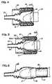
- Figure 2is a sectional view of the catheter in extended condition.
- Figure 3is a sectional view of a catheter embodying the invention in rolled condition.
- Figures 4-6are longitudinal sectional views illustrating steps in the application of the catheter to a patient.
- the numeral 10generally designates a catheter in the form of a thin, unitary sheath of soft elastic material such as, for example, latex or silicone rubber.
- the sheathincludes a generally cylindrical body portion 11, an intermediate portion 12, and a drainage tube portion 13.
- the intermediate portion 12is provided with a rounded taper 14 that merges with.
- the drainage tube portion 13is provided with a rounded taper 14 that merges with.
- Convolutions or annular enlargements 15may be provided in the drainage tube portion at its proximal end, the purpose of such convolutions being to permit greater stretchability, bending, and twisting of the drainage tube portion when the device is in use, and to do so with less chance that kinking or obstruction of the lumen might occur.
- the catheteris conventionally produced by dipping and curing steps in which a mandrel of selected configuration is alternately lowered into and removed from a liquid bath of latex (or other suitable elastomer), with the wall thickness of the intermediate portion 12 and the drainage tube portion 13 being substantially thicker than the wall of cylindrical portion 11.
- the sheathalso includes an annular flap 16 located within the interior of the sheath.
- the flaphas an outer end (determined radially) 16a that merges with the inner surface of the sheath at a point (or line) between cylindrical portion 11 and intermediate portion 12.
- the opposite inner end 16b of the flapdefines an opening 17 slightly smaller than the interior of the cylindrical portion and intermediate portion of the sheath.
- the flapis shown as sloping forwardly or distally but, if desired, the flap may slope in a proximal direction or even extend radially inwardly in a plane normal to the axis of the sheath. Even when the sheath has its flap normally sloping distally, as shown in Figure 2, that flap may tend to reverse its direction when the sheath is tensioned slightly and mounted upon an applicator tube (Figure 1).
- the flap 16should be extremely thin and elastically stretchable. A thickness of about 0.008 inches has been found effective for both the flap and the cylindrical wall, but greater or lesser thicknesses may be provided, if desired.
- the diameter "d" of opening 17should generally fall within the range of 75 to 92% of the inside diameter "D" of the cylindrical body portion 11 when the sheath is in unstretched or untensioned condition.
- the preferred percentage ratiois 78 to 89%, with the optimum falling within the range of about 81 to 87%.
- the length "1" of the flap -- that is, the distance between ends 16a and 16b --should be no greater than 35% of the length "L" of the intermediate portion 12 and, in general, should be within the range of about 6.35 to 16.51 mm (0.25 to 0.65 inches). For adult-sized catheters, the optimum is believed to be about 12.7 mm (0.50 inches), whereas for pediatric catheters a dimension of about 7.62 mm (30 inches) is preferred.
- the d/D ratiois critical because the flap 16 of catheter 10 must be capable of sliding over the glans of the penis (or the foreskin-covered glans for an uncircumcised male) with only limited stretching and, therefore, limited resistance.
- the proper size of a catheter as a wholeis primarily determined by dimension D.
- the cylindrical body portion 11 of the cathetershould have approximately the same diameter (inside), or a slightly smaller diameter, as that of the patient's penis in a flaccid state so that when the sheath is fitted upon the patient, adhesive layer 18 will contact the penile shaft without gaps, wrinkles, or channels that might cause leakage.
- the adhesive layer 18 along the inner surface of cylindrical body portion 11may be of any suitable medical-grade pressure sensitive adhesive.
- a conventional medical-grade acrylic adhesivehas been found effective, but other known adhesives may be used.
- Figure 1depicts catheter 10 supported upon an applicator tube 20.
- the tubeis open-ended and the intermediate portion of the catheter is located within the interior of the tube with the reduced drainage tube portion 13 projecting from one end 20a.
- the cylindrical portion 11 of the catheterextends out of the opening at the opposite end 20b of the tube and is folded backwardly over the outside of the tube.
- a mesh sleeve 21 of nylon, polyethylene, polypropylene, or some other suitable polymeric materialis interposed between the two.
- the adhesive layer 18, on what will become the inner surface of the catheter when the cylindrical section is reverted,is covered by a removable strip of silicone-coated paper tape 22 or other suitable release covering.
- tube 20has a larger inside diameter than the unstretched outside diameter of the sheath, the sheath is stretched slightly about the opening at end 20b and the cylindrical body section 11 is in a moderately tensioned state about the outer surface of the tube. Such stretching may cause the annular flap 16 to protrude outwardly away from the open end 20b of the tube as illustrated in Figure 1. In any case, flap 16 can be easily viewed by the user at the time of application. Such application is commenced by first removing the protective release tape 22 and then urging the open end 20b of the applicator tube over the patient's penis P as depicted in Figure 4. Flap 16 engages the glans (or the foreskin over the glans) and flexes inwardly.
- annular flap 16Effective sealing between annular flap 16 and the penile shaft occurs even though the flap is not highly stretched because the surface of the shaft is generally smooth and of even contour and because backflow, if it should occur, will tend to urge the flap into tighter sealing engagement with the penile shaft. It is to be understood, however, that the short annular flap 16 may be operative, although generally to a lesser extent, if it also engages the rear (proximal) portion of the glans -- that is, if the catheter were applied with penile insertion into intermediate portion 12 no further than as shown in Figure 4.
- catheter 10might instead be rolled in a conventional manner as illustrated in Figure 3.
- some meansare necessary to prevent adhesive 18 from adhering to the outer surface (or what will become the outer surface) of the catheter.
- release meansmight take the form of a release tape or interliner (which in this case should be highly flexible) or of a release coating or release layer (e.g., of silicone rubber) applied to the outer surface of the catheter during manufacture.
- the catheter illustrated in Figure 3is identical to the catheter of Figure 2.
Landscapes
- Health & Medical Sciences (AREA)
- Reproductive Health (AREA)
- Epidemiology (AREA)
- Nursing (AREA)
- Orthopedic Medicine & Surgery (AREA)
- Engineering & Computer Science (AREA)
- Biomedical Technology (AREA)
- Heart & Thoracic Surgery (AREA)
- Vascular Medicine (AREA)
- Life Sciences & Earth Sciences (AREA)
- Animal Behavior & Ethology (AREA)
- General Health & Medical Sciences (AREA)
- Public Health (AREA)
- Veterinary Medicine (AREA)
- Orthopedics, Nursing, And Contraception (AREA)
Description
- Co-owned patents 4,581,026, 4,626,250, and 4,932,948disclose male external catheters intended for use with urinarydrainage systems. Each such catheter is in the form of a sheathhaving a cylindrical body section, an intermediate neck section,and a reduced drainage tube section, with the entire catheterbeing formed of a soft elastic material such as latex orsilicone rubber. In addition, the catheters disclosed in eachof these patents have tubular elongated inner sleeves of softelastic material designed to fit over the glans of a wearer'spenis. Such a sleeve is intended to make sealing contact withthe glans and is maintained in stretched condition over theglans by adhesive means adhering the cylindrical section to thepenile shaft.
- As shown in these patents, the tubular sleeves arerelatively long, so as to cover as much of the glans aspossible, and terminate in small distal openings so that urinemay be discharged into the intermediate neck portions of thesheaths. For sealing effectiveness, it has been consideredimportant to insure that the thin elastic sleeves are stretchedover the glans and are maintained in such stretched conditionwhen the catheters are worn. That requires the caregiver or thepatient (if a catheter is self-applied) to hold the penis inposition as the sleeve is stretched over the glans. Whiledevices have been developed to make the task easier (see, forexample, the applicator of co-owned patent 4,589,874), it isstill necessary for the user to use both hands in theapplication of such a catheter, one for unrolling the sheathover the penis and the other for holding the penis, with thesleeve in stretched condition over the glans, at least at thecommencement of that operation.
- While an adhesively-attached catheter with an inner sleeveoperates effectively if it is applied carefully with the sleevestretched over the glans, instances have occurred where nurses(or other caregivers) have failed to perform such procedures completely, or with sufficient patience and care, because theyare concerned about possible discomfort or injury to thepatient, or are rushing to perform other healthcare duties, orsimply because they find themselves uncomfortable making suchdirect and extended contact with the limp penis of anincontinent patient. If such an external catheter is improperlyor incompletely applied, it may cause considerable patientdiscomfort and produce other serious consequences such asrendering the device ineffective or inoperative and causingleakage of urine when the drainage system is in use.
- Other problems may also arise. If the stretched innersleeve is to cover the glans, it is important that it berelatively long and that its distal opening be small. However,such a device obviously will fail to operate properly if thesmall distal opening of the stretched sleeve is not in registerwith the urethral opening of the patient, so care must be takento assure that proper alignment exists. Also, in fitting such asheath upon a patient, it is important that the sleeve bestretched, but not stretched excessively, because excessivestretching might cause the distal end of the sleeve to bepositionednear the backside of the glans, or even behind the glans,applying a clearly undesirable constrictive force on thepatient.
- Recent developments in catheter-applying techniques involvethe use of catheters that are similar to those described abovebut are not supplied or applied in rolled form and may or maynot have inner sleeves. Reference may be had to co-ownedpatents 5,423,784, 5,336,211, 4,586,974, 4,540,409, and Des.358,882. In each, a catheter is supported by an open-endedapplicator tube with the neck and drainage tube portions of thecatheter located within the tube and the cylindrical portion ofthe catheter reverted or turned backwardly over the outside ofthe tube. Such a system generally allows the user to apply acatheter to a patient without gripping the penis between thefingers, but some gripping may still be necessary if thecatheter has an inner sleeve that should be stretched over theglans during application. In such a case, the ease of application may be decreased rather than increased becauseoperation of the applicator tube in releasing and applying acatheter is itself a two-handed operation, making it difficultfor the user to also hold the penis and stretch the sleeve overthe glans.
- An important aspect of this invention therefore lies in thediscovery that the advantages of sleeve-equipped catheter may berealized without encountering the difficulties indicated aboveif such a sleeve is shortened, its opening is greatly enlarged,and it is positioned so that it may make sealing contact withthe penile shaft rather than the glans. Unlike the innersleeves of the catheters disclosed in the aforementionedpatents, the sleeve of the present catheter must be relativelyshort, taking the form of a narrow annular flap, and its openingmust be relatively large. Specifically, the opening must belarge enough so that the annular flap slides easily over theglans (or the foreskin covering the glans in an uncircumcisedpatient) and will sealingly engage the penile shaft or theproximal portion of the glans (or foreskin) immediately adjacentthe shaft. The flap should be dimensioned so that its openinghas a diameter in the general range of 75 to 92% of the insidediameter of the cylindrical portion of the sheath, with thepreferred range being 78 to 89% and the optimum range beingabout 81 to 87%. The length of the flap depends partly on thesize of the catheter but, in general, the flap should have alength within the range of about 6.35 to 16.15 mm (0.25 to0.65 inches) and should not in any case exceed 35% of thelength of the sheath's intermediate section. A flap length of12.7 mm (0.5 inches) has been found particularly effective foradult-size catheters, whereas 7.62 mm (0.3 inches) has beenfound suitable for a pediatric-size catheter.
- Other features, objects and advantages will becomeapparent from the specification and drawings.
- Figure 1 is a vertical longitudinal sectional view of acatheter embodying the invention in combination with anapplicator tube.
- Figure 2 is a sectional view of the catheter in extendedcondition. Figure 3 is a sectional view of a catheterembodying the invention in rolled condition.
- Figures 4-6 are longitudinal sectional views illustratingsteps in the application of the catheter to a patient.
- Referring to Figure 2 of the drawings, the
numeral 10generally designates a catheter in the form of a thin, unitarysheath of soft elastic material such as, for example, latex orsilicone rubber. The sheath includes a generallycylindricalbody portion 11, anintermediate portion 12, and adrainage tubeportion 13. At its forward or distal end, theintermediateportion 12 is provided with arounded taper 14 that merges with.thedrainage tube portion 13. Convolutions orannularenlargements 15 may be provided in the drainage tube portion atits proximal end, the purpose of such convolutions being topermit greater stretchability, bending, and twisting of thedrainage tube portion when the device is in use, and to do sowith less chance that kinking or obstruction of the lumen mightoccur. The catheter is conventionally produced by dipping andcuring steps in which a mandrel of selected configuration isalternately lowered into and removed from a liquid bath of latex(or other suitable elastomer), with the wall thickness of theintermediate portion 12 and thedrainage tube portion 13 beingsubstantially thicker than the wall ofcylindrical portion 11. - The sheath also includes an
annular flap 16 located withinthe interior of the sheath. The flap has an outer end(determined radially) 16a that merges with the inner surface ofthe sheath at a point (or line) betweencylindrical portion 11andintermediate portion 12. The oppositeinner end 16b of theflap defines anopening 17 slightly smaller than the interior ofthe cylindrical portion and intermediate portion of the sheath.In Figure 2, the flap is shown as sloping forwardly or distallybut, if desired, the flap may slope in a proximal direction oreven extend radially inwardly in a plane normal to the axis ofthe sheath. Even when the sheath has its flap normally slopingdistally, as shown in Figure 2, that flap may tend to reverse its direction when the sheath is tensioned slightly and mountedupon an applicator tube (Figure 1). - Like the
cylindrical portion 11, theflap 16 should beextremely thin and elastically stretchable. A thickness ofabout 0.008 inches has been found effective for both the flapand the cylindrical wall, but greater or lesser thicknesses maybe provided, if desired. - There is a critical size relationship between the openingof
flap 16 and the inside diameter of thecylindrical portion 11if effective sealing and safe operation of the catheter are tobe achieved. The diameter "d" ofopening 17 should generallyfall within the range of 75 to 92% of the inside diameter "D" ofthecylindrical body portion 11 when the sheath is inunstretched or untensioned condition. The preferred percentageratio is 78 to 89%, with the optimum falling within the range ofabout 81 to 87%. The length "1" of the flap -- that is, thedistance betweenends intermediate portion 12 and, ingeneral, should be within the range of about 6.35 to 16.51 mm(0.25 to 0.65 inches). For adult-sized catheters, the optimumis believed to be about 12.7 mm (0.50 inches), whereas forpediatric catheters a dimension of about 7.62 mm (30 inches)is preferred. - The d/D ratio is critical because the
flap 16 ofcatheter 10 must be capable of sliding over the glans of the penis (orthe foreskin-covered glans for an uncircumcised male) with onlylimited stretching and, therefore, limited resistance. For anygiven patient the proper size of a catheter as a whole isprimarily determined by dimension D. Ideally, thecylindricalbody portion 11 of the catheter should have approximately thesame diameter (inside), or a slightly smaller diameter, as thatof the patient's penis in a flaccid state so that when thesheath is fitted upon the patient,adhesive layer 18 willcontact the penile shaft without gaps, wrinkles, or channelsthat might cause leakage. Therefore, while catheters of thetype depicted in Figure 2 would be available in severaldifferent sizes, once such a catheter of proper size is selectedfor a given patient, based on dimension D, theflap opening 17will also be of the proper size if the catheter embodies d/D ratios given above. - The
adhesive layer 18 along the inner surface ofcylindrical body portion 11 may be of any suitable medical-gradepressure sensitive adhesive. A conventional medical-gradeacrylic adhesive has been found effective, but other knownadhesives may be used. - Figure 1 depicts
catheter 10 supported upon anapplicatortube 20. The tube is open-ended and the intermediate portion ofthe catheter is located within the interior of the tube with thereduceddrainage tube portion 13 projecting from oneend 20a.Thecylindrical portion 11 of the catheter extends out of theopening at the opposite end 20b of the tube and is foldedbackwardly over the outside of the tube. To reduce frictionbetween the catheter and the surfaces along the outside and end20b of thetube 20, a mesh sleeve 21 of nylon, polyethylene,polypropylene, or some other suitable polymeric material isinterposed between the two. Theadhesive layer 18, on what willbecome the inner surface of the catheter when the cylindricalsection is reverted, is covered by a removable strip ofsilicone-coatedpaper tape 22 or other suitable releasecovering. - Since
tube 20 has a larger inside diameter than theunstretched outside diameter of the sheath, the sheath isstretched slightly about the opening at end 20b and thecylindrical body section 11 is in a moderately tensioned stateabout the outer surface of the tube. Such stretching may causetheannular flap 16 to protrude outwardly away from the open end20b of the tube as illustrated in Figure 1. In any case,flap 16 can be easily viewed by the user at the time of application.Such application is commenced by first removing theprotectiverelease tape 22 and then urging the open end 20b of theapplicator tube over the patient's penis P as depicted in Figure4.Flap 16 engages the glans (or the foreskin over the glans)and flexes inwardly. Continued advancement of thetube 20brings theflap 16 to a position about the penile shaft directlybehind the glans (Figure 5). Thereafter, the user grips theexposed portion of the applicator tube nearend 20a and pullsthedrainage tube portion 13 of the catheter in a distal direction (away from the patient) while simultaneously urgingtheapplicator tube 20 in a proximal direction (towards thepatient) to cause thecylindrical body portion 11 to slide offof the applicator tube and onto the penile shaft. Theapplicator tube 20 and mesh sleeve 21 are then withdrawn,leaving the catheter in place upon the patient as illustrated inFigure 6. - Effective sealing between
annular flap 16 and the penileshaft occurs even though the flap is not highly stretchedbecause the surface of the shaft is generally smooth and of evencontour and because backflow, if it should occur, will tend tourge the flap into tighter sealing engagement with the penileshaft. It is to be understood, however, that the shortannularflap 16 may be operative, although generally to a lesser extent,if it also engages the rear (proximal) portion of the glans --that is, if the catheter were applied with penile insertion intointermediate portion 12 no further than as shown in Figure 4. - While the use of an
applicator tube 20 is preferred,catheter 10 might instead be rolled in a conventional manner asillustrated in Figure 3. In such a case, some means arenecessary to prevent adhesive 18 from adhering to the outersurface (or what will become the outer surface) of the catheter.Such release means might take the form of a release tape orinterliner (which in this case should be highly flexible) or ofa release coating or release layer (e.g., of silicone rubber)applied to the outer surface of the catheter during manufacture.In all other respects, the catheter illustrated in Figure 3 isidentical to the catheter of Figure 2. - While in the foregoing, we have disclosed embodiments ofthe invention in considerable detail for purposes ofillustration, it will be understood by those skilled in the artthat many of these details may be varied without departing fromthe scope of the invention.
Claims (4)
- The combination of a male external catheter andapplicator therefor; said catheter comprising a tubular sheath(10) formed of soft elastic material having a thin-walledcylindrical portion (11) for extending over the shaft of apatient's penis and having an adhesive coating (18) along aportion of its inside surface, a reduced drainage tube portion(13), and an intermediate portion (12) adapted to extend overand about a patient's glans and merging with both saiddrainage tube portion (13) and said cylindrical portion (11);said sheath also including a thin, elastic, inwardly-extendingannular flap (16) having an outer end (16a) merging with saidsheath between said cylindrical portion (11) and saidintermediate portion (12) and having an inner end (16b)defining a generally circular opening (17); said applicatorcomprising a rigid and open-ended applicator tube (20); saidintermediate portion (12) of said sheath (10) being locatedwithin said applicator tube (20) and said drainage tubeportion (13) extending through and beyond the opening (20a) atone end of said applicator tube; said cylindrical portion (11)of said sheath extending out of the opening at the oppositeend (20b) of said applicator tube (20) and extending along theouter surface of said applicator tube; and anti-friction means(21) interposed between the outer surface of said applicatortube and said sheath;characterized bysaid opening (17) at said inner end (16b) of said flap(16) having a diameter of 75% to 92% of the inside diameter ofsaid cylindrical portion (11), and a length within the rangeof 6.35 mm to 16.51 mm, when said flap (16) and cylindricalportion (11) are unstretched.
- The combination of Claim 1 in which said annular flap(16) has an opening (17) of about 78% to 89% of the insidediameter of said cylindrical portion (11).
- The combination of Claim 1 in which said flap (16) has anopening (17) diameter of about 81% to 87% of the insidediameter of said cylindrical portion (11).
- The combination of Claims 1, 2 or 3 in which said annularflap (16) has a length no greater than 35% of the length ofsaid intermediate portion (12).
Applications Claiming Priority (2)
| Application Number | Priority Date | Filing Date | Title |
|---|---|---|---|
| US542180 | 1995-10-12 | ||
| US08/542,180US6007526A (en) | 1995-10-12 | 1995-10-12 | Male external catheter with short annular sealing flap |
Publications (2)
| Publication Number | Publication Date |
|---|---|
| EP0768069A1 EP0768069A1 (en) | 1997-04-16 |
| EP0768069B1true EP0768069B1 (en) | 2002-02-20 |
Family
ID=24162682
Family Applications (1)
| Application Number | Title | Priority Date | Filing Date |
|---|---|---|---|
| EP96306652AExpired - LifetimeEP0768069B1 (en) | 1995-10-12 | 1996-09-13 | Male external catheter with short annular sealing flap |
Country Status (5)
| Country | Link |
|---|---|
| US (1) | US6007526A (en) |
| EP (1) | EP0768069B1 (en) |
| CA (1) | CA2187808A1 (en) |
| DE (1) | DE69619326T2 (en) |
| DK (1) | DK0768069T3 (en) |
Families Citing this family (51)
| Publication number | Priority date | Publication date | Assignee | Title |
|---|---|---|---|---|
| US7186245B1 (en)* | 1999-06-29 | 2007-03-06 | Cheng Gordon C | Personal urine management system for human males |
| DE29917146U1 (en)* | 1999-09-29 | 2000-04-27 | ANDROMEDA medizinische Systeme GmbH, 82024 Taufkirchen | Urinal condom |
| US6635037B1 (en) | 2000-12-29 | 2003-10-21 | Patricia A. Bennett | Male urinary incontinence device |
| US6805690B2 (en)* | 2002-05-10 | 2004-10-19 | Mentor Corporation | Male external catheters |
| US6732384B2 (en)* | 2002-05-22 | 2004-05-11 | Barbara Scott | Pump augmented urine collector |
| US7032251B2 (en)* | 2002-12-10 | 2006-04-25 | Kimberly-Clark Worldwide, Inc. | Crosslinking agent for coated elastomeric articles |
| CA2577797A1 (en)* | 2004-08-30 | 2006-03-09 | Coloplast A/S | An external urinary catheter |
| AU2005281707B2 (en)* | 2004-09-06 | 2010-12-09 | Coloplast A/S | Silicone urisheath with integrated adhesive |
| US8864730B2 (en) | 2005-04-12 | 2014-10-21 | Rochester Medical Corporation | Silicone rubber male external catheter with absorbent and adhesive |
| US8491552B2 (en)* | 2006-09-25 | 2013-07-23 | Adapta Medical, Inc. | External catheter with antiseptic agent |
| US20080287895A1 (en)* | 2007-05-17 | 2008-11-20 | Francis Ouellet | Method and device for applying a condom |
| GB0813459D0 (en)* | 2008-07-23 | 2008-08-27 | British American Tobacco Co | Ventilating sheath for smoking article |
| AU2010241535A1 (en)* | 2009-12-17 | 2011-07-07 | Vollrath, Klaus Michael Andreas Mr | Device for Facilitating Semen Collection |
| MX382876B (en) | 2010-07-30 | 2025-03-13 | Alcon Inc | SILICONE HYDROGEL LENSES WITH WATER-RICH SURFACES. |
| US9707375B2 (en) | 2011-03-14 | 2017-07-18 | Rochester Medical Corporation, a subsidiary of C. R. Bard, Inc. | Catheter grip and method |
| EP2766750B1 (en) | 2011-10-12 | 2016-02-03 | Novartis AG | Method for making uv-absorbing ophthalmic lenses by coating |
| US9872969B2 (en) | 2012-11-20 | 2018-01-23 | Rochester Medical Corporation, a subsidiary of C.R. Bard, Inc. | Catheter in bag without additional packaging |
| US10092728B2 (en) | 2012-11-20 | 2018-10-09 | Rochester Medical Corporation, a subsidiary of C.R. Bard, Inc. | Sheath for securing urinary catheter |
| US10338408B2 (en) | 2012-12-17 | 2019-07-02 | Novartis Ag | Method for making improved UV-absorbing ophthalmic lenses |
| MY180543A (en) | 2013-12-17 | 2020-12-01 | Novartis Ag | A silicone hydrogel lens with a crosslinked hydrophilic coating |
| US11376152B2 (en) | 2014-03-19 | 2022-07-05 | Purewick Corporation | Apparatus and methods for receiving discharged urine |
| CN103976812A (en)* | 2014-05-12 | 2014-08-13 | 宁波新海电气股份有限公司 | Urine receptor for male and urine device |
| WO2016032926A1 (en) | 2014-08-26 | 2016-03-03 | Novartis Ag | Method for applying stable coating on silicone hydrogel contact lenses |
| WO2016033234A1 (en) | 2014-08-26 | 2016-03-03 | C.R. Bard, Inc | Urinary catheter |
| US20160129221A1 (en)* | 2014-11-07 | 2016-05-12 | Boston Scientific Scimed, Inc. | Medical device having an atraumatic distal tip |
| MY184638A (en) | 2015-12-15 | 2021-04-13 | Alcon Inc | Method for applying stable coating on silicone hydrogel contact lenses |
| US10675175B2 (en)* | 2016-06-13 | 2020-06-09 | Katelyn P. Holt | Male catheter |
| JP2020510464A (en) | 2017-01-31 | 2020-04-09 | ピュアウィック コーポレイション | Apparatus and method for receiving excreted urine |
| US10709873B1 (en)* | 2017-02-04 | 2020-07-14 | Jeanie L. Green | Device for holding a catheter in place |
| AU2018337731C1 (en) | 2017-09-19 | 2024-02-01 | C.R. Bard, Inc. | Urinary catheter bridging device, systems and methods thereof |
| US11259954B2 (en)* | 2017-09-28 | 2022-03-01 | Sabry Gabriel | Condom catheters and methods of making and using the same |
| US11029446B2 (en) | 2017-12-13 | 2021-06-08 | Alcon Inc. | Method for producing MPS-compatible water gradient contact lenses |
| WO2019212952A1 (en) | 2018-05-01 | 2019-11-07 | Purewick Corporation | Fluid collection devices, related systems, and related methods |
| KR102492111B1 (en) | 2018-05-01 | 2023-01-27 | 퓨어윅 코포레이션 | Fluid Collection Devices and Methods of Using The Same |
| KR102513810B1 (en) | 2018-05-01 | 2023-03-24 | 퓨어윅 코포레이션 | Fluid collection devices, systems and methods |
| WO2020256865A1 (en) | 2019-06-21 | 2020-12-24 | Purewick Corporation | Fluid collection devices including a base securement area, and related systems and methods |
| US12329364B2 (en) | 2019-07-19 | 2025-06-17 | Purewick Corporation | Fluid collection devices including at least one shape memory material |
| DE102019131976A1 (en)* | 2019-11-26 | 2021-05-27 | Chin-Hung Chiu | CONSTRUCTION OF A WATER DRAINING DEVICE |
| US12350190B2 (en) | 2020-01-03 | 2025-07-08 | Purewick Corporation | Urine collection devices having a relatively wide portion and an elongated portion and related methods |
| US20220047410A1 (en) | 2020-08-11 | 2022-02-17 | Purewick Corporation | Fluid collection assemblies defining waist and leg openings |
| US20220062027A1 (en)* | 2020-09-02 | 2022-03-03 | Purewick Corporation | Systems and methods including a male fluid collection device and a securement element |
| US12208031B2 (en) | 2020-10-21 | 2025-01-28 | Purewick Corporation | Adapters for fluid collection devices |
| US12257174B2 (en) | 2020-10-21 | 2025-03-25 | Purewick Corporation | Fluid collection assemblies including at least one of a protrusion or at least one expandable material |
| US12070432B2 (en) | 2020-11-11 | 2024-08-27 | Purewick Corporation | Urine collection system including a flow meter and related methods |
| US12245967B2 (en) | 2020-11-18 | 2025-03-11 | Purewick Corporation | Fluid collection assemblies including an adjustable spine |
| US12268627B2 (en) | 2021-01-06 | 2025-04-08 | Purewick Corporation | Fluid collection assemblies including at least one securement body |
| CA3162613A1 (en) | 2021-01-19 | 2022-07-19 | Purewick Corporation | Variable fit fluid collection devices, systems, and methods |
| EP4274524B1 (en) | 2021-02-26 | 2024-08-28 | Purewick Corporation | A male fluid collection device configured as a male urine collection device |
| US12233003B2 (en) | 2021-04-29 | 2025-02-25 | Purewick Corporation | Fluid collection assemblies including at least one length adjusting feature |
| US12251333B2 (en) | 2021-05-21 | 2025-03-18 | Purewick Corporation | Fluid collection assemblies including at least one inflation device and methods and systems of using the same |
| US12324767B2 (en) | 2021-05-24 | 2025-06-10 | Purewick Corporation | Fluid collection assembly including a customizable external support and related methods |
Family Cites Families (18)
| Publication number | Priority date | Publication date | Assignee | Title |
|---|---|---|---|---|
| US33206A (en)* | 1861-09-03 | Improvement in the arrangement of apparatus for the manufacture of vinegar by the | ||
| US3577990A (en)* | 1968-03-13 | 1971-05-11 | Henry E Borgerson | Urinary appliance |
| US3526227A (en)* | 1970-01-02 | 1970-09-01 | Louis Appelbaum | Urinal bag |
| SE355488B (en)* | 1970-02-24 | 1973-04-30 | Stille Werner Ab | |
| US4626250A (en)* | 1981-06-05 | 1986-12-02 | Hollister Incorporated | Male urinary collection system and external catheter therefor |
| US4581026A (en)* | 1981-06-05 | 1986-04-08 | Hollister Incorporated | Male urinary collection system and external catheter therefor |
| IE52880B1 (en)* | 1981-06-05 | 1988-03-30 | Hollister Inc | A male urinary collection system and axternal catheter therefor |
| USRE33206E (en) | 1981-10-02 | 1990-05-01 | Mentor Corporation | Male condom catheter having adhesive on rolled portion |
| US4586974A (en)* | 1983-07-05 | 1986-05-06 | Hollister Incorporated | Process of forming an external male catheter and applicator |
| US4540409A (en)* | 1983-07-05 | 1985-09-10 | Hollister Incorporated | External male catheter and applicator |
| US4589874A (en)* | 1985-03-21 | 1986-05-20 | Hollister Incorporated | External male catheter and applicator collar therefor |
| GB8526531D0 (en)* | 1985-10-28 | 1985-12-04 | Negretti Aviat Ltd | Urination facility |
| US4759753A (en)* | 1986-12-12 | 1988-07-26 | Hollister Incorporated | External male urinary catheter |
| US4932948A (en)* | 1988-03-28 | 1990-06-12 | Hollister Incorporated | Male external catheter and antimicrobial insert therefor |
| US5336211A (en)* | 1992-10-22 | 1994-08-09 | Hollister Incorporated | External male catheter, applicator and method of use |
| USD358882S (en) | 1993-09-01 | 1995-05-30 | Hollister Incorporated | Combined male urinary catheter and applicator tube |
| US5423784A (en)* | 1994-01-11 | 1995-06-13 | Hollister Incorporated | Extended male catheter applicator and methods of use |
| US5424784A (en)* | 1994-09-06 | 1995-06-13 | Raytheon Company | Method and apparatus for cross fading between combed and simple filtered outputs |
- 1995
- 1995-10-12USUS08/542,180patent/US6007526A/ennot_activeExpired - Lifetime
- 1996
- 1996-09-13DEDE69619326Tpatent/DE69619326T2/ennot_activeExpired - Fee Related
- 1996-09-13DKDK96306652Tpatent/DK0768069T3/enactive
- 1996-09-13EPEP96306652Apatent/EP0768069B1/ennot_activeExpired - Lifetime
- 1996-10-11CACA002187808Apatent/CA2187808A1/ennot_activeAbandoned
Also Published As
| Publication number | Publication date |
|---|---|
| CA2187808A1 (en) | 1997-04-13 |
| DE69619326T2 (en) | 2002-07-25 |
| DK0768069T3 (en) | 2002-06-03 |
| EP0768069A1 (en) | 1997-04-16 |
| DE69619326D1 (en) | 2002-03-28 |
| US6007526A (en) | 1999-12-28 |
Similar Documents
| Publication | Publication Date | Title |
|---|---|---|
| EP0768069B1 (en) | Male external catheter with short annular sealing flap | |
| US5336211A (en) | External male catheter, applicator and method of use | |
| US4540409A (en) | External male catheter and applicator | |
| US5423784A (en) | Extended male catheter applicator and methods of use | |
| CA1263830A (en) | External male catheter and applicator collar therefor | |
| US5752944A (en) | Male incontinence device | |
| US4759753A (en) | External male urinary catheter | |
| US5078707A (en) | External urine collection device | |
| US4378018A (en) | Male urinary drainage device | |
| US4840187A (en) | Sheath applicator | |
| US6068618A (en) | External male catheter | |
| EP0666070B1 (en) | Male incontinence device | |
| JPS6290172A (en) | Urine sampling catheter | |
| US4586974A (en) | Process of forming an external male catheter and applicator | |
| EP0284224B1 (en) | External male incontinence device | |
| JP2018501058A (en) | Urethral catheter assembly and method | |
| GB2252247A (en) | Applying male urinary incontinence devices | |
| US5275587A (en) | Applicator for external catheter and method of using same | |
| AU665095B2 (en) | External male catheter and applicator | |
| GB2279256A (en) | External male catheter and applicator | |
| JPH08506257A (en) | Urine tools and condoms | |
| DK9300316U3 (en) | Combined catheter and applicator | |
| JPH079317U (en) | External catheter and applicator combination for men | |
| JPH03123547A (en) | Urine discharge apparatus for male |
Legal Events
| Date | Code | Title | Description |
|---|---|---|---|
| PUAI | Public reference made under article 153(3) epc to a published international application that has entered the european phase | Free format text:ORIGINAL CODE: 0009012 | |
| AK | Designated contracting states | Kind code of ref document:A1 Designated state(s):DE DK FR GB | |
| 17P | Request for examination filed | Effective date:19970625 | |
| 17Q | First examination report despatched | Effective date:20000718 | |
| GRAG | Despatch of communication of intention to grant | Free format text:ORIGINAL CODE: EPIDOS AGRA | |
| GRAG | Despatch of communication of intention to grant | Free format text:ORIGINAL CODE: EPIDOS AGRA | |
| GRAH | Despatch of communication of intention to grant a patent | Free format text:ORIGINAL CODE: EPIDOS IGRA | |
| GRAH | Despatch of communication of intention to grant a patent | Free format text:ORIGINAL CODE: EPIDOS IGRA | |
| REG | Reference to a national code | Ref country code:GB Ref legal event code:IF02 | |
| GRAA | (expected) grant | Free format text:ORIGINAL CODE: 0009210 | |
| AK | Designated contracting states | Kind code of ref document:B1 Designated state(s):DE DK FR GB | |
| REF | Corresponds to: | Ref document number:69619326 Country of ref document:DE Date of ref document:20020328 | |
| REG | Reference to a national code | Ref country code:DK Ref legal event code:T3 | |
| ET | Fr: translation filed | ||
| PLBE | No opposition filed within time limit | Free format text:ORIGINAL CODE: 0009261 | |
| STAA | Information on the status of an ep patent application or granted ep patent | Free format text:STATUS: NO OPPOSITION FILED WITHIN TIME LIMIT | |
| 26N | No opposition filed | Effective date:20021121 | |
| PGFP | Annual fee paid to national office [announced via postgrant information from national office to epo] | Ref country code:DK Payment date:20040916 Year of fee payment:9 | |
| PGFP | Annual fee paid to national office [announced via postgrant information from national office to epo] | Ref country code:FR Payment date:20050823 Year of fee payment:10 | |
| PGFP | Annual fee paid to national office [announced via postgrant information from national office to epo] | Ref country code:GB Payment date:20050907 Year of fee payment:10 | |
| PGFP | Annual fee paid to national office [announced via postgrant information from national office to epo] | Ref country code:DE Payment date:20050909 Year of fee payment:10 | |
| PG25 | Lapsed in a contracting state [announced via postgrant information from national office to epo] | Ref country code:DK Free format text:LAPSE BECAUSE OF NON-PAYMENT OF DUE FEES Effective date:20050930 | |
| REG | Reference to a national code | Ref country code:DK Ref legal event code:EBP | |
| PG25 | Lapsed in a contracting state [announced via postgrant information from national office to epo] | Ref country code:DE Free format text:LAPSE BECAUSE OF NON-PAYMENT OF DUE FEES Effective date:20070403 | |
| GBPC | Gb: european patent ceased through non-payment of renewal fee | Effective date:20060913 | |
| REG | Reference to a national code | Ref country code:FR Ref legal event code:ST Effective date:20070531 | |
| PG25 | Lapsed in a contracting state [announced via postgrant information from national office to epo] | Ref country code:GB Free format text:LAPSE BECAUSE OF NON-PAYMENT OF DUE FEES Effective date:20060913 | |
| PG25 | Lapsed in a contracting state [announced via postgrant information from national office to epo] | Ref country code:FR Free format text:LAPSE BECAUSE OF NON-PAYMENT OF DUE FEES Effective date:20061002 |