EP0766166B1 - Casing for computing equipment - Google Patents
Casing for computing equipmentDownload PDFInfo
- Publication number
- EP0766166B1 EP0766166B1EP96306974AEP96306974AEP0766166B1EP 0766166 B1EP0766166 B1EP 0766166B1EP 96306974 AEP96306974 AEP 96306974AEP 96306974 AEP96306974 AEP 96306974AEP 0766166 B1EP0766166 B1EP 0766166B1
- Authority
- EP
- European Patent Office
- Prior art keywords
- leaf
- base
- casing
- casing according
- leaves
- Prior art date
- Legal status (The legal status is an assumption and is not a legal conclusion. Google has not performed a legal analysis and makes no representation as to the accuracy of the status listed.)
- Expired - Lifetime
Links
Images

Classifications
- G—PHYSICS
- G06—COMPUTING OR CALCULATING; COUNTING
- G06F—ELECTRIC DIGITAL DATA PROCESSING
- G06F1/00—Details not covered by groups G06F3/00 - G06F13/00 and G06F21/00
- G06F1/16—Constructional details or arrangements
- G06F1/1613—Constructional details or arrangements for portable computers
- G06F1/1615—Constructional details or arrangements for portable computers with several enclosures having relative motions, each enclosure supporting at least one I/O or computing function
- G06F1/1616—Constructional details or arrangements for portable computers with several enclosures having relative motions, each enclosure supporting at least one I/O or computing function with folding flat displays, e.g. laptop computers or notebooks having a clamshell configuration, with body parts pivoting to an open position around an axis parallel to the plane they define in closed position
- G—PHYSICS
- G06—COMPUTING OR CALCULATING; COUNTING
- G06F—ELECTRIC DIGITAL DATA PROCESSING
- G06F1/00—Details not covered by groups G06F3/00 - G06F13/00 and G06F21/00
- G06F1/16—Constructional details or arrangements
- G06F1/1613—Constructional details or arrangements for portable computers
- G06F1/1615—Constructional details or arrangements for portable computers with several enclosures having relative motions, each enclosure supporting at least one I/O or computing function
- G06F1/1624—Constructional details or arrangements for portable computers with several enclosures having relative motions, each enclosure supporting at least one I/O or computing function with sliding enclosures, e.g. sliding keyboard or display
- G—PHYSICS
- G06—COMPUTING OR CALCULATING; COUNTING
- G06F—ELECTRIC DIGITAL DATA PROCESSING
- G06F1/00—Details not covered by groups G06F3/00 - G06F13/00 and G06F21/00
- G06F1/16—Constructional details or arrangements
- G06F1/1613—Constructional details or arrangements for portable computers
- G06F1/1633—Constructional details or arrangements of portable computers not specific to the type of enclosures covered by groups G06F1/1615 - G06F1/1626
- G06F1/1675—Miscellaneous details related to the relative movement between the different enclosures or enclosure parts
- G06F1/1679—Miscellaneous details related to the relative movement between the different enclosures or enclosure parts for locking or maintaining the movable parts of the enclosure in a fixed position, e.g. latching mechanism at the edge of the display in a laptop or for the screen protective cover of a PDA
- Y—GENERAL TAGGING OF NEW TECHNOLOGICAL DEVELOPMENTS; GENERAL TAGGING OF CROSS-SECTIONAL TECHNOLOGIES SPANNING OVER SEVERAL SECTIONS OF THE IPC; TECHNICAL SUBJECTS COVERED BY FORMER USPC CROSS-REFERENCE ART COLLECTIONS [XRACs] AND DIGESTS
- Y10—TECHNICAL SUBJECTS COVERED BY FORMER USPC
- Y10T—TECHNICAL SUBJECTS COVERED BY FORMER US CLASSIFICATION
- Y10T403/00—Joints and connections
- Y10T403/32—Articulated members
- Y10T403/32008—Plural distinct articulation axes
- Y10T403/32091—Plural translating connections
Definitions
- the inventionrelates to a casing for computing equipment, for example palmtop and notebook style computers.
- Conventional palmtop and notebook computerssuch as the Psion Series 3a, have a two leaf casing, a key pad being mounted in one leaf and a display in the other. In an open position, the leaf holding the key pad rests on a surface and the leaf holding the display is in an upright orientation. It would be useful if a touch screen facility could be provided on the display. However, the problem with incorporating such a touch screen is that when the user wishes to touch the screen, he will need to support the casing to prevent it from tipping over, which is clearly undesirable.
- a casing for computing equipmentcomprises first and second leaves for mounting the computer equipment, the leaves being hinged together so as to be movable between a folded position in which the first leaf overlies the second, and an open position; and a base to which the leaves are movably secured so as to allow the second leaf to slide relative to the base whereby in the open position of the leaves part of the base extends under the first leaf so as to provide a support to resist tipping movement when pressure is applied to the first leaf.
- the second leafcould be mounted via slide members directly to the base but preferably the leaves are secured to the base by a hinge mechanism extending between the first leaf and the base whereby pivotal movement of the first leaf relative to the second leaf causes sliding movement of the second leaf relative to the base. This is particularly convenient since a single pivoting movement of the first leaf relative to the second leaf will also cause the sliding movement.
- the hinge mechanismcould be provided in a variety of ways but typically will comprise a pair of laterally spaced arms each coupled at one end to the first leaf and pivoted to the base at the other end.
- the casingmay be provided with a locking mechanism for locking the leaves in the closed and open positions respectively.
- the casingfurther comprises an urging mechanism for urging the leaves towards at least one, and preferably both, of the folded and open positions.
- the urging mechanismcould be in the form of an over centre mechanism such as a torsion spring.
- the urging mechanismforms part of the hinge mechanism although it is not essential and the two could be provided as separate components.
- the inventionis particularly suited for use with a palmtop or notebook computer and in that case, preferably the base has similar dimensions in plan to the second leaf so that in the closed position the second leaf substantially covers the base. This provides a very neat and compact construction enabling the casing to be carried in a pocket or the like.
- the first leaf of the casingpreferably includes a display while an input device such as a key pad is mounted in the second leaf.
- the displayincludes a touch sensitive screen
- the baseprovides support to enable pressure to be applied to the screen without tipping the casing over.
- the computer shown in the drawingscomprises a casing having a first, upper leaf 1 which is hinged at 2 to a second, lower leaf 3.
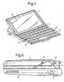
- the upper leaf 1supports a touch screen 4 while the lower leaf supports a keyboard 5.
- a microprocessor(not shown) is mounted within the lower leaf 3 and is attached to the keyboard 5 and the touch screen 4.
- the lower leaf 3is slidably mounted on a base 6.
- the rear section of the base 6incorporates a battery housing 7 ( Figures 3-5) for supplying power to the microprocessor.
- the upper leaf 1is connected to the base 6 via a torsion spring 8 having a pair of laterally spaced arms 9,10 at its ends, each of which terminates in a laterally outwardly extending hook 11. Each hook 11 is received in a respective aperture 12 in the side of the casing 1.
- a central section 13 of the torsion spring 8is formed into a U-shape and is clamped onto a mounting 14, fixed to the base 6, by clamp members 15.
- the torsion spring 8is formed to as to define an over centre mechanism urging the leaf 1 either into the closed position shown in Figure 3 or the fully open position shown in Figure 5.
- the leaf 3 carrying the keyboard 5is slidably mounted to the base 6 due to engagement between a chassis member 16 forming part of the base 6 and a base member 17 of the keyboard 5.
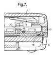
- the interlocking engagement between the chassis member 16 and the base member 17can be seen more clearly in Figure 7.
- the chassis member 16is secured to a support plate 18 while the base member 17 of the keyboard 5 rests slidably on the chassis member 16.
- the base member 17has a number of upstanding bosses 19 defining respective bores 20 some of which are indicated in Figure 6 and Figure 7.
- Each boss 19supports a respective key 21 of the keyboard 15 which has, on its underside, a depending spigot (not shown) which is received within the cruciform shaped bore 20.
- the construction of the keyboardcan have a variety of forms but in the preferred arrangement is in accordance with the key assembly described and claimed in our co-pending patent application of even date entitled "Key Assembly" and claiming priority from British Patent Application No. 9519557.4.
- the usercan press, either with his finger or a suitable tool, the touch screen 4 and the reaction force to this pressure will be provided by the part of the base 6 lying behind the leaf 1 since the downward force is transmitted through the arms 9,10 of the torsion spring 8 to the rest of the torsion spring and hence to the base 6. Furthermore, the centre of gravity of the leaf 1 overlies the base 6 thus also reducing the risk of tipping movement. Similarly, pressure applied to keys on the keyboard 5 will also not cause significant pivoting movement of the computer.
- an L-shaped lug 25is provided on a front end of the leaf 3 which can act as a stabilising foot in the open position as shown in Figure 5 and which, in the closed position, locks into an aperture (not shown) provided in the front edge of the base 6 to prevent inadvertent opening of the leaf 1.
Landscapes
- Engineering & Computer Science (AREA)
- Theoretical Computer Science (AREA)
- Computer Hardware Design (AREA)
- Physics & Mathematics (AREA)
- Human Computer Interaction (AREA)
- General Engineering & Computer Science (AREA)
- General Physics & Mathematics (AREA)
- Mathematical Physics (AREA)
- Casings For Electric Apparatus (AREA)
- Position Input By Displaying (AREA)
- Calculators And Similar Devices (AREA)
- Input From Keyboards Or The Like (AREA)
Description
- The invention relates to a casing for computingequipment, for example palmtop and notebook stylecomputers.
- Conventional palmtop and notebook computers, such asthe Psion Series 3a, have a two leaf casing, a key padbeing mounted in one leaf and a display in the other. Inan open position, the leaf holding the key pad rests on asurface and the leaf holding the display is in an uprightorientation. It would be useful if a touch screen facilitycould be provided on the display. However, the problemwith incorporating such a touch screen is that when theuser wishes to touch the screen, he will need to supportthe casing to prevent it from tipping over, which isclearly undesirable.
- One solution would be to allow the leaves to hingeinto a fully horizontal orientation but this then makes itdifficult to gain access to the screen without interferingwith the key pad.
- In accordance with the present invention, a casing forcomputing equipment comprises first and second leaves formounting the computer equipment, the leaves being hingedtogether so as to be movable between a folded position inwhich the first leaf overlies the second, and an openposition; and a base to which the leaves are movablysecured so as to allow the second leaf to slide relative tothe base whereby in the open position of the leaves part ofthe base extends under the first leaf so as to provide asupport to resist tipping movement when pressure is appliedto the first leaf.
- We have devised a self-contained casing whichautomatically provides a support to resist tipping movementof the casing when pressure is applied to the first leaf(which would typically include a display). This allows thefirst leaf to be positioned at an obtuse angle relative tothe second leaf when in the open position so as to beconveniently oriented for use.
- The second leaf could be mounted via slide membersdirectly to the base but preferably the leaves are securedto the base by a hinge mechanism extending between thefirst leaf and the base whereby pivotal movement of thefirst leaf relative to the second leaf causes slidingmovement of the second leaf relative to the base. This isparticularly convenient since a single pivoting movement ofthe first leaf relative to the second leaf will also causethe sliding movement.
- The hinge mechanism could be provided in a variety ofways but typically will comprise a pair of laterally spacedarms each coupled at one end to the first leaf and pivotedto the base at the other end.
- In some cases, the casing may be provided with alocking mechanism for locking the leaves in the closed andopen positions respectively. Conveniently, however, thecasing further comprises an urging mechanism for urging theleaves towards at least one, and preferably both, of thefolded and open positions. The urging mechanism could bein the form of an over centre mechanism such as a torsionspring.
- Conveniently, the urging mechanism forms part of thehinge mechanism although it is not essential and the twocould be provided as separate components.
- The invention is particularly suited for use with apalmtop or notebook computer and in that case, preferablythe base has similar dimensions in plan to the second leafso that in the closed position the second leafsubstantially covers the base. This provides a very neatand compact construction enabling the casing to be carriedin a pocket or the like.
- As mentioned above, in use, the first leaf of thecasing preferably includes a display while an input devicesuch as a key pad is mounted in the second leaf. Where thedisplay includes a touch sensitive screen, the baseprovides support to enable pressure to be applied to thescreen without tipping the casing over.
- An example of a portable, palmtop computer mounted ina casing according to the invention will now be describedwith reference to the accompanying drawings, in which:-
- Figure 1 is a perspective view from above showing thecomputer in its open position;
- Figure 2 is a plan showing the computer in its closedposition but with a rear cover removed;
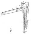
- Figures 3-5 are side elevations showing the computerin closed, partially open and fully open positionsrespectively;
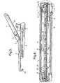
- Figure 6 is a cross-section taken on the line 6-6 inFigure 2; and,
- Figure 7 is an enlarged view of detail A in Figure 6.
- The computer shown in the drawings comprises a casinghaving a first,
upper leaf 1 which is hinged at 2 to asecond,lower leaf 3. Theupper leaf 1 supports a touchscreen 4 while the lower leaf supports akeyboard 5. Inaddition, a microprocessor (not shown) is mounted withinthelower leaf 3 and is attached to thekeyboard 5 and thetouch screen 4. Thelower leaf 3 is slidably mounted on abase 6. The rear section of thebase 6 incorporates abattery housing 7 (Figures 3-5) for supplying power to themicroprocessor. - In its closed position (Figures 2 and 3) the
upperleaf 1 is folded over thebase 6 and it will be seen thatthelower leaf 3 has retracted into thebase 6 so as to besubstantially invisible in the closed position. - The
upper leaf 1 is connected to thebase 6 via atorsion spring 8 having a pair of laterally spacedarms hook 11. Eachhook 11 is received inarespective aperture 12 in the side of thecasing 1. Acentral section 13 of thetorsion spring 8 is formed intoa U-shape and is clamped onto amounting 14, fixed to thebase 6, byclamp members 15. Thetorsion spring 8 isformed to as to define an over centre mechanism urging theleaf 1 either into the closed position shown in Figure 3 orthe fully open position shown in Figure 5. - The
leaf 3 carrying thekeyboard 5 is slidably mountedto thebase 6 due to engagement between achassis member 16forming part of thebase 6 and abase member 17 of thekeyboard 5. The interlocking engagement between thechassis member 16 and thebase member 17 can be seen moreclearly in Figure 7. Thechassis member 16 is secured toasupport plate 18 while thebase member 17 of thekeyboard 5 rests slidably on thechassis member 16. - The
base member 17 has a number ofupstanding bosses 19 definingrespective bores 20 some of which are indicatedin Figure 6 and Figure 7. Eachboss 19 supports arespective key 21 of thekeyboard 15 which has, on itsunderside, a depending spigot (not shown) which is receivedwithin the cruciform shapedbore 20. The construction ofthe keyboard can have a variety of forms but in thepreferred arrangement is in accordance with the keyassembly described and claimed in our co-pending patentapplication of even date entitled "Key Assembly" andclaiming priority from British Patent Application No.9519557.4. - The operation of the casing can be seen most easily bycomparing Figures 3, 4 and 5. Thus, initially the casingis in its closed position as shown in Figure 3 in which the
leaf 1 rests on thebase 6 with theleaf 3 retracted. Theuser then grasps the free end of theleaf 1 and raises itas shown in Figure 4. This movement is against theresilience of thetorsion spring 8 which tends to urge theleaf 1 towards its closed position at this stage. As theleaf 1 is raised, it will pivot about thehooks 11 so thattheleaf 3 is slid forwardly along thebase 6. At the sametime, thetorsion spring 8 rotates about its longitudinalaxis. Further opening movement of theleaf 1 pushes theleaf 3 further forward until arear surface 24 of theleaf 1 engages parts of thetorsion spring arms leaves - In the fully open position, the user can press, eitherwith his finger or a suitable tool, the touch screen 4 andthe reaction force to this pressure will be provided by thepart of the
base 6 lying behind theleaf 1 since thedownward force is transmitted through thearms torsion spring 8 to the rest of the torsion spring andhence to thebase 6. Furthermore, the centre of gravity oftheleaf 1 overlies thebase 6 thus also reducing the riskof tipping movement. Similarly, pressure applied to keyson thekeyboard 5 will also not cause significant pivotingmovement of the computer. - For additional security, an L-
shaped lug 25 isprovided on a front end of theleaf 3 which can act as astabilising foot in the open position as shown in Figure 5and which, in the closed position, locks into an aperture(not shown) provided in the front edge of thebase 6 toprevent inadvertent opening of theleaf 1.
Claims (15)
- A casing for computing equipment, the casingcomprising first and second leaves for mounting thecomputer equipment, the leaves being hinged together so asto be movable between a folded position in which the firstleaf overlies the second, and an open position; and a baseto which the leaves are movably secured so as to allow thesecond leaf to slide relative to the base whereby in theopen position of the leaves part of the base extends underthe first leaf so as to provide a support to resist tippingmovement when pressure is applied to the first leaf.
- A casing according to claim 1, wherein the leaves aresecured to the base by a hinge mechanism extending betweenthe first leaf and the base whereby pivotal movement of thefirst leaf relative to the second leaf causes slidingmovement of the second leaf relative to the base.
- A casing according to claim 2, wherein the hingemechanism comprises a pair of laterally spaced arms eachcoupled at one end to the first leaf and pivoted to thebase at the other end.
- A casing according to any of the preceding claims,further comprising an urging mechanism for urging theleaves towards at least one of the folded and openpositions.
- A casing according to claim 4, wherein the urgingmechanism comprises an over centre mechanism.
- A casing according to claim 5, wherein the urgingmechanism comprises a torsion spring.
- A casing according to any of claims 4 to 6, whendependent on at least claim 2, wherein the urging mechanismforms part of the hinge mechanism.
- A casing according to claim 7, when dependent on atleast claims 3 and 6, wherein the pair of arms are coupledto the torsion spring.
- A casing according to claim 8, wherein the pair ofarms and the torsion spring are formed from a single wire.
- A casing according to any of the preceding claims,wherein the overall dimensions of the casing in the foldedposition do not exceed 170mm x 90mm x 23mm.
- A casing according to any of the preceding claims,wherein the base has similar dimensions in plan to thesecond leaf so that in the closed position the second leafsubstantially covers the base.
- Computing equipment mounted in a casing according toany of the preceding claims, the computing equipmentincluding a display mounted in the first leaf and an inputdevice mounted in the second leaf.
- Computing equipment according to claim 12, wherein thedisplay includes a touch sensitive screen.
- Computing equipment according to claim 12 or claim 13,wherein the input device comprises a key pad.
- Portable computing equipment according to any ofclaims 12 to 14.
Applications Claiming Priority (2)
| Application Number | Priority Date | Filing Date | Title |
|---|---|---|---|
| GB9519556 | 1995-09-26 | ||
| GBGB9519556.6AGB9519556D0 (en) | 1995-09-26 | 1995-09-26 | Casing for computing equipment |
Publications (2)
| Publication Number | Publication Date |
|---|---|
| EP0766166A1 EP0766166A1 (en) | 1997-04-02 |
| EP0766166B1true EP0766166B1 (en) | 2003-07-09 |
Family
ID=10781245
Family Applications (1)
| Application Number | Title | Priority Date | Filing Date |
|---|---|---|---|
| EP96306974AExpired - LifetimeEP0766166B1 (en) | 1995-09-26 | 1996-09-25 | Casing for computing equipment |
Country Status (5)
| Country | Link |
|---|---|
| US (1) | US5742475A (en) |
| EP (1) | EP0766166B1 (en) |
| JP (1) | JPH09190243A (en) |
| DE (1) | DE69628984T2 (en) |
| GB (1) | GB9519556D0 (en) |
Families Citing this family (42)
| Publication number | Priority date | Publication date | Assignee | Title |
|---|---|---|---|---|
| US6870730B2 (en) | 1995-09-26 | 2005-03-22 | Psion-Computers Plc | Computer with a pen or touch sensitive display |
| US5973734A (en) | 1997-07-09 | 1999-10-26 | Flashpoint Technology, Inc. | Method and apparatus for correcting aspect ratio in a camera graphical user interface |
| US6028768A (en)* | 1997-07-30 | 2000-02-22 | International Business Machines Corporation | Mechanism for deploying a keyboard for a portable computer |
| US6097595A (en)* | 1997-12-10 | 2000-08-01 | International Business Machines Corporation | Mechanism for automatic deployment of legs for portable personal computer for enhanced cooling |
| GB2333005A (en)* | 1998-01-05 | 1999-07-07 | Siemens Ag | A device comprising a computer and integrated telecommunication apparatus |
| GB9800120D0 (en)* | 1998-01-05 | 1998-03-04 | Siemens Ag | Device comprising a computer and integrated telecommunication apparatus |
| US6078495A (en)* | 1998-01-28 | 2000-06-20 | International Business Machines Corporation | Apparatus and method for moving keyboard and display for enhanced cooling on portable computers |
| US6201688B1 (en)* | 1998-10-06 | 2001-03-13 | Micron Electronics, Inc. | Apparatus for securing a laptop computer |
| US6266235B1 (en) | 1998-10-06 | 2001-07-24 | Micron Technology, Inc. | Method for securing a laptop computer |
| US6317141B1 (en) | 1998-12-31 | 2001-11-13 | Flashpoint Technology, Inc. | Method and apparatus for editing heterogeneous media objects in a digital imaging device |
| US6351372B1 (en)* | 1999-09-01 | 2002-02-26 | Ericsson Inc. | Personal computing device with foldable keyboard |
| GB9922910D0 (en)* | 1999-09-28 | 1999-12-01 | Psion Computers Plc | Computer with a pen or touch sensitive display |
| FI19992564A7 (en)* | 1999-11-30 | 2001-05-31 | Nokia Corp | Hinge structure and hinged electronic device |
| US6781077B2 (en) | 2000-12-14 | 2004-08-24 | Think Outside, Inc. | Keyswitch and actuator structure |
| US6798649B1 (en) | 2002-02-25 | 2004-09-28 | Think Outside, Inc. | Mobile computer with foldable keyboard |
| US7015678B2 (en)* | 2004-06-22 | 2006-03-21 | Dialog Semiconductor Gmbh | Efficiency improvement of DC-DC converter |
| US7522945B2 (en) | 2005-06-28 | 2009-04-21 | Nokia Corporation | Portable electronic device |
| US7719826B1 (en)* | 2005-07-01 | 2010-05-18 | Apple Inc. | Integrated access cover |
| US7725988B2 (en)* | 2006-02-15 | 2010-06-01 | Lg Electronics Inc. | Hinge assembly and mobile device having the same |
| US9224145B1 (en) | 2006-08-30 | 2015-12-29 | Qurio Holdings, Inc. | Venue based digital rights using capture device with digital watermarking capability |
| TWM310362U (en)* | 2006-10-30 | 2007-04-21 | Quanta Comp Inc | Electronic apparatus |
| TW200848983A (en)* | 2007-06-05 | 2008-12-16 | Asustek Comp Inc | Portable electronic device |
| USD601557S1 (en) | 2007-08-06 | 2009-10-06 | Data Ltd., Inc. | Tablet computer |
| US7823253B2 (en)* | 2008-02-11 | 2010-11-02 | Shin Zu Shing Co., Ltd. | Slidable dual-axis hinge assembly |
| CN101571733A (en)* | 2008-04-28 | 2009-11-04 | 鸿富锦精密工业(深圳)有限公司 | Portable electronic equipment |
| CN101369173B (en)* | 2008-06-18 | 2015-08-12 | 秦彪 | portable computer |
| US9234372B2 (en)* | 2009-05-28 | 2016-01-12 | Paul Joseph Weber | Article security systems and devices |
| USD635568S1 (en) | 2009-06-09 | 2011-04-05 | Data Ltd., Inc. | Tablet computer |
| USD654499S1 (en) | 2009-06-09 | 2012-02-21 | Data Ltd., Inc. | Tablet computer |
| USD638834S1 (en) | 2009-10-05 | 2011-05-31 | Data Ltd., Inc. | Tablet computer |
| USD668657S1 (en) | 2010-09-01 | 2012-10-09 | Data Ltd., Inc. | Tablet computer cradle |
| CN102096444A (en)* | 2010-12-28 | 2011-06-15 | 富泰华工业(深圳)有限公司 | Electronic device with liftable keyboard |
| USD690296S1 (en) | 2011-02-01 | 2013-09-24 | Data Ltd., Inc. | Tablet computer |
| USD662502S1 (en) | 2011-02-15 | 2012-06-26 | Data Ltd., Inc. | Tablet computer cradle |
| US8804318B2 (en)* | 2012-02-29 | 2014-08-12 | Blackberry Limited | Storable keyboard having variable angular orientations |
| US8549708B1 (en)* | 2012-07-05 | 2013-10-08 | Khvatec Co., Ltd. | Long stroke tilting hinge module for portable terminal |
| US11086355B2 (en)* | 2016-10-31 | 2021-08-10 | Lenovo (Singapore) Pte. Ltd. | Electronic device with collapsing interface components |
| TWI638256B (en)* | 2017-06-14 | 2018-10-11 | 華碩電腦股份有限公司 | Interlocking assembly and electronic device |
| TWI683206B (en)* | 2018-11-27 | 2020-01-21 | 宏碁股份有限公司 | Electronic device |
| US11221654B2 (en)* | 2019-04-01 | 2022-01-11 | Compal Electronics, Inc. | Electronic device |
| US11092997B2 (en)* | 2019-09-26 | 2021-08-17 | Apple Inc. | Sliding input device cover |
| WO2022251214A1 (en)* | 2021-05-25 | 2022-12-01 | Vertiv It Systems, Inc. | Low profile keyboard monitor and mouse system |
Family Cites Families (5)
| Publication number | Priority date | Publication date | Assignee | Title |
|---|---|---|---|---|
| JP2734033B2 (en)* | 1988-08-08 | 1998-03-30 | ソニー株式会社 | Display device support mechanism |
| EP0534976A4 (en)* | 1990-05-04 | 1993-06-16 | Grid Systems Corporation | Combination laptop and pad computer |
| US5168426A (en)* | 1991-08-16 | 1992-12-01 | Beaver Computer Corporation | Hinge mechanism for cover panel of portable computer including slide mechanism |
| JPH0635565A (en)* | 1992-07-13 | 1994-02-10 | Fujitsu Ltd | Portable information equipment |
| US5543787A (en)* | 1994-03-23 | 1996-08-06 | International Business Machines Corporation | Keyboard with translating sections |
- 1995
- 1995-09-26GBGBGB9519556.6Apatent/GB9519556D0/enactivePending
- 1996
- 1996-09-23USUS08/723,882patent/US5742475A/ennot_activeExpired - Fee Related
- 1996-09-25EPEP96306974Apatent/EP0766166B1/ennot_activeExpired - Lifetime
- 1996-09-25DEDE69628984Tpatent/DE69628984T2/ennot_activeExpired - Lifetime
- 1996-09-26JPJP8254088Apatent/JPH09190243A/enactivePending
Also Published As
| Publication number | Publication date |
|---|---|
| JPH09190243A (en) | 1997-07-22 |
| DE69628984D1 (en) | 2003-08-14 |
| DE69628984T2 (en) | 2004-04-22 |
| US5742475A (en) | 1998-04-21 |
| EP0766166A1 (en) | 1997-04-02 |
| GB9519556D0 (en) | 1995-11-29 |
Similar Documents
| Publication | Publication Date | Title |
|---|---|---|
| EP0766166B1 (en) | Casing for computing equipment | |
| US5539615A (en) | Notebook computer keyboard with slot-supported sliding pin tilt mechanism | |
| US6870730B2 (en) | Computer with a pen or touch sensitive display | |
| US6104604A (en) | Modular keyboard | |
| US5339213A (en) | Portable computer touch pad attachment | |
| JP3073121B2 (en) | Display device exterior structure | |
| US5915661A (en) | Collapsible desk stand for portable computer | |
| KR100204158B1 (en) | Computers With a Separate Keyboard and a Separate Keyboard | |
| US6025986A (en) | Retractable palmrest for keyboard-equipped electronic products | |
| US6462937B1 (en) | Computer having an integrated gaming control pad | |
| WO1996016367A2 (en) | Concealed locking assembly for a removable portable computer keyboard | |
| US20030100338A1 (en) | Personal digital assistant cover with an integrated keypad | |
| US20030063432A1 (en) | All-in-one personal computer with tool-less quick-release features for various elements thereof including a reusable thin film transistor monitor | |
| US6564429B2 (en) | Hinge system for a portable computer | |
| US20040168486A1 (en) | Laptop computer lock having a tapered extension extending out to allow a securing device to securely lock the laptop computer without tilting the laptop computer | |
| JPH0719186B2 (en) | Computer and display device with input function | |
| US20030063059A1 (en) | Method and apparatus for reusing a flat panel monitor | |
| US5570268A (en) | Stowable wrist rest for portable computers | |
| US7471508B2 (en) | System and method for locking computer | |
| JP2003168876A (en) | Electronics | |
| JP2895016B2 (en) | Keyboard mount and its use | |
| JP3105810B2 (en) | Lock and height adjustment mechanism for notebook computers | |
| US6808326B2 (en) | Keyboard with a supporting device | |
| CN223297624U (en) | Bracket structure and electronic product protective cover | |
| JP4353566B2 (en) | OA equipment storage panel |
Legal Events
| Date | Code | Title | Description |
|---|---|---|---|
| PUAI | Public reference made under article 153(3) epc to a published international application that has entered the european phase | Free format text:ORIGINAL CODE: 0009012 | |
| AK | Designated contracting states | Kind code of ref document:A1 Designated state(s):DE FR GB | |
| 17P | Request for examination filed | Effective date:19970926 | |
| GRAH | Despatch of communication of intention to grant a patent | Free format text:ORIGINAL CODE: EPIDOS IGRA | |
| GRAH | Despatch of communication of intention to grant a patent | Free format text:ORIGINAL CODE: EPIDOS IGRA | |
| GRAA | (expected) grant | Free format text:ORIGINAL CODE: 0009210 | |
| AK | Designated contracting states | Designated state(s):DE FR GB | |
| REG | Reference to a national code | Ref country code:GB Ref legal event code:FG4D | |
| REF | Corresponds to: | Ref document number:69628984 Country of ref document:DE Date of ref document:20030814 Kind code of ref document:P | |
| ET | Fr: translation filed | ||
| PLBE | No opposition filed within time limit | Free format text:ORIGINAL CODE: 0009261 | |
| STAA | Information on the status of an ep patent application or granted ep patent | Free format text:STATUS: NO OPPOSITION FILED WITHIN TIME LIMIT | |
| 26N | No opposition filed | Effective date:20040414 | |
| REG | Reference to a national code | Ref country code:DE Ref legal event code:R082 Ref document number:69628984 Country of ref document:DE Representative=s name:SCHUMACHER & WILLSAU PATENTANWALTSGESELLSCHAFT, DE Ref country code:DE Ref legal event code:R082 Ref document number:69628984 Country of ref document:DE Representative=s name:HOFFMANN - EITLE, DE | |
| REG | Reference to a national code | Ref country code:DE Ref legal event code:R082 Ref document number:69628984 Country of ref document:DE Representative=s name:SCHUMACHER & WILLSAU PATENTANWALTSGESELLSCHAFT, DE | |
| REG | Reference to a national code | Ref country code:DE Ref legal event code:R082 Ref document number:69628984 Country of ref document:DE Representative=s name:SCHUMACHER & WILLSAU PATENTANWALTSGESELLSCHAFT, DE Effective date:20130712 Ref country code:DE Ref legal event code:R082 Ref document number:69628984 Country of ref document:DE Representative=s name:SCHUMACHER & WILLSAU PATENTANWALTSGESELLSCHAFT, DE Effective date:20130805 Ref country code:DE Ref legal event code:R081 Ref document number:69628984 Country of ref document:DE Owner name:PSION HOLDINGS LTD., BASINGSTOKE, GB Free format text:FORMER OWNER: PSION PLC, LONDON, GB Effective date:20130805 Ref country code:DE Ref legal event code:R081 Ref document number:69628984 Country of ref document:DE Owner name:PSION HOLDINGS LTD., GB Free format text:FORMER OWNER: PSION PLC, LONDON, GB Effective date:20130805 | |
| REG | Reference to a national code | Ref country code:FR Ref legal event code:CJ Effective date:20130903 Ref country code:FR Ref legal event code:CD Owner name:PSION HOLDINGS LIMITED, GB Effective date:20130903 Ref country code:FR Ref legal event code:CA Effective date:20130903 | |
| REG | Reference to a national code | Ref country code:FR Ref legal event code:PLFP Year of fee payment:20 | |
| PGFP | Annual fee paid to national office [announced via postgrant information from national office to epo] | Ref country code:DE Payment date:20150922 Year of fee payment:20 Ref country code:GB Payment date:20150825 Year of fee payment:20 | |
| PGFP | Annual fee paid to national office [announced via postgrant information from national office to epo] | Ref country code:FR Payment date:20150824 Year of fee payment:20 | |
| REG | Reference to a national code | Ref country code:DE Ref legal event code:R071 Ref document number:69628984 Country of ref document:DE | |
| REG | Reference to a national code | Ref country code:GB Ref legal event code:PE20 Expiry date:20160924 | |
| PG25 | Lapsed in a contracting state [announced via postgrant information from national office to epo] | Ref country code:GB Free format text:LAPSE BECAUSE OF EXPIRATION OF PROTECTION Effective date:20160924 |