EP0762703A1 - Multicarrier demodulation with reduction of white frequency distortion - Google Patents
Multicarrier demodulation with reduction of white frequency distortionDownload PDFInfo
- Publication number
- EP0762703A1 EP0762703A1EP96460030AEP96460030AEP0762703A1EP 0762703 A1EP0762703 A1EP 0762703A1EP 96460030 AEP96460030 AEP 96460030AEP 96460030 AEP96460030 AEP 96460030AEP 0762703 A1EP0762703 A1EP 0762703A1
- Authority
- EP
- European Patent Office
- Prior art keywords
- samples
- distortion
- interpolation
- extrapolation
- estimates
- Prior art date
- Legal status (The legal status is an assumption and is not a legal conclusion. Google has not performed a legal analysis and makes no representation as to the accuracy of the status listed.)
- Granted
Links
- 238000000034methodMethods0.000claimsabstractdescription40
- 238000013213extrapolationMethods0.000claimsabstractdescription32
- 230000010363phase shiftEffects0.000claimsdescription6
- 230000002123temporal effectEffects0.000claimsdescription3
- 238000001914filtrationMethods0.000abstractdescription3
- 238000004364calculation methodMethods0.000description17
- 230000005540biological transmissionEffects0.000description11
- 230000000875corresponding effectEffects0.000description6
- 239000000969carrierSubstances0.000description3
- 230000001427coherent effectEffects0.000description3
- 230000000694effectsEffects0.000description3
- 230000002596correlated effectEffects0.000description2
- 239000013598vectorSubstances0.000description2
- 230000003466anti-cipated effectEffects0.000description1
- 230000001276controlling effectEffects0.000description1
- 238000010586diagramMethods0.000description1
- 238000002592echocardiographyMethods0.000description1
- 230000010355oscillationEffects0.000description1
- 238000011084recoveryMethods0.000description1
- 230000009466transformationEffects0.000description1
- 230000017105transpositionEffects0.000description1
Images

Classifications
- H—ELECTRICITY
- H04—ELECTRIC COMMUNICATION TECHNIQUE
- H04L—TRANSMISSION OF DIGITAL INFORMATION, e.g. TELEGRAPHIC COMMUNICATION
- H04L25/00—Baseband systems
- H04L25/02—Details ; arrangements for supplying electrical power along data transmission lines
- H04L25/0202—Channel estimation
- H04L25/0224—Channel estimation using sounding signals
- H04L25/0228—Channel estimation using sounding signals with direct estimation from sounding signals
- H04L25/023—Channel estimation using sounding signals with direct estimation from sounding signals with extension to other symbols
- H04L25/0232—Channel estimation using sounding signals with direct estimation from sounding signals with extension to other symbols by interpolation between sounding signals
- H—ELECTRICITY
- H04—ELECTRIC COMMUNICATION TECHNIQUE
- H04L—TRANSMISSION OF DIGITAL INFORMATION, e.g. TELEGRAPHIC COMMUNICATION
- H04L27/00—Modulated-carrier systems
- H04L27/26—Systems using multi-frequency codes
- H04L27/2601—Multicarrier modulation systems
- H04L27/2647—Arrangements specific to the receiver only
- H04L27/2655—Synchronisation arrangements
- H04L27/2657—Carrier synchronisation
- H—ELECTRICITY
- H04—ELECTRIC COMMUNICATION TECHNIQUE
- H04L—TRANSMISSION OF DIGITAL INFORMATION, e.g. TELEGRAPHIC COMMUNICATION
- H04L27/00—Modulated-carrier systems
- H04L27/26—Systems using multi-frequency codes
- H04L27/2601—Multicarrier modulation systems
- H04L27/2647—Arrangements specific to the receiver only
- H04L27/2655—Synchronisation arrangements
- H04L27/2668—Details of algorithms
- H04L27/2673—Details of algorithms characterised by synchronisation parameters
- H04L27/2675—Pilot or known symbols
Definitions
- the field of the inventionis that of the reception of multicarrier signals. More specifically, the invention relates to the correction of the distortion undergone by such a signal, with a view in particular to optimizing the demodulation of the symbols modulating this signal.
- distortionis meant here, as will be seen below, the white frequency disturbances, whether due to the transmission channel or to the receiver.
- the inventionapplies to all types of signals implementing a plurality of carrier frequencies, that is to say to systems implementing signals transmitted according to the frequency division multiplexing technique (in English: Frequency Multiplex Division (FDM)), and for example the COFDM system (Coded Orthogonal Frequency Division Multiplex (multiplexing of coded orthogonal frequencies)), implemented in particular within the framework of the European project Eureka 147 "DAB" (Digital Audio Broadcasting )), and also anticipated for the transmission of television signals by hertzian way or twisted pair for example.
- FDMFrequency Multiplex Division
- COFDM systemCoded Orthogonal Frequency Division Multiplex (multiplexing of coded orthogonal frequencies)
- DABDigital Audio Broadcasting
- the source data to be transmittedare organized into symbols (made up of one or more source data) each modulating, for a predetermined time interval, a carrier frequency chosen from a plurality of carriers.
- the signal formed by all of the modulated carriersis transmitted to one or more receivers, which receive an emitted signal disturbed by the transmission channel.
- Demodulationgenerally consists, in principle, of estimating the response of the transmission channel for each symbol, then dividing the signal received by this estimate to obtain an estimate of the symbol transmitted.
- demodulation techniquesare known, which can be differential or consistent.
- a technique facilitating coherent demodulation using reference symbols known to the receivers and regularly inserted among the useful symbolsis for example described in patent FR-90 01491 in the name of the same applicants.
- each carrier k of a symbol nis therefore modulated by a complex symbol C n, k .
- H n, kH n, k . VS n, k . ⁇ not + white noise
- White noiseis a term that is neglected later.
- ⁇ nis a complex term, a priori variable in phase and amplitude which depends only on n, and therefore describes any "white" frequency distortion which taints the received signal.
- the ⁇ nare assumed to be poorly correlated from symbol to symbol.
- the recovery by the receiver of the information C n, k transmittedimplies knowing how to isolate the term C n, k from equation (1), by division of the Y n, k received by an estimated value of H n, k . ⁇ n .
- the state of the artconsists in first obtaining an estimate of the product H n, k . ⁇ n , denoted D n, k (D as "distortion") in the following, for certain couples (n, k) of Z x Z.
- D n, kD as "distortion"
- P 2the subset of Z x Z formed by the pairs (n, k) for which a first value of D n, k is estimated by the receiver.
- One way often used to obtain such a subsetconsists of inserting "pilots" (or reference symbols) into the frame, that is to say for certain values of k and n - predetermined in advance and known to the receiver - particular values C n, k a priori known to the receiver. This method is only an example, however, and any other suitable method can be used.
- the D ⁇ n values 0 , k 0 for all the values n 0 and k 0 possible in Zare then calculated by the receiver by interpolation and / or extrapolation of the values D n, k , with (n, k) belonging to P 2 .
- the state of the artconsists in defining the function f (n 0 , k 0 ) for calculating D ⁇ n 0 , k 0 , from D n, k , (n, k) belonging to P 2 .
- the inventionparticularly aims to overcome these drawbacks.
- an objective of the present inventionis to provide a method for estimating the distortion undergone by a multicarrier signal, and a corresponding device, making it possible in particular to optimize the demodulation of the symbols forming the received signal:
- the inventionaims to provide such a method, taking into account the distortions induced by the receivers.
- Another objective of the inventionis to provide such a demodulation method, in which the estimation of the response of the transmission channel is optimized, whatever the distortions induced by the receivers.
- the inventionproposes to improve the estimation of the distortions, by correcting the reference information used for this estimation, prior to the corresponding estimation calculation, so that this reference information reflects, at all times reception, the same distortions as the symbols received.
- each of said reference estimates (D n, k )is affected by a distortion substantially equal to the distortion undergone by the signal received between the time of reception (n) of the samples used for the determination of said estimates of reference (D n, k ) and the time interval (n 0 ) considered.
- the reference elementsare therefore affected by the same distortion as the symbols to be demodulated. In other words, it is not sought, according to the invention, to suppress the effect on the estimation of the white frequency distortions, but one makes sure that it is compensated. In other words, it is a relative approach to correcting the effects of white frequency distortion.
- said estimate (D ⁇ '' n, k )can in particular be used to divide the sample received (Y n 0 , k 0 ), so as to deliver an estimated source symbol ( ⁇ '' n, k ).
- said reference samplescorrespond to pilots, of value and of position in time-frequency space known to the receivers. This technique is of course known in itself.
- said information ( ⁇ n ) representative of the distortion induced by the receiveris obtained by analysis of one or more pilot frequencies carrying continuously fixed reference information known to the receivers.
- the interpolation and / or extrapolation operationcomprises a frequency interpolation and / or extrapolation step followed by a temporal interpolation and / or extrapolation step
- the step of correcting the reference estimatesis carried out between said step of frequency interpolation and / or extrapolation and said step of time interpolation and / or extrapolation.
- the inventionalso relates to the distortion correction devices implementing such a method.
- such a devicecomprising means for determining reference estimates (D n, k ) previously determined for certain samples, belonging to a set of reference samples ( P 2 ), and interpolation means and / or extrapolation of an estimate ( D ⁇ not 0 , k 0 '' ) of said distortion for each of the samples received (Y n 0 , k 0 ), from said reference estimates (D n, k ), comprises means for calculating information representative of the variation in the white frequency distortion induced on the samples received, between the time of reception (n) of the samples used to determine said reference estimates (D n, k ) and a given time interval (n 0 ), and means for correcting each reference estimate (D n, k ) supplied to said interpolation means and / or extrapolation, as a function of said information representative of the variation of said distortion induced by the receiver.
- the known technique for estimating the distortions undergone by the symbols of a multicarrier signalconsists in defining a function f (n 0 , k 0 ) for calculating D ⁇ n 0 , k 0 for all n 0 and k 0 of Z , from the D n, k , (n, k) belonging to P 2 .
- the inventionis applicable to any function f. It improves the estimation of D ⁇ n 0 , k 0 from the calculation of f (n 0 , k 0 ), by first modifying the D n, k , (n, k) belonging to P 2 which serve as the basis for this calculation, without prejudging the way in which these D n, k have been obtained.
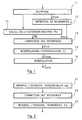
- FIG. 1illustrates in general the method of the invention, as it is inserted in the processing of a multicarrier signal.
- the transmitted signalis first of all, during a first known reception step 11, restored in the form of symbols Y n 0 , k 0 as described in the preamble. According to any method, we obtain (12) the series of references D n, k .
- a first known way, implemented to facilitate the coherent demodulation of the received signalconsists in inserting on transmission into the frame "pilots", that is to say to transmit for certain values of k and n, predetermined and known to the receptors, particular values C n, k and known a priori to the receptors.
- This techniqueis notably presented in the patent document FR-90 01491 already cited.
- D n 0 -i, k 0is assumed to be obtained elsewhere in the receiver.
- ⁇ nAnother technique allowing the determination of ⁇ n is the continuous transmission, on at least one carrier frequency, of a continuous reference. The calculation is then direct, by simple comparison between two consecutive reception instants.
- a step 14is provided for correcting the references D n, k , (n, k) belonging to P 2 , before the interpolation / extrapolation 15.
- This correctionconsists in compensating, at each reception instant, l effect of ⁇ n .
- the correction step 14simply consists in replacing D n 0 -i, k 0 by : D not 0 -i, k 0 . ⁇ not 0 ⁇ not 0 -i with i small, and for example equal to 1.
- ⁇ ncan describe the instantaneous frequency variations of the local oscillator (or oscillators) of the receiver, necessarily imperfect, or at least the value averaged over the duration of a symbol of these variations.
- phase noise⁇ n can then be noted ej ⁇ n .
- FIG. 1illustrates, for the sake of simplification, a series of successive steps, it is clear that certain calculations can be made in parallel.
- FIG. 2illustrates a particular embodiment of the invention, in which the operation f (n 0 , k 0 ) of interpolation and / or of extrapolation can be broken down into a function g of interpolation and / or frequency extrapolation 21 followed by an interpolation and / or temporal extrapolation function h 22, it may be advantageous (but this is not compulsory), for reasons of simplicity, to insert the step correction 23 of the invention between the calculations of g (21) and h (22), and no longer before the calculation of g.
- FIG. 3illustrates in a simplified manner a particular embodiment of a receiver implementing the invention.
- the received signal 31is first of all transposed into low frequency by a multiplier 32 controlled by a local oscillator 33 delivering the transposition frequency f 0 . Then the transposed signal is filtered by a low-pass or band-pass filter 34, and converted into a digital signal by a sampler 35. Then, a module 36 for generating the components in phase and in quadrature delivers the channels 37 I and 37 Q.
- channels I and Qare subjected to a mathematical transformation FFT 38, which delivers the samples 39 Y n0, k0 .
- the Y n 0 , k 0 39are demodulated (310) according to the method described above, by division by D ⁇ not 0 , k 0 '' 312 to provide the estimated symbols VS ⁇ not 0 , k 0 '' 313, which then conventionally undergo channel decoding 314, then the rest of the processing until the source signal is restored.
- the Y n 0 , k 39also supply a module 315 for extracting the pilots D n, k which undergo a first frequency filtering 316 then a second time filtering 317 to provide D ⁇ not 0 , k 0 '' 312 to the demodulator 310.
- a correction module 311is inserted between the two filter modules 316 and 317 to modify the data delivered by the analysis modules of the pilots 315 and 316.
- This correctiontakes account of information 318 of distortion ( phase noise of the receiver in particular), delivered by a module 319 for calculating this distortion.
- this module 319is already present in certain receivers, in particular for controlling the local oscillator 33 and / or the I / Q generator 36.
Landscapes
- Engineering & Computer Science (AREA)
- Computer Networks & Wireless Communication (AREA)
- Signal Processing (AREA)
- Power Engineering (AREA)
- Noise Elimination (AREA)
- Digital Transmission Methods That Use Modulated Carrier Waves (AREA)
Abstract
Description
Translated fromFrenchLe domaine de l'invention est celui de la réception de signaux multiporteuses. Plus précisément, l'invention concerne la correction de la distorsion subie par un tel signal, en vue notamment de l'optimisation de la démodulation des symboles modulant ce signal. Par distorsion, on entend ici, comme on le verra par la suite, les perturbations blanches en fréquence, qu'elles soient dues au canal de transmission ou au récepteur.The field of the invention is that of the reception of multicarrier signals. More specifically, the invention relates to the correction of the distortion undergone by such a signal, with a view in particular to optimizing the demodulation of the symbols modulating this signal. By distortion is meant here, as will be seen below, the white frequency disturbances, whether due to the transmission channel or to the receiver.
L'invention s'applique à tous les types de signaux mettant en oeuvre une pluralité de fréquences porteuses, c'est-à-dire aux systèmes mettant en oeuvre des signaux transmis selon la technique de multiplexage par répartition en fréquence (en anglais : Frequency Division Multiplex (FDM)), et par exemple le système COFDM (Coded Orthogonal Frequency Division Multiplex (multiplexage de fréquences orthogonales codées)), mis en oeuvre notamment dans le cadre du projet européen Eurêka 147 "DAB" (Digital Audio Broadcasting (diffusion audionumérique)), et également pressenti pour la transmission de signaux de télévision par voie hertzienne ou paire torsadée par exemple.The invention applies to all types of signals implementing a plurality of carrier frequencies, that is to say to systems implementing signals transmitted according to the frequency division multiplexing technique (in English: Frequency Multiplex Division (FDM)), and for example the COFDM system (Coded Orthogonal Frequency Division Multiplex (multiplexing of coded orthogonal frequencies)), implemented in particular within the framework of the European project Eureka 147 "DAB" (Digital Audio Broadcasting )), and also anticipated for the transmission of television signals by hertzian way or twisted pair for example.
Dans de tels systèmes de transmission, les données source à transmettre sont organisées en symboles (constitués d'une ou plusieurs données source) modulant chacun, pendant un intervalle de temps prédéterminé, une fréquence porteuse choisie parmi une pluralité de porteuses. Le signal formé par l'ensemble des porteuses modulées est transmis vers un ou plusieurs récepteurs, qui reçoivent un signal émis perturbé par le canal de transmission.In such transmission systems, the source data to be transmitted are organized into symbols (made up of one or more source data) each modulating, for a predetermined time interval, a carrier frequency chosen from a plurality of carriers. The signal formed by all of the modulated carriers is transmitted to one or more receivers, which receive an emitted signal disturbed by the transmission channel.
La démodulation consiste généralement, dans son principe, à estimer la réponse du canal de transmission pour chaque symbole, puis à diviser le signal reçu par cette estimation pour obtenir une estimation du symbole émis.Demodulation generally consists, in principle, of estimating the response of the transmission channel for each symbol, then dividing the signal received by this estimate to obtain an estimate of the symbol transmitted.
On connaît de nombreuses techniques de démodulation, qui peut être différentielle ou cohérente. Une technique facilitant la démodulation cohérente à l'aide de symboles de référence connus des récepteurs et régulièrement insérés parmi les symboles utiles est par exemple décrite dans le brevet FR-90 01491 au nom des mêmes déposants.Many demodulation techniques are known, which can be differential or consistent. A technique facilitating coherent demodulation using reference symbols known to the receivers and regularly inserted among the useful symbols is for example described in patent FR-90 01491 in the name of the same applicants.
Le problème majeur de ces techniques connues est que l'estimation de la réponse du canal obtenue n'est pas toujours exacte ni précise, car elle peut être perturbée par une distorsion blanche en fréquence induite par le récepteur ou dans une moindre mesure pour l'émetteur.The major problem with these known techniques is that estimating the response of the channel obtained is not always exact or precise, because it can be disturbed by a white frequency distortion induced by the receiver or to a lesser extent for the transmitter.
En d'autres termes, en convenant de noter, dans un système multiporteuse, n l'indice temporel et k l'indice fréquentiel (n et k appartenant àZ), à l'émission, chaque porteuse k d'un symbole n est donc modulée par un symbole Cn,k complexe.In other words, by agreeing to note, in a multicarrier system, n the time index and k the frequency index (n and k belonging toZ ), at transmission, each carrier k of a symbol n is therefore modulated by a complex symbol Cn, k .
Si l'on note Hn,k la réponse complexe du canal de transmission, alors on reçoit :
Le bruit blanc est un terme que l'on néglige par la suite.White noise is a term that is neglected later.
⌀n est un terme complexe, a priori variable en phase et amplitude qui ne dépend que de n, et décrit donc n'importe quelle distorsion "blanche" en fréquence qui entache le signal reçu. Les ⌀n sont supposés peu corrélés de symbole en symbole.⌀n is a complex term, a priori variable in phase and amplitude which depends only on n, and therefore describes any "white" frequency distortion which taints the received signal. The ⌀n are assumed to be poorly correlated from symbol to symbol.
Le recouvrement par le récepteur de l'information Cn,k transmise implique de savoir isoler le terme Cn,k à partir de l'équation (1), par division du Yn,k reçu par une valeur estimée de Hn,k .⌀n.The recovery by the receiver of the information Cn, k transmitted implies knowing how to isolate the term Cn, k from equation (1), by division of the Yn, k received by an estimated value of Hn, k .⌀n .
L'état de l'art consiste à obtenir d'abord une estimation du produit Hn,k .⌀n, notée Dn,k (D comme "distorsion") dans la suite, pour certains couples (n,k) deZxZ. On noteP2 le sous-ensemble deZxZ formé des couples (n,k) pour lesquels une première valeur de Dn,k est estimée par le récepteur.The state of the art consists in first obtaining an estimate of the product Hn, k .⌀n , denoted Dn, k (D as "distortion") in the following, for certain couples (n, k) ofZ xZ. We denote byP2 the subset ofZ xZ formed by the pairs (n, k) for which a first value of Dn, k is estimated by the receiver.
Une façon souvent utilisée pour obtenir un tel sous-ensemble consiste à insérer à l'émission dans la trame des "pilotes" (ou symboles de référence), c'est-à-dire à émettre pour certaines valeurs de k et de n - prédéterminées à l'avance et connues du récepteur - des valeurs Cn,k particulières a priori connues du récepteur. Cette méthode n'est toutefois qu'un exemple, et tout autre méthode adéquate peut être utilisée.One way often used to obtain such a subset consists of inserting "pilots" (or reference symbols) into the frame, that is to say for certain values of k and n - predetermined in advance and known to the receiver - particular values Cn, k a priori known to the receiver. This method is only an example, however, and any other suitable method can be used.
Les valeurs D̂n
L'état de l'art consiste à définir la fonction f(n0,k0) de calcul de D̂n
Un problème majeur, détecté par les inventeurs mais non expressément connu de l'homme du métier, vient du fait que le D̂n
L'invention a notamment pour objectif de pallier ces inconvénients.The invention particularly aims to overcome these drawbacks.
Ainsi, un objectif de la présente invention est de fournir un procédé d'estimation de la distorsion subie par un signal multiporteuse, et un dispositif correspondant, permettant notamment d'optimiser la démodulation des symboles formant le signal reçu:Thus, an objective of the present invention is to provide a method for estimating the distortion undergone by a multicarrier signal, and a corresponding device, making it possible in particular to optimize the demodulation of the symbols forming the received signal:
Plus précisément, l'invention a pour objectif de fournir un tel procédé, tenant compte des distorsions induites par les récepteurs.More specifically, the invention aims to provide such a method, taking into account the distortions induced by the receivers.
Un autre objectif de l'invention est de fournir un tel procédé de démodulation, dans lequel l'estimation de la réponse du canal de transmission est optimisée, quelques soient les distorsions induites par les récepteurs.Another objective of the invention is to provide such a demodulation method, in which the estimation of the response of the transmission channel is optimized, whatever the distortions induced by the receivers.
Ces objectifs, ainsi que d'autres qui apparaîtront par la suite, sont atteints selon l'invention par un procédé de correction de la distorsion subie par un signal multiporteuse formé de symboles modulant une pluralité de fréquences porteuses,
selon lequel on détermine par interpolation et/ou extrapolation une estimation (
procédé selon lequel chaque estimation de référence (Dn,k) est corrigée préalablement à ladite interpolation et/ou à ladite extrapolation, pour chaque intervalle de temps (n0), en fonction d'une information représentative de la variation de la distorsion blanche en fréquences induite sur les échantillons reçus, entre l'instant de réception (n) des échantillons servant à la détermination desdites estimations de référence (Dn,k) et l'intervalle de temps (n0) considéré.These objectives, as well as others which will appear subsequently, are achieved according to the invention by a method of correcting the distortion undergone by a multicarrier signal formed by symbols modulating a plurality of carrier frequencies,
whereby an estimate is determined by interpolation and / or extrapolation (
method according to which each reference estimate (Dn, k ) is corrected before said interpolation and / or said extrapolation, for each time interval (n0 ), as a function of information representative of the variation of the white distortion in frequency induced on the samples received, between the instant of reception (n) of the samples used for the determination of said reference estimates (Dn, k ) and the time interval (n0 ) considered.
En d'autres termes, l'invention propose d'améliorer l'estimation des distorsions, en corrigeant les informations de référence utilisées pour cette estimation, préalablement au calcul correspondant d'estimation, de façon que ces informations de référence reflètent, à chaque instant de réception, les mêmes distorsions que les symboles reçus.In other words, the invention proposes to improve the estimation of the distortions, by correcting the reference information used for this estimation, prior to the corresponding estimation calculation, so that this reference information reflects, at all times reception, the same distortions as the symbols received.
Ainsi, de façon avantageuse, on affecte chacune desdites estimations de référence (Dn,k) d'une distorsion sensiblement égale à la distorsion subie par le signal reçu entre l'instant de réception (n) des échantillons servant à la détermination desdites estimations de référence (Dn,k) et l'intervalle de temps (n0) considéré.Thus, advantageously, each of said reference estimates (Dn, k ) is affected by a distortion substantially equal to the distortion undergone by the signal received between the time of reception (n) of the samples used for the determination of said estimates of reference (Dn, k ) and the time interval (n0 ) considered.
Les éléments de référence se voient donc affectés de la même distorsion que les symboles à démoduler. En d'autres termes, on ne cherche pas, selon l'invention, à supprimer l'effet sur l'estimation des distorsions blanches en fréquences, mais on fait en sorte qu'il soit compensé. En d'autres termes encore, il s'agit d'une approche relative de la correction des effets de la distorsion blanche en fréquence.The reference elements are therefore affected by the same distortion as the symbols to be demodulated. In other words, it is not sought, according to the invention, to suppress the effect on the estimation of the white frequency distortions, but one makes sure that it is compensated. In other words, it is a relative approach to correcting the effects of white frequency distortion.
Avantageusement, le procédé de l'invention comprend les étapes suivantes :
- détermination de l'écart relatif de distorsion (ψn ∈ C) induite par le récepteur entre deux intervalles de temps (n-1 et n) consécutif,

- pour chaque échantillon reçu (Yn
0 ,k0 ), correction des estimations de référence (Dn,k) à prendre en compte de la façon suivante :
- interpolation et/ou extrapolation par f d'une estimation (D̂


0 ,k0 ).


- determination of the relative difference in distortion (ψn ∈ C ) induced by the receiver between two consecutive time intervals (n-1 and n),
- for each sample received (Yn
0 , k0 ), correction of the reference estimates (Dn, k ) to be taken into account as follows: - interpolation and / or extrapolation by f of an estimate (D̂
0 , k0 ).
De façon avantageuse, notamment lorsque les distorsions blanches en fréquence correspondent essentiellement à des variations instantanées (ou du moins à leurs moyennes sur la durée d'un symbole) de la fréquence d'oscillation d'un ou plusieurs oscillateurs et peuvent s'écrire φn = ej

Comme indiqué précédemment, ladite estimation (D̂

Selon un mode de réalisation préférentiel de l'invention, correspondant à une démodulation cohérente, lesdits échantillons de référence correspondent à des pilotes, de valeur et de position dans l'espace temps-fréquence connues des récepteurs. Cette technique est bien sûr connue en elle-même.According to a preferred embodiment of the invention, corresponding to a coherent demodulation, said reference samples correspond to pilots, of value and of position in time-frequency space known to the receivers. This technique is of course known in itself.
Selon un autre mode de réalisation, correspondant à une démodulation différentielle, lesdits échantillons de référence sont obtenus de la façon suivante :
De façon avantageuse, ladite information (ψn) représentative de la distorsion induite par le récepteur peut être obtenue, pour chaque échantillon reçu, de la façon suivante :
- décision dure de la valeur de chacun desdits échantillons, par association à chacun desdits échantillons de l'élément de données le plus probable, parmi une constellation d'éléments de données formant un alphabet de modulation ;
- détermination d'un décalage de phase entre chacun desdits échantillons et son élément de donnée associé ;
- estimation de ladite information (ψn), en fonction de plusieurs décalages de phase correspondant à des fréquences porteuses différentes et à un même intervalle de temps.
- hard decision of the value of each of said samples, by association with each of said samples of the most likely data element, from among a constellation of data elements forming a modulation alphabet;
- determining a phase shift between each of said samples and its associated data element;
- estimation of said information (ψn ), as a function of several phase shifts corresponding to different carrier frequencies and at the same time interval.
Cette technique est également connue en elle-même, et décrite en particulier dans la demande de brevet FR-94 07984 au nom des mêmes déposants.This technique is also known in itself, and described in particular in patent application FR-94 07984 in the name of the same applicants.
Selon un autre mode de réalisation avantageux, ladite information (ψn) représentative de la distorsion induite par le récepteur est obtenue par analyse d'une ou plusieurs fréquences pilotes portant en continu une information de référence fixe et connue des récepteurs.According to another advantageous embodiment, said information (ψn ) representative of the distortion induced by the receiver is obtained by analysis of one or more pilot frequencies carrying continuously fixed reference information known to the receivers.
Dans le cas où l'opération d'interpolation et/ou d'extrapolation comprend une étape d'interpolation et/ou d'extrapolation fréquentielle suivie d'une étape d'interpolation et/ou d'extrapolation temporelle, il peut être avantageux que l'étape de correction des estimations de référence soit effectuée entre ladite étape d'interpolation et/ou d'extrapolation fréquentielle et ladite étape d'interpolation et/ou d'extrapolation temporelle.In the case where the interpolation and / or extrapolation operation comprises a frequency interpolation and / or extrapolation step followed by a temporal interpolation and / or extrapolation step, it may be advantageous for the step of correcting the reference estimates is carried out between said step of frequency interpolation and / or extrapolation and said step of time interpolation and / or extrapolation.
L'invention concerne également les dispositifs de correction de la distorsion mettant en oeuvre un tel procédé.The invention also relates to the distortion correction devices implementing such a method.
Préférentiellement, un tel dispositif, du type comprenant des moyens de détermination d'estimations de référence (Dn,k) préalablement déterminées pour certains échantillons, appartenant à un ensemble d'échantillons de référence (P2), et des moyens d'interpolation et/ou d'extrapolation d'une estimation (
D'autres caractéristiques et avantages de l'invention apparaîtront à la lecture de la description suivante d'un mode de réalisation préférentiel de l'invention, donné à titre de simple exemple illustratif et non limitatif, et des dessins annexés, dans lesquels :
- la figure 1 illustre de façon générale le procédé de correction des distorsions de l'invention ;
- la figure 2 illustre un mode de réalisation particulier du procédé de l'invention, dans lequel on distingue deux étapes d'interpolation et/ou d'extrapolation ;
- la figure 3 est un synoptique simplifié d'un dispositif de correction des distorsions selon l'invention, dans le cas où le signal transmis inclus des pilotes de référence.
- FIG. 1 illustrates in general the method for correcting distortions of the invention;
- FIG. 2 illustrates a particular embodiment of the method of the invention, in which there are two stages of interpolation and / or extrapolation;
- FIG. 3 is a simplified block diagram of a device for correcting distortions according to the invention, in the case where the transmitted signal includes reference pilots.
Comme indiqué précédemment, la technique connue pour estimer les distorsions subies par les symboles d'un signal multiporteuse consiste à définir une fonction f(n0,k0) de calcul de D̂n
L'invention est applicable à toute fonction f. Elle permet d'améliorer l'estimation des D̂n
Ainsi, quelle que soit cette fonction f, on prévoit selon l'invention une étape supplémentaire, qui précède (ou qui s'insère dans) le calcul de f(n0,k0), de façon à rendre ce dernier plus exact.Thus, whatever this function f, an additional step is provided according to the invention, which precedes (or is inserted into) the calculation of f (n0 , k0 ), so as to make the latter more exact.
La figure 1 illustre de façon générale le procédé de l'invention, tel qu'il s'insère dans le traitement d'un signal multiporteuse.FIG. 1 illustrates in general the method of the invention, as it is inserted in the processing of a multicarrier signal.
Le signal transmis est tout d'abord, lors d'une première étape 11 connue de réception, restitué sous la forme de symboles Yn
Une première façon connue, mise en oeuvre pour faciliter la démodulation cohérente du signal reçu, consiste à insérer à l'émission dans la trame des "pilotes", c'est-à-dire à émettre pour certaines valeurs de k et de n, prédéterminées et connues des récepteurs, des valeurs Cn,k particulières et connues a priori des récepteurs. Cette technique est notamment présentée dans le document de brevet FR-90 01491 déjà cité.A first known way, implemented to facilitate the coherent demodulation of the received signal, consists in inserting on transmission into the frame "pilots", that is to say to transmit for certain values of k and n, predetermined and known to the receptors, particular values Cn, k and known a priori to the receptors. This technique is notably presented in the patent document FR-90 01491 already cited.
On note Pn,k ces pilotes, et on réserve par la suite la notation Cn,k aux vecteurs a priori inconnus des récepteurs, c'est-à-dire porteurs d'informations. Bien sûr, pour des raisons de maximalisation du débit utile transmis, le nombre de vecteurs Cn,k sacrifiés en Pn,k doit être aussi faible que possible. On noteP2 le sous-ensemble deZxZ des couples (n,k) tels que la porteuses indicée k du symbole n porte un pilote Pn,k.We denote by Pn, k these pilots, and we subsequently reserve the notation Cn, k for vectors a priori unknown to the receivers, that is to say carriers of information. Of course, for reasons of maximization of the useful bit rate transmitted, the number of vectors Cn, k sacrificed in Pn, k should be as small as possible. We denote byP2 the subset ofZ xZ of the pairs (n, k) such that the carrier indexed k of the symbol n carries a pilot Pn, k .
Puisque Pn,k est a priori connu du récepteur, celui-ci peut calculer la division Yn,k/Pn,k et obtenir ainsi une estimation du produit Hn,k.φn, notée Dn,k pour tous les couples (n,k) deP2.Since Pn, k is a priori known to the receiver, the latter can calculate the division Yn, k / Pn, k and thus obtain an estimate of the product Hn, k .φn , denoted Dn, k for all the couples (n, k) ofP2 .
Une seconde méthode connue (démodulation différentielle), consiste à prendre comme références les symboles reçus précédemment, soit :
Dn
On calcule également (13) les distorsions induites par le récepteurs, de façon à obtenir une estimation de Ψn (appartenant à C), soit :
- décision dure de la valeur de chacun desdits échantillons, par association à chacun desdits échantillons de l'élément de données le plus probable, parmi une constellation d'éléments de données formant un alphabet de modulation ;
- détermination d'un décalage de phase entre chacun desdits échantillons et son élément de donnée associé ;
- estimation de ladite information (ψn), en fonction de plusieurs décalages de phase correspondant à des fréquences porteuses différentes et à un même intervalle de temps.
- hard decision of the value of each of said samples, by association with each of said samples of the most likely data element, from among a constellation of data elements forming a modulation alphabet;
- determining a phase shift between each of said samples and its associated data element;
- estimation of said information (ψn ), as a function of several phase shifts corresponding to different carrier frequencies and at the same time interval.
Le document précité précise diverses techniques permettant d'affiner le calcul de l'erreur de phase résiduelle.The aforementioned document specifies various techniques making it possible to refine the calculation of the residual phase error.
Une autre technique permettant la détermination de ψn est la transmission en permanence, sur au moins une fréquence porteuse, d'une référence continue. Le calcul est alors direct, par simple comparaison entre deux instants de réception consécutifs.Another technique allowing the determination of ψn is the continuous transmission, on at least one carrier frequency, of a continuous reference. The calculation is then direct, by simple comparison between two consecutive reception instants.
La fonction d'interpolation et/ou d'extrapolation f(n0,k0) déjà décrite permet d'obtenir une estimation de D̂n
L'estimation classique :
Selon l'invention, on prévoit une étape 14 de correction des références Dn,k, (n,k) appartenant àP2, avant l'interpolation/extrapolation 15. Cette correction consiste à compenser, à chaque instant de réception, l'effet de φn.According to the invention, a
Ainsi, chaque terme Dn,k, (n,k) appartenant àP2 et tel que n < n0 entrant dans le calcul de f(n0, k0) est remplacé par :

De même, chaque terme Dn,k, (n,k) appartenant àP2 et tel que n > n0 entrant dans le calcul de f(n0, k0) est remplacé par :

Dans le cas particulier où des termes Dn
En d'autres termes :
Dans le cas de la démodulation différentielle, l'étape 14 de correction consiste simplement à remplacer Dn
Ensuite, on effectue classiquement le calcul d'interpolation et/ou d'extrapolation f(n0, k0) 15, pour tous les n0 et k0 deZ, mais cette fois à partir des
On appelle
La démodulation 16, c'est-à-dire l'estimation de l'information transmise se fait alors classiquement par :
Typiquement, φn peut décrire les variations instantanées de fréquence de l'oscillateur (ou des oscillateurs) local du récepteur, nécessairement imparfait, ou du moins la valeur moyennée sur la durée d'un symbole de ces variations.Typically, φn can describe the instantaneous frequency variations of the local oscillator (or oscillators) of the receiver, necessarily imperfect, or at least the value averaged over the duration of a symbol of these variations.
Ces variations sont parfois appelées "bruit de phase". φn peut alors se noter ejθn.These variations are sometimes called "phase noise". φn can then be noted ejθn .
Le terme


Si


Bien que la figure 1 illustre, par souci de simplification, une série d'étapes successives, il est clair que certains calculs peuvent être faits en parallèle.Although FIG. 1 illustrates, for the sake of simplification, a series of successive steps, it is clear that certain calculations can be made in parallel.
La figure 2 illustre un mode de mise en oeuvre particulier de l'invention, dans lequel l'opération f(n0, k0) d'interpolation et/ou d'extrapolation peut se décomposer en une fonction g d'interpolation et/ou d'extrapolation fréquentielle 21 suivie d'une fonction h d'interpolation et/ou d'extrapolation temporelle 22, il peut être avantageux (mais cela n'est pas obligatoire), pour des raisons de simplicité, d'insérer l'étape de correction 23 de l'invention entre les calculs de g (21) et h (22), et non plus avant le calcul de g.FIG. 2 illustrates a particular embodiment of the invention, in which the operation f (n0 , k0 ) of interpolation and / or of extrapolation can be broken down into a function g of interpolation and / or
La procédure de calcul de correction reste bien sûr la même.The correction calculation procedure remains of course the same.
La figure 3 illustre de façon simplifiée d'un mode de réalisation particulier d'un récepteur mettant en oeuvre l'invention.FIG. 3 illustrates in a simplified manner a particular embodiment of a receiver implementing the invention.
Le signal reçu 31 est tout d'abord transposé en fréquence basse par un multiplieur 32 contrôlé par un oscillateur local 33 délivrant la fréquence de transposition f0. Puis le signal transposé est filtré par un filtre passe-bas ou passe-bande 34, et converti en un signal numérique par un échantillonneur 35. Ensuite, un module 36 de génération des composantes en phase et en quadrature délivre les voies 37I et 37Q.The received
Dans le cas du COFDM, les voies I et Q sont soumises à une transformation mathématique F.F.T. 38, qui délivre les échantillons 39 Yn0,k0.In the case of COFDM, channels I and Q are subjected to a
Les Yn

Les Yn
Selon l'invention, un module de correction 311 est inséré entre les deux modules de filtrage 316 et 317 pour modifier les données délivrés par les modules d'analyse des pilotes 315 et 316. Cette correction tient compte d'une information 318 de distorsion (bruit de phase du récepteur notamment), délivrée par un module 319 de calcul de cette distorsion. Il est à noter que ce module 319 est déjà présent dans certains récepteurs, notamment pour piloter l'oscillateur local 33 et/ou le générateur I/Q 36.According to the invention, a
Dans la pratique, les différents modules, ou au moins certains d'entre eux, peuvent bien sûr être regroupés dans un calculateur unique. Par ailleurs, il est clair que d'autres modes de réalisation peuvent être envisagés.In practice, the different modules, or at least some of them, can of course be grouped together in a single computer. Furthermore, it is clear that other embodiments can be envisaged.
Claims (10)
Translated fromFrenchselon lequel on détermine par interpolation et/ou extrapolation une estimation (

caractérisé en ce que chaque estimation de référence (Dn,k) est corrigée préalablement à ladite interpolation et/ou à ladite extrapolation, pour chaque intervalle de temps (n0), en fonction d'une information représentative de la variation de la distorsion iinduite sur les échantillons reçus, entre l'instant de réception (n) des échantillons servant à la détermination desdites estimations de référence (Dn,k) et l'intervalle de temps (n0) considéré.Method for correcting the distortion suffered by a multicarrier signal formed by symbols modulating a plurality of carrier frequencies,
whereby an estimate is determined by interpolation and / or extrapolation (
characterized in that each reference estimate (Dn, k ) is corrected before said interpolation and / or said extrapolation, for each time interval (n0 ), as a function of information representative of the variation in the distortion iinduced on the samples received, between the instant of reception (n) of the samples used for the determination of said reference estimates (Dn, k ) and the time interval (n0 ) considered.


où : δn = θn - θn-1 avec φn-1 = ejθ
where: δn = θn - θn-1 with φn-1 = ejθ


et en ce que l'étape de correction des estimations de référence est effectuée entre ladite étape d'interpolation et/ou d'extrapolation fréquentielle et ladite étape d'interpolation et/ou d'extrapolation temporelle.Method according to any one of Claims 1 to 8, characterized in that the interpolation and / or extrapolation operation comprises a step of interpolation and / or frequency extrapolation followed by a step of interpolation and / or temporal extrapolation,
and in that the step of correcting the reference estimates is carried out between said step of frequency interpolation and / or extrapolation and said step of time interpolation and / or extrapolation.
du type comprenant des moyens de détermination d'estimations de référence (Dn,k) préalablement déterminées pour certains échantillons, appartenant à un ensemble d'échantillons de référence (P2), et des moyens d'interpolation et/ou d'extrapolation d'une estimation (

caractérisé en ce qu'il comprend des moyens de calcul d'une information représentative de la variation de la distorsion induite par le récepteur sur les échantillons reçus, entre l'instant de réception (n) des échantillons servant à la détermination desdites estimations de référence (Dn,k) et un intervalle de temps (n0) donné, et des moyens de correction de chaque estimation de référence (Dn,k) délivrée auxdits moyens d'interpolation et/ou d'extrapolation, en fonction de ladite information représentative de la variation de la distorsion induite sur le signal.Device for correcting the overall distortion suffered by a multicarrier signal formed by symbols modulating a plurality of carrier frequencies, during a given time interval,
of the type comprising means for determining reference estimates (Dn, k ) previously determined for certain samples, belonging to a set of reference samples (P2 ), and means for interpolation and / or extrapolation an estimate (
characterized in that it comprises means for calculating information representative of the variation in the distortion induced by the receiver on the samples received, between the instant of reception (n) of the samples used for the determination of said reference estimates (Dn, k ) and a given time interval (n0 ), and means for correcting each reference estimate (Dn, k ) supplied to said interpolation and / or extrapolation means, as a function of said information representative of the variation of the distortion induced on the signal.
Applications Claiming Priority (2)
| Application Number | Priority Date | Filing Date | Title |
|---|---|---|---|
| FR9510067AFR2738094B1 (en) | 1995-08-21 | 1995-08-21 | METHOD AND DEVICE FOR MODIFYING THE CONSISTENT DEMODULATION OF A MULTI-CARRIER SYSTEM FOR REDUCING THE BIAS INTRODUCED BY A WHITE FREQUENCY DISTORTION |
| FR9510067 | 1995-08-21 |
Publications (2)
| Publication Number | Publication Date |
|---|---|
| EP0762703A1true EP0762703A1 (en) | 1997-03-12 |
| EP0762703B1 EP0762703B1 (en) | 2004-12-29 |
Family
ID=9482072
Family Applications (1)
| Application Number | Title | Priority Date | Filing Date |
|---|---|---|---|
| EP96460030AExpired - LifetimeEP0762703B1 (en) | 1995-08-21 | 1996-08-20 | Multicarrier demodulation with reduction of white frequency distortion |
Country Status (3)
| Country | Link |
|---|---|
| EP (1) | EP0762703B1 (en) |
| DE (1) | DE69634107T2 (en) |
| FR (1) | FR2738094B1 (en) |
Cited By (24)
| Publication number | Priority date | Publication date | Assignee | Title |
|---|---|---|---|---|
| WO1998032267A1 (en)* | 1997-01-17 | 1998-07-23 | Nds Limited | Ofdm receiver using pilot carriers |
| WO1998034382A1 (en)* | 1997-01-31 | 1998-08-06 | Nds Limited | Correction of phase and amplitude distortion, particularly for multicarrier signals |
| EP0877504A1 (en)* | 1997-05-10 | 1998-11-11 | Robert Bosch Gmbh | Method for data transmission as well as transmitter and receiver |
| GB2326069A (en)* | 1997-05-02 | 1998-12-09 | Lsi Logic Corp | Demodulating digital video broadcast signals |
| EP0877526A3 (en)* | 1997-05-02 | 2000-03-29 | Lsi Logic Corporation | Demodulating digital video broadcast signals |
| EP0869645A3 (en)* | 1997-03-31 | 2001-05-16 | Victor Company Of Japan, Ltd. | Phase and amplitude correction in a multicarrier receiver |
| US6320627B1 (en) | 1997-05-02 | 2001-11-20 | Lsi Logic Corporation | Demodulating digital video broadcast signals |
| WO2001099320A1 (en)* | 2000-06-15 | 2001-12-27 | Huawei Technologies, Co., Ltd. | Rate self-adaptive channel estimation method and the installation |
| EP1304812A1 (en)* | 2001-10-19 | 2003-04-23 | Texas Instruments Incorporated | Simplified noise estimation for orthogonal frequency division multiplexing communication systems |
| EP0961427A3 (en)* | 1998-05-28 | 2003-09-03 | Nec Corporation | Method and system for demodulating receive signal including pilot signal |
| WO2004005945A1 (en)* | 2002-07-05 | 2004-01-15 | University Of Technology, Sydney | Frequency estimation |
| FR2857802A1 (en)* | 2003-07-18 | 2005-01-21 | Telediffusion De France Tdf | Multi-carrier signal propagation channel such as OFDM channel, estimation method for electromagnetic digital broadcasting system, involves correcting reference pilots by calculating error vector of amplitude and/or phase for each pilot |
| KR100556449B1 (en)* | 1998-05-09 | 2006-04-21 | 엘지전자 주식회사 | Coded Orthogonal Frequency Division Multiple Demodulation Device |
| FR2877786A1 (en)* | 2004-11-09 | 2006-05-12 | Telediffusion Fse | METHOD FOR RECEIVING A MULTI-CARRIER SIGNAL USING AT LEAST TWO ESTIMATES OF A PROPAGATION CHANNEL AND CORRESPONDING RECEIVING DEVICE |
| EP1249979A3 (en)* | 2001-04-09 | 2006-05-31 | Matsushita Electric Industrial Co., Ltd. | Front end processor and method of compensating nonlinear distortion |
| EP1416693A3 (en)* | 2002-10-28 | 2006-11-15 | Sony United Kingdom Limited | Symbol timing recovery in a multicarrier receiver |
| EP1933516A3 (en)* | 1997-05-02 | 2009-03-04 | LSI Logic Corporation | Demodulating video broadcast signals |
| EP2259621A3 (en)* | 2000-10-25 | 2011-02-16 | Qualcomm Incorporated | Determination of a data rate in a packet data wireless communications system from a traffic-to-pilot signal strength indicator and a pilot signal-to-noise measurement |
| US7995531B2 (en) | 1997-11-03 | 2011-08-09 | Qualcomm Incorporated | Method and apparatus for high rate packet data transmission |
| US8064409B1 (en) | 1999-08-25 | 2011-11-22 | Qualcomm Incorporated | Method and apparatus using a multi-carrier forward link in a wireless communication system |
| US8068453B2 (en) | 1999-10-07 | 2011-11-29 | Qualcomm Incorporated | Method and apparatus for predicting favored supplemental channel transmission slots using transmission power measurements of a fundamental channel |
| US8811200B2 (en) | 2009-09-22 | 2014-08-19 | Qualcomm Incorporated | Physical layer metrics to support adaptive station-dependent channel state information feedback rate in multi-user communication systems |
| US9118387B2 (en) | 1997-11-03 | 2015-08-25 | Qualcomm Incorporated | Pilot reference transmission for a wireless communication system |
| US9426821B2 (en) | 2000-10-25 | 2016-08-23 | Qualcomm Incorporated | Method and apparatus for high rate packet data and low delay data transmissions |
Families Citing this family (1)
| Publication number | Priority date | Publication date | Assignee | Title |
|---|---|---|---|---|
| FR2768278B1 (en) | 1997-09-11 | 1999-11-26 | France Telecom | PROCESS FOR ESTIMATING A PARASITIC PHASE OFFSET ON RECEPTION OF A MULTI-PORTABLE SIGNAL, AND CORRESPONDING RECEIVER |
Citations (4)
| Publication number | Priority date | Publication date | Assignee | Title |
|---|---|---|---|---|
| EP0453203A2 (en)* | 1990-04-16 | 1991-10-23 | Telebit Corporation | Method and apparatus for correcting for clock and carrier frequency offset, and phase jitter in multicarrier modems |
| WO1993026096A1 (en)* | 1992-06-12 | 1993-12-23 | The Board Of Trustees Of The Leland Stanford, Junior University | Method for equalizing a multicarrier signal |
| DE4310031A1 (en)* | 1993-03-27 | 1994-09-29 | Grundig Emv | Method for correcting the phase and amplitude of a broadband received signal using reference signals |
| GB2278257A (en)* | 1993-05-05 | 1994-11-23 | British Broadcasting Corp | Receiving equipment for digital transmissions |
- 1995
- 1995-08-21FRFR9510067Apatent/FR2738094B1/ennot_activeExpired - Lifetime
- 1996
- 1996-08-20EPEP96460030Apatent/EP0762703B1/ennot_activeExpired - Lifetime
- 1996-08-20DEDE69634107Tpatent/DE69634107T2/ennot_activeExpired - Lifetime
Patent Citations (4)
| Publication number | Priority date | Publication date | Assignee | Title |
|---|---|---|---|---|
| EP0453203A2 (en)* | 1990-04-16 | 1991-10-23 | Telebit Corporation | Method and apparatus for correcting for clock and carrier frequency offset, and phase jitter in multicarrier modems |
| WO1993026096A1 (en)* | 1992-06-12 | 1993-12-23 | The Board Of Trustees Of The Leland Stanford, Junior University | Method for equalizing a multicarrier signal |
| DE4310031A1 (en)* | 1993-03-27 | 1994-09-29 | Grundig Emv | Method for correcting the phase and amplitude of a broadband received signal using reference signals |
| GB2278257A (en)* | 1993-05-05 | 1994-11-23 | British Broadcasting Corp | Receiving equipment for digital transmissions |
Cited By (45)
| Publication number | Priority date | Publication date | Assignee | Title |
|---|---|---|---|---|
| WO1998032267A1 (en)* | 1997-01-17 | 1998-07-23 | Nds Limited | Ofdm receiver using pilot carriers |
| WO1998034382A1 (en)* | 1997-01-31 | 1998-08-06 | Nds Limited | Correction of phase and amplitude distortion, particularly for multicarrier signals |
| EP0869645A3 (en)* | 1997-03-31 | 2001-05-16 | Victor Company Of Japan, Ltd. | Phase and amplitude correction in a multicarrier receiver |
| EP1933516A3 (en)* | 1997-05-02 | 2009-03-04 | LSI Logic Corporation | Demodulating video broadcast signals |
| GB2326069A (en)* | 1997-05-02 | 1998-12-09 | Lsi Logic Corp | Demodulating digital video broadcast signals |
| EP0877526A3 (en)* | 1997-05-02 | 2000-03-29 | Lsi Logic Corporation | Demodulating digital video broadcast signals |
| US6320627B1 (en) | 1997-05-02 | 2001-11-20 | Lsi Logic Corporation | Demodulating digital video broadcast signals |
| GB2326069B (en)* | 1997-05-02 | 2002-06-19 | Lsi Logic Corp | Demodulating digital video broadcast signals |
| EP0877504A1 (en)* | 1997-05-10 | 1998-11-11 | Robert Bosch Gmbh | Method for data transmission as well as transmitter and receiver |
| US8089924B2 (en) | 1997-11-03 | 2012-01-03 | Qualcomm Incorporated | Method and apparatus for high rate packet data transmission |
| US8077655B2 (en) | 1997-11-03 | 2011-12-13 | Qualcomm Incorporated | Method and apparatus for high rate packet data transmission |
| US7995531B2 (en) | 1997-11-03 | 2011-08-09 | Qualcomm Incorporated | Method and apparatus for high rate packet data transmission |
| US8351372B2 (en) | 1997-11-03 | 2013-01-08 | Qualcomm Incorporated | Method and apparatus for high rate packet data transmission |
| US9124344B2 (en) | 1997-11-03 | 2015-09-01 | Qualcomm Incorporated | Pilot reference transmission for a wireless communication system |
| US9118387B2 (en) | 1997-11-03 | 2015-08-25 | Qualcomm Incorporated | Pilot reference transmission for a wireless communication system |
| US8005042B2 (en) | 1997-11-03 | 2011-08-23 | Qualcomm Incorporated | Method and apparatus for high rate packet data transmission |
| US8189540B2 (en) | 1997-11-03 | 2012-05-29 | Qualcomm Incorporated | Method and apparatus for high rate packet data transmission |
| US9001735B2 (en) | 1997-11-03 | 2015-04-07 | Qualcomm Incorporated | Method and apparatus for high rate packet data transmission |
| US8311027B2 (en) | 1997-11-03 | 2012-11-13 | Qualcomm Incorporated | Method and apparatus for high rate packet data transmission |
| US8009625B2 (en) | 1997-11-03 | 2011-08-30 | Qualcomm Incorporated | Method and apparatus for high rate packet data transmission |
| KR100556449B1 (en)* | 1998-05-09 | 2006-04-21 | 엘지전자 주식회사 | Coded Orthogonal Frequency Division Multiple Demodulation Device |
| EP0961427A3 (en)* | 1998-05-28 | 2003-09-03 | Nec Corporation | Method and system for demodulating receive signal including pilot signal |
| US8064409B1 (en) | 1999-08-25 | 2011-11-22 | Qualcomm Incorporated | Method and apparatus using a multi-carrier forward link in a wireless communication system |
| US8068453B2 (en) | 1999-10-07 | 2011-11-29 | Qualcomm Incorporated | Method and apparatus for predicting favored supplemental channel transmission slots using transmission power measurements of a fundamental channel |
| US7206290B2 (en) | 2000-06-15 | 2007-04-17 | Huawei Technologies Co., Ltd. | Method and apparatus for estimating speed-adapted channel |
| WO2001099320A1 (en)* | 2000-06-15 | 2001-12-27 | Huawei Technologies, Co., Ltd. | Rate self-adaptive channel estimation method and the installation |
| US9107109B2 (en) | 2000-10-25 | 2015-08-11 | Qualcomm Incorporated | Method and apparatus for determining a data rate in a high rate packet data wireless communications system |
| EP2259621A3 (en)* | 2000-10-25 | 2011-02-16 | Qualcomm Incorporated | Determination of a data rate in a packet data wireless communications system from a traffic-to-pilot signal strength indicator and a pilot signal-to-noise measurement |
| US9426821B2 (en) | 2000-10-25 | 2016-08-23 | Qualcomm Incorporated | Method and apparatus for high rate packet data and low delay data transmissions |
| CN100473063C (en)* | 2001-04-09 | 2009-03-25 | 松下电器产业株式会社 | Nonlinear distortion equalization circuit and nonlinear distortion equalization method |
| EP1249979A3 (en)* | 2001-04-09 | 2006-05-31 | Matsushita Electric Industrial Co., Ltd. | Front end processor and method of compensating nonlinear distortion |
| EP1304812A1 (en)* | 2001-10-19 | 2003-04-23 | Texas Instruments Incorporated | Simplified noise estimation for orthogonal frequency division multiplexing communication systems |
| US7349667B2 (en) | 2001-10-19 | 2008-03-25 | Texas Instruments Incorporated | Simplified noise estimation and/or beamforming for wireless communications |
| WO2004005945A1 (en)* | 2002-07-05 | 2004-01-15 | University Of Technology, Sydney | Frequency estimation |
| EP1416693A3 (en)* | 2002-10-28 | 2006-11-15 | Sony United Kingdom Limited | Symbol timing recovery in a multicarrier receiver |
| US8094732B2 (en) | 2003-07-18 | 2012-01-10 | Tdf | Method and device for estimating a multicarrier signal propagation channel |
| CN1826785B (en)* | 2003-07-18 | 2010-04-28 | Tdf公司 | Method and apparatus for estimating multi-carrier signal propagation channel |
| WO2005011144A3 (en)* | 2003-07-18 | 2005-05-26 | Tdf | Method and device for estimating a propagation channel of a multicarrier signal |
| WO2005011144A2 (en) | 2003-07-18 | 2005-02-03 | Tdf | Method and device for estimating a propagation channel of a multicarrier signal |
| FR2857802A1 (en)* | 2003-07-18 | 2005-01-21 | Telediffusion De France Tdf | Multi-carrier signal propagation channel such as OFDM channel, estimation method for electromagnetic digital broadcasting system, involves correcting reference pilots by calculating error vector of amplitude and/or phase for each pilot |
| CN101084660B (en)* | 2004-11-09 | 2012-07-18 | Tdf公司 | Method for receiving a multicarrier signal using at least two estimates of the propagation channel and corresponding receiving device |
| US7991092B2 (en) | 2004-11-09 | 2011-08-02 | Tdf | Method for receiving a multicarrier signal using at least two estimates of a propagation channel and corresponding reception device |
| WO2006051036A1 (en)* | 2004-11-09 | 2006-05-18 | Tdf | Method for receiving a multicarrier signal using at least two estimations of a propagation channel and corresponding reception device |
| FR2877786A1 (en)* | 2004-11-09 | 2006-05-12 | Telediffusion Fse | METHOD FOR RECEIVING A MULTI-CARRIER SIGNAL USING AT LEAST TWO ESTIMATES OF A PROPAGATION CHANNEL AND CORRESPONDING RECEIVING DEVICE |
| US8811200B2 (en) | 2009-09-22 | 2014-08-19 | Qualcomm Incorporated | Physical layer metrics to support adaptive station-dependent channel state information feedback rate in multi-user communication systems |
Also Published As
| Publication number | Publication date |
|---|---|
| FR2738094A1 (en) | 1997-02-28 |
| DE69634107D1 (en) | 2005-02-03 |
| DE69634107T2 (en) | 2005-12-08 |
| EP0762703B1 (en) | 2004-12-29 |
| FR2738094B1 (en) | 1997-09-26 |
Similar Documents
| Publication | Publication Date | Title |
|---|---|---|
| EP0762703B1 (en) | Multicarrier demodulation with reduction of white frequency distortion | |
| EP0441730B2 (en) | Method of data broadcasting with time-frequency interleaving, using frequency reference signals | |
| EP0879523B1 (en) | Method and apparatus for time synchronisation in a multi-carrier signal receiver | |
| EP0709980B1 (en) | Frequency synchronisation for OFDM system | |
| EP1319293B1 (en) | Distributed pilot multicarrier signal designed to limit interference affecting said pilots | |
| EP0767996A1 (en) | Method for estimating residual phase error in demodulated digital signal samples, and correction method therefor | |
| EP0762702B1 (en) | Method and apparatus for demodulating a multicarrier signal, taking a channel response estimate and an estimate of white frequency distortion into account | |
| EP1330091B1 (en) | Method of selecting a position of a FFT window in a COFDM receiver | |
| FR2857802A1 (en) | Multi-carrier signal propagation channel such as OFDM channel, estimation method for electromagnetic digital broadcasting system, involves correcting reference pilots by calculating error vector of amplitude and/or phase for each pilot | |
| EP2963883B1 (en) | Method for blind phase tracking for fbmc receiver | |
| EP0631406B1 (en) | Digital signal adapted to be received by receivers with demodulators for VSB modulated signals, as well as corresponding method of reception, method of transmission, receiving device and use | |
| EP1034645B1 (en) | Method for estimating an interference phase shift when receiving a multicarrier signal and corresponding receiver | |
| EP0613021B1 (en) | Process, apparatus and transmitter for radiolocation utilising a multicarrier radio distribution system | |
| EP1826973B1 (en) | Method and device to estimate the transfer function of the transmission channel for a COFDM modulator | |
| EP1826974B1 (en) | Method and device to estimate the channel transfer function for a COFDM demodulator | |
| EP1815657B1 (en) | Method and device for compensating a receiver imbalances | |
| WO2020043905A1 (en) | Method of date-stamping telemetry signals | |
| WO2001065792A1 (en) | Method for estimating a radio frequency offset based on sequences of predefined symbols, and receiver implementing said method | |
| EP0731588A1 (en) | Multiresolution phase modulation, for multicarrier systems | |
| FR2702110A1 (en) | Method of automatic frequency control for receiving multi-carrier signals, and corresponding receiver | |
| WO2005053212A1 (en) | Method and device for increasing the capacity of non-spread transmission systems | |
| FR2938996A1 (en) | Signal equalizing method for private wireless meshed data transport network, involves estimating response variation of transmission channel based on received signals, and equalizing received signals based on estimated variation |
Legal Events
| Date | Code | Title | Description |
|---|---|---|---|
| PUAI | Public reference made under article 153(3) epc to a published international application that has entered the european phase | Free format text:ORIGINAL CODE: 0009012 | |
| AK | Designated contracting states | Kind code of ref document:A1 Designated state(s):DE ES GB IT SE | |
| 17P | Request for examination filed | Effective date:19970911 | |
| 17Q | First examination report despatched | Effective date:20031014 | |
| GRAP | Despatch of communication of intention to grant a patent | Free format text:ORIGINAL CODE: EPIDOSNIGR1 | |
| RAP1 | Party data changed (applicant data changed or rights of an application transferred) | Owner name:TELEDIFFUSION DE FRANCE S.A. Owner name:FRANCE TELECOM | |
| GRAS | Grant fee paid | Free format text:ORIGINAL CODE: EPIDOSNIGR3 | |
| GRAA | (expected) grant | Free format text:ORIGINAL CODE: 0009210 | |
| AK | Designated contracting states | Kind code of ref document:B1 Designated state(s):DE ES GB IT SE | |
| REG | Reference to a national code | Ref country code:GB Ref legal event code:FG4D Free format text:NOT ENGLISH | |
| REF | Corresponds to: | Ref document number:69634107 Country of ref document:DE Date of ref document:20050203 Kind code of ref document:P | |
| PG25 | Lapsed in a contracting state [announced via postgrant information from national office to epo] | Ref country code:SE Free format text:LAPSE BECAUSE OF FAILURE TO SUBMIT A TRANSLATION OF THE DESCRIPTION OR TO PAY THE FEE WITHIN THE PRESCRIBED TIME-LIMIT Effective date:20050329 | |
| PG25 | Lapsed in a contracting state [announced via postgrant information from national office to epo] | Ref country code:ES Free format text:LAPSE BECAUSE OF FAILURE TO SUBMIT A TRANSLATION OF THE DESCRIPTION OR TO PAY THE FEE WITHIN THE PRESCRIBED TIME-LIMIT Effective date:20050409 | |
| GBT | Gb: translation of ep patent filed (gb section 77(6)(a)/1977) | Effective date:20050406 | |
| PLBE | No opposition filed within time limit | Free format text:ORIGINAL CODE: 0009261 | |
| STAA | Information on the status of an ep patent application or granted ep patent | Free format text:STATUS: NO OPPOSITION FILED WITHIN TIME LIMIT | |
| 26N | No opposition filed | Effective date:20050930 | |
| PGFP | Annual fee paid to national office [announced via postgrant information from national office to epo] | Ref country code:GB Payment date:20150724 Year of fee payment:20 Ref country code:DE Payment date:20150722 Year of fee payment:20 | |
| PGFP | Annual fee paid to national office [announced via postgrant information from national office to epo] | Ref country code:IT Payment date:20150728 Year of fee payment:20 | |
| REG | Reference to a national code | Ref country code:DE Ref legal event code:R071 Ref document number:69634107 Country of ref document:DE | |
| REG | Reference to a national code | Ref country code:GB Ref legal event code:PE20 Expiry date:20160819 | |
| PG25 | Lapsed in a contracting state [announced via postgrant information from national office to epo] | Ref country code:GB Free format text:LAPSE BECAUSE OF EXPIRATION OF PROTECTION Effective date:20160819 |