EP0762535B1 - Antenna for transponder and transponder - Google Patents
Antenna for transponder and transponderDownload PDFInfo
- Publication number
- EP0762535B1 EP0762535B1EP96113479AEP96113479AEP0762535B1EP 0762535 B1EP0762535 B1EP 0762535B1EP 96113479 AEP96113479 AEP 96113479AEP 96113479 AEP96113479 AEP 96113479AEP 0762535 B1EP0762535 B1EP 0762535B1
- Authority
- EP
- European Patent Office
- Prior art keywords
- transponder
- antenna
- resins
- magnetic core
- transponder according
- Prior art date
- Legal status (The legal status is an assumption and is not a legal conclusion. Google has not performed a legal analysis and makes no representation as to the accuracy of the status listed.)
- Expired - Lifetime
Links
Images


Classifications
- H—ELECTRICITY
- H01—ELECTRIC ELEMENTS
- H01Q—ANTENNAS, i.e. RADIO AERIALS
- H01Q7/00—Loop antennas with a substantially uniform current distribution around the loop and having a directional radiation pattern in a plane perpendicular to the plane of the loop
- G—PHYSICS
- G06—COMPUTING OR CALCULATING; COUNTING
- G06K—GRAPHICAL DATA READING; PRESENTATION OF DATA; RECORD CARRIERS; HANDLING RECORD CARRIERS
- G06K19/00—Record carriers for use with machines and with at least a part designed to carry digital markings
- G06K19/06—Record carriers for use with machines and with at least a part designed to carry digital markings characterised by the kind of the digital marking, e.g. shape, nature, code
- G06K19/067—Record carriers with conductive marks, printed circuits or semiconductor circuit elements, e.g. credit or identity cards also with resonating or responding marks without active components
- G06K19/07—Record carriers with conductive marks, printed circuits or semiconductor circuit elements, e.g. credit or identity cards also with resonating or responding marks without active components with integrated circuit chips
- G06K19/077—Constructional details, e.g. mounting of circuits in the carrier
- G06K19/07749—Constructional details, e.g. mounting of circuits in the carrier the record carrier being capable of non-contact communication, e.g. constructional details of the antenna of a non-contact smart card
- G06K19/07773—Antenna details
- G06K19/07777—Antenna details the antenna being of the inductive type
- G06K19/07779—Antenna details the antenna being of the inductive type the inductive antenna being a coil
- G—PHYSICS
- G06—COMPUTING OR CALCULATING; COUNTING
- G06K—GRAPHICAL DATA READING; PRESENTATION OF DATA; RECORD CARRIERS; HANDLING RECORD CARRIERS
- G06K19/00—Record carriers for use with machines and with at least a part designed to carry digital markings
- G06K19/06—Record carriers for use with machines and with at least a part designed to carry digital markings characterised by the kind of the digital marking, e.g. shape, nature, code
- G06K19/067—Record carriers with conductive marks, printed circuits or semiconductor circuit elements, e.g. credit or identity cards also with resonating or responding marks without active components
- G06K19/07—Record carriers with conductive marks, printed circuits or semiconductor circuit elements, e.g. credit or identity cards also with resonating or responding marks without active components with integrated circuit chips
- G06K19/077—Constructional details, e.g. mounting of circuits in the carrier
- G06K19/07749—Constructional details, e.g. mounting of circuits in the carrier the record carrier being capable of non-contact communication, e.g. constructional details of the antenna of a non-contact smart card
- G06K19/07773—Antenna details
- G06K19/07777—Antenna details the antenna being of the inductive type
- G06K19/07779—Antenna details the antenna being of the inductive type the inductive antenna being a coil
- G06K19/07781—Antenna details the antenna being of the inductive type the inductive antenna being a coil the coil being fabricated in a winding process
- H—ELECTRICITY
- H01—ELECTRIC ELEMENTS
- H01F—MAGNETS; INDUCTANCES; TRANSFORMERS; SELECTION OF MATERIALS FOR THEIR MAGNETIC PROPERTIES
- H01F1/00—Magnets or magnetic bodies characterised by the magnetic materials therefor; Selection of materials for their magnetic properties
- H01F1/01—Magnets or magnetic bodies characterised by the magnetic materials therefor; Selection of materials for their magnetic properties of inorganic materials
- H01F1/03—Magnets or magnetic bodies characterised by the magnetic materials therefor; Selection of materials for their magnetic properties of inorganic materials characterised by their coercivity
- H01F1/12—Magnets or magnetic bodies characterised by the magnetic materials therefor; Selection of materials for their magnetic properties of inorganic materials characterised by their coercivity of soft-magnetic materials
- H01F1/34—Magnets or magnetic bodies characterised by the magnetic materials therefor; Selection of materials for their magnetic properties of inorganic materials characterised by their coercivity of soft-magnetic materials non-metallic substances, e.g. ferrites
- H01F1/36—Magnets or magnetic bodies characterised by the magnetic materials therefor; Selection of materials for their magnetic properties of inorganic materials characterised by their coercivity of soft-magnetic materials non-metallic substances, e.g. ferrites in the form of particles
- H01F1/37—Magnets or magnetic bodies characterised by the magnetic materials therefor; Selection of materials for their magnetic properties of inorganic materials characterised by their coercivity of soft-magnetic materials non-metallic substances, e.g. ferrites in the form of particles in a bonding agent
- H—ELECTRICITY
- H01—ELECTRIC ELEMENTS
- H01Q—ANTENNAS, i.e. RADIO AERIALS
- H01Q21/00—Antenna arrays or systems
- H01Q21/28—Combinations of substantially independent non-interacting antenna units or systems
- H—ELECTRICITY
- H01—ELECTRIC ELEMENTS
- H01Q—ANTENNAS, i.e. RADIO AERIALS
- H01Q7/00—Loop antennas with a substantially uniform current distribution around the loop and having a directional radiation pattern in a plane perpendicular to the plane of the loop
- H01Q7/06—Loop antennas with a substantially uniform current distribution around the loop and having a directional radiation pattern in a plane perpendicular to the plane of the loop with core of ferromagnetic material
- G—PHYSICS
- G01—MEASURING; TESTING
- G01S—RADIO DIRECTION-FINDING; RADIO NAVIGATION; DETERMINING DISTANCE OR VELOCITY BY USE OF RADIO WAVES; LOCATING OR PRESENCE-DETECTING BY USE OF THE REFLECTION OR RERADIATION OF RADIO WAVES; ANALOGOUS ARRANGEMENTS USING OTHER WAVES
- G01S13/00—Systems using the reflection or reradiation of radio waves, e.g. radar systems; Analogous systems using reflection or reradiation of waves whose nature or wavelength is irrelevant or unspecified
- G01S13/74—Systems using reradiation of radio waves, e.g. secondary radar systems; Analogous systems
- G01S13/75—Systems using reradiation of radio waves, e.g. secondary radar systems; Analogous systems using transponders powered from received waves, e.g. using passive transponders, or using passive reflectors
Definitions
- the present inventionrelates to antennas for transponders and to transponders.
- the present inventionrelates to an antenna for a transponder and a transponder operating at a frequency of 40 kHz to 200 kHz, or at a frequency exceeding 100 kHz, which is suitable for the usage of such an apparatus carried on a person, such as ID cards, commuter passes and coupon tickets.
- Antennas which have usedinclude those of a winding on a ferrite magnetic core, and those of a wound conductor without a magnetic core.
- the use of the magnetic core comprising layered thin platesprevents a loss due to eddy currents (i.e. an eddy current loss).
- ferriteis hard, not flexible, and thus fragile on bending, it is not suitable for being carried in a pocket.
- a coil not having a magnetic corecan be thinned by forming a concentric spiral coil 1 as shown in FIG. 2A, the coil characteristics are weakened, disturbed, interfered or deteriorated when a coin 10 or the aluminum foil in a cigarette case in a person's pocket overlaps perpendicularly with the axis of a transponder 2 having such a coil 1 as shown in FIG. 2B.
- Such a characteristic deteriorationcan be prevented with significant inconvenience by taking out the transponder from the pocket when using it. Further, such a use may cause the deterioration of characteristics due to attached water drops or snow.
- US-A- 5 396 698discloses an antenna having the features of the preamble of claim 1.
- an antennacomprising a flat rectangular magnetic core composed of a composite material and a coil wound on that magnetic core.
- thin layers of amorphous metallic glassfor the magnetic core.
- an antennahaving the features of claim 1 and by a transponder having the features of claim 21, respectively.
- Preferred embodiments of the inventive antenna and transponderare defined in the respective subclaims.
- An antenna for a transponder in accordance with a first embodiment of the present inventioncomprises a magnetic core composed of layered rectangular metallic thin plates, and a coil wound parallel to the longer side of the magnetic core.
- the magnetic core in such an antenna for a transponderis composed of layered metallic thin plates, the antenna is thin and flexible, and has a decreased high-frequency loss.
- the lossis even more significantly decreased at high frequency regions over a few dozen kHz.
- the magnetic fluxflows parallel to the transponder's plane.
- the magnetic fluxis essentially not affected by a coin or an aluminum foil or other ferrous or non-ferrous metal materials like used for keys of cars or house doors overlapping in the transponder's plane.
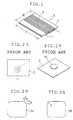
- a transponder in accordance with a second embodiment of the present inventionhas two plate antennas each comprising a magnetic core composed of layered metallic thin plates around which a conductor coil is wound, and an air-core antenna composed of a spirally wound conductor.
- An antenna for a transponder in accordance with a third embodiment of the present inventioncomprises a plate magnetic core composed of a composite material of magnetically soft flakes and a synthetic resin, and a coil wound around such a magnetic core.
- Such an antenna for a transponderis thin and flexible and has a decreased high-frequency loss, because the magnetic core is composed of a composite material of a magnetically soft flake and a synthetic resin.
- the magnetic fluxflows parallel to the transponder plate or plane.
- the magnetic fluxis nearly not affected by a coin or an aluminum foil or similar material overlapping the transponder plate.
- a transponder in accordance with a fourth embodiment of the present inventioncomprises two plate antennas in accordance with the third embodiment set forth above, and an air-core antenna composed of a spirally wound conductor.
- FIG. 1is a perspective view illustrating a prefered feature of an antenna 3 in accordance with the first embodiment of the present invention.
- This antenna 3comprises a magnetic core 4 composed of layered metallic thin plates, and a coil 5 wound thereon.
- Preferred materials for the metallic thin platesare magnetically soft materials, and in particular, of having excellent magnetic properties and a large specific resistance, i.e. a large, resistivity.
- Examples of such materialsinclude amorphous magnetic materials, such as METAGLAS 2714A (Co-Fe-Ni-B-Si type), 2605S2 (Fe-B-Si type), 2605SC (Fe-B-Si-C type) and 2876MB (Fe-Ni-Mo-B type) made by Allied Signal; iron-nickel alloys, such as JIS 2531 PB PC; silicon steels, such as JIS 2553 Z6H and RC6HL G09 S09; and the like.
- Co-Fe-Ni-B-Si-type amorphous magnetic materialis more preferred, and the preferable thickness of the metallic thin plates range from 20 to 50 ⁇ m.
- the number of the layered metallic thin platesis preferably 3 to 16. Although only metallic thin plates can be layered without inserting other material, metallic thin plates which are insulated by coating or oxidizing their surfaces also may be layered. Further, in order to secure the insulation between the metallic thin plates, an insulating material, such as paper and polymeric films may be inserted between the metallic thin plates in the layering.
- the ratio B/A of the side length B to the side length A in the magnetic core 4 composed of layered metallic thin platesis 1 or, preferably less than 1 and, more preferably 0.4 to 1.0, and even more preferably 0.5 to 0.9.
- the conductor wound as the coil 5is preferably 100 to 200 ⁇ m in diameter.
- the conductoris wound around the magnetic core 4 in the direction parallel to its long side.
- the prefered thickness of the antenna 3 after the coil is wound around itis 0.4 mm or less, and more prefered 0.3 mm or less.
- the cross-section of the conductor of the coil 5is typically circular, and is preferably rectangular for the more compact coil.
- Suitable materials for the conductorare pure copper for general use, chromium copper for a use requiring particular strength for higher vibration resistance, highly conductive silver for more compact size, corrosion resistive gold for the use requiring high reliability, and aluminum for lighter weight.
- the magnetic core of the antenna in accordance with the present inventionis flexible to prevent breakage due to bending. Further, because the antenna is thin and the coil axis can be set to be parallel to the transponder plate, its characteristics are nearly not affected or deteriorated when a coin or aluminum foil or other ferrous or non-ferrous metal materials overlaps with the transponder. Thus, the antenna has a small loss at high frequencies.
- the term loss used in the specificationincludes eddy current loss.
- the transponder 12 shown in FIGs. 5A and 5Bmay be provided with a magnetic recording layer, such as a magnetic stripe 13, at the surface, and the antenna 14 in accordance with the present invention.
- the transpondercan be used in both the contact and non-contact states. Any printing 15 may be applied on the surface without magnetic recording for the visual judgement. Any embossment can be formed at the sections other than the antenna, circuit and magnetic recording layer for clearer printing and improving the durability against rewrite and wear.
- the transponder 12has a circuit chip 16.
- Examples of magnetically soft materials used for the flakes of a composite material suitable as a magnetic core for the antenna of the transponder in accordance with a third embodiment of the present inventioninclude pure iron, silicon steel, permalloys (Fe-Ni alloy), iron/cobalt amorphous alloys, and in particular, cobalt amorphous alloys (Co-Fe-Ni-B-Si).
- Amorphous alloyshave excellent highfrequency characteristics, and are readily formed to flakes by striking to quench the molten drops from the molten alloy flow on the copper surface cooled with water.
- the flexibility of the composite materialincreases and the shaping characteristics improve with the increased synthetic resin content in the composite material.
- the resin contentis too small, the strength of the composite material decreases.
- an excessive synthetic resin contentcauses a decrease in permeability. Accordingly, the prefered amount of the synthetic resin is 3 to 50 weight%, and more preferably 10 to 40 weight% of the composite material.
- Usable molding methodsinclude injection molding, compression molding, rolling, and doctor blade shaping.
- a composite material having excellent magnetic characteristicscan be obtained by compression molding, rolling or doctor blade shaping, since the flake plane is oriented to the plane of the composite material.
- the size suitable to carrying out such a methodis 0.3 to 2 mm in thickness, 100 mm or less in width and length, and in particular, 0.3 to 1 mm in thickness, 10 to 25 mm in width, and 60 to 80 mm in length.
- the diameter of the conductorpreferably ranges from 100 to 200 ⁇ m.
- the coilis wound perpendicular to the longer side of the antenna, in other words, the coil axis is parallel to the longer side.
- the antenna for the transponder in accordance with the present inventionexhibits excellent effects in that the antenna is thin and flexible, the loss is low at high frequencies over 100 kHz, and the antenna is less affected by a coin or aluminum foil package or other ferrous or non-ferrous metal materials.
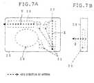
- the transponderWhen the transponder is used as an ID card or a communter pass to be carried in the pocket and effective on an automatic wicket, there is no correlation between the direction of the interrogator antenna and the direction of the transponder defined. Thus, the transponder must respond to radio waves from all the directions.
- a transponderwhich has two plate antennas crossing each other, can respond to the direction parallel to the plate, but cannot respond to the direction perpendicular to the plate.
- the 7A and 7Bcan respond to waves from all the directions, regardless of the direction of the transponder; the antenna 27 responds to radio waves in the X direction, the antenna 26 responds to radio waves in the Y direction, and the air-core antenna (coil) 29 responds to radio waves in the Z direction.
- a sheet composed of Allied Signal METAGLAS 2714A having a width of 50 mm and a thickness 25 ⁇ mwas used as a magnetic core material.
- the sheetwas cut into a size shown in Table 1, was heated at 250°C for 10 min. in air, and quenched.
- a magnetic corewas produced by layering a few sheets so as to reach the thickness shown in Table 1.
- An insulation conductor having a diameter of 0.15 mmwas wound around the magnetic core so that the inductance L of the coil is approximately 3 mH. The conductor was wound in the direction parallel to the longer side of the magnetic core in Examples, and in the direction parallel to the shorter side of the magnetic core in Comparative Examples.
- Table 1evidently demonstrates that the resistance significantly decreases by winding the coil in the direction parallel to the longer side of the magnetic core.
- the magnetic core size perpendicluar to coil axisis represented by A
- the magnetic core size parallel to the coil axisis represented by B
- the magnetic core size perpendicular to the plane ABis represented by C.
- an antennacomposed of an air-core coil of which a conductor having a diameter of 0.016 mm was wound by 400 turns.
- a magnetic core materialwas prepared by mixing Co-type amorphous metal flakes having an average thickness of 5 ⁇ m and an average diameter of 500 ⁇ m with an epoxy resin in an amount of 20% (the rate of the resin to the total of the flake and resin) and by compression-molding at 160°C and 200 kg/cm 2 .
- the magnetic core materialwas cut into cut sheets having a thickness of 0.6 mm, a width of 25 mm, and a length of 80 mm.
- a conductor having a diameter of 0.15 mmwas wound in the direction parallel to the cut sheet so that L is 3 mH.
- a magnetic core materialwas prepared by mixing Co-type amorphous metal flakes having an average thickness of 5 ⁇ m and an average diameter of 500 ⁇ m with an epoxy resin in an amount of 30% (the rate of the resin to the total of the flake and resin) and by compression-molding at 160°C and 200 kg/cm 2 .
- the magnetic core materialwas cut into cut sheets having a thickness of 0.6 mm, a width of 25 mm, and a length of 80 mm.
- a conductor having a diameter of 0.15 mmwas wound in the direction parallel to the cut sheet so that L is 3 mH.
- a magnetic core materialwas prepared by mixing Co-type amorphous metal flakes having an average thickness of 10 ⁇ m and an average diameter of 500 ⁇ m with an epoxy resin in an amount of 20% (the rate of the resin to the total of the flake and resin) and by compression-molding at 160°C and 200 kg/cm 2 .
- the magnetic core materialwas cut into cut sheets having a thickness of 0.6 mm, a width of 25 mm, and a length of 80 mm.
- a conductor having a diameter of 0.15 mmwas wound in the direction parallel to the cut sheet so that L is 3 mH.
- a magnetic core materialwas prepared by mixing Co-type amorphous metal flakes having an average thickness of 5 ⁇ m and an average diameter of 500 ⁇ m with a mixture of an urethan resin and an epoxy resin in an amount of 20% (the rate of the resin mixture to the total of the flake and resin mixture) and by compression-molding at 160°C and 200 kg/cm 2 .
- the magnetic core materialwas cut into cut sheets having a thickness of 0.6 mm, a width of 25 mm, and a length of 80 mm.
- a conductor having a diameter of 0.15 mmwas wound in the direction parallel to the cut sheet so that L is 3 mH.
- a magnetic core materialwas prepared by cutting Allied Chemical METAGLAS 2714A into a rectangular pieces having a width of 25 mm and a length of 50 mm. A magnetic core having a thickness of 0.3 mm was produced by layering 12 pieces. A conductor having a diameter of 0.15 mm was wound in the direction parallel to the cut sheet so that L is 3 mH.
Landscapes
- Engineering & Computer Science (AREA)
- Computer Hardware Design (AREA)
- Microelectronics & Electronic Packaging (AREA)
- Physics & Mathematics (AREA)
- General Physics & Mathematics (AREA)
- Theoretical Computer Science (AREA)
- Computer Networks & Wireless Communication (AREA)
- Chemical & Material Sciences (AREA)
- Dispersion Chemistry (AREA)
- Power Engineering (AREA)
- Soft Magnetic Materials (AREA)
- Near-Field Transmission Systems (AREA)
Description

| Frequency (kHz) | Example A Core with Cut Corner (Ω) | Example B Core with Rounded Corner (Ω) | Example C Core without Corner Treatment (Ω) |
| 30 | 2.1 | 2.2 | 2.7 |
| 40 | 3.7 | 3.8 | 4.4 |
| 50 | 3.5 | 3.7 | 4.8 |
| 60 | 5.7 | 6.0 | 7.8 |
| 80 | 13.9 | 14.5 | 17.6 |
| 100 | 23.7 | 24.7 | 29.4 |
| 120 | 37.7 | 39.2 | 46.6 |
| 150 | 54.1 | 56 | 65.8 |
| 200 | 108.6 | 112.3 | 134.1 |
| Example Coil with Core Core | Comparative Example Air-core Coil Conductor | |
| Frequency (kHz) | Diameter 0.16 mm Number of Turns 180 (Ω) | Diameter 0.16 mm Number of Turns 400 (Ω) |
| 30 | 6.2 | 20.0 |
| 40 | 8.8 | 23.3 |
| 50 | 11.6 | 26.4 |
| 60 | 14.8 | 29.5 |
| 80 | 21.7 | 35.3 |
| 100 | 29.9 | 41.2 |
| 120 | 39.0 | 47.1 |
| 150 | 55.6 | 56.3 |
| 200 | 70.0 | 73.1 |

Claims (27)
- An antenna (3; 6, 7, 9; 14; 26, 27, 29) for a transponder (8; 12; 28)comprising a flat rectangular magnetic core (4) composed of a composite materialand a coil (5) wound on said magnetic core (4), characterized in that said coil(5) is wound parallel to the longer side of the magnetic core, and in that thecorners of said magnetic core (4) are cut (a) or rounded (b).
- An antenna for a responder according to claim 1, wherein the compositematerial comprises layered rectangular metallic thin plates.
- An antenna for a transponder according to claim 2, wherein the thinplates comprise an amorphous magnetic material.
- An antenna for a transponder according to one or more of the claims 2to 3, wherein the thickness of the thin plates is 20 to 50 µm.
- An antenna for a transponder according to one or more of the claims 2to 4, wherein the number of the layered thin plates is 3 to 16.
- An antenna for a transponder according to one or more of claims 2 to5, wherein the thin plates which are insulated by oxidizing their surfaces arelayered.
- An antenna for a transponder according to one or more of the claims 2to 6, wherein the ratio B/A of the lengths of the shorter side B to the longer sideA of the magnetic core (4) is 0.4 to 1.0.
- An antenna for a transponder according to one or more of the claims 2to 7, wherein the thickness of the antenna is 0.4 mm or less.
- An antenna for a transponder according to claim 1, wherein the compositematerial is composed of magnetically soft flakes and a synthetic resin.
- An antenna for a transponder according to claim 9, wherein themagnetically soft material composing said flakes is selected from pure iron,silicon steel, a permalloy (an Fe-Ni alloy) and an iron/cobalt amorphous alloy.
- An antenna for a transponder according to claim 10, wherein themagnetically soft material composing said flakes is a cobalt amorphous alloy(Co-Fe-Ni-B-Si).
- An antenna for a transponder according to one or more of claims9 to 11, wherein said flake has a thickness of 30 µm or less and a diameter of50 to 2,000 µm.
- An antenna for a transponder according to claim 12, wherein saidflakes have a thickness of 10 µm or less and a diameter of 100 to 1,000 µm.
- An antenna for a transponder according to one or more of claims9 to 13, wherein said synthetic resin is selected from the group consisting of thethermoset resins, e.g. epoxy resins, phenol resins, urea resins, unsaturatedpolyester resins, diacrylphthalate resins, melamine resins, silicone resins, andpolyurethane resins; and thermoplastic resins, e.g. polyethylene resins,polypropylene resins, vinyl chloride resins, fluoroplastics, methacrylate resins,polystyrene resins, AS resins, ABS resins, ABA resins, polycarbonate resins,polyacetal resins, and polyimide resins.
- An antenna for a transponder according to one or more of claims9 to 14, wherein the amount of said synthetic resin in the composite material is3 to 50 weight%.
- An antenna for a transponder according to one or more of claims9 to 15, wherein said flakes comprise a cobalt base amorphous alloy, whereassaid synthetic resin is an epoxy resin, and the amount of said synthetic resin inthe composite material is 10 to 40 weight%.
- An antenna for a transponder according to one or more of claims9 to 15, wherein said magnetic core has a thickness of 0.3 to 2 mm, and awidth and length of 100 mm or less, respectively.
- An antenna for a transponder according to claim 17, wherein saidmagnetic core has a thickness of 0.3 to 1 mm, a width of 10 to 25 mm and alength of 60 to 80 mm.
- An antenna for a transponder according to one or more of thepreceding claims, wherein the diameter of the coil conductor is 100 to 200 µm.
- An antenna for a transponder according to one or more of thepreceding claims, wherein said antenna for a transponder is suitable to carry asan ID card, a commuter pass or a coupon ticket which operates at a frequencyover 100 kHz with said plate magnetic core and at a frequency between 40 kHzand 200 kHz with said magnetic core comprised of layered thin plates.
- A plate transponder (8; 28) comprising two plate antennas (6, 7;26, 27) composed of a wound conductor on a magnetic core (4) as defined inone or more of the preceding claims and an air-core antenna (9; 29) composedof a spirally wound conductor.
- A transponder (8; 28) according to claim 21, wherein axes of saidthree antennas (6, 7, 9; 26, 27, 29) are oriented to three directions perpendicularto each other.
- A transponder (8; 28) according to claim 21 or 22, wherein saidtwo plate antennas (6, 7; 26, 27) are provided in the plate transponder (8; 28) so that the axes (X, Y) of said two antennas or coils are perpendicular to eachother, and said air-core antenna (9; 29) composed of the spirally wound conductoris provided in the plate transponder (8; 28) so that the axis (Z) thereof isperpendicular to the transponder plate (8; 28).
- A transponder (12) according to one or more of the claims 21 to23, wherein a magnetic recording layer such as a magnetic strip (13) is providedon the surface of the transponder (12), and antennas (14) are provided insidethe transponder (12).
- A transponder (12) according to one or more of the claims 21 to24, wherein a printing is provided on the surface.
- A transponder according to one or more of the claims 21 to 25,wherein embossment is formed on the sections other than said antennas (14),circuit, and magnetic recording layer.
- A transponder according to one or more of the claims 21 to 26,wherein said transponder (8; 12; 28) is suitable to be carried as an ID card, acommuter pass or a coupon ticket which operates at a frequency of 40 to 200kHz.
Applications Claiming Priority (6)
| Application Number | Priority Date | Filing Date | Title |
|---|---|---|---|
| JP213353/95 | 1995-08-22 | ||
| JP21335395 | 1995-08-22 | ||
| JP176543/96 | 1996-07-05 | ||
| JP176544/96 | 1996-07-05 | ||
| JP17654396 | 1996-07-05 | ||
| JP8176544AJPH1022722A (en) | 1996-07-05 | 1996-07-05 | Antenna for transponder using a composite material and transponder |
Publications (2)
| Publication Number | Publication Date |
|---|---|
| EP0762535A1 EP0762535A1 (en) | 1997-03-12 |
| EP0762535B1true EP0762535B1 (en) | 1998-11-04 |
Family
ID=27324275
Family Applications (1)
| Application Number | Title | Priority Date | Filing Date |
|---|---|---|---|
| EP96113479AExpired - LifetimeEP0762535B1 (en) | 1995-08-22 | 1996-08-22 | Antenna for transponder and transponder |
Country Status (4)
| Country | Link |
|---|---|
| US (1) | US6930646B2 (en) |
| EP (1) | EP0762535B1 (en) |
| KR (1) | KR100459839B1 (en) |
| DE (1) | DE69600910T2 (en) |
Cited By (11)
| Publication number | Priority date | Publication date | Assignee | Title |
|---|---|---|---|---|
| US6154137A (en) | 1998-06-08 | 2000-11-28 | 3M Innovative Properties Company | Identification tag with enhanced security |
| US6232870B1 (en) | 1998-08-14 | 2001-05-15 | 3M Innovative Properties Company | Applications for radio frequency identification systems |
| US6335686B1 (en) | 1998-08-14 | 2002-01-01 | 3M Innovative Properties Company | Application for a radio frequency identification system |
| US6424262B2 (en) | 1998-08-14 | 2002-07-23 | 3M Innovative Properties Company | Applications for radio frequency identification systems |
| DE10325909A1 (en)* | 2003-06-05 | 2005-01-05 | Deutsche Post Ag | Method and device for securing objects |
| US7044373B1 (en) | 1998-08-14 | 2006-05-16 | 3M Innovative Properties Company | Radio frequency identification systems applications |
| US7508350B2 (en) | 2003-01-23 | 2009-03-24 | Vacuumschmelze Gmbh & Co. Kg | Antenna core |
| US7570223B2 (en) | 2003-01-23 | 2009-08-04 | Vacuumschmelze Gmbh & Co. Kg | Antenna core and method for production of an antenna core |
| US7978078B2 (en) | 2001-12-21 | 2011-07-12 | Sensormatic Electronics, LLC | Magnetic core transceiver for electronic article surveillance marker detection |
| DE102005015006B4 (en)* | 2005-04-01 | 2013-12-05 | Vacuumschmelze Gmbh & Co. Kg | magnetic core |
| US20220285067A1 (en)* | 2017-02-03 | 2022-09-08 | Taiyo Yuden Co., Ltd. | Wire-wound coil element |
Families Citing this family (44)
| Publication number | Priority date | Publication date | Assignee | Title |
|---|---|---|---|---|
| DE19718423A1 (en)* | 1997-04-30 | 1998-11-05 | Siemens Ag | Portable signal receiver |
| FR2777141B1 (en)* | 1998-04-06 | 2000-06-09 | Gemplus Card Int | TRANSPONDER |
| CH693394A5 (en)* | 1999-05-07 | 2003-07-15 | Njc Innovations | chip card comprising an antenna. |
| FR2808943B1 (en)* | 2000-05-12 | 2004-10-01 | Valeo Electronique | IDENTIFIER FOR "HANDS-FREE ACCESS AND STARTING" SYSTEM WITH A TRANSMITTER AND / OR RECEIVER COIL PLACED IN THE THICKNESS OF THE SUBSTRATE |
| FR2812780A1 (en)* | 2000-08-04 | 2002-02-08 | Delphi Tech Inc | REMOTE CONTROL SYSTEM FOR MOTOR VEHICLES WITH AN IMPROVED RECEPTION ANTENNA |
| EP1195714A1 (en)* | 2000-10-04 | 2002-04-10 | Sokymat S.A. | Transponder unit |
| US6563474B2 (en)* | 2000-12-21 | 2003-05-13 | Lear Corporation | Remote access device having multiple inductive coil antenna |
| US7588185B2 (en) | 2001-06-07 | 2009-09-15 | 3M Innovative Properties Company | RFID data collection and use |
| DE10145413A1 (en)* | 2001-09-14 | 2005-06-09 | Focke Gmbh & Co. Kg | Method for identifying items and item with electronic data carrier |
| EP1439608A4 (en)* | 2001-09-28 | 2008-02-06 | Mitsubishi Materials Corp | Antenna coil and rfid-use tag using it, transponder-use antenna |
| DE10151889A1 (en)* | 2001-10-24 | 2003-05-08 | Convenience Food Sys Wallau | packaging machine |
| DE10160452C2 (en) | 2001-12-04 | 2003-11-06 | Balluff Gmbh | Code carrier device |
| JP3896965B2 (en)* | 2002-01-17 | 2007-03-22 | 三菱マテリアル株式会社 | Reader / writer antenna and reader / writer equipped with the antenna |
| JP2003283231A (en)* | 2002-03-26 | 2003-10-03 | Aisin Seiki Co Ltd | Antenna and manufacturing method thereof |
| JP3780995B2 (en)* | 2002-10-03 | 2006-05-31 | カシオ計算機株式会社 | Antenna and antenna manufacturing method |
| US7091858B2 (en)* | 2003-01-14 | 2006-08-15 | Sensormatic Electronics Corporation | Wide exit electronic article surveillance antenna system |
| US7019651B2 (en)* | 2003-06-16 | 2006-03-28 | Sensormatic Electronics Corporation | EAS and RFID systems incorporating field canceling core antennas |
| US7167140B2 (en)* | 2003-07-02 | 2007-01-23 | Nec Tokin Corporation | Coil antenna |
| US7023395B2 (en)* | 2003-08-05 | 2006-04-04 | Matsushita Electric Industrial Co., Ltd. | Antenna and communication system using the same |
| DE102004002881B4 (en)* | 2004-01-20 | 2009-05-07 | Trw Airbag Systems Gmbh | Gas generator, gas bag module and method for their detection |
| DE102004023815A1 (en)* | 2004-05-13 | 2005-12-08 | Vacuumschmelze Gmbh & Co. Kg | Antenna arrangement and use of the antenna arrangement |
| FR2884681B1 (en)* | 2005-04-15 | 2007-06-22 | St Microelectronics Sa | ANTENNA FOR ELECTRONIC LABEL |
| US8072387B2 (en)* | 2005-07-07 | 2011-12-06 | Toda Kogyo Corporation | Magnetic antenna and board mounted with the same |
| JP2007041666A (en)* | 2005-08-01 | 2007-02-15 | Ricoh Co Ltd | RFID tag and manufacturing method thereof |
| US7503491B2 (en)* | 2005-10-29 | 2009-03-17 | Magnex Corporation | RFID chip and antenna with improved range |
| DE102006042349B4 (en)* | 2006-09-08 | 2010-05-20 | Vacuumschmelze Gmbh & Co. Kg | Method for producing a magnet arrangement with a flat magnetic core and such magnet arrangement |
| TW200826366A (en)* | 2006-11-02 | 2008-06-16 | Murata Manufacturing Co | Antenna coil and antenna unit |
| JP2008153925A (en)* | 2006-12-18 | 2008-07-03 | Alps Electric Co Ltd | Antenna sheet and its manufacturing method |
| JP5024366B2 (en)* | 2007-03-09 | 2012-09-12 | 株式会社村田製作所 | Antenna coil and antenna device |
| JP2009005171A (en)* | 2007-06-22 | 2009-01-08 | Toshiba Corp | Wireless device |
| US9136600B2 (en) | 2010-09-30 | 2015-09-15 | Murata Manufacturing Co., Ltd. | Antenna |
| EP2317337A1 (en)* | 2009-11-03 | 2011-05-04 | Gemalto SA | Contactless transfer system for personal data |
| US9190711B2 (en)* | 2010-07-28 | 2015-11-17 | Panasonic Intellectual Property Management Co., Ltd. | Antenna device and communication apparatus including the same |
| CN103633421B (en)* | 2012-08-27 | 2016-07-06 | Tdk株式会社 | Antenna assembly |
| JP6287271B2 (en) | 2014-01-31 | 2018-03-07 | 株式会社村田製作所 | 3-axis antenna |
| US20160172087A1 (en)* | 2014-12-11 | 2016-06-16 | Metglas, Inc. | Fe-Si-B-C-BASED AMORPHOUS ALLOY RIBBON AND TRANSFORMER CORE FORMED THEREBY |
| WO2016144122A1 (en)* | 2015-03-10 | 2016-09-15 | 주식회사 아모텍 | Antenna module and portable device having same |
| US10461398B2 (en)* | 2015-04-03 | 2019-10-29 | Fit Pay, Inc. | Accordion antenna structure with simplified construction |
| KR102198528B1 (en)* | 2015-05-19 | 2021-01-06 | 삼성전기주식회사 | Coil electronic component and manufacturing method thereof |
| KR102516883B1 (en) | 2016-08-04 | 2023-04-03 | 삼성전자주식회사 | Electronic device with shielding structure |
| SK289113B6 (en)* | 2016-09-19 | 2023-09-13 | Logomotion, S.R.O | Antenna with core, especially miniature RFID and/or NFC antenna and its mode of production |
| KR102541839B1 (en)* | 2018-07-31 | 2023-06-09 | 삼성전자 주식회사 | Electronic device having a plurality of stacked coil antennas |
| WO2020044203A1 (en)* | 2018-08-31 | 2020-03-05 | 3M Innovative Properties Company | Coil and method of making same |
| EP4381531B1 (en)* | 2021-08-03 | 2025-04-30 | Premo, SL | Surface mounting inductive coiled component for mounting on printed circuit boards |
Family Cites Families (22)
| Publication number | Priority date | Publication date | Assignee | Title |
|---|---|---|---|---|
| US3031667A (en)* | 1959-11-03 | 1962-04-24 | Motorola Inc | Magnetic antenna apparatus |
| US3495264A (en)* | 1966-12-09 | 1970-02-10 | Continental Electronics Mfg | Loop antenna comprising plural helical coils on closed magnetic core |
| US3683389A (en)* | 1971-01-20 | 1972-08-08 | Corning Glass Works | Omnidirectional loop antenna array |
| US3898565A (en)* | 1971-03-05 | 1975-08-05 | Mishima Kosan Co Ltd | Magnetic wave communication system |
| JPS5330976B1 (en)* | 1971-07-22 | 1978-08-30 | ||
| JPS5511669A (en)* | 1978-07-12 | 1980-01-26 | Tdk Corp | Magnetic core for antenna |
| JPS56134810A (en) | 1980-03-26 | 1981-10-21 | Hitachi Ltd | Class "b" push-pull output circuit |
| JPS5894204A (en)* | 1981-11-30 | 1983-06-04 | Seiko Instr & Electronics Ltd | Loop antenna containing magnetic core |
| JPS5894204U (en)* | 1982-05-17 | 1983-06-25 | ヤマギワ株式会社 | spot light |
| JPS60233904A (en)* | 1984-05-04 | 1985-11-20 | Matsushita Electric Ind Co Ltd | Antenna system |
| US4937586A (en)* | 1986-09-22 | 1990-06-26 | Stevens John K | Radio broadcast communication systems with multiple loop antennas |
| US4879570A (en)* | 1987-03-24 | 1989-11-07 | Nippon Antenna Co., Ltd. | Broadcasting wave reception antenna |
| JP2611994B2 (en)* | 1987-07-23 | 1997-05-21 | 日立金属株式会社 | Fe-based alloy powder and method for producing the same |
| JPS6454906A (en) | 1987-08-26 | 1989-03-02 | Yahata Denki Sangyo Kk | Reception antenna |
| DE8815967U1 (en)* | 1988-05-27 | 1989-09-21 | Junghans Uhren GmbH, 7230 Schramberg | Antenna for a small radio clock |
| JPH0364105A (en) | 1989-07-31 | 1991-03-19 | Amano Corp | Antenna device for electronic cards |
| JPH0494502A (en) | 1990-08-10 | 1992-03-26 | Furukawa Electric Co Ltd:The | High magnetic permeability material and its manufacturing method, and manufacturing method of high magnetic permeability alloy powder |
| EP0554486B1 (en)* | 1992-02-05 | 1998-07-22 | Texas Instruments Deutschland Gmbh | Method of producing a flexible HF antenna |
| EP0554581B1 (en)* | 1992-02-05 | 1997-05-28 | Texas Instruments Incorporated | Method for producing a flat flexible antenna core for a chip transponder to be incorporated in a badge or similar object, and a thus produced antenna core |
| GB9305085D0 (en) | 1993-03-12 | 1993-04-28 | Esselte Meto Int Gmbh | Electronic article surveillance system with enhanced geometric arrangement |
| JPH07221533A (en)* | 1994-02-01 | 1995-08-18 | Hitachi Metals Ltd | Antenna |
| JP3891448B2 (en)* | 1994-04-11 | 2007-03-14 | 日立金属株式会社 | Thin antenna and card using the same |
- 1996
- 1996-08-17KRKR1019960034104Apatent/KR100459839B1/ennot_activeExpired - Fee Related
- 1996-08-22DEDE69600910Tpatent/DE69600910T2/ennot_activeExpired - Lifetime
- 1996-08-22EPEP96113479Apatent/EP0762535B1/ennot_activeExpired - Lifetime
- 1996-08-22USUS08/701,457patent/US6930646B2/ennot_activeExpired - Fee Related
Cited By (20)
| Publication number | Priority date | Publication date | Assignee | Title |
|---|---|---|---|---|
| US6646554B1 (en) | 1998-06-08 | 2003-11-11 | 3M Innovative Properties Company | Identification tag with enhanced security |
| US6154137A (en) | 1998-06-08 | 2000-11-28 | 3M Innovative Properties Company | Identification tag with enhanced security |
| US7044373B1 (en) | 1998-08-14 | 2006-05-16 | 3M Innovative Properties Company | Radio frequency identification systems applications |
| US7270268B2 (en) | 1998-08-14 | 2007-09-18 | 3M Innovative Properties Company | Radio frequency identification systems applications |
| US6448886B2 (en) | 1998-08-14 | 2002-09-10 | 3M Innovative Properties Company | Application for radio frequency identification systems |
| US6486780B1 (en) | 1998-08-14 | 2002-11-26 | 3M Innovative Properties Company | Applications for radio frequency identification systems |
| US6600420B2 (en) | 1998-08-14 | 2003-07-29 | 3M Innovative Properties Company | Application for a radio frequency identification system |
| US6335686B1 (en) | 1998-08-14 | 2002-01-01 | 3M Innovative Properties Company | Application for a radio frequency identification system |
| US6768419B2 (en) | 1998-08-14 | 2004-07-27 | 3M Innovative Properties Company | Applications for radio frequency identification systems |
| US8006902B2 (en) | 1998-08-14 | 2011-08-30 | 3M Innovative Properties Company | Radio frequency identification systems applications |
| US6232870B1 (en) | 1998-08-14 | 2001-05-15 | 3M Innovative Properties Company | Applications for radio frequency identification systems |
| US6424262B2 (en) | 1998-08-14 | 2002-07-23 | 3M Innovative Properties Company | Applications for radio frequency identification systems |
| US7978078B2 (en) | 2001-12-21 | 2011-07-12 | Sensormatic Electronics, LLC | Magnetic core transceiver for electronic article surveillance marker detection |
| US7508350B2 (en) | 2003-01-23 | 2009-03-24 | Vacuumschmelze Gmbh & Co. Kg | Antenna core |
| US7570223B2 (en) | 2003-01-23 | 2009-08-04 | Vacuumschmelze Gmbh & Co. Kg | Antenna core and method for production of an antenna core |
| US7518509B2 (en) | 2003-06-05 | 2009-04-14 | Deutsche Post Ag | Method and device for securing objects |
| DE10325909A1 (en)* | 2003-06-05 | 2005-01-05 | Deutsche Post Ag | Method and device for securing objects |
| DE102005015006B4 (en)* | 2005-04-01 | 2013-12-05 | Vacuumschmelze Gmbh & Co. Kg | magnetic core |
| US20220285067A1 (en)* | 2017-02-03 | 2022-09-08 | Taiyo Yuden Co., Ltd. | Wire-wound coil element |
| US11901106B2 (en)* | 2017-02-03 | 2024-02-13 | Taiyo Yuden Co., Ltd. | Wire-wound coil element |
Also Published As
| Publication number | Publication date |
|---|---|
| DE69600910D1 (en) | 1998-12-10 |
| US20030107523A1 (en) | 2003-06-12 |
| KR100459839B1 (en) | 2005-02-07 |
| US6930646B2 (en) | 2005-08-16 |
| EP0762535A1 (en) | 1997-03-12 |
| KR980012707A (en) | 1998-04-30 |
| DE69600910T2 (en) | 1999-07-29 |
Similar Documents
| Publication | Publication Date | Title |
|---|---|---|
| EP0762535B1 (en) | Antenna for transponder and transponder | |
| TWI258710B (en) | Antenna for reader/recorder and reader/recorder having the antenna | |
| EP1640893B1 (en) | Antenna for RFID tag | |
| TW589765B (en) | Antenna coil and RFID, transponder antenna using the same | |
| US5567537A (en) | Magnetic core element for antenna, thin-film antenna, and card equipped with thin-film antenna | |
| KR101707883B1 (en) | Hybrid Type Magnetic Field Shield Sheet and Antenna Module Using the Same | |
| JP4265114B2 (en) | Antenna coil for tags | |
| US6840440B2 (en) | Identifying system of overlapped tag | |
| CN1855623B (en) | Absorber for radio-frequency identificating antenna, preparation method thereof and radio-frequency identificating antenna using the same | |
| US20090159657A1 (en) | Contactless integrated circuit card system | |
| KR101810248B1 (en) | Composite rf tag and tool provided with the composite rf tag | |
| KR19990029264A (en) | Anti-theft Tag | |
| EP1901393A1 (en) | Antenna device | |
| EP1229482B1 (en) | Antenna for card reader | |
| TW201006034A (en) | Composite magnetic antenna and RF tag, metal part and metal instrument attached with the composite magnetic antenna or RF tag | |
| JP3362607B2 (en) | Transponder antenna and transponder | |
| JP2002373319A (en) | Non-contact data carrier package, and antenna magnetic core for non-contact data carrier used therefor | |
| JP2002208814A (en) | Communication device, mounting structure thereof, and information reading method of communication device | |
| JP2004038552A (en) | Case for electronic equipment and electronic equipment provided with the case | |
| JP4048360B2 (en) | Reader / writer antenna and reader / writer equipped with the antenna | |
| WO1997042598A1 (en) | Smart card formed with two joined sheets | |
| JP2005176390A (en) | Antenna for transponder | |
| KR100242265B1 (en) | Novel Thrombin Inhibitors with Arylalkylsulfonyl Structures |
Legal Events
| Date | Code | Title | Description |
|---|---|---|---|
| PUAI | Public reference made under article 153(3) epc to a published international application that has entered the european phase | Free format text:ORIGINAL CODE: 0009012 | |
| AK | Designated contracting states | Kind code of ref document:A1 Designated state(s):DE FR GB | |
| 17P | Request for examination filed | Effective date:19970227 | |
| 17Q | First examination report despatched | Effective date:19970603 | |
| GRAG | Despatch of communication of intention to grant | Free format text:ORIGINAL CODE: EPIDOS AGRA | |
| GRAG | Despatch of communication of intention to grant | Free format text:ORIGINAL CODE: EPIDOS AGRA | |
| GRAH | Despatch of communication of intention to grant a patent | Free format text:ORIGINAL CODE: EPIDOS IGRA | |
| GRAH | Despatch of communication of intention to grant a patent | Free format text:ORIGINAL CODE: EPIDOS IGRA | |
| GRAA | (expected) grant | Free format text:ORIGINAL CODE: 0009210 | |
| AK | Designated contracting states | Kind code of ref document:B1 Designated state(s):DE FR GB | |
| REF | Corresponds to: | Ref document number:69600910 Country of ref document:DE Date of ref document:19981210 | |
| ET | Fr: translation filed | ||
| PLBE | No opposition filed within time limit | Free format text:ORIGINAL CODE: 0009261 | |
| STAA | Information on the status of an ep patent application or granted ep patent | Free format text:STATUS: NO OPPOSITION FILED WITHIN TIME LIMIT | |
| 26N | No opposition filed | ||
| REG | Reference to a national code | Ref country code:GB Ref legal event code:IF02 | |
| PGFP | Annual fee paid to national office [announced via postgrant information from national office to epo] | Ref country code:GB Payment date:20090827 Year of fee payment:14 Ref country code:DE Payment date:20090821 Year of fee payment:14 | |
| GBPC | Gb: european patent ceased through non-payment of renewal fee | Effective date:20100822 | |
| REG | Reference to a national code | Ref country code:FR Ref legal event code:ST Effective date:20110502 | |
| REG | Reference to a national code | Ref country code:DE Ref legal event code:R119 Ref document number:69600910 Country of ref document:DE Effective date:20110301 | |
| PG25 | Lapsed in a contracting state [announced via postgrant information from national office to epo] | Ref country code:DE Free format text:LAPSE BECAUSE OF NON-PAYMENT OF DUE FEES Effective date:20110301 Ref country code:FR Free format text:LAPSE BECAUSE OF NON-PAYMENT OF DUE FEES Effective date:20100831 | |
| PG25 | Lapsed in a contracting state [announced via postgrant information from national office to epo] | Ref country code:GB Free format text:LAPSE BECAUSE OF NON-PAYMENT OF DUE FEES Effective date:20100822 | |
| PGFP | Annual fee paid to national office [announced via postgrant information from national office to epo] | Ref country code:FR Payment date:20090914 Year of fee payment:14 |