EP0760547B1 - Battery pack with a lithium ion secondary battery - Google Patents
Battery pack with a lithium ion secondary batteryDownload PDFInfo
- Publication number
- EP0760547B1 EP0760547B1EP96113497AEP96113497AEP0760547B1EP 0760547 B1EP0760547 B1EP 0760547B1EP 96113497 AEP96113497 AEP 96113497AEP 96113497 AEP96113497 AEP 96113497AEP 0760547 B1EP0760547 B1EP 0760547B1
- Authority
- EP
- European Patent Office
- Prior art keywords
- battery
- voltage
- lithium ion
- circuit
- battery pack
- Prior art date
- Legal status (The legal status is an assumption and is not a legal conclusion. Google has not performed a legal analysis and makes no representation as to the accuracy of the status listed.)
- Expired - Lifetime
Links
- HBBGRARXTFLTSG-UHFFFAOYSA-NLithium ionChemical compound[Li+]HBBGRARXTFLTSG-UHFFFAOYSA-N0.000titleclaimsdescription25
- 229910001416lithium ionInorganic materials0.000titleclaimsdescription25
- 230000004044responseEffects0.000claimsdescription9
- 229910003307Ni-CdInorganic materials0.000description7
- 238000010586diagramMethods0.000description3
- 239000004973liquid crystal related substanceSubstances0.000description2
- 229910003286Ni-MnInorganic materials0.000description1
- OJIJEKBXJYRIBZ-UHFFFAOYSA-Ncadmium nickelChemical compound[Ni].[Cd]OJIJEKBXJYRIBZ-UHFFFAOYSA-N0.000description1
- 239000003990capacitorSubstances0.000description1
- 230000010485copingEffects0.000description1
- 238000005516engineering processMethods0.000description1
- ZAUUZASCMSWKGX-UHFFFAOYSA-Nmanganese nickelChemical compound[Mn].[Ni]ZAUUZASCMSWKGX-UHFFFAOYSA-N0.000description1
- 230000004048modificationEffects0.000description1
- 238000012986modificationMethods0.000description1
- 230000010355oscillationEffects0.000description1
- 230000001681protective effectEffects0.000description1
- 239000004065semiconductorSubstances0.000description1
- 239000007858starting materialSubstances0.000description1
Images


Classifications
- H—ELECTRICITY
- H02—GENERATION; CONVERSION OR DISTRIBUTION OF ELECTRIC POWER
- H02J—CIRCUIT ARRANGEMENTS OR SYSTEMS FOR SUPPLYING OR DISTRIBUTING ELECTRIC POWER; SYSTEMS FOR STORING ELECTRIC ENERGY
- H02J7/00—Circuit arrangements for charging or depolarising batteries or for supplying loads from batteries
- H02J7/0029—Circuit arrangements for charging or depolarising batteries or for supplying loads from batteries with safety or protection devices or circuits
- H02J7/00302—Overcharge protection
- H—ELECTRICITY
- H02—GENERATION; CONVERSION OR DISTRIBUTION OF ELECTRIC POWER
- H02J—CIRCUIT ARRANGEMENTS OR SYSTEMS FOR SUPPLYING OR DISTRIBUTING ELECTRIC POWER; SYSTEMS FOR STORING ELECTRIC ENERGY
- H02J7/00—Circuit arrangements for charging or depolarising batteries or for supplying loads from batteries
- H02J7/0029—Circuit arrangements for charging or depolarising batteries or for supplying loads from batteries with safety or protection devices or circuits
- H02J7/00304—Overcurrent protection
- H—ELECTRICITY
- H02—GENERATION; CONVERSION OR DISTRIBUTION OF ELECTRIC POWER
- H02J—CIRCUIT ARRANGEMENTS OR SYSTEMS FOR SUPPLYING OR DISTRIBUTING ELECTRIC POWER; SYSTEMS FOR STORING ELECTRIC ENERGY
- H02J7/00—Circuit arrangements for charging or depolarising batteries or for supplying loads from batteries
- H02J7/0029—Circuit arrangements for charging or depolarising batteries or for supplying loads from batteries with safety or protection devices or circuits
- H02J7/00306—Overdischarge protection
- H—ELECTRICITY
- H02—GENERATION; CONVERSION OR DISTRIBUTION OF ELECTRIC POWER
- H02J—CIRCUIT ARRANGEMENTS OR SYSTEMS FOR SUPPLYING OR DISTRIBUTING ELECTRIC POWER; SYSTEMS FOR STORING ELECTRIC ENERGY
- H02J2207/00—Indexing scheme relating to details of circuit arrangements for charging or depolarising batteries or for supplying loads from batteries
- H02J2207/20—Charging or discharging characterised by the power electronics converter
Definitions
- GB-A-2 282 924pertains to a set of batteries and teaches an anti-overcharge circuit that monitors the voltage of the individual battery.
- the present inventionpertains to a lithium ion secondary battery and senses the temperature of the battery so as to control the boosting ratio of a boosting circuit and the protection voltage of an overcharge protecting circuit.
Landscapes
- Engineering & Computer Science (AREA)
- Power Engineering (AREA)
- Charge And Discharge Circuits For Batteries Or The Like (AREA)
- Secondary Cells (AREA)
- Battery Mounting, Suspending (AREA)
- Protection Of Static Devices (AREA)
Description
- The present invention relates to a battery pack for usewith a portable apparatus and, more particularly, to a batterypack using a lithium ion secondary battery and operable witha constant discharge characteristic without regard to theambient atmospheric temperature.
- Many of portable apparatuses are powered by Ni-Cd(nickel-cadmium) secondary battery packs. An Ni-Cd batteryhas a discharge characteristic, i.e., battery capacity andterminal voltage little susceptible to the ambientatmospheric temperature. However, for the small size, lightweight configuration of a portable apparatus, it is necessaryto reduce the size and weight of a battery pack whileincreasing the capacity of the same. Particularly, for handyphones, a 3 V power source voltage is replacing a 5 V powersource voltage. In this respect, a lithium ion secondarybattery is advantageous over the Ni-Cd battery or an Ni-Mn(nickel-manganese) battery.
- However, a lithium ion secondary battery is susceptibleto the ambient atmospheric temperature, i.e., its terminal voltage noticeably drops at low temperature. Therefore, theoutput voltage of a battery pack using a lithium ion batterydrops at low temperatures. As a result, a portable apparatusloaded with such a battery pack cannot be powered by aconstant voltage.
- Technologies relating to a battery for use in a portableapparatus are disclosed in, e.g., Japanese Patent Laid-OpenPublication Nos. 4-127620, 2-133038, 58-225368,62-223680, and 3-180784. None of them, however, teachesan implementation for coping with the drop of the outputvoltage of a lithium ion secondary battery at lowtemperatures.
- Japanese laid-open patent publications 4-33271 and 4-75430show a battery pack for the use with a lithium ion secondarybattery corresponding to the preamble part of
claim 1. Thesebattery packs are described in connection with figure 2. - GB-A-2 282 924 pertains to a set of batteries and teaches ananti-overcharge circuit that monitors the voltage of the individualbattery. By contrast, the present invention pertainsto a lithium ion secondary battery and senses the temperatureof the battery so as to control the boosting ratio of aboosting circuit and the protection voltage of an overchargeprotecting circuit.
- US-A-5 109 151 teaches a prepatory apparatus for a starterassociated with an engine, particularly a Diesel engine. Theapparatus controls a current to flow to a heater by sensingthe temperature of the heater.
- US-A-4 687 956 proposes a device for driving a liquid crystalelement mounted on a motor vehicle. The device controls avoltage to be applied to the liquid crystal element, i. e.,corrects the temperature characteristic of the element bysensing the temperature of the element. The present inventioncorrects the temperature characteristic of a lithium ion secondarybattery and has nothing to do with an on-board battery.
- JP-54-085767 discloses an electronic watch with an implementationfor preventing oscillation from stopping. The implementationconsists in sensing a battery voltage and controllinga voltage to be applied to an IC in accordance with thesensed battery voltage.
- It is therefore an object of the present invention toprovide a battery pack using a lithium ion secondary batteryand capable of outputting a constant voltage even when theambient atmospheric temperature is low.
- A battery pack including a lithium ion secondary battery ofthe present invention has a protection circuit consisting of anoverdischarge protecting circuit, an overcharge protectingcircuit, and an overcurrent protecting circuit. A temperaturesensing circuit consists of a temperature non-linear element,a current detector, and a voltage detector. A controllercontrols a boosting ratio in response to the output of the temperature sensing circuit. A boosting circuit boosts theoutput voltage of the lithium ion secondary battery inresponse to a control signal output from the controller.
- The above and other objects, features and advantages ofthe present invention will become apparent from thefollowing detailed description taken with the accompanyingdrawings in which:
- FIG. 1 is a block diagram schematically showing aconventional battery pack using an Ni-Cd secondary battery;
- FIG. 2 is a block diagram schematically showing anotherconventional battery pack using a lithium ion secondarybattery;
- FIG. 3 is graph showing a discharge temperaturecharacteristic particular to a lithium ion secondary battery;and
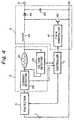
- FIG. 4 is a block diagram schematically showing abattery pack embodying the present invention.
- To better understand the present invention, a briefreference will be made to a conventional battery pack for aportable apparatus, particularly a handy phone. As shown, thebattery pack has an Ni-Cd
secondary battery 71 by way of example. A PCT (Positive Temperature Coefficient)device 72is a protective device against overcurrent. Athermistor 73is responsive to temperature elevation to occur when thebattery 71 is charged. A diode 74 has a charge terminal and adischarge terminal separate from each other in order toobviate discharge toward the charge terminal. The Ni-Cdbattery 71 has a discharge characteristic, i.e., batterycapacity and terminal voltage little susceptible to theambient atmospheric temperature. However, a lithium ionsecondary battery is advantageous over the Ni-Cd battery 71in respect of the small size, light weight configuration of aportable apparatus, as stated earlier. - FIG. 2 shows another conventional battery pack using alithium ion secondary battery. As shown, the battery pack hasa lithium ion secondary battery 81 and a
protection 82consisting of an overdischarge protecting circuit, anovercharge protecting circuit, and an overcurrent protectingcircuit. However, the lithium ion battery 81 is susceptible tothe ambient atmospheric temperature, i.e., its terminalvoltage noticeably drops at low temperatures, as also statedearlier. FIG. 3 shows the discharge temperaturecharacteristic of a lithium ion secondary battery specifically.As shown, the voltage of the battery is far lower at -20°Cthan at 21°C, 40°C and 60°C. Therefore, the output voltage ofthe above battery pack 81 drops at low temperatures. As a result, a portable apparatus loaded with the battery pack 81cannot be powered by a constant voltage. - Referring to FIG. 4, a battery pack embodying thepresent invention will be described. As shown, the batterypack has a lithium ion
secondary battery 1. A temperaturesensing circuit 2 is responsive to temperature around thebattery pack. A controller 3 controls the boosting ratio inresponse to a signal output from the temperature sensingcircuit 2. A boosting circuit 4 boosts a voltage in response toa control signal fed from the controller 3, as will bedescribed specifically later. There are also shown in FIG. 4 aprotection 5 consisting of an overdischarge protecting circuit,an overcharge protecting circuit, and an overcurrentprotecting circuit, and an output terminal 6. - The temperature sensing circuit 2 has a
thermistor 21,acurrent detector 22 for detecting a current flowing throughthethermistor 21, and avoltage detector 23 for detecting avoltage acting on thethermistor 21. The dischargetemperature characteristic of thesecondary battery 1 isstored in the controller 3 beforehand. The controller 3computes a temperature based on the outputs of thecurrentdetector 22 andvoltage detector 23, computes a voltagebased on the computed temperature, and then computes aboosting ratio setting up a preselected voltage. The boostingcircuit 4 is a PWM (Pulse Width Modulation) control type switching regulator consisting of aPWM controller 41, asemiconductor switching device 42, aninductor 43, adiode 44, and acapacitor 45. - In operation, the resistance of the
thermistor 21 varieswith the varying ambient atmospheric temperature. As aresult, the current and voltage of thethermistor 21 vary. Thecurrent detector 22 andvoltage detector 23 send theiroutputs respectively representative of the above current andvoltage to the controller 3. In response, the controller 3computes a temperature around the battery pack and thendetermines a boosting ratio by referencing the dischargetemperature characteristic of thelithium ion battery 1stored therein. - Specifically, assume that the
lithium ion battery 1 hasthe discharge temperature characteristic shown in FIG. 3, andthat the temperature is about -20°C. Then, the controller 3feeds a control signal to the boosting circuit 4 to cause it toraise the voltage by about 0.4 V which is the differencebetween the voltage at, e.g., 21°C and the voltage at -20°C. Inresponse, theboosting circuit 41 causes itsPWM controller 41 to control the ON/OFF time ratio of theswitching device 42, thereby raising the voltage. At the same time, thecontroller 3 delivers a control signal to theprotection 5. Inresponse, theprotection 5 lowers its overdischargeprotection voltage by the value raised by the boosting circuit 4. As a result, a preselected voltage expected to appear a tnormal temperatures successfully appears on the outputterminal despite the low temperature around the battery pack. - In summary, it will be seen that the present inventionprovides a battery pack using a lithium ion secondary batteryand capable of correcting, when temperature around thebattery pack is low and causes the voltage of the battery todrop due to the characteristic of the battery, the voltage to avoltage expected to appear at normal temperatures.Therefore, the battery pack outputs a constant voltage on itsoutput terminal without regard to the ambient atmospherictemperature.
- Various modifications will become possible for thoseskilled in the art after receiving the teachings of the presentdisclosure without departing from the scope thereof.
Claims (3)
- A battery pack including a lithium ion secondary battery(1), comprising:
a protection circuit (5) consisting of an overdischargeprotecting circuit, an overcharge protecting circuit, and anovercurrent protecting circuit;
characterized bya temperature sensing circuit (2) consisting of a temperaturenon-linear element, a current detector, and a voltagedetector;a controller (3) for controlling a boosting ratio inresponse to an output of said temperature sensing circuit(2); anda boosting circuit (4) for boosting an output voltageof said lithium ion secondary battery (1) in response to acontrol signal output from said controller (3). - A battery pack as claimed in claim 1, wherein said temperaturenon-linear element comprises a thermistor (21).
- A battery pack as claimed in claim 1, wherein said controlcircuit (3) feeds a control signal to said overdischargeprotection circuit in order to control an overdischarge protectionvoltage of said overdischarge protection circuit.
Applications Claiming Priority (3)
| Application Number | Priority Date | Filing Date | Title |
|---|---|---|---|
| JP21712995 | 1995-08-25 | ||
| JP7217129AJP2861879B2 (en) | 1995-08-25 | 1995-08-25 | Battery pack |
| JP217129/95 | 1995-08-25 |
Publications (3)
| Publication Number | Publication Date |
|---|---|
| EP0760547A2 EP0760547A2 (en) | 1997-03-05 |
| EP0760547A3 EP0760547A3 (en) | 1997-05-28 |
| EP0760547B1true EP0760547B1 (en) | 2001-12-19 |
Family
ID=16699314
Family Applications (1)
| Application Number | Title | Priority Date | Filing Date |
|---|---|---|---|
| EP96113497AExpired - LifetimeEP0760547B1 (en) | 1995-08-25 | 1996-08-22 | Battery pack with a lithium ion secondary battery |
Country Status (3)
| Country | Link |
|---|---|
| US (1) | US5708351A (en) |
| EP (1) | EP0760547B1 (en) |
| JP (1) | JP2861879B2 (en) |
Families Citing this family (31)
| Publication number | Priority date | Publication date | Assignee | Title |
|---|---|---|---|---|
| US5742148A (en)* | 1992-11-24 | 1998-04-21 | Seiko Instruments Inc. | Charge/discharge control circuit and chargeable electric power source apparatus |
| US5731693A (en)* | 1996-10-23 | 1998-03-24 | Eldec Corporation (A Washington Corporation) | Power supply for cellular communication stations |
| GB2321140A (en)* | 1997-01-13 | 1998-07-15 | Samsung Electronics Co Ltd | Battery charger control responsive to ambient temperature |
| JP3767767B2 (en)* | 1997-11-28 | 2006-04-19 | ソニー株式会社 | Charge control method and charge control device |
| US5990664A (en)* | 1998-03-30 | 1999-11-23 | Eveready Battery Company, Inc. | Process and apparatus for modulating terminal voltage of battery |
| US6169384B1 (en)* | 1999-04-19 | 2001-01-02 | Packard Bell Nec Inc. | Power source system for portable electronic devices |
| TW460083U (en)* | 1999-07-19 | 2001-10-11 | Mobiletech Inc | Power conversion device |
| JP3670522B2 (en)* | 1999-07-30 | 2005-07-13 | 富士通株式会社 | Battery pack |
| US6160389A (en)* | 1999-08-27 | 2000-12-12 | Black & Decker Inc. | Battery charger with low heat dissipation |
| JP4030312B2 (en) | 2000-03-07 | 2008-01-09 | 帝人株式会社 | Lithium ion secondary battery, battery pack and charging method |
| US7094497B2 (en)* | 2000-03-07 | 2006-08-22 | Teijin Limited | Separator for lithium ion secondary battery |
| US6881438B2 (en)* | 2000-03-07 | 2005-04-19 | Teijin Limited | Process for production of composite porous film |
| US6366153B1 (en)* | 2000-05-09 | 2002-04-02 | Delphi Technologies, Inc. | Thermal management of an electronic switch |
| US7589500B2 (en) | 2002-11-22 | 2009-09-15 | Milwaukee Electric Tool Corporation | Method and system for battery protection |
| US7157882B2 (en)* | 2002-11-22 | 2007-01-02 | Milwaukee Electric Tool Corporation | Method and system for battery protection employing a selectively-actuated switch |
| US8471532B2 (en) | 2002-11-22 | 2013-06-25 | Milwaukee Electric Tool Corporation | Battery pack |
| US7776475B2 (en) | 2004-08-03 | 2010-08-17 | Samsung Sdi Co., Ltd. | Lithium rechargeable battery and lithium rechargeable battery pack |
| US20060119322A1 (en)* | 2004-12-04 | 2006-06-08 | Hossein Maleki | Battery pack with temperature activated boost |
| KR100762086B1 (en)* | 2005-01-14 | 2007-10-01 | 주식회사 엘지화학 | Apparatus and method for bucking battery |
| WO2007043392A1 (en) | 2005-10-03 | 2007-04-19 | Densei-Lambda Kabushiki Kaisha | Battery pack |
| US7859226B2 (en) | 2007-07-17 | 2010-12-28 | Tdk-Lambda Corporation | Method and device for safety protection of secondary battery |
| KR101192532B1 (en)* | 2009-02-23 | 2012-10-17 | 도요타지도샤가부시키가이샤 | Battery system and automobile |
| DE102009023787A1 (en)* | 2009-06-03 | 2011-01-27 | Osram Gesellschaft mit beschränkter Haftung | Circuit arrangement and method for operating a low-pressure discharge lamp |
| US8974933B2 (en)* | 2010-08-27 | 2015-03-10 | Motorola Solutions, Inc. | Method and apparatus for preventing electrolysis on battery contacts in a dual-contact battery system |
| CN102157910B (en)* | 2010-12-24 | 2014-05-07 | 深圳和而泰智能控制股份有限公司 | Detection device and method as well as loads using detection device or method |
| DE102011083307A1 (en)* | 2011-09-23 | 2013-03-28 | Continental Automotive Gmbh | Device for measuring a battery current |
| US9831691B2 (en)* | 2012-09-18 | 2017-11-28 | Nec Energy Devices, Ltd. | Power storage system and cell protection method which protects the cell by both cutting from the cell pack and the cell pack from the system |
| CN102931842A (en)* | 2012-10-12 | 2013-02-13 | 华为技术有限公司 | Chip dynamic voltage regulating circuit and terminal equipment |
| CN104348192B (en)* | 2013-07-23 | 2018-04-27 | 惠州市吉瑞科技有限公司 | A kind of electronic cigarette USB charger |
| CN103928911B (en)* | 2014-04-25 | 2016-12-21 | 西安科技大学 | Short-circuit inductance energy bypass circuit of intrinsic safety Boost converter |
| CN114039396B (en)* | 2021-11-30 | 2022-12-13 | 国网甘肃省电力公司金昌供电公司 | A charging protection device for electronic communication equipment capable of protecting batteries |
Citations (2)
| Publication number | Priority date | Publication date | Assignee | Title |
|---|---|---|---|---|
| JPH0433271A (en)* | 1990-05-28 | 1992-02-04 | Asahi Chem Ind Co Ltd | Charging type battery device |
| JPH0475430A (en)* | 1990-07-18 | 1992-03-10 | Asahi Chem Ind Co Ltd | Rechargeable power unit |
Family Cites Families (13)
| Publication number | Priority date | Publication date | Assignee | Title |
|---|---|---|---|---|
| JPS5485767A (en)* | 1977-12-20 | 1979-07-07 | Seiko Instr & Electronics Ltd | Electronic watch |
| JPS58225368A (en)* | 1982-06-25 | 1983-12-27 | Matsushita Electric Ind Co Ltd | Battery remaining capacity determination circuit |
| JPS60104925A (en)* | 1983-11-14 | 1985-06-10 | Nippon Denso Co Ltd | Driving device of liquid crystal element |
| JPS62223680A (en)* | 1986-03-25 | 1987-10-01 | Matsushita Electric Works Ltd | Dead battery detecting device |
| JPH02133038A (en)* | 1988-11-11 | 1990-05-22 | Matsushita Electric Ind Co Ltd | power system |
| JPH03180784A (en)* | 1989-12-11 | 1991-08-06 | Canon Inc | Calculator for residual capacity of battery |
| JPH03294660A (en)* | 1990-04-11 | 1991-12-25 | Mitsubishi Electric Corp | Auxiliary device for engine start |
| JPH04127620A (en)* | 1990-09-18 | 1992-04-28 | Toshiba Corp | Mobile radio communication equipment |
| US5572108A (en)* | 1992-01-07 | 1996-11-05 | Windes; John A. | Power system using battery-charged capacitors |
| JPH06124731A (en)* | 1992-08-31 | 1994-05-06 | Toshiba Corp | External battery connection attachment, battery pack and battery identification control method |
| JP3291530B2 (en)* | 1992-09-17 | 2002-06-10 | ソニー株式会社 | Battery protection circuit |
| JP3272108B2 (en)* | 1993-07-07 | 2002-04-08 | 三洋電機株式会社 | Battery pack |
| AU691507B2 (en)* | 1993-09-17 | 1998-05-21 | Nec Corporation | Charging and discharging circuit for preventing overcharge and overdischarge of rechargable battery pack consisting of a plurality of rechargable batteries |
- 1995
- 1995-08-25JPJP7217129Apatent/JP2861879B2/ennot_activeExpired - Fee Related
- 1996
- 1996-08-20USUS08/699,953patent/US5708351A/ennot_activeExpired - Fee Related
- 1996-08-22EPEP96113497Apatent/EP0760547B1/ennot_activeExpired - Lifetime
Patent Citations (2)
| Publication number | Priority date | Publication date | Assignee | Title |
|---|---|---|---|---|
| JPH0433271A (en)* | 1990-05-28 | 1992-02-04 | Asahi Chem Ind Co Ltd | Charging type battery device |
| JPH0475430A (en)* | 1990-07-18 | 1992-03-10 | Asahi Chem Ind Co Ltd | Rechargeable power unit |
Also Published As
| Publication number | Publication date |
|---|---|
| JPH0963652A (en) | 1997-03-07 |
| JP2861879B2 (en) | 1999-02-24 |
| EP0760547A2 (en) | 1997-03-05 |
| US5708351A (en) | 1998-01-13 |
| EP0760547A3 (en) | 1997-05-28 |
Similar Documents
| Publication | Publication Date | Title |
|---|---|---|
| EP0760547B1 (en) | Battery pack with a lithium ion secondary battery | |
| US5296797A (en) | Pulse modulated battery charging system | |
| US7990109B2 (en) | Temperature and polarization voltage compensation system | |
| US5804944A (en) | Battery protection system and process for charging a battery | |
| US5640079A (en) | Battery charger for portable rechargeable batteries | |
| US5861730A (en) | Battery charging apparatus | |
| US8436583B2 (en) | Multiple cell battery charger configured with a parallel topology | |
| US4670703A (en) | Battery charger with three different charging rates | |
| US5602460A (en) | Overcharge current protection circuit and battery pack using same | |
| EP1796243B1 (en) | Methods of charging battery packs for cordless power tool systems | |
| US4310793A (en) | Charge/float motor vehicle electrical system | |
| JPH11242966A (en) | Method and apparatus for protecting battery pack | |
| EP0580351B1 (en) | Battery charging apparatus | |
| JP3267998B2 (en) | Battery pack charger | |
| JP3326324B2 (en) | Secondary battery protection circuit | |
| AU683475B2 (en) | Electronic device having internal charge regulator | |
| JP3419122B2 (en) | Battery protection device | |
| WO1995001699A1 (en) | Electronic device for controlling application of a charging current thereto and associated method therefor | |
| JP2002374630A (en) | Battery pack | |
| JP4189987B2 (en) | Battery pack and external host device system using the battery pack as a power source | |
| JP3492903B2 (en) | Lithium ion secondary battery charging system and charger | |
| JP3457681B2 (en) | Charging device | |
| JP2654106B2 (en) | Battery pack | |
| JP3450676B2 (en) | Secondary battery device | |
| WO1995008238A1 (en) | Charge regulator for electronic device and associated method |
Legal Events
| Date | Code | Title | Description |
|---|---|---|---|
| PUAI | Public reference made under article 153(3) epc to a published international application that has entered the european phase | Free format text:ORIGINAL CODE: 0009012 | |
| AK | Designated contracting states | Kind code of ref document:A2 Designated state(s):FR GB IT | |
| PUAL | Search report despatched | Free format text:ORIGINAL CODE: 0009013 | |
| AK | Designated contracting states | Kind code of ref document:A3 Designated state(s):FR GB IT | |
| 17P | Request for examination filed | Effective date:19970415 | |
| 17Q | First examination report despatched | Effective date:19991202 | |
| GRAG | Despatch of communication of intention to grant | Free format text:ORIGINAL CODE: EPIDOS AGRA | |
| GRAG | Despatch of communication of intention to grant | Free format text:ORIGINAL CODE: EPIDOS AGRA | |
| GRAH | Despatch of communication of intention to grant a patent | Free format text:ORIGINAL CODE: EPIDOS IGRA | |
| GRAH | Despatch of communication of intention to grant a patent | Free format text:ORIGINAL CODE: EPIDOS IGRA | |
| GRAA | (expected) grant | Free format text:ORIGINAL CODE: 0009210 | |
| AK | Designated contracting states | Kind code of ref document:B1 Designated state(s):FR GB IT | |
| REG | Reference to a national code | Ref country code:GB Ref legal event code:IF02 | |
| ET | Fr: translation filed | ||
| PLBE | No opposition filed within time limit | Free format text:ORIGINAL CODE: 0009261 | |
| STAA | Information on the status of an ep patent application or granted ep patent | Free format text:STATUS: NO OPPOSITION FILED WITHIN TIME LIMIT | |
| 26N | No opposition filed | ||
| PGFP | Annual fee paid to national office [announced via postgrant information from national office to epo] | Ref country code:FR Payment date:20050809 Year of fee payment:10 | |
| PGFP | Annual fee paid to national office [announced via postgrant information from national office to epo] | Ref country code:GB Payment date:20050817 Year of fee payment:10 | |
| PGFP | Annual fee paid to national office [announced via postgrant information from national office to epo] | Ref country code:IT Payment date:20060831 Year of fee payment:11 | |
| GBPC | Gb: european patent ceased through non-payment of renewal fee | Effective date:20060822 | |
| REG | Reference to a national code | Ref country code:FR Ref legal event code:ST Effective date:20070430 | |
| PG25 | Lapsed in a contracting state [announced via postgrant information from national office to epo] | Ref country code:GB Free format text:LAPSE BECAUSE OF NON-PAYMENT OF DUE FEES Effective date:20060822 | |
| PG25 | Lapsed in a contracting state [announced via postgrant information from national office to epo] | Ref country code:FR Free format text:LAPSE BECAUSE OF NON-PAYMENT OF DUE FEES Effective date:20060831 | |
| PG25 | Lapsed in a contracting state [announced via postgrant information from national office to epo] | Ref country code:IT Free format text:LAPSE BECAUSE OF NON-PAYMENT OF DUE FEES Effective date:20070822 |