EP0759631A1 - Process and apparatus for the fabrication of holes in a layer of photosensitive material, especially for the fabrication of electron sources - Google Patents
Process and apparatus for the fabrication of holes in a layer of photosensitive material, especially for the fabrication of electron sourcesDownload PDFInfo
- Publication number
- EP0759631A1 EP0759631A1EP96401787AEP96401787AEP0759631A1EP 0759631 A1EP0759631 A1EP 0759631A1EP 96401787 AEP96401787 AEP 96401787AEP 96401787 AEP96401787 AEP 96401787AEP 0759631 A1EP0759631 A1EP 0759631A1
- Authority
- EP
- European Patent Office
- Prior art keywords
- layer
- membrane
- photosensitive material
- photosensitive
- holes
- Prior art date
- Legal status (The legal status is an assumption and is not a legal conclusion. Google has not performed a legal analysis and makes no representation as to the accuracy of the status listed.)
- Granted
Links
- 238000000034methodMethods0.000titleclaimsabstractdescription40
- 239000000463materialSubstances0.000titleclaimsdescription34
- 238000004519manufacturing processMethods0.000titleclaimsdescription24
- 239000012528membraneSubstances0.000claimsdescription62
- 239000000758substrateSubstances0.000claimsdescription28
- 239000011347resinSubstances0.000claimsdescription18
- 229920005989resinPolymers0.000claimsdescription18
- 239000004020conductorSubstances0.000claimsdescription13
- 238000005530etchingMethods0.000claimsdescription4
- 238000001914filtrationMethods0.000claimsdescription4
- 238000003825pressingMethods0.000claimsdescription4
- 238000000137annealingMethods0.000claims1
- 238000007599dischargingMethods0.000claims1
- 230000003287optical effectEffects0.000abstractdescription5
- 230000000873masking effectEffects0.000abstract1
- PXHVJJICTQNCMI-UHFFFAOYSA-NNickelChemical compound[Ni]PXHVJJICTQNCMI-UHFFFAOYSA-N0.000description6
- 239000012212insulatorSubstances0.000description4
- 238000000151depositionMethods0.000description3
- 150000002500ionsChemical class0.000description3
- 229910052759nickelInorganic materials0.000description3
- 238000000206photolithographyMethods0.000description3
- ZOKXTWBITQBERF-UHFFFAOYSA-NMolybdenumChemical compound[Mo]ZOKXTWBITQBERF-UHFFFAOYSA-N0.000description2
- VYPSYNLAJGMNEJ-UHFFFAOYSA-NSilicium dioxideChemical compoundO=[Si]=OVYPSYNLAJGMNEJ-UHFFFAOYSA-N0.000description2
- 230000003667anti-reflective effectEffects0.000description2
- 230000015572biosynthetic processEffects0.000description2
- 229910052751metalInorganic materials0.000description2
- 239000002184metalSubstances0.000description2
- 238000004377microelectronicMethods0.000description2
- 229910052750molybdenumInorganic materials0.000description2
- 239000011733molybdenumSubstances0.000description2
- 229920006254polymer filmPolymers0.000description2
- 101100269850Caenorhabditis elegans mask-1 geneProteins0.000description1
- 206010019345Heat strokeDiseases0.000description1
- VAYOSLLFUXYJDT-RDTXWAMCSA-NLysergic acid diethylamideChemical compoundC1=CC(C=2[C@H](N(C)C[C@@H](C=2)C(=O)N(CC)CC)C2)=C3C2=CNC3=C1VAYOSLLFUXYJDT-RDTXWAMCSA-N0.000description1
- XUIMIQQOPSSXEZ-UHFFFAOYSA-NSiliconChemical compound[Si]XUIMIQQOPSSXEZ-UHFFFAOYSA-N0.000description1
- 208000007180SunstrokeDiseases0.000description1
- 238000005136cathodoluminescenceMethods0.000description1
- 238000007796conventional methodMethods0.000description1
- 230000008021depositionEffects0.000description1
- 238000006073displacement reactionMethods0.000description1
- 238000004090dissolutionMethods0.000description1
- 238000009826distributionMethods0.000description1
- 239000011521glassSubstances0.000description1
- AMGQUBHHOARCQH-UHFFFAOYSA-Nindium;oxotinChemical compound[In].[Sn]=OAMGQUBHHOARCQH-UHFFFAOYSA-N0.000description1
- 230000010354integrationEffects0.000description1
- 230000003993interactionEffects0.000description1
- 230000001678irradiating effectEffects0.000description1
- 239000004973liquid crystal related substanceSubstances0.000description1
- 229910052758niobiumInorganic materials0.000description1
- 239000010955niobiumSubstances0.000description1
- GUCVJGMIXFAOAE-UHFFFAOYSA-Nniobium atomChemical compound[Nb]GUCVJGMIXFAOAE-UHFFFAOYSA-N0.000description1
- 230000003071parasitic effectEffects0.000description1
- 229910052710siliconInorganic materials0.000description1
- 239000010703siliconSubstances0.000description1
- 239000000377silicon dioxideSubstances0.000description1
- 239000012780transparent materialSubstances0.000description1
- 235000012431wafersNutrition0.000description1
Images

Classifications
- G—PHYSICS
- G03—PHOTOGRAPHY; CINEMATOGRAPHY; ANALOGOUS TECHNIQUES USING WAVES OTHER THAN OPTICAL WAVES; ELECTROGRAPHY; HOLOGRAPHY
- G03F—PHOTOMECHANICAL PRODUCTION OF TEXTURED OR PATTERNED SURFACES, e.g. FOR PRINTING, FOR PROCESSING OF SEMICONDUCTOR DEVICES; MATERIALS THEREFOR; ORIGINALS THEREFOR; APPARATUS SPECIALLY ADAPTED THEREFOR
- G03F1/00—Originals for photomechanical production of textured or patterned surfaces, e.g., masks, photo-masks, reticles; Mask blanks or pellicles therefor; Containers specially adapted therefor; Preparation thereof
- G03F1/20—Masks or mask blanks for imaging by charged particle beam [CPB] radiation, e.g. by electron beam; Preparation thereof
- H—ELECTRICITY
- H01—ELECTRIC ELEMENTS
- H01J—ELECTRIC DISCHARGE TUBES OR DISCHARGE LAMPS
- H01J9/00—Apparatus or processes specially adapted for the manufacture, installation, removal, maintenance of electric discharge tubes, discharge lamps, or parts thereof; Recovery of material from discharge tubes or lamps
- H01J9/02—Manufacture of electrodes or electrode systems
- H01J9/022—Manufacture of electrodes or electrode systems of cold cathodes
- H01J9/025—Manufacture of electrodes or electrode systems of cold cathodes of field emission cathodes
Definitions
- the present inventionrelates to a method and a device for forming holes in a layer of photosensitive material.
- the inventionmakes it possible, for example, to manufacture large micropoint flat screens, for example greater than 14 inches (approximately 35 cm), and even micropoint flat screens whose area is close to 1 m 2 .
- Sources of electrons with microtip emissive cathodes and their manufacturing methodsare described for example in documents (1), (2), (3) and (4) referenced at the end of this description to which reference may be made. .
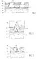
- FIG. 1shows an already developed structure, comprising, a substrate 2 surmounted by an insulator 4, a system of cathode conductors 6, a resistive layer 7 and grids 8, superimposed in crossed form, with an intermediate insulator 10, and a layer 12, for example made of nickel, deposited on the surface to serve as a mask during operations for producing microtips.
- This layer 12 of nickel, the grids 8 and the insulator 10are pierced with holes 14, at the bottom of which it is a question of subsequently depositing the microtips made of a conductive metal in electrical connection with the cathode conductors 6 through the layer resistive 7.
- This layer 16has a thickness of approximately 1.8 ⁇ m.
- This deposition techniquemakes it possible to obtain cones 18 of molybdenum housed in the holes 14 and having a height of 1.2 to 1.5 ⁇ m.
- the nickel layer 12is then selectively dissolved by an electrochemical process, so as to see, as shown in FIG. 3, the perforated grids 8, for example made of niobium, and at reveal the electron-emitting microtips 18.
- the known method thus described with reference to FIGS. 1, 2 and 3is one of those which have been applied to date for producing the microtips of electron sources with emissive cathodes with microtips. .
- Direct projectionrequires the production of a large scale mask 1 with submicron patterns. These patterns are generally composed of metal in a thin layer deposited on a silica or glass substrate.
- a mask 20 to 50 mm sideis used, for example, which requires repeating a large number of times the exposure operation which is necessary for photolithography, to cover the total surface of the electron source.
- An object of the present inventionis precisely to provide a device and a method allowing the formation of holes uniformly over large areas, and not having the limitations of the methods mentioned above.
- An object of the inventionis also to apply the method to the manufacture of electron sources.
- the inventionmore specifically relates to a method of forming holes in a layer of photosensitive material, with a free surface, disposed on a substrate, characterized in that the whole surface is plated free from the layer of photosensitive material a microperforated membrane, of the filtration membrane type with microperforations; the photosensitive material layer is exposed through the membrane with an exposure light so as to impress areas of the photosensitive layer corresponding to the microperforations of the membrane; the membrane is separated from the layer of photosensitive material thus exposed, and the photosensitive layer is developed to form in this layer holes corresponding to the exposed areas.
- Microperforated membranesare commercially available; these are in particular membranes of the type used for filtration.
- the method of the inventionis less expensive than the known methods of photolithography with masks produced in accordance with microelectronic techniques.
- Microperforated membranesare also available in rolls of several meters or tens of meters, which makes it possible to treat large areas.
- the microperforationsare according to one aspect of the invention, distributed randomly over the entire surface of the membrane with a substantially constant density.
- the densitycan range from a few thousand to a few tens of thousands of holes per square millimeter.
- the diameter of the microperforationscan be chosen according to the size of the holes to be made. By way of example, this diameter can be between 0.2 and 20 ⁇ m for the applications envisaged.
- the membraneis a non-transparent material, so as to form a mask, and preferably opaque to the exposure light used.
- the layer of photosensitive materialcan be a resin. It is possible in this case to anneal this layer to increase its hardness and avoid possible deformations thereof during the subsequent stages of the process of the invention.
- This processis characterized in that these holes are obtained by forming a positive photosensitive resin layer at least in said areas, on the surface of the structure, by forming openings (holes) in the resin layer according to the process described above. above and by etching the grids and the insulating layer through these openings formed in the resin layer.
- the application of the method of the invention to the production of electron sources, in particular for display screensis very advantageous insofar as it makes it possible to form large resin masks, and therefore to produce large screens. Furthermore, the method is suitable for mass production of resin masks.
- the inventionalso relates to an insolation device for the formation of holes in a layer of photosensitive material disposed on a substrate, the device comprising a substrate holder for receiving the substrate with a layer of photosensitive material, a coil supply of virgin membrane with microperforations, and a membrane receiving coil after use, the coils being arranged so as to deliver a portion of virgin membrane stretched between them, with a surface corresponding to the surface of the layer of photosensitive material, a conveyor for moving the substrate holder from a substrate loading station to a station opposite the blank membrane portion, then to a substrate unloading station, means for pressing the layer of photosensitive material against the portion of virgin membrane then to separate the photosensitive layer from this portion of membrane after a step of insulating the p layer hot-sensitive, and an insolation light source arranged facing the portion of the virgin membrane for exposing the layer of photosensitive material through the microperforations of the membrane.
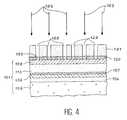
- the reference 101designates in FIG. 4 a stack of the type used for the manufacture of electron sources.
- parts of the stack 101which correspond to parts of the stack shown in FIGS. 1 to 3 are designated by the same references to which 100 has been added.
- the stack 101comprises a substrate 102, surmounted in order by an electrically insulating layer 104, a system of cathode electrical conductors 106, a resistive layer 107, an intermediate layer 110, electrically insulating , and grids 108 superimposed, in cross form.
- An etching maskis formed on the surface of the stack 101, that is to say above the grids 108 with openings which correspond to holes which it is desired to make in the layers 108 and 110 of the 'stacking 101.
- the holes that one wishes to make in the layers 108 and 110correspond to the holes 14 shown in FIG. 1.
- a layer of photosensitive resin 120is formed on the surface of the stack 101, that is to say on the layer 108, and openings (holes) are made therein according to the method of the invention. .
- a membrane 121is coated on the layer 120 with microperforations 122, the photosensitive resin layer is exposed with an insolation light 123 to impress areas 125 of the layer 120 corresponding to microperforations 122 of the membrane 121, spreads the membrane 121 and develops the resin layer.
- the membrane 121can be effectively pressed onto the layer 120 by means of electrostatic forces, for example.
- the membrane 121which plays the role of an optical mask, is pressed against the resin layer 120. This makes it possible to uniformly cover this layer and thus avoid any stray light between it - and the membrane.
- the membrane 121can be a microperforated filtration membrane of the type of membranes sold by the Company Whatman in Belgium. However, any other type of membrane may be suitable. Its thickness, from a few micrometers to a few tens of micrometers, is chosen to suit the passage of light through the microperforations 122.
- the membrane 121can also be manufactured by irradiating, for example, a polymer film with heavy ions with an energy of the order of 1 MeV then by dissolving the parts of the polymer film which have undergone an interaction with the electronic procession of ions.
- a polymer film with heavy ions with an energy of the order of 1 MeVthen by dissolving the parts of the polymer film which have undergone an interaction with the electronic procession of ions.
- the material of the membrane 121is chosen to be opaque to the exposure light 123, so as to allow the exposure light to pass only through the microperforations. 122.
- a photosensitive resincan be chosen whose dissolution rate during development is much greater in the areas exposed through the microperforations only in masked areas.
- the insolation lightcomes from a parallel ultraviolet light source (not shown) preferably arranged so that the rays reach the upper surface of the membrane perpendicularly.
- the exposure timeis chosen to be long enough for the resin layer 120 to be exposed over its entire thickness in the areas 125.
- the membrane 121is removed from the surface of the layer 120, and this layer is developed to form holes (openings) in the exposed areas.
- Figures 5, 6 and 7illustrate a particular embodiment of the method of the invention and show an apparatus provided for this purpose. Identical or similar parts of Figures 4, 5, 6 and 7 have the same references. It is thus possible to refer to the description of FIG. 4 for certain corresponding parts of FIGS. 5, 6 and 7.
- the apparatus provided for the implementation of the invention in the context of on-line manufacturingcomprises, as shown in FIG. 5, a chain with a conveyor 133 capable of moving a sample to be treated, successively from a station loading 126 to an insolation station 127 where the sample is located opposite a microperforated membrane 121, then from this station 127 to an unloading station 128.
- the sample to be treatedcomposed of a stack 101 covered with a layer of photosensitive material 120, is placed on a substrate holder 130 at the loading station 126.
- the apparatusalso comprises a virgin membrane distribution system for the exposure of the photosensitive layer 120.
- This systemcomprises a first reel 131 of supply with a roll of virgin membrane and a reel 132 for receiving the membrane after use.
- This systemmakes it possible to use a portion of virgin membrane, that is to say one which has not undergone sunstroke, for each new sample to be treated.
- the coils 131 and 132are arranged so as to tension between them a portion of virgin membrane 121 with a surface corresponding to the surface of the photosensitive layer.
- the tension of the membrane 121can be adjusted to flatten it uniformly on the photosensitive layer 120.
- Means of relative displacement of the substrate holder 130are provided at the insolation station perpendicular to the membrane 121. These means are shown in FIG. 6 in a simplified manner by an arrow 136. It is possible, for example, to use a pneumatic cylinder for lifting the substrate holder and thus pressing the membrane 121 on the photosensitive layer 120.
- the layer 120is exposed in this position by an exposure light 123 in accordance with the description given with respect to FIG. 4.
- the light 123comes for example from a source of ultraviolet exposure not shown.
- the whole apparatus for carrying out the processis preferably placed in an inactinic light environment which does not irradiate the resin in a parasitic manner.
- the layer 120is separated from the membrane 121 by lowering the substrate holder 130, and the conveyor 133 moves the assembly formed by the substrate holder 130 and the substrate 101 covered by layer 120, towards the unloading station.
- the substrate and layer 120are discharged from the substrate holder and the photosensitive material of layer 120 is developed to form, as described above, holes, or openings, in the exposed areas.
- the method of forming holes in a layer of photosensitive materialcan be used in the production of large-area microtip screens.
- Another application of the methodcan be the production of microperforated membranes on substrates of rigid materials, such as silicon wafers. These are then etched through a mask with holes made in accordance with the invention.
- engraved optical systemsof the anti-reflective type, can be produced over large areas.
- a transparent oxide layerfor example, indium tin oxide (ITO)
- ITOindium tin oxide
- pierced with a multitude of holes with a diameter of the order of 1 ⁇ mcan serve as an anti-reflective layer.
- the ITO layeris then etched with a mask of photosensitive material in which holes (or openings) are made in accordance with the invention.
Landscapes
- Engineering & Computer Science (AREA)
- Manufacturing & Machinery (AREA)
- Physics & Mathematics (AREA)
- General Physics & Mathematics (AREA)
- Cold Cathode And The Manufacture (AREA)
- Electron Beam Exposure (AREA)
Abstract
Description
Translated fromFrenchLa présente invention concerne un procédé et un dispositif de formation de trous dans une couche de matériau photosensible.The present invention relates to a method and a device for forming holes in a layer of photosensitive material.
Elle s'applique notamment à la fabrication de sources d'électrons à cathodes émissives à micropointes qui sont utilisées en particulier pour la réalisation de dispositifs de visualisation par cathodoluminescence excitée par émission de champ.It applies in particular to the manufacture of electron sources with emissive cathodes with microtips which are used in particular for the production of display devices by cathodoluminescence excited by field emission.
L'invention permet par exemple de fabriquer des écrans plats à micropointes de grande taille, par exemple supérieure à 14 pouces (environ 35 cm), et même des écrans plats à micropointes dont la superficie est voisine de 1 m2.The invention makes it possible, for example, to manufacture large micropoint flat screens, for example greater than 14 inches (approximately 35 cm), and even micropoint flat screens whose area is close to 1 m2 .
Bien entendu des écrans de taille nettement plus grande peuvent être élaborés grâce à la présente invention.Of course, screens of significantly larger size can be produced thanks to the present invention.
Des sources d'électrons à cathodes émissives à micropointes et leurs procédés de fabrication sont décrits par exemple dans les documents (1), (2), (3) et (4) référencés à la fin de la présente description auxquels on peut se reporter.Sources of electrons with microtip emissive cathodes and their manufacturing methods are described for example in documents (1), (2), (3) and (4) referenced at the end of this description to which reference may be made. .
Pour faciliter la compréhension du problème technique résolu par la présente invention, on -décrit ci-après un exemple connu de procédé de fabrication d'une source d'électrons à cathodes émissives à micropointes.To facilitate understanding of the technical problem solved by the present invention, there is described below a known example of a method for manufacturing an electron source with microtip emissive cathodes.
On se référera aux figures 1 à 3 des dessins annexés.Reference is made to Figures 1 to 3 of the accompanying drawings.
La figure 1 montre une structure déjà élaborée, comprenant, un substrat 2 surmonté d'un isolant 4, un système de conducteurs cathodiques 6, une couche résistive 7 et des grilles 8, superposés sous forme croisée, avec un isolant intermédiaire 10, et une couche 12, par exemple en nickel, déposée en surface pour servir de masque lors d'opérations de réalisation de micropointes.FIG. 1 shows an already developed structure, comprising, a
Cette couche 12 de nickel, les grilles 8 et l'isolant 10 sont percés de trous 14, au fond desquels il s'agit de déposer ultérieurement les micropointes constituées d'un métal conducteur en liaison électrique avec les conducteurs cathodiques 6 à travers la couche résistive 7.This
La réalisation des micropointes va maintenant être expliquée en faisant référence à la figure 2.The production of the microtips will now be explained with reference to FIG. 2.
On commence d'abord par effectuer par exemple le dépôt d'une couche en molybdène 16 sur l'ensemble de la structure.We start first by performing for example the deposition of a
Cette couche 16 présente une épaisseur d'environ 1,8 µm.This
Elle est déposée sous incidence normale par rapport à la surface de la structure.It is deposited under normal incidence relative to the surface of the structure.
Cette technique de dépôt permet d'obtenir des cônes 18 en molybdène logés dans les trous 14 et ayant une hauteur de 1,2 à 1,5 µm.This deposition technique makes it possible to obtain
Ces cônes constituent les micropointes émettrices d'électrons.These cones constitute the electron-emitting microdots.
On réalise ensuite la dissolution sélective de la couche de nickel 12 par un procédé électrochimique, de façon à dégager, comme on le voit sur la figure 3, les grilles perforées 8, par exemple en niobium, et à faire apparaître les micropointes 18 émettrices d'électrons.The
A quelques variantes technologiques près, la méthode connue ainsi décrite en se référant aux figures 1, 2 et 3 est une de celles que l'on a appliquées jusqu'à ce jour pour réaliser les micropointes des sources d'électrons à cathodes émissives à micropointes.With the exception of a few technological variants, the known method thus described with reference to FIGS. 1, 2 and 3 is one of those which have been applied to date for producing the microtips of electron sources with emissive cathodes with microtips. .
Pour que la taille et le positionnement des micropointes 18 soient corrects il faut, bien entendu maîtriser parfaitement la taille des trous réalisés dans les grilles 8 et dans l'isolant 10.In order for the size and positioning of the
Le problème est donc le suivant :The problem is therefore as follows:
Il s'agit de réaliser, sur toutes les surfaces devant recevoir des micropointes, des trous dont le diamètre moyen est par exemple de 1,3 µm ou moins.This involves making holes on all the surfaces to receive microtips, the average diameter of which is for example 1.3 μm or less.
Les méthodes actuellement utilisées pour réaliser ces trous font appel à des procédés de photolithogravure utilisant la projection directe ou la photorépétition d'un motif élémentaire reproduit sur toutes ces surfaces.The methods currently used to make these holes call upon photolithography processes using direct projection or photorepetition of an elementary pattern reproduced on all these surfaces.
Dans le cas de sources d'électrons de grande taille, supérieure à 14 pouces (environ 35 cm) par exemple, ces procédés deviennent vite très contraignants.In the case of large electron sources, greater than 14 inches (about 35 cm) for example, these processes quickly become very restrictive.
La projection directe nécessite la réalisation d'un masque à l'échelle 1 de grande taille comportant des motifs submicroniques. Ces motifs sont en général composés de métal en couche mince déposé sur un substrat de silice ou de verre.Direct projection requires the production of a large scale mask 1 with submicron patterns. These patterns are generally composed of metal in a thin layer deposited on a silica or glass substrate.
Ce masque est difficilement réalisable au-dessus de 14 pouces de diagonale avec les techniques classiques utilisées en microélectronique.This mask is difficult to produce above 14 inches diagonally with the conventional techniques used in microelectronics.
En ce qui concerne la photorépétition, on utilise un masque de petite taille, cette taille étant déterminée par la résolution des motifs utilisés.With regard to photorepetition, a small mask is used, this size being determined by the resolution of the patterns used.
Pour une résolution de 1 µm, on utilise par exemple un masque de 20 à 50 mm de coté, ce qui oblige à répéter un grand nombre de fois l'opération d'insolation qui est nécessaire à la photolithogravure, pour couvrir la surface totale de la source d'électrons.For a resolution of 1 μm, a mask 20 to 50 mm side is used, for example, which requires repeating a large number of times the exposure operation which is necessary for photolithography, to cover the total surface of the electron source.
Ces deux méthodes (l'une utilisant la projection directe et l'autre la photorépétition) sont donc difficilement applicables à la réalisation de sources d'électrons de grande taille.These two methods (one using direct projection and the other photorepetition) are therefore difficult to apply to the production of large electron sources.
Un but de la présente invention est justement de proposer un dispositif et un procédé permettant la formation de trous de façon uniforme sur des grandes surfaces, et ne présentant pas les limitations des méthodes évoquées ci-dessus.An object of the present invention is precisely to provide a device and a method allowing the formation of holes uniformly over large areas, and not having the limitations of the methods mentioned above.
Un autre but est de proposer un procédé et un dispositif permettant de réaliser simultanément tous les trous avec une unique étape d'insolation. Un autre but encore est de proposer un procédé de mise en oeuvre simple, peu coûteuse et adaptée aux exigences des fabrications en série.Another object is to propose a method and a device making it possible to simultaneously make all the holes with a single insolation step. Yet another object is to propose a simple, inexpensive implementation process adapted to the requirements of mass production.
Un but de l'invention est également d'appliquer le procédé à la fabrication de sources d'électrons.An object of the invention is also to apply the method to the manufacture of electron sources.
Pour atteindre ces buts, l'invention a plus précisément pour objet un procédé de formation de trous dans une couche de matériau photosensible, avec une surface libre, disposée sur un substrat, caractérisé en ce qu'on plaque sur l'ensemble de la surface libre de la couche de matériau photosensible une membrane microperforée, du type membrane de filtration avec des microperforations ; on insole la couche de matériau photosensible à travers la membrane avec une lumière d'insolation de manière à impressionner des zones de la couche photosensible correspondant aux microperforations de la membrane ; on sépare la membrane de la couche de matériau photosensible ainsi insolée, et on développe la couche photosensible pour former dans cette couche des trous correspondant aux zones insolées.To achieve these goals, the invention more specifically relates to a method of forming holes in a layer of photosensitive material, with a free surface, disposed on a substrate, characterized in that the whole surface is plated free from the layer of photosensitive material a microperforated membrane, of the filtration membrane type with microperforations; the photosensitive material layer is exposed through the membrane with an exposure light so as to impress areas of the photosensitive layer corresponding to the microperforations of the membrane; the membrane is separated from the layer of photosensitive material thus exposed, and the photosensitive layer is developed to form in this layer holes corresponding to the exposed areas.
Les membranes microperforées sont disponibles dans le commerce ; il s'agit en particulier de membranes du type utilisées pour la filtration.Microperforated membranes are commercially available; these are in particular membranes of the type used for filtration.
Ainsi, le procédé de l'invention est moins coûteux que les procédés connus de photolithogravure avec des masques réalisés conformément à des techniques de microélectronique.Thus, the method of the invention is less expensive than the known methods of photolithography with masks produced in accordance with microelectronic techniques.
Les membranes microperforées sont par ailleurs disponibles en rouleaux de plusieurs mètres ou dizaines de mètres, ce qui permet de traiter de grandes surfaces.Microperforated membranes are also available in rolls of several meters or tens of meters, which makes it possible to treat large areas.
Les microperforations sont selon un aspect de l'invention, réparties aléatoirement sur toute la surface de la membrane avec une densité sensiblement constante. A titre d'exemple, la densité peut aller de quelques milliers à quelques dizaines de milliers de trous par millimètre carré.The microperforations are according to one aspect of the invention, distributed randomly over the entire surface of the membrane with a substantially constant density. For example, the density can range from a few thousand to a few tens of thousands of holes per square millimeter.
Le diamètre des microperforations peut être choisi en fonction de la taille des trous à réaliser. A titre d'exemple, ce diamètre peut être compris entre 0,2 et 20 µm pour les applications envisagées.The diameter of the microperforations can be chosen according to the size of the holes to be made. By way of example, this diameter can be between 0.2 and 20 μm for the applications envisaged.
La membrane est un matériau non-transparent, de façon à former un masque, et de préférence opaque à la lumière d'insolation utilisée.The membrane is a non-transparent material, so as to form a mask, and preferably opaque to the exposure light used.
Selon un aspect de l'invention, la couche de matériau photosensible peut être une résine. Il est possible dans ce cas d'effectuer un recuit de cette couche pour augmenter sa dureté et éviter d'éventuelles déformations de celle-ci pendant les étapes ultérieures du procédé de l'invention.According to one aspect of the invention, the layer of photosensitive material can be a resin. It is possible in this case to anneal this layer to increase its hardness and avoid possible deformations thereof during the subsequent stages of the process of the invention.
L'invention a également pour objet un procédé de fabrication d'une source d'électrons à cathodes émissives à micropointes selon lequel :
- on forme une structure comprenant des conducteurs cathodiques sur un substrat, une couche électriquement isolante sur ces conducteurs cathodiques, et, sur cette couche électriquement isolante, des grilles qui font un angle avec les conducteurs cathodiques,
- dans des domaines où les grilles croisent les conducteurs cathodiques, on forme des trous à travers les grilles et la couche isolante, et
- on forme des micropointes en matériau émetteur d'électrons dans ces trous, sur les conducteurs cathodiques.
- a structure is formed comprising cathode conductors on a substrate, an electrically insulating layer on these cathode conductors, and, on this electrically insulating layer, grids which form an angle with the cathode conductors,
- in areas where the grids cross the cathode conductors, holes are formed through the grids and the insulating layer, and
- microtips made of electron emitting material are formed in these holes, on the cathode conductors.
Ce procédé est caractérisé en ce que ces trous sont obtenus en formant une couche de résine photosensible positive au moins dans lesdits domaines, à la surface de la structure, en formant des ouvertures (trous) dans la couche de résine conformément au procédé décrit ci-dessus et en gravant les grilles et la couche isolante à travers ces ouvertures formées dans la couche de résine.This process is characterized in that these holes are obtained by forming a positive photosensitive resin layer at least in said areas, on the surface of the structure, by forming openings (holes) in the resin layer according to the process described above. above and by etching the grids and the insulating layer through these openings formed in the resin layer.
L'application du procédé de l'invention à la fabrication des sources d'électrons, en particulier pour des écrans d'affichage est très avantageuse dans la mesure où elle permet de former des masques de résine de grande dimension, et partant, de réaliser des écrans de grande taille. Par ailleurs le procédé est adapté à une fabrication en série de masques de résine.The application of the method of the invention to the production of electron sources, in particular for display screens is very advantageous insofar as it makes it possible to form large resin masks, and therefore to produce large screens. Furthermore, the method is suitable for mass production of resin masks.
Une telle fabrication en série est facilitée grâce à un dispositif d'insolation adapté à la mise en oeuvre du procédé.Such mass production is facilitated by an insolation device suitable for implementing the method.
A cet effet, l'invention concerne aussi un dispositif d'insolation pour la formation de trous dans une couche de matériau photosensible disposée sur un substrat, le dispositif comportant un porte-substrat pour recevoir le substrat avec une couche de matériau photosensible, une bobine de provision de membrane vierge avec des microperforations, et une bobine de réception de membrane après utilisation, les bobines étant agencées de façon à délivrer une portion de membrane vierge tendue entre elles, avec une surface correspondant à la surface de la couche de matériau photosensible, un convoyeur pour déplacer le porte-substrat d'un poste de chargement du substrat vers un poste en face de la portion de membrane vierge, puis vers un poste de déchargement du substrat, des moyens pour plaquer la couche de matériau photosensible contre la portion de membrane vierge puis pour séparer la couche photosensible de cette portion de membrane après une étape d'insolation de la couche photosensible, et une source de lumière d'insolation disposée face à la portion de membrane vierge pour insoler la couche de matériau photosensible à travers les microperforations de la membrane.To this end, the invention also relates to an insolation device for the formation of holes in a layer of photosensitive material disposed on a substrate, the device comprising a substrate holder for receiving the substrate with a layer of photosensitive material, a coil supply of virgin membrane with microperforations, and a membrane receiving coil after use, the coils being arranged so as to deliver a portion of virgin membrane stretched between them, with a surface corresponding to the surface of the layer of photosensitive material, a conveyor for moving the substrate holder from a substrate loading station to a station opposite the blank membrane portion, then to a substrate unloading station, means for pressing the layer of photosensitive material against the portion of virgin membrane then to separate the photosensitive layer from this portion of membrane after a step of insulating the p layer hot-sensitive, and an insolation light source arranged facing the portion of the virgin membrane for exposing the layer of photosensitive material through the microperforations of the membrane.
D'autres caractéristiques et avantages de la présente invention ressortiront mieux de la description qui va suivre, en référence aux figures des dessins annexés, donnée à titre purement illustratif et non limitatif.Other characteristics and advantages of the present invention will emerge more clearly from the description which follows, with reference to the figures of the appended drawings, given purely by way of non-limiting illustration.
- les figures 1 à 3, déjà décrites, sont des coupes schématiques partielles illustrant un procédé connu de fabrication d'une source d'électrons à cathodes émissives à micropointes.Figures 1 to 3, already described, are partial schematic sections illustrating a known method of manufacturing an electron source with emissive cathodes with microtips.
- la figure 4 montre, à plus grande échelle, une coupe schématique d'une partie de substrat pour source d'électrons et montre l'insolation de zones d'exposition d'une couche de résine photosensible, conformément à l'invention,FIG. 4 shows, on a larger scale, a schematic section of a portion of substrate for an electron source and shows the exposure of exposure zones to a layer of photosensitive resin, in accordance with the invention,
- les figures 5, 6 et 7 montrent un dispositif pour la mise en oeuvre de la présente invention et -illustrent des étapes d'un mode particulier de mise en oeuvre du procédé de l'invention.Figures 5, 6 and 7 show a device for the implementation of the present invention and -illustrate steps of a particular embodiment of the method of the invention.
La référence 101 désigne sur la figure 4 un empilement du type utilisé pour la fabrication de sources d'électrons.The
Pour des raisons de simplification, des parties de l'empilement 101 qui correspondent à des parties de l'empilement représenté sur les figures 1 à 3 sont désignées par les mêmes références auxquelles on a ajouté 100.For reasons of simplification, parts of the
Ainsi, l'empilement 101 comporte un substrat 102, surmonté dans l'ordre d'une couche électriquement isolante 104, d'un système de conducteurs électriques cathodiques 106, d'une couche résistive 107, d'une couche intermédiaire 110, électriquement isolante, et de grilles 108 superposées, sous forme croisée.Thus, the
On forme à la surface de l'empilement 101, c'est-à-dire au-dessus des grilles 108 un masque de gravure avec des ouvertures qui correspondent à des trous que l'on souhaite pratiquer dans les couches 108 et 110 de l'empilement 101.An etching mask is formed on the surface of the
Les trous que l'on souhaite pratiquer dans les couches 108 et 110 correspondent aux trous 14 représentés sur la figure 1.The holes that one wishes to make in the
Pour réaliser le masque de gravure, on forme à la surface de l'empilement 101 c'est-à-dire sur la couche 108 une couche de résine photosensible 120 et on y pratique des ouvertures (trous) conformément au procédé de l'invention.To make the etching mask, a layer of
Ainsi, on plaque sur la couche 120 une membrane 121 avec des microperforations 122, on insole la couche de résine photosensible avec une lumière d'insolation 123 pour impressionner des zones 125 de la couche 120 correspondant à des microperforations 122 de la membrane 121, on écarte la membrane 121 et on développe la couche de résine. La membrane 121 peut être plaquée efficacement sur la couche 120 au moyen de forces électrostatiques, par exemple.Thus, a
La membrane 121, qui joue un rôle de masque optique est plaquée sur la couche de résine 120. Ceci permet de recouvrir uniformément cette couche et ainsi éviter toute lumière parasite entre celle-ci --et la membrane.The
La membrane 121 peut être une membrane de filtration microperforée du type des membranes commercialisées par la Société Whatman en Belgique. Toutefois, tout autre type de membrane peut convenir. Son épaisseur, de quelques micromètres à quelques dizaines de micromètres est choisie de façon adaptée au passage de la lumière dans les microperforations 122.The
La membrane 121 peut aussi être fabriquée en irradiant, par exemple, un film de polymère avec des ions lourds avec une énergie de l'ordre de 1 MeV puis en dissolvant les parties du film de polymère qui ont subi une interaction avec le cortège électronique des ions. On peut se reporter à ce sujet aux documents (5) et (6) dont les références sont données à la fin de la présente description.The
De façon préférentielle, le matériau de la membrane 121, c'est-à-dire du masque optique, est choisi opaque à la lumière d'insolation 123, de façon à ne laisser passer la lumière d'insolation qu'à travers les microperforations 122. Dans le cas où on utilise un masque optique (membrane) en un matériau qui n'est pas complètement opaque, on peut choisir une résine photosensible dont la vitesse de dissolution lors du développement est beaucoup plus grande dans les zones insolées à travers les microperforations que dans les zones masquées.Preferably, the material of the
La lumière d'insolation, repérée avec la référence 123 provient par exemple d'une source de lumière ultraviolette parallèle (non représentée) disposée de préférence de façon que les rayons atteignent perpendiculairement la surface supérieure de la membrane.The insolation light, identified with the
Le temps d'insolation est choisi suffisamment long pour que la couche de résine 120 soit insolée sur toute son épaisseur dans les zones 125.The exposure time is chosen to be long enough for the
Après l'insolation, la membrane 121 est retirée de la surface de la couche 120, et cette couche est développée pour y former des trous (ouvertures) dans les zones insolées.After exposure, the
Les figures 5, 6 et 7 illustrent un mode particulier de mise en oeuvre du procédé de l'invention et montrent un appareillage prévu à cet effet. Les parties identiques ou similaires des figures 4, 5, 6 et 7 portent les mêmes références. Il est ainsi possible de se reporter à la description de la figure 4 pour certaines parties correspondantes des figures 5, 6 et 7.Figures 5, 6 and 7 illustrate a particular embodiment of the method of the invention and show an apparatus provided for this purpose. Identical or similar parts of Figures 4, 5, 6 and 7 have the same references. It is thus possible to refer to the description of FIG. 4 for certain corresponding parts of FIGS. 5, 6 and 7.
L'appareillage prévu pour la mise en oeuvre de l'invention dans le cadre d'une fabrication en ligne comporte, comme le montre la figure 5, une chaîne avec un convoyeur 133 capable de déplacer un échantillon à traiter, successivement d'un poste de chargement 126 vers un poste d'insolation 127 où l'échantillon se trouve en face d'une membrane microperforée 121, puis de ce poste 127 vers un poste de déchargement 128.The apparatus provided for the implementation of the invention in the context of on-line manufacturing comprises, as shown in FIG. 5, a chain with a
L'échantillon à traiter composé d'un empilement 101 recouvert d'une couche de matériau photosensible 120 est disposé sur un porte-substrat 130 au poste de chargement 126.The sample to be treated, composed of a
L'appareillage comporte aussi un système de distribution de membrane vierge pour l'insolation de la couche photosensible 120. Ce système comprend une première bobine 131 de provision avec un rouleau de membrane vierge et une bobine 132 de réception de la membrane après utilisation.The apparatus also comprises a virgin membrane distribution system for the exposure of the
Ce système permet d'utiliser une portion de membrane vierge, c'est-à-dire qui n'a pas subi d'insolation, pour chaque nouvel échantillon à traiter.This system makes it possible to use a portion of virgin membrane, that is to say one which has not undergone sunstroke, for each new sample to be treated.
Les bobines 131 et 132 sont agencées de façon à tendre entre elles une portion de membrane vierge 121 avec une surface correspondant à la surface de la couche photosensible. La tension de la membrane 121 peut être ajustée pour la plaquer uniformément sur la couche photosensible 120.The
Au poste d'insolation sont prévus des moyens de déplacement relatif du porte-substrat 130 perpendiculairement à la membrane 121. Ces moyens sont représentés sur la figure 6 de façon simplifiée par une flèche 136. Il est possible, par exemple, d'utiliser un vérin pneumatique pour soulever le porte-substrat et plaquer ainsi la membrane 121 sur la couche photosensible 120.Means of relative displacement of the
La couche 120 est insolée dans cette position par une lumière d'insolation 123 conformément à la description donnée au sujet de la figure 4.The
La lumière 123 provient par exemple d'une source d'insolation aux ultraviolets non représentée. L'ensemble de l'appareillage pour la mise en oeuvre du procédé est placé de préférence dans un environnement de lumière inactinique qui n'insole pas la résine de façon parasite.The light 123 comes for example from a source of ultraviolet exposure not shown. The whole apparatus for carrying out the process is preferably placed in an inactinic light environment which does not irradiate the resin in a parasitic manner.
Comme le montre la figure 7, après l'insolation, la couche 120 est séparée de la membrane 121 en abaissant le porte-substrat 130, et le convoyeur 133 déplace l'ensemble formé par le porte-substrat 130 et le substrat 101 recouvert par la couche 120, vers le poste de déchargement.As shown in Figure 7, after exposure, the
Là, le substrat et la couche 120 sont déchargés du porte-substrat et le matériau photosensible de la couche 120 est développé pour former, comme décrit ci-dessus, des trous, ou ouvertures, dans les zones insolées.There, the substrate and
La facilité de mise en oeuvre du procédé de l'invention, son faible coût, la possibilité de son intégration dans une chaîne de fabrication en ligne sont autant d'avantages de l'invention qui permettent des applications industrielles très variées.The ease of implementation of the process of the invention, its low cost, the possibility of its integration into an online production line are all advantages of the invention which allow very varied industrial applications.
Comme décrit ci-dessus, le procédé de formation de trous dans une couche de matériau photosensible peut être mis à profit dans la réalisation d'écrans à micropointes, de grande surface.As described above, the method of forming holes in a layer of photosensitive material can be used in the production of large-area microtip screens.
Une autre application du procédé peut être la réalisation de membranes microperforées sur des substrats de matériaux rigides, tels que des plaquettes de silicium. Celles-ci sont alors gravées à travers un masque avec des trous réalisés conformément à l'invention.Another application of the method can be the production of microperforated membranes on substrates of rigid materials, such as silicon wafers. These are then etched through a mask with holes made in accordance with the invention.
De la même façon, des systèmes optiques gravés, de type antireflet, peuvent être réalisés sur de grandes surfaces.Likewise, engraved optical systems, of the anti-reflective type, can be produced over large areas.
A titre d'exemple, une couche d'oxyde transparent, par exemple, d'oxyde d'indium-étain (ITO), percée d'une multitude de trous avec un diamètre de l'ordre de 1 µm peut servir de couche antireflet, par exemple, dans des écrans à cristaux liquides. La couche d'ITO est alors gravée avec un masque de matériau photosensible dans lequel des trous (ou ouvertures) sont réalisés conformément à l'invention.For example, a transparent oxide layer, for example, indium tin oxide (ITO), pierced with a multitude of holes with a diameter of the order of 1 μm can serve as an anti-reflective layer. , for example, in liquid crystal displays. The ITO layer is then etched with a mask of photosensitive material in which holes (or openings) are made in accordance with the invention.
- (1)
FR-A-2 593 953 (voir aussi EP-A-0 234 989)(1 )
FR-A-2 593 953 (see also EP-A-0 234 989) - (2)
US-A-4 857 161(2 )
US-A-4,857,161 - (3)
FR-A-2 663 462(3 )
FR-A-2 663 462 - (4)
FR-A-2 687 839 (voir aussi EP-A-0 558 393)(4 )
FR-A-2 687 839 (see also EP-A-0 558 393) - (5)
"Production and application of nuclear track micro-filters" de P. VATER - Nuclear Track Radiat. meas., vol. 15, n°1-4, pp. 743-749, 1988(5 )
"Production and application of nuclear track micro-filters" by P. VATER - Nuclear Track Radiat. meas., vol. 15, n ° 1-4, pp. 743-749, 1988 - (6)
"Ion Tracks and Microtechnology principles and applications" de Reimar Spohr, édited by Klaus Bethge.(6 )
"Ion Tracks and Microtechnology principles and applications" by Reimar Spohr, edited by Klaus Bethge.
Claims (8)
Translated fromFrenchApplications Claiming Priority (2)
| Application Number | Priority Date | Filing Date | Title |
|---|---|---|---|
| FR9509879AFR2737927B1 (en) | 1995-08-17 | 1995-08-17 | METHOD AND DEVICE FOR FORMING HOLES IN A LAYER OF PHOTOSENSITIVE MATERIAL, PARTICULARLY FOR THE MANUFACTURE OF ELECTRON SOURCES |
| FR9509879 | 1995-08-17 |
Publications (2)
| Publication Number | Publication Date |
|---|---|
| EP0759631A1true EP0759631A1 (en) | 1997-02-26 |
| EP0759631B1 EP0759631B1 (en) | 1999-12-22 |
Family
ID=9481966
Family Applications (1)
| Application Number | Title | Priority Date | Filing Date |
|---|---|---|---|
| EP96401787AExpired - LifetimeEP0759631B1 (en) | 1995-08-17 | 1996-08-13 | Process and apparatus for the fabrication of holes in a layer of photosensitive material, especially for the fabrication of electron sources |
Country Status (5)
| Country | Link |
|---|---|
| US (1) | US5882845A (en) |
| EP (1) | EP0759631B1 (en) |
| JP (1) | JPH09120771A (en) |
| DE (1) | DE69605734D1 (en) |
| FR (1) | FR2737927B1 (en) |
Families Citing this family (2)
| Publication number | Priority date | Publication date | Assignee | Title |
|---|---|---|---|---|
| US20060030149A1 (en)* | 2004-08-06 | 2006-02-09 | Steven Leith | Depositing material on photosensitive material |
| JP5101594B2 (en)* | 2009-12-15 | 2012-12-19 | 本田技研工業株式会社 | Manufacturing method of field emission cathode |
Citations (5)
| Publication number | Priority date | Publication date | Assignee | Title |
|---|---|---|---|---|
| US4377633A (en)* | 1981-08-24 | 1983-03-22 | International Business Machines Corporation | Methods of simultaneous contact and metal lithography patterning |
| JPS6477521A (en)* | 1987-09-18 | 1989-03-23 | Seiko Instr & Electronics | Manufacture of perforated body film |
| EP0338625A1 (en)* | 1988-04-20 | 1989-10-25 | Koninklijke Philips Electronics N.V. | Method of manufacturing a shear plate for a dry-shaver |
| JPH0527104A (en)* | 1991-07-24 | 1993-02-05 | Ricoh Co Ltd | Microlens manufacturing method |
| US5277638A (en)* | 1992-04-29 | 1994-01-11 | Samsung Electron Devices Co., Ltd. | Method for manufacturing field emission display |
Family Cites Families (6)
| Publication number | Priority date | Publication date | Assignee | Title |
|---|---|---|---|---|
| AT358072B (en)* | 1976-03-29 | 1980-08-25 | Kufstein Schablonentech Gmbh | METHOD FOR PRODUCING A METAL STENCIL |
| JPH0616506B2 (en)* | 1984-12-26 | 1994-03-02 | 株式会社半導体エネルギー研究所 | Method for selectively forming a coating around the side of a laminate |
| FR2593953B1 (en)* | 1986-01-24 | 1988-04-29 | Commissariat Energie Atomique | METHOD FOR MANUFACTURING A DEVICE FOR VIEWING BY CATHODOLUMINESCENCE EXCITED BY FIELD EMISSION |
| FR2663462B1 (en)* | 1990-06-13 | 1992-09-11 | Commissariat Energie Atomique | SOURCE OF ELECTRON WITH EMISSIVE MICROPOINT CATHODES. |
| FR2687839B1 (en)* | 1992-02-26 | 1994-04-08 | Commissariat A Energie Atomique | ELECTRON SOURCE WITH MICROPOINT EMISSIVE CATHODES AND FIELD EMISSION-EXCITED CATHODOLUMINESCENCE VISUALIZATION DEVICE USING THE SOURCE. |
| FR2707795B1 (en)* | 1993-07-12 | 1995-08-11 | Commissariat Energie Atomique | Improvement to a manufacturing process of a microtip electron source. |
- 1995
- 1995-08-17FRFR9509879Apatent/FR2737927B1/ennot_activeExpired - Fee Related
- 1996
- 1996-08-13DEDE69605734Tpatent/DE69605734D1/ennot_activeExpired - Lifetime
- 1996-08-13EPEP96401787Apatent/EP0759631B1/ennot_activeExpired - Lifetime
- 1996-08-14USUS08/696,717patent/US5882845A/ennot_activeExpired - Fee Related
- 1996-08-16JPJP21621296Apatent/JPH09120771A/enactivePending
Patent Citations (5)
| Publication number | Priority date | Publication date | Assignee | Title |
|---|---|---|---|---|
| US4377633A (en)* | 1981-08-24 | 1983-03-22 | International Business Machines Corporation | Methods of simultaneous contact and metal lithography patterning |
| JPS6477521A (en)* | 1987-09-18 | 1989-03-23 | Seiko Instr & Electronics | Manufacture of perforated body film |
| EP0338625A1 (en)* | 1988-04-20 | 1989-10-25 | Koninklijke Philips Electronics N.V. | Method of manufacturing a shear plate for a dry-shaver |
| JPH0527104A (en)* | 1991-07-24 | 1993-02-05 | Ricoh Co Ltd | Microlens manufacturing method |
| US5277638A (en)* | 1992-04-29 | 1994-01-11 | Samsung Electron Devices Co., Ltd. | Method for manufacturing field emission display |
Non-Patent Citations (2)
| Title |
|---|
| PATENT ABSTRACTS OF JAPAN vol. 013, no. 282 (M - 843) 28 June 1989 (1989-06-28)* |
| PATENT ABSTRACTS OF JAPAN vol. 017, no. 302 (P - 1553) 10 June 1993 (1993-06-10)* |
Also Published As
| Publication number | Publication date |
|---|---|
| US5882845A (en) | 1999-03-16 |
| DE69605734D1 (en) | 2000-01-27 |
| JPH09120771A (en) | 1997-05-06 |
| FR2737927A1 (en) | 1997-02-21 |
| EP0759631B1 (en) | 1999-12-22 |
| FR2737927B1 (en) | 1997-09-12 |
Similar Documents
| Publication | Publication Date | Title |
|---|---|---|
| EP0234989B1 (en) | Method of manufacturing an imaging device using field emission cathodoluminescence | |
| EP0634769B1 (en) | Manufacturing method for micropoint electron sources | |
| EP0707237B1 (en) | Process for the fabrication of holes in photoresist layers, use for the fabrication of electron sources comprising emissive cathodes with microtips and flat display screens | |
| EP0222668A1 (en) | Method of producing by stepwise etching a thin-film transistor with a self-aligned gate in regard to source and drain, and transistor so obtained | |
| EP0822569A1 (en) | Method and apparatus for forming patterns in a photosensitive resin layer by continuous laser exposure, use for the fabrication of electron sources comprising emissive cathodes with microtips and flat display screens | |
| EP0696045B1 (en) | Cathode of a flat display screen with constant access resistance | |
| WO1994028569A1 (en) | Microtips diplay device and method of manufacture using heavy ion lithography | |
| EP0759631B1 (en) | Process and apparatus for the fabrication of holes in a layer of photosensitive material, especially for the fabrication of electron sources | |
| EP0759578A1 (en) | Apparatus for the exposure of micropattern in a photosensitive layer and process for creating a pattern therein | |
| FR2733253A1 (en) | DEVICE FOR DEPOSITING MATERIAL BY EVAPORATION ON SUBSTRATES OF LARGE SURFACE | |
| EP0708473B1 (en) | Manufacturing method for micropoint electron source | |
| EP0697710B1 (en) | Manufacturing method for a micropoint-electron source | |
| FR2779271A1 (en) | METHOD FOR MANUFACTURING A MICROPOINT ELECTRON SOURCE WITH A SELF-ALIGNED FOCUSING GRID | |
| EP2883110B1 (en) | Substrate for high-resolution electronic lithography and corresponding lithography method | |
| EP0856868B1 (en) | Field emission electron source and display device with such a source | |
| EP0709741B1 (en) | Photolithographic process for circular dense patterns | |
| EP0918254A2 (en) | Process for forming images in a layer of photosensitive resin, hologram for performing said process, and application of said process for fabricating microtip sources and screens | |
| FR2515373A1 (en) | METHOD FOR MANUFACTURING AN REMOTELY REMOTELY MAINTAINED CACHE | |
| FR2719155A1 (en) | Micro-tip field emitter cathode for flat screen | |
| FR2779243A1 (en) | METHOD FOR REALIZING SELF-ALIGNED OPENINGS ON A STRUCTURE BY PHOTOLITHOGRAPHY, PARTICULARLY FOR MICROPOINT FLAT SCREEN | |
| EP1029338A1 (en) | Method for making an electron source with microtips | |
| EP4398288A1 (en) | Method for transforming a support | |
| FR3155359A1 (en) | METHOD FOR THINNING THE SURFACE LAYER OF AN SOI SUBSTRATE | |
| EP0755572A1 (en) | Method for making an inverted-type thin-film transistor | |
| EP1800338A1 (en) | Method for producing layers located on a hybrid circuit |
Legal Events
| Date | Code | Title | Description |
|---|---|---|---|
| PUAI | Public reference made under article 153(3) epc to a published international application that has entered the european phase | Free format text:ORIGINAL CODE: 0009012 | |
| AK | Designated contracting states | Kind code of ref document:A1 Designated state(s):DE GB IT | |
| 17P | Request for examination filed | Effective date:19970730 | |
| 17Q | First examination report despatched | Effective date:19980714 | |
| GRAG | Despatch of communication of intention to grant | Free format text:ORIGINAL CODE: EPIDOS AGRA | |
| GRAG | Despatch of communication of intention to grant | Free format text:ORIGINAL CODE: EPIDOS AGRA | |
| GRAH | Despatch of communication of intention to grant a patent | Free format text:ORIGINAL CODE: EPIDOS IGRA | |
| GRAH | Despatch of communication of intention to grant a patent | Free format text:ORIGINAL CODE: EPIDOS IGRA | |
| GRAA | (expected) grant | Free format text:ORIGINAL CODE: 0009210 | |
| AK | Designated contracting states | Kind code of ref document:B1 Designated state(s):DE GB IT | |
| PG25 | Lapsed in a contracting state [announced via postgrant information from national office to epo] | Ref country code:IT Free format text:LAPSE BECAUSE OF FAILURE TO SUBMIT A TRANSLATION OF THE DESCRIPTION OR TO PAY THE FEE WITHIN THE PRE;WARNING: LAPSES OF ITALIAN PATENTS WITH EFFECTIVE DATE BEFORE 2007 MAY HAVE OCCURRED AT ANY TIME BEFORE 2007. THE CORRECT EFFECTIVE DATE MAY BE DIFFERENT FROM THE ONE RECORDED.SCRIBED TIME-LIMIT Effective date:19991222 Ref country code:GB Free format text:LAPSE BECAUSE OF FAILURE TO SUBMIT A TRANSLATION OF THE DESCRIPTION OR TO PAY THE FEE WITHIN THE PRESCRIBED TIME-LIMIT Effective date:19991222 | |
| REF | Corresponds to: | Ref document number:69605734 Country of ref document:DE Date of ref document:20000127 | |
| PG25 | Lapsed in a contracting state [announced via postgrant information from national office to epo] | Ref country code:DE Free format text:LAPSE BECAUSE OF FAILURE TO SUBMIT A TRANSLATION OF THE DESCRIPTION OR TO PAY THE FEE WITHIN THE PRESCRIBED TIME-LIMIT Effective date:20000323 | |
| GBV | Gb: ep patent (uk) treated as always having been void in accordance with gb section 77(7)/1977 [no translation filed] | Effective date:19991222 | |
| PLBE | No opposition filed within time limit | Free format text:ORIGINAL CODE: 0009261 | |
| STAA | Information on the status of an ep patent application or granted ep patent | Free format text:STATUS: NO OPPOSITION FILED WITHIN TIME LIMIT | |
| 26N | No opposition filed |