EP0758214B1 - Instrument for use in endoscopic operations - Google Patents
Instrument for use in endoscopic operationsDownload PDFInfo
- Publication number
- EP0758214B1 EP0758214B1EP95917265AEP95917265AEP0758214B1EP 0758214 B1EP0758214 B1EP 0758214B1EP 95917265 AEP95917265 AEP 95917265AEP 95917265 AEP95917265 AEP 95917265AEP 0758214 B1EP0758214 B1EP 0758214B1
- Authority
- EP
- European Patent Office
- Prior art keywords
- operating element
- instrument
- instrument according
- actuating component
- duct
- Prior art date
- Legal status (The legal status is an assumption and is not a legal conclusion. Google has not performed a legal analysis and makes no representation as to the accuracy of the status listed.)
- Expired - Lifetime
Links
- 238000003780insertionMethods0.000claimsdescription37
- 230000037431insertionEffects0.000claimsdescription36
- 230000007246mechanismEffects0.000claimsdescription15
- 241001465754MetazoaSpecies0.000claimsdescription7
- 210000004185liverAnatomy0.000claimsdescription3
- 239000007937lozengeSubstances0.000claims1
- 239000012781shape memory materialSubstances0.000claims1
- 238000000926separation methodMethods0.000description3
- 238000001356surgical procedureMethods0.000description3
- 210000001367arteryAnatomy0.000description2
- 230000006870functionEffects0.000description2
- 210000002414legAnatomy0.000description2
- 238000000034methodMethods0.000description2
- 230000002093peripheral effectEffects0.000description2
- 230000008569processEffects0.000description2
- 238000012546transferMethods0.000description2
- 210000004204blood vesselAnatomy0.000description1
- 230000008859changeEffects0.000description1
- 238000004140cleaningMethods0.000description1
- 238000011161developmentMethods0.000description1
- 229910003460diamondInorganic materials0.000description1
- 239000010432diamondSubstances0.000description1
- 239000013013elastic materialSubstances0.000description1
- 230000003993interactionEffects0.000description1
- 239000000463materialSubstances0.000description1
- 230000004048modificationEffects0.000description1
- 238000012986modificationMethods0.000description1
- 238000012549trainingMethods0.000description1
- 210000000689upper legAnatomy0.000description1
Images
Classifications
- A—HUMAN NECESSITIES
- A61—MEDICAL OR VETERINARY SCIENCE; HYGIENE
- A61B—DIAGNOSIS; SURGERY; IDENTIFICATION
- A61B17/00—Surgical instruments, devices or methods
- A61B17/02—Surgical instruments, devices or methods for holding wounds open, e.g. retractors; Tractors
- A61B17/0218—Surgical instruments, devices or methods for holding wounds open, e.g. retractors; Tractors for minimally invasive surgery
- A—HUMAN NECESSITIES
- A61—MEDICAL OR VETERINARY SCIENCE; HYGIENE
- A61B—DIAGNOSIS; SURGERY; IDENTIFICATION
- A61B17/00—Surgical instruments, devices or methods
- A61B17/12—Surgical instruments, devices or methods for ligaturing or otherwise compressing tubular parts of the body, e.g. blood vessels or umbilical cord
- A61B17/122—Clamps or clips, e.g. for the umbilical cord
- A61B17/1227—Spring clips
- A—HUMAN NECESSITIES
- A61—MEDICAL OR VETERINARY SCIENCE; HYGIENE
- A61B—DIAGNOSIS; SURGERY; IDENTIFICATION
- A61B17/00—Surgical instruments, devices or methods
- A61B17/12—Surgical instruments, devices or methods for ligaturing or otherwise compressing tubular parts of the body, e.g. blood vessels or umbilical cord
- A61B17/128—Surgical instruments, devices or methods for ligaturing or otherwise compressing tubular parts of the body, e.g. blood vessels or umbilical cord for applying or removing clamps or clips
- A61B17/1285—Surgical instruments, devices or methods for ligaturing or otherwise compressing tubular parts of the body, e.g. blood vessels or umbilical cord for applying or removing clamps or clips for minimally invasive surgery
- A—HUMAN NECESSITIES
- A61—MEDICAL OR VETERINARY SCIENCE; HYGIENE
- A61B—DIAGNOSIS; SURGERY; IDENTIFICATION
- A61B17/00—Surgical instruments, devices or methods
- A61B2017/0046—Surgical instruments, devices or methods with a releasable handle; with handle and operating part separable
- A—HUMAN NECESSITIES
- A61—MEDICAL OR VETERINARY SCIENCE; HYGIENE
- A61B—DIAGNOSIS; SURGERY; IDENTIFICATION
- A61B17/00—Surgical instruments, devices or methods
- A61B17/28—Surgical forceps
- A61B17/29—Forceps for use in minimally invasive surgery
- A61B2017/2926—Details of heads or jaws
- A61B2017/2931—Details of heads or jaws with releasable head
- A—HUMAN NECESSITIES
- A61—MEDICAL OR VETERINARY SCIENCE; HYGIENE
- A61F—FILTERS IMPLANTABLE INTO BLOOD VESSELS; PROSTHESES; DEVICES PROVIDING PATENCY TO, OR PREVENTING COLLAPSING OF, TUBULAR STRUCTURES OF THE BODY, e.g. STENTS; ORTHOPAEDIC, NURSING OR CONTRACEPTIVE DEVICES; FOMENTATION; TREATMENT OR PROTECTION OF EYES OR EARS; BANDAGES, DRESSINGS OR ABSORBENT PADS; FIRST-AID KITS
- A61F2/00—Filters implantable into blood vessels; Prostheses, i.e. artificial substitutes or replacements for parts of the body; Appliances for connecting them with the body; Devices providing patency to, or preventing collapsing of, tubular structures of the body, e.g. stents
- A61F2/02—Prostheses implantable into the body
- A61F2/30—Joints
- A61F2002/30001—Additional features of subject-matter classified in A61F2/28, A61F2/30 and subgroups thereof
- A61F2002/30003—Material related properties of the prosthesis or of a coating on the prosthesis
- A61F2002/3006—Properties of materials and coating materials
- A61F2002/30092—Properties of materials and coating materials using shape memory or superelastic materials, e.g. nitinol
- A—HUMAN NECESSITIES
- A61—MEDICAL OR VETERINARY SCIENCE; HYGIENE
- A61F—FILTERS IMPLANTABLE INTO BLOOD VESSELS; PROSTHESES; DEVICES PROVIDING PATENCY TO, OR PREVENTING COLLAPSING OF, TUBULAR STRUCTURES OF THE BODY, e.g. STENTS; ORTHOPAEDIC, NURSING OR CONTRACEPTIVE DEVICES; FOMENTATION; TREATMENT OR PROTECTION OF EYES OR EARS; BANDAGES, DRESSINGS OR ABSORBENT PADS; FIRST-AID KITS
- A61F2210/00—Particular material properties of prostheses classified in groups A61F2/00 - A61F2/26 or A61F2/82 or A61F9/00 or A61F11/00 or subgroups thereof
- A61F2210/0014—Particular material properties of prostheses classified in groups A61F2/00 - A61F2/26 or A61F2/82 or A61F9/00 or A61F11/00 or subgroups thereof using shape memory or superelastic materials, e.g. nitinol
- A61F2210/0019—Particular material properties of prostheses classified in groups A61F2/00 - A61F2/26 or A61F2/82 or A61F9/00 or A61F11/00 or subgroups thereof using shape memory or superelastic materials, e.g. nitinol operated at only one temperature whilst inside or touching the human body, e.g. constrained in a non-operative shape during surgery, another temperature only occurring before the operation
Definitions
- the inventionrelates to an instrument for use for endoscopic interventions on human or animal Body.
- Endoscopic interventionshave been around for several years more often than "open surgery" executed.
- an insertion instrumentfor example a work trocar
- the actual working instrumentssuch as endoscopes, pliers, Scissors etc. inserted into the body.
- Trocarsare used for a number of surgeries used a channel whose clear width is only about 5 mm is. So it is usually not possible in the Channel of a trocar to use two instruments simultaneously. This means that when using a conventional one then always endoscopic instruments further access must be created if, for example is required during the surgical procedure to seal peripheral arteries with a clamp.
- an instrument for use in endoscopic Interventions on the human or animal bodydiscloses an insertion instrument used in the human or animal body can be used, and which has a channel, and a working tool has that through the channel of the insertion instrument can be brought into the body, and at least from a distal working element and one elongated insertion and actuation part, that penetrates the channel and that the working element connects to the proximal area of the instrument, so the working element from the proximal area can be operated from, the work element and the insertion and operation part via a link mechanism are connected in such a way that the working element of the insertion and actuation part can be released intracorporeally, so that the actuating part can be removed from the sewer without a working element, the working element after separation from introductory and Actuating part at least in a functional state remains, and the work item after Reinstall the insertion and actuation part into the channel of the insertion instrument connected to it again and then through the Channel
- the insertion and actuation partis a pin-hole connection trained that a very accurate transverse movement required when relocking the elements. In order to the connection is difficult. moreover there is a possibility that the work item may be inadvertently is lost in the body.
- a clip holding device for Disclosure of blood vessels revealed being a working elementis designed as an alpha-shaped bracket, which ends in a "V".
- the bracketconsists of rear thighs by a rounded tip diverge under elastic tension, then cross and end in essentially straight legs, which form the gripping section of the clip.
- the clipis hooked over its rounded tip at the end (hook). This means firstly that the hook engages in the bracket itself - there is therefore no explicit eyelet - and secondly there are only two positions (a starting position and a second when the hook is rotated by 180 ° around the longitudinal axis of the rod on which the hook is located ) the hook and clip can take each other. The connection of the two elements is thus only made or released in these two possible positions. If the hook is rotated around the longitudinal axis, the hooked clamp rotates with it. It is not possible to secure the connection by mutually twisting the hook and clamp as with a keyhole connection. The clip is only held securely on the hook by a tube. If the hook is outside the tube 13, the connection of the hook to the clamp is not secured. This type of connection can result in the working element being accidentally lost in the body.
- the inventionhas for its object an instrument for use in endoscopic interventions on human or animal body to create that during a Intervening stationary performs a specific task without that another access for the use of this instrument to the cavity in the human or animal body, in the intervention is to be carried out.
- the connection mechanism between the distal Working element and elongated introductory and operating partas further developed in accordance with the prior art that such an instrument according to US-A-5 304 183 easy and safe to operate in the intracorporeal space is.
- an inventive solution to this problemis in the claim 1 specified.
- the instrumentat least from a distal working element and an elongated insertion and actuation member which which connects the working element to the proximal area.
- the working element and the introductory and operating partare such via a link mechanism connected that the working element intracorporeally from the introductory and actuating part detachable and again with this is connectable.
- connection mechanismis provided, the connection through a simple axial and one after following uncritical closing movement is ensured.
- the connection mechanismis as toothed pliers educated.
- the work elementshould be after Separation from the insertion and actuation part at least remain in a functional state.
- the distal part of the instrumentis a clamp, which in the is closed, the terminal can used before the actual operation begins and positioned so that they e.g. a peripheral Artery "pinched".
- the clampis designed in the manner of a Buldoc clamp, such as it is used in open operations. After completion the actual operation is then the Terminal removed again.
- connection mechanismthat the work element and Releasably connects the insertion and actuation part, is designed as follows:
- connection mechanismhas a Insertion and operating part attached pliers, their jaws by operating the control panel can be opened and closed, their pliers elements the same toothing as the gripped surfaces of the work element. This ensures that the working element from the pliers "slip and twist-proof" is gripped.
- the teethcan in particular is designed as a diamond, the individual teeth of which, for example are pyramid-shaped.
- the distal part of the instrument according to the inventioni.e. the work element can of course not only as Clamp to be formed. Rather, as a work item various instruments are used, such as them for performing stationary tasks during of an intervention are known.
- the distal parta retainer or retractor, e.g. on Be a liver retractor.
- a liver retractorconsists of a "wire cage” that itself after inserting the instrument into the cavity "Opens”. By pulling into the introductory part of the Retractor closed.
- the work elementcan for example the functional states “active” and “passive” to have.
- the work element without active control elementssuch as electromechanical elements from the passive to convert into the active functional state in a preferred further development
- the work elementat least one control element made of a material with shape memory.
- super elastic Materials etc.are used.
- connection mechanismat least axial tensile and compressive forces on the working element can transfer, since this is the most functions usual work elements can be controlled, and in particular a simple transfer of the elements in the desired functional state is possible.
- connection mechanism protection against unintentional loosening of the connectionhas, it is ensured that the work element is not accidentally lost in the body.
- the insertion and actuation part from a rod-shaped part that goes into the channel of the insertion instrumentcan be used, and a proximal Control panel exists.
- This has the inventive Instrumenthas the same basic structure as conventional instruments, so that the operator when operating does not have to "relearn” in principle.
- the proximal control panelcan from the rod-shaped in a conventional manner Part be resolved as this from instruments with the The name "Take apart” from Karl Storz GmbH & Co. is known is. This not only makes cleaning easier, but it is also possible to use other control panels, such as to use differently shaped handles if a handle does not "appeal" to a user.
- the working element of the instrumentis a clamp, which is closed when not operated, and which is designed in particular in the manner of a Buldoc clamp.
- the insertion and actuation part shown in Fig. 1consists of a rod-shaped part 1, which in the Channel of an insertion instrument, not shown, such as a trocar can be used, and a proximal control panel 2.
- the rod-shaped part 1in turn consists of a cylindrical tube 11 and a rod 12 which is in the tube 11 is displaceable in the direction of its longitudinal axis.
- the Control unit 2consists of two handles 21 and 22, of which the handle 21 with the tube 11 and the handle 22 is connected to the rod 12. Between the handles 21 and 22, a spring 23 is used.
- the pliers elements 71 and 72have the same toothing 73 on the gripping surfaces like the gripped surfaces 74 of the Buldoc clamp 4, the in the modification shown is made in one piece.
- the toothing 73is designed as a check, the individual Teeth are pyramid-shaped.
- the Buldoc clampcan also be a Have leg spring.
Landscapes
- Health & Medical Sciences (AREA)
- Life Sciences & Earth Sciences (AREA)
- Surgery (AREA)
- Molecular Biology (AREA)
- General Health & Medical Sciences (AREA)
- Biomedical Technology (AREA)
- Heart & Thoracic Surgery (AREA)
- Medical Informatics (AREA)
- Nuclear Medicine, Radiotherapy & Molecular Imaging (AREA)
- Animal Behavior & Ethology (AREA)
- Engineering & Computer Science (AREA)
- Public Health (AREA)
- Veterinary Medicine (AREA)
- Reproductive Health (AREA)
- Vascular Medicine (AREA)
- Surgical Instruments (AREA)
- Endoscopes (AREA)
- Infusion, Injection, And Reservoir Apparatuses (AREA)
Description
Translated fromGermanDie Erfindung bezieht sich auf ein Instrument zum Einsatzbei endoskopischen Eingriffen am menschlichen oder tierischenKörper.The invention relates to an instrument for usefor endoscopic interventions on human or animalBody.
Endoskopische Eingriffe werden seit einigen Jahren immerhäufiger anstelle von "offenen chirurgischen Eingriffen"ausgeführt. Dabei werden durch einen Kanal eines Einsetzinstruments,beispielsweise eines Arbeitstrokars, dieeigentlichen Arbeitsinstrumente, wie Endoskope, Zangen,Scheren usw. in den Körper eingesetzt.Endoscopic interventions have been around for several yearsmore often than "open surgery"executed. Through a channel of an insertion instrument,for example a work trocar, theactual working instruments, such as endoscopes, pliers,Scissors etc. inserted into the body.
Bei einer Reihe von endoskopischen Eingriffen werden sog.Rohrschaftinstrumente, wie Zangen, Scheren, Clipapplikatorenetc. verwendet, die in den Kanal eines Trokars fürdie DurcHführung des jeweiligen Eingriffs eingesetztwerden. Für eine Reihe von Operationen werden Trokare miteinem Kanal verwendet, dessen lichte Weite nur ca. 5 mmbeträgt. Damit ist es in der Regel nicht möglich, in denKanal eines Trokars gleichzeitig zwei Instrumente einzusetzen.Dies bedeutet, daß bei der Verwendung eines herkömmlichenendoskopischen Instrumentariums immer dann einweiterer Zugang geschaffen werden muß, wenn es beispielsweisewährend des Operationsvorgangs erforderlich ist,periphere Arterien mittels einer Klemme zu verschließen.In a series of endoscopic interventions, so-calledTubular shaft instruments, such as pliers, scissors, clip applicatorsetc. used in the channel of a trocar forthe implementation of the respective interventionbecome. Trocars are used for a number of surgeriesused a channel whose clear width is only about 5 mmis. So it is usually not possible in theChannel of a trocar to use two instruments simultaneously.This means that when using a conventional onethen always endoscopic instrumentsfurther access must be created if, for exampleis required during the surgical procedureto seal peripheral arteries with a clamp.
Gemäß der US-A-5 304 183 wird als nächstliegender Standder Technik ein Instrument zum Einsatz bei endoskopischenEingriffen am menschlichen oder tierischen Körperoffenbart, das ein Einsetzinstrument, das in denmenschlichen oder tierischen Körper einsetzbar ist, unddas einen Kanal aufweist, und ein Arbeitsinstrumentaufweist, das durch den Kanal des Einsetzinstrumentsin den Körper einbringbar ist, und das wenigstens auseinem distal angeordneten Arbeitselement und einemlänglichen Einführungs- und Betätigungsteil besteht,der den Kanal durchsetzt und der das Arbeitselementmit dem proximalen Bereich des Instruments verbindet,so dass das Arbeitselement vom proximalen Bereichaus betätigt werden kann, wobei das Arbeitselementund das Einführungs- und Betätigungsteil über einen Verbindungsmechanismusderart verbunden sind, dassdas Arbeitselement vom Einführungs-und Betätigungsteilintrakorporal lösbar ist, so dass der Betätigungsteilohne Arbeitselement aus dem Kanal entnommen werden kann,das Arbeitselement nach der Trennung vom Einführungs-undBetätigungsteil wenigstens in einem Funktionszustandverbleibt, und das Arbeitselement nach demWiedereinsetzen des Einführungs- und Betätigungsteilsin den Kanal des Einsetzinstrumentswieder mit diesem verbunden und anschließend durch denKanal entnommen werden kann.According to US-A-5 304 183 is the closest standtechnology an instrument for use in endoscopicInterventions on the human or animal bodydiscloses an insertion instrument used in thehuman or animal body can be used, andwhich has a channel, and a working toolhas that through the channel of the insertion instrumentcan be brought into the body, and at least froma distal working element and oneelongated insertion and actuation part,that penetrates the channel and that the working elementconnects to the proximal area of the instrument,so the working element from the proximal areacan be operated from, the work elementand the insertion and operation part via a link mechanismare connected in such a way thatthe working element of the insertion and actuation partcan be released intracorporeally, so that the actuating partcan be removed from the sewer without a working element,the working element after separation from introductory andActuating part at least in a functional stateremains, and the work item afterReinstall the insertion and actuation partinto the channel of the insertion instrumentconnected to it again and then through theChannel can be removed.
Der aus der US-A-5 304 183 bekannte Verbindungsmechanismuszwischen distalem Arbeitselement und dem länglichenEinführungs- und Betätigungsteil ist als eine Zapfen-Loch-Verbindungausgebildet, die eine sehr genaue Querbewegungbei der Wiederverriegelung der Elemente erfordert. Damitist die Herstellung der Verbindung erschwert. Zudembesteht die Möglichkeit, dass das Arbeitselement unbeabsichtigt im Körper verloren wird.The link mechanism known from US-A-5,304,183between the distal working element and the elongated oneThe insertion and actuation part is a pin-hole connectiontrained that a very accurate transverse movementrequired when relocking the elements. In order tothe connection is difficult. moreoverthere is a possibility that the work item may be inadvertentlyis lost in the body.
Gemäß der DE-A-30 44 186 wird ein Klammerhaltegerät zumAbklemmen von Blutgefäßen offenbart, wobei ein Arbeits-elementals eine Klammer mit Alpha-Form ausgebildet ist,die in einem "V" endet. Dabei besteht die Klammer aushinteren Schenkeln, die von einer abgerundeten Spitzeunter elastischer Spannung auseinanderlaufen, sich dannkreuzen und in im wesentlichen geraden Schenkeln enden,die den Greifabschnitt der Klammer bilden.According to DE-A-30 44 186 a clip holding device forDisclosure of blood vessels revealed being a working elementis designed as an alpha-shaped bracket,which ends in a "V". The bracket consists ofrear thighs by a rounded tipdiverge under elastic tension, thencross and end in essentially straight legs,which form the gripping section of the clip.
Der Vorgang des Zusammenspiels zwischen der Klammer unddem Haken erfolgt folgendermaßen:The process of the interaction between the bracket andthe hook is as follows:
Die Klammer wird über ihre abgerundete Spitze am Ende(Haken) angehakt. D.h. erstens der Haken greift in dieKlammer selbst ein - es liegt also keine explizite Öse vor- und zweitens gibt es nur zwei Stellungen (eineAusgangsstellung und eine zweite bei Drehung des Hakens um180° um die Längsachse des Stabes an dem sich der Haken befindet)die Haken und Klammer überhaupt zueinandereinnehmen können. Die Verbindung beider Elemente wirddamit nur in diesen beiden möglichen Stellungenhergestellt oder gelöst. Wird der Haken um die Längsachsegedreht, so dreht sich die angehakte Klammer mit.
Ein Sichern der Verbindung durch ein gegenseitigesVerdrehen von Haken und Klammer wie bei einer Schlüsselloch-Verbindungist nicht möglich. Die Klammer wird nurdurch ein Rohr sicher am Haken gehalten. Befindet sichder Haken außerhalb des Rohrs 13, so ist die VerbindungHaken zu Klammer nicht gesichert. Diese Art der Verbindungkann dazu führen, dass das Arbeitselement unbeabsichtigtim Körper verloren wird.The clip is hooked over its rounded tip at the end (hook). This means firstly that the hook engages in the bracket itself - there is therefore no explicit eyelet - and secondly there are only two positions (a starting position and a second when the hook is rotated by 180 ° around the longitudinal axis of the rod on which the hook is located ) the hook and clip can take each other. The connection of the two elements is thus only made or released in these two possible positions. If the hook is rotated around the longitudinal axis, the hooked clamp rotates with it.
It is not possible to secure the connection by mutually twisting the hook and clamp as with a keyhole connection. The clip is only held securely on the hook by a tube. If the hook is outside the tube 13, the connection of the hook to the clamp is not secured. This type of connection can result in the working element being accidentally lost in the body.
Der Erfindung liegt die Aufgabe zugrunde, ein Instrumentzum Einsatz bei endoskopischen Eingriffen am menschlichenoder tierischen Körper zu schaffen, das während einesEingriffs stationär eine bestimmte Aufgabe ausführt, ohnedaß für den Einsatz dieses Instruments ein weiterer Zugangzu dem Hohlraum im menschlichen oder tierischen Körper, indem der Eingriff ausgeführt wird, vorhanden sein müßte.Zudem soll der Verbindungsmechanismus zwischen distalemArbeits-Element und länglichem Einführungs- und Betätigungsteilwie gemäß dem Stand der Technik derart weitergebildetwerden, dass ein solches Instrument gemäß der US-A-5 304 183im intrakorporalen Raum einfach und sicher zu betätigenist.The invention has for its object an instrumentfor use in endoscopic interventions on humanor animal body to create that during aIntervening stationary performs a specific task withoutthat another access for the use of this instrumentto the cavity in the human or animal body, inthe intervention is to be carried out.In addition, the connection mechanism between the distalWorking element and elongated introductory and operating partas further developed in accordance with the prior artthat such an instrument according to US-A-5 304 183easy and safe to operate in the intracorporeal spaceis.
Eine erfindungsgemäße Lösung dieser Aufgabe ist im Anspruch1 angegeben. Erfindungsgemäß besteht das Instrumentwenigstens aus einem distal angeordneten Arbeitselementund einem länglichen Einführungs- und Betätigungsteil, derim das Arbeitselement mit dem proximalen Bereich verbindet.Das Arbeitselement und das Einführungs- und Betätigungsteilsind über einen Verbindungsmechanismus derartverbunden, daß das Arbeitselement intrakorporal vom Einführungs-und Betätigungsteil lösbar und wieder mit diesemverbindbar ist.An inventive solution to this problem is in the claim1 specified. According to the invention there is the instrumentat least from a distal working elementand an elongated insertion and actuation member whichwhich connects the working element to the proximal area.The working element and the introductory and operating partare such via a link mechanismconnected that the working element intracorporeally from the introductoryand actuating part detachable and again with thisis connectable.
Die Aufgabe wird insbesondere dadurch gelöst, dass einVerbindungsmechanismus vorgesehen ist, wobei die Verbindungdurch eine einfache axiale und eine danachfolgende unkritische Schließ-Bewegung sichergestellt wird.Gemäß dem Hauptanspruch 1 ist der Verbindungsmechnismus alseine verzahnte Zangeausgebildet.The task is solved in particular by the fact that aConnection mechanism is provided, the connectionthrough a simple axial and one afterfollowing uncritical closing movement is ensured.According to the main claim 1, the connection mechanism is astoothed plierseducated.
Hierdurch ist es möglich, zunächst das Arbeitselement deserfindungsgemäßen Instruments beispielsweise durch denKanal eines als Einsetzinstruments dienenden Trokars einzusetzen,das Arbeitselement im Körperinneren zu positionierenund anschließend das Einführungs- und Bedienteilvom Arbeitselement zu lösen. Das Einführungs- und Bedienteilkann dann aus dem Kanal des Trokars entnommen werden,so daß nunmehr ein weiteres Arbeitsinstrument, wie beispielsweiseeine Zange oder eine Schere oder ein Endoskopeingesetzt werden kann. Nach Abschluß der Arbeiten mit demweiteren Arbeitsinstrument und nach der Funktionserfüllungdes in das Körperinnere eingesetzten Arbeitselements wirddieses wieder mit dem Einführungs- und Bedienteil verbundenund aus dem Körperinneren entnommen. Selbstverständlichist es aber auch möglich, das Arbeitselement nach dererneuten Verbindung mit dem Einführungs- und Bedienteil imKörperinneren neu zu positionieren und somit an eineranderen Stelle weiterzuverwenden.This makes it possible to first of all the working element of theinstrument according to the invention for example by theChannel of a trocar serving as an insertion instrument,to position the working element inside the bodyand then the insertion and control paneldetach from the work element. The introductory and control unitcan then be extracted from the trocar’s canal,so that now another working tool, such aspliers or scissors or an endoscopecan be used. After completing work with theanother working tool and after the function has been performedof the working element inserted into the inside of the bodythis again connected to the insertion and control paneland taken from inside the body. Of courseit is also possible to change the work element after thereconnection with the insertion and control unit in theReposition the inside of the body and thus on oneto be used elsewhere.
Dabei soll das Arbeitselement nach derTrennung vom Einführungs- und Betätigungsteil wenigstensin einem Funktionszustand verbleiben. Wenn beispielsweiseder distale Teil des Instruments eine Klemme ist, die imnicht betätigten Zustand geschlossen ist, kann die Klemmevor Beginn des eigentlichen Operationsvorgangs eingesetztund so positioniert werden, daß sie z.B. eine periphereArterie "abklemmt". In diesem Falle ist es bevorzugt, wenndie Klemme in Art einer Buldoc-Klemme ausgebildet ist, wiesie bei offenen Operationen eingesetzt wird. Nach Beendigungdes eigentlichen Operationsvorgangs wird dann dieKlemme wieder entnommen.The work element should be afterSeparation from the insertion and actuation part at leastremain in a functional state. If, for examplethe distal part of the instrument is a clamp, which in theis closed, the terminal canused before the actual operation beginsand positioned so that they e.g. a peripheralArtery "pinched". In this case it is preferred ifthe clamp is designed in the manner of a Buldoc clamp, such asit is used in open operations. After completionthe actual operation is then theTerminal removed again.
Der Verbindungsmechanismus, der das Arbeitselement und das Einführungs- und Betätigungsteil miteinander lösbar verbindet,ist folgendermaßen ausgebildet:The connection mechanism that the work element andReleasably connects the insertion and actuation part,is designed as follows:
Der Verbindungsmechanismus weist eine amEinführungs- und Betätigungsteil angebrachte Zange auf,deren Zangenmaul durch Betätigung des Bedienteilsgeöffnet und geschlossen werden kann, wobei deren Zangenelementedie gleiche Zahnung wie die gegriffenen Flächendes Arbeitselements haben kann. Hierdurch ist sichergestelltdaß das Arbeitselement von der Zange "rutsch- und verdrehsicher"gegriffen wird. Die Zahnung kann dabei insbesondereals Karo ausgebildet ist, dessen einzelne Zähne beispielsweisepyramidenförmig gestaltet sind.The connection mechanism has aInsertion and operating part attached pliers,their jaws by operating the control panelcan be opened and closed, their pliers elementsthe same toothing as the gripped surfacesof the work element. This ensuresthat the working element from the pliers "slip and twist-proof"is gripped. The teeth can in particularis designed as a diamond, the individual teeth of which, for exampleare pyramid-shaped.
Der distale Teil des erfindungsgemäßen Instruments, d.h.das Arbeitselement kann selbstverständlich nicht nur alsKlemme ausgebildet sein. Als Arbeitselement können vielmehrdie verschiedensten Instrumente verwendet werden, wiesie für die Durchführung stationärer Aufgaben währendeines Eingriffs bekannt sind. Beispielsweise kann derdistale Teil ein Rückhalter oder ein Retractor, z.B. einLeberretractor sein.The distal part of the instrument according to the invention, i.e.the work element can of course not only asClamp to be formed. Rather, as a work itemvarious instruments are used, such asthem for performing stationary tasks duringof an intervention are known. For example, thedistal part a retainer or retractor, e.g. onBe a liver retractor.
Ein Leberretractor besteht aus einem "Drahtkäfig", dersich nach dem Einsetzen des Instruments in den Hohlraum"öffnet". Durch Einziehen in den Einführungsteil wird derRetractor geschlossen.A liver retractor consists of a "wire cage" thatitself after inserting the instrument into the cavity"Opens". By pulling into the introductory part of theRetractor closed.
Selbstverständlich ist es auch möglich, Arbeitselemente zuverwenden, die nach der Trennung vom Einführungs- undBetätigungsteil zumindest zwei stabile Funktionszuständeeinnehmen können. Derartige Arbeitselemente können beispielweisedie Funktionszustände "aktiv" und "passiv"haben. Um das Arbeitselement ohne aktive Stellelemente,wie beispielsweise elektromechanische Elemente vom passivenin den aktiven Funktionszustand zu überführen, weistbei einer bevorzugten Weiterbildung das Arbeitselementmindestens ein Stellelement auf, das aus einem Werkstoffmit Formgedächtnis besteht. Ferner können auch superelastischeMaterialien etc. zum Einsatz kommen.Of course, it is also possible to add work itemsuse that after separation from introductory andActuating part at least two stable functional statescan take. Such working elements can for examplethe functional states "active" and "passive"to have. To the work element without active control elements,such as electromechanical elements from the passiveto convert into the active functional statein a preferred further development, the work elementat least one control element made of a materialwith shape memory. Furthermore, super elasticMaterials etc. are used.
Weiterhin ist es bevorzugt, wenn der Verbindungsmechanismuszumindest axiale Zug- und Druckkräfte auf das Arbeits-elementübertragen kann, da hierdurch die meisten Funktionenüblicher Arbeitselemente gesteuert werden können, undinsbesondere eine einfache Überführung der Elemente in denjeweils gewünschten Funktionszustand möglich ist.Furthermore, it is preferred if the connection mechanismat least axial tensile and compressive forces on the working elementcan transfer, since this is the most functionsusual work elements can be controlled, andin particular a simple transfer of the elements in thedesired functional state is possible.
Durch die Weiterbildung, gemäß der der Verbindungsmechanismuseinen Schutz gegen unbeabsichtigtes Lösen der Verbindungaufweist, ist sichergestellt, daß das Arbeitselementnicht unbeabsichtigt im Körper verloren wird.Through training, according to the connection mechanismprotection against unintentional loosening of the connectionhas, it is ensured that the work elementis not accidentally lost in the body.
Bevorzugt ist es ferner, wenn der Einführungs- und Betätigungsteilaus einem stabförmigen Teil, der in den Kanaldes Einsetzinstruments einsetzbar ist, und einem proximalen Bedienteil besteht. Hierdurch hat das erfindungsgemäßeInstrument den gleichen Grundaufbau wie herkömmliche Instrumente,so daß die Bedienungsperson bei der Bedienungnicht grundsätzlich "umlernen" muß. Der proximale Bedienteilkann in an sich bekannter Weise von dem stabförmigenTeil gelöst werden, wie dies von Instrumenten mit derBezeichnung "Take apart" der Karl Storz GmbH & Co. bekanntist. Hierdurch wird nicht nur die Reinigung erleichtert,sondern es ist auch möglich, andere Bedienteile, wie beispielsweiseanders geformte Handgriffe anzusetzen, wenneinem Benutzer ein Handgriff nicht "zusagt".It is also preferred if the insertion and actuation partfrom a rod-shaped part that goes into the channelof the insertion instrument can be used, and a proximalControl panel exists. This has the inventiveInstrument has the same basic structure as conventional instruments,so that the operator when operatingdoes not have to "relearn" in principle. The proximal control panelcan from the rod-shaped in a conventional mannerPart be resolved as this from instruments with theThe name "Take apart" from Karl Storz GmbH & Co. is knownis. This not only makes cleaning easier,but it is also possible to use other control panels, such asto use differently shaped handles ifa handle does not "appeal" to a user.
Ferner ist es möglich, das Arbeitselement durch Rückzug inden Einführungsteil zu versteifen. Hierdurch wird derEinsetz- und der Entnahmevorgang vereinfacht und darüberhinausdie Gefahr verringert, daß das Arbeitselement versehentlichverloren wird.It is also possible to retract the work element intostiffen the introductory part. This will make theInsertion and removal process simplified and beyondreduces the risk of the work item accidentallyis lost.
Die Erfindung wird nachstehend ohne Beschränkung des allgemeinenErfindungsgedankens anhand von Ausführungsbeispielenunter Bezugnahme auf die Zeichnung exemplarischbeschrieben, auf die im übrigen bezüglich der Offenbarungaller im Text nicht näher erläuterten erfindungsgemäßenEinzelheiten ausdrücklich verwiesen wird. Es zeigen:
- Fig. 1+2
- den Einführungsteil und den distalen Teil eines Ausführungsbeispiels,
- Fig. 1 + 2
- the introductory part and the distal part of an exemplary embodiment,
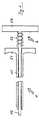
Bei dem in Figur 1 dargestellten Ausführungsbeispielist das Arbeitselement des Instruments eine Klemme,die im nicht betätigten Zustand geschlossen ist, und dieinsbesondere in Art einer Buldoc-Klemme ausgebildet ist.In the embodiment shown in Figure 1the working element of the instrument is a clamp,which is closed when not operated, and whichis designed in particular in the manner of a Buldoc clamp.
Der in Fig. 1 dargestellte Einführungs- und Betätigungsteilbesteht aus einem stabförmigen Teil 1, der in denKanal eines nicht dargestellten Einsetzinstruments, wieeines Trokars einsetzbar ist, und einem proximalen Bedienteil2. Der stabförmige Teil 1 wiederum besteht aus einemzylindrischen Rohr 11 und einem Stab 12, der in dem Rohr11 in Richtung seiner Längsachse verschiebbar ist.DerBedienteil 2 besteht aus zwei Handgriffen 21 und 22, vondenen der Handgriff 21 mit dem Rohr 11 und der Handgriff22 mit dem Stab 12 verbunden ist. Zwischen die Handgriffe21 und 22 ist eine Feder 23 eingesetzt.The insertion and actuation part shown in Fig. 1consists of a rod-shaped part 1, which in theChannel of an insertion instrument, not shown, such asa trocar can be used, and a
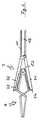
In Fig. 2 sind jeweils gleiche oder entsprechendeTeile mit den selben Bezugszeichen bezeichnet, so daß aufeine erneute Vorstellung verzichtet wird, und lediglichdie Abweichungen des in dieser Figur dargestellten Ausführungsbeispiels.2 are the same or correspondingParts labeled with the same reference numerals, so that ona new presentation is dispensed with, and onlythe deviations of the embodiment shown in this figure.
Gemäß Fig. 2weist derVerbindungsmechanismus eine am stabförmigen Teil 1 angebrachte Zange 7 auf, deren durch Zangenelemente 71 und 72gebildetes Zangenmaul durch Betätigung des Bedienteils 2geöffnet und geschlossen werden können. Die Zangenelemente71 und 72 haben an den Greifflächen die gleiche Zahnung 73wie die gegriffenen Flächen 74 der Buldoc-Klemme 4, diebei der gezeigten Modifikation einstückig ausgeführt ist.Die Zahnung 73 ist als Karo ausgebildet ist, dessen einzelneZähne pyramidenförmig gestaltet sind. Anstelle derdargestellten Feder 53 kann die Buldoc-Klemme auch eineSchenkelfeder haben.2points theConnection mechanism attached to the rod-shaped part 1
Vorstehend ist die Erfindungohne Beschränkung des allgemeinen Erfindungsgedankensbeschrieben worden, wie er den Ansprüchen entnehmbarist.Above is the inventionwithout restricting the general idea of the inventionhave been described as it can be found in the claimsis.
Claims (14)
- Instrument for use in endoscopic operations on the human or animal body,comprisingwith said operating element (4) and said insertion and actuating component (1,2) being connected via a connecting mechanism in such a wayan insertion instrument (11) adapted for being inserted into the human oranimal body and presenting a duct, andan operating instrument (12) adapted to be introduced through said ductof said insertion instrument into the body andconsisting at least of a distally disposed operating element (4) andan elongate insertion and actuating component (1, 2) passing throughsaid duct and connecting said operating element (4) to the proximal regionof the instrument such that said operating element (4) may be operatedfrom the proximal region,
that said operating element (4) may be detached from said insertion and actuatingcomponent (1, 2) inside the body such that said actuating component (2)may be removed from said duct without said operating element,
that said operating element (4) remains at least in one functional state afterdetachment from said insertion and actuating component (1, 2), and
after re-insertion of said insertion and actuating component (1, 2) into the ductof said insertion instrument, said operating element (4) is adapted for being reconnectedto this instrument and subsequently removed through said duct,
wherein said connecting mechanism presents forceps (7) mounted on said insertionand actuating component (1, 2), whose forceps jaws may be openedand closed by actuation of said actuating component (2),
characterised in that the forceps elements (71, 72) and the engaged surfaces(74) of said operating element (4) present the same toothing (73) that ensuresthat said operating element (4) will be engaged by said forceps (7) in a wayprotected from sliding and twisting. - Instrument according to Claim 1,
characterised in that, after detachment from said insertion and actuatingcomponent (1, 2), said operating element (4) may assume at least two stablefunctional states. - Instrument according to any of the Claims 1 or 2,
characterised in that said connecting mechanism is capable of transmitting atleast axial tensile or pressure forces to said operating element (4). - Instrument according to any of the Claims 1 to 3,
characterised in that said connecting mechanism presents provisions counteractingan unintentional interruption of the connection. - Instrument according to any of the Claims 1 to 4,
characterised in that said insertion and actuating component (1, 2) consists ofa rod-shaped part (12), that is adapted for being introduced into the duct ofsaid insertion instrument (11), and of a proximal actuating component (2). - Instrument according to Claim 5,
characterised in that said proximal actuating component (2) is adapted for detachmentfrom said rod-shaped part (12). - Instrument according to Claim 5 or 6,
characterised in that said operating element (4) is rigidified by retraction intosaid insertion component (1). - Instrument according to any of the Claims 1 to 7,
characterised in that said operating element (4) comprises at least one actuatorelement (53) consisting of a shape memory material. - Instrument according to any of the Claims 1 to 8,
characterised in that said operating element (4) is a clamp that is closed inthe non-operated condition. - Instrument according to Claim 9,
characterised in that said clamp is designed in the manner of a Buldoc clampand particularly in the form of an integral Buldoc clamp. - Instrument according to any of the Claims 1 to 8,
characterised in that said operating element (4) is a retractor. - Instrument according to Claim 11,
characterised in that said retractor is closed by pulling it into said insertioncomponent. - Instrument according to Claim 11 or 12,
characterised in that said retractor is a liver retractor. - Instrument according to any of the Claims 1 to 13,
characterised in that said toothing (73) is designed in the form of a square orlozenge whose individual teeth present a pyramid shape in particular.
Priority Applications (1)
| Application Number | Priority Date | Filing Date | Title |
|---|---|---|---|
| EP01116327AEP1174090B1 (en) | 1994-05-04 | 1995-05-04 | Clip for use in endoscopic operations |
Applications Claiming Priority (3)
| Application Number | Priority Date | Filing Date | Title |
|---|---|---|---|
| DE4415521ADE4415521C2 (en) | 1994-05-04 | 1994-05-04 | Instrument for use in endoscopic procedures |
| DE4415521 | 1994-05-04 | ||
| PCT/DE1995/000577WO1995030376A2 (en) | 1994-05-04 | 1995-05-04 | Instrument for use in endoscopic operations |
Related Child Applications (1)
| Application Number | Title | Priority Date | Filing Date |
|---|---|---|---|
| EP01116327ADivisionEP1174090B1 (en) | 1994-05-04 | 1995-05-04 | Clip for use in endoscopic operations |
Publications (2)
| Publication Number | Publication Date |
|---|---|
| EP0758214A1 EP0758214A1 (en) | 1997-02-19 |
| EP0758214B1true EP0758214B1 (en) | 2002-02-20 |
Family
ID=6517139
Family Applications (2)
| Application Number | Title | Priority Date | Filing Date |
|---|---|---|---|
| EP01116327AExpired - LifetimeEP1174090B1 (en) | 1994-05-04 | 1995-05-04 | Clip for use in endoscopic operations |
| EP95917265AExpired - LifetimeEP0758214B1 (en) | 1994-05-04 | 1995-05-04 | Instrument for use in endoscopic operations |
Family Applications Before (1)
| Application Number | Title | Priority Date | Filing Date |
|---|---|---|---|
| EP01116327AExpired - LifetimeEP1174090B1 (en) | 1994-05-04 | 1995-05-04 | Clip for use in endoscopic operations |
Country Status (5)
| Country | Link |
|---|---|
| US (1) | US6210418B1 (en) |
| EP (2) | EP1174090B1 (en) |
| JP (1) | JP3407743B2 (en) |
| DE (3) | DE4415521C2 (en) |
| WO (1) | WO1995030376A2 (en) |
Families Citing this family (154)
| Publication number | Priority date | Publication date | Assignee | Title |
|---|---|---|---|---|
| DE19635354A1 (en)* | 1996-05-10 | 1997-11-20 | Storz Karl Gmbh & Co | Suture aid device for minimally invasive surgical procedures |
| EP0902649B1 (en) | 1996-05-10 | 2001-09-05 | Karl Storz GmbH & Co. KG | Suturing aid |
| DE19750008C1 (en)* | 1997-11-12 | 1999-06-02 | Lothar Dipl Ing Schilder | Surgical instrument for gasless minimally invasive surgery |
| DE29811510U1 (en) | 1998-06-27 | 1998-10-08 | Tenckhoff, Dirk, 36100 Petersberg | Device for handling clips, in particular for microsurgery |
| ES2140355B1 (en)* | 1998-08-06 | 2000-10-16 | Agospi S L | ORGAN, TISSUE AND / OR VISCER SEPARATOR INSTRUMENT. |
| US8758400B2 (en) | 2000-01-05 | 2014-06-24 | Integrated Vascular Systems, Inc. | Closure system and methods of use |
| US9579091B2 (en) | 2000-01-05 | 2017-02-28 | Integrated Vascular Systems, Inc. | Closure system and methods of use |
| DE60144328D1 (en) | 2000-09-08 | 2011-05-12 | Abbott Vascular Inc | Surgical clamp |
| US6623510B2 (en) | 2000-12-07 | 2003-09-23 | Integrated Vascular Systems, Inc. | Closure device and methods for making and using them |
| US8690910B2 (en) | 2000-12-07 | 2014-04-08 | Integrated Vascular Systems, Inc. | Closure device and methods for making and using them |
| US6695867B2 (en) | 2002-02-21 | 2004-02-24 | Integrated Vascular Systems, Inc. | Plunger apparatus and methods for delivering a closure device |
| US6723109B2 (en) | 2001-02-07 | 2004-04-20 | Karl Storz Endoscopy-America, Inc. | Deployable surgical clamp with delivery/retrieval device and actuator |
| CA2451102C (en)* | 2001-07-09 | 2009-09-15 | Tyco Healthcare Group Lp | Right angle clip applier apparatus and method |
| US20030229368A1 (en)* | 2002-04-22 | 2003-12-11 | Viola Frank J. | Endoscopic surgical clip |
| EP2813186B1 (en) | 2002-04-22 | 2020-01-01 | Covidien LP | Endoscopic surgical clip |
| IES20030424A2 (en) | 2002-06-04 | 2003-12-10 | Robert Stevenson | Blood vessel closure clip and delivery device |
| US8398656B2 (en) | 2003-01-30 | 2013-03-19 | Integrated Vascular Systems, Inc. | Clip applier and methods of use |
| US8202293B2 (en) | 2003-01-30 | 2012-06-19 | Integrated Vascular Systems, Inc. | Clip applier and methods of use |
| US20040193213A1 (en)* | 2003-03-11 | 2004-09-30 | Ernest Aranyi | Clip applying apparatus with curved jaws, and clip |
| EP1608272B1 (en) | 2003-03-11 | 2017-01-25 | Covidien LP | Clip applying apparatus with angled jaw |
| FR2873564B1 (en)* | 2004-07-27 | 2006-11-24 | Assist Publ Hopitaux De Paris | INSTRUMENT AND DEVICE FOR PARIETAL ANCHOR, IN PARTICULAR FOR LAPAROSCOPIC OR COELIOSCOPIC SURGERY |
| WO2006034403A2 (en) | 2004-09-23 | 2006-03-30 | Tyco Healthcare Group, Lp | Clip applying apparatus and ligation clip |
| EP2641548B1 (en) | 2004-10-08 | 2015-08-19 | Covidien LP | Endoscopic surgical clip applier |
| US8409222B2 (en) | 2004-10-08 | 2013-04-02 | Covidien Lp | Endoscopic surgical clip applier |
| US9763668B2 (en) | 2004-10-08 | 2017-09-19 | Covidien Lp | Endoscopic surgical clip applier |
| CA2809110A1 (en) | 2004-10-08 | 2006-04-20 | Tyco Healthcare Group Lp | Apparatus for applying surgical clips |
| US7819886B2 (en) | 2004-10-08 | 2010-10-26 | Tyco Healthcare Group Lp | Endoscopic surgical clip applier |
| US8313497B2 (en) | 2005-07-01 | 2012-11-20 | Abbott Laboratories | Clip applier and methods of use |
| US7738401B2 (en)* | 2005-10-20 | 2010-06-15 | At&T Intellectual Property I, L.P. | System and method for overlaying a hierarchical network design on a full mesh network |
| US20070173866A1 (en)* | 2006-01-23 | 2007-07-26 | Tyco Healthcare Group, Lp | Surgical hemostatic clip |
| DE202006002436U1 (en)* | 2006-02-16 | 2006-05-04 | Peter Lazic Gmbh | Clip applier |
| USD629101S1 (en) | 2006-03-24 | 2010-12-14 | Tyco Healthcare Group Lp | Surgical clip applier |
| USD625009S1 (en) | 2006-03-24 | 2010-10-05 | Tyco Healthcare Group Lp | Surgical clip applier |
| EP2015681B1 (en) | 2006-05-03 | 2018-03-28 | Datascope Corp. | Tissue closure device |
| US8556930B2 (en) | 2006-06-28 | 2013-10-15 | Abbott Laboratories | Vessel closure device |
| CA2605135C (en) | 2006-10-17 | 2014-12-30 | Tyco Healthcare Group Lp | Apparatus for applying surgical clips |
| ES2328882B1 (en)* | 2006-12-14 | 2010-09-16 | Universidad De Zaragoza | TUBULAR ORGAN FORCIPRESSION CLAMP ASSEMBLY FOR USE IN ENDOSCOPIC SURGERY. |
| EP2157920B1 (en) | 2007-03-26 | 2017-09-27 | Covidien LP | Endoscopic surgical clip applier |
| CN102327136B (en) | 2007-04-11 | 2014-04-23 | 柯惠Lp公司 | Surgical clip applier |
| US8133242B1 (en) | 2007-04-27 | 2012-03-13 | Q-Tech Medical Incorporated | Image-guided extraluminal occlusion |
| US20090210005A1 (en)* | 2008-02-19 | 2009-08-20 | Dinger Iii Fred B | Method and system for displacing hyoid bone |
| US9282965B2 (en)* | 2008-05-16 | 2016-03-15 | Abbott Laboratories | Apparatus and methods for engaging tissue |
| US20110208212A1 (en) | 2010-02-19 | 2011-08-25 | Zergiebel Earl M | Surgical clip applier |
| US8465502B2 (en) | 2008-08-25 | 2013-06-18 | Covidien Lp | Surgical clip applier and method of assembly |
| US8056565B2 (en) | 2008-08-25 | 2011-11-15 | Tyco Healthcare Group Lp | Surgical clip applier and method of assembly |
| US8585717B2 (en) | 2008-08-29 | 2013-11-19 | Covidien Lp | Single stroke endoscopic surgical clip applier |
| US8409223B2 (en) | 2008-08-29 | 2013-04-02 | Covidien Lp | Endoscopic surgical clip applier with clip retention |
| US8267944B2 (en) | 2008-08-29 | 2012-09-18 | Tyco Healthcare Group Lp | Endoscopic surgical clip applier with lock out |
| US9358015B2 (en) | 2008-08-29 | 2016-06-07 | Covidien Lp | Endoscopic surgical clip applier with wedge plate |
| US8398676B2 (en) | 2008-10-30 | 2013-03-19 | Abbott Vascular Inc. | Closure device |
| US9414820B2 (en) | 2009-01-09 | 2016-08-16 | Abbott Vascular Inc. | Closure devices, systems, and methods |
| US9173644B2 (en) | 2009-01-09 | 2015-11-03 | Abbott Vascular Inc. | Closure devices, systems, and methods |
| US9486191B2 (en) | 2009-01-09 | 2016-11-08 | Abbott Vascular, Inc. | Closure devices |
| US20100179589A1 (en) | 2009-01-09 | 2010-07-15 | Abbott Vascular Inc. | Rapidly eroding anchor |
| US20100185234A1 (en) | 2009-01-16 | 2010-07-22 | Abbott Vascular Inc. | Closure devices, systems, and methods |
| US20110054492A1 (en) | 2009-08-26 | 2011-03-03 | Abbott Laboratories | Medical device for repairing a fistula |
| US8734469B2 (en) | 2009-10-13 | 2014-05-27 | Covidien Lp | Suture clip applier |
| US9186136B2 (en) | 2009-12-09 | 2015-11-17 | Covidien Lp | Surgical clip applier |
| US8545486B2 (en) | 2009-12-15 | 2013-10-01 | Covidien Lp | Surgical clip applier |
| US8403945B2 (en) | 2010-02-25 | 2013-03-26 | Covidien Lp | Articulating endoscopic surgical clip applier |
| US8211121B1 (en) | 2010-03-06 | 2012-07-03 | Q-Tech Medical Incorporated | Methods and apparatus for image-guided extraluminal occlusion using clamping jaws |
| US20110224718A1 (en)* | 2010-03-10 | 2011-09-15 | Torgerson Clinton D | Surgical needle driver and method of making the same |
| US9433421B2 (en)* | 2010-03-12 | 2016-09-06 | Jms Co., Ltd. | Surgical tool for anastomosis |
| RO126740A2 (en) | 2010-04-02 | 2011-10-28 | Cătălin Eşanu | Endoscopic surgery instrument with detachable clamp, clamp-extractor and method for using the same |
| US8403946B2 (en) | 2010-07-28 | 2013-03-26 | Covidien Lp | Articulating clip applier cartridge |
| US8968337B2 (en) | 2010-07-28 | 2015-03-03 | Covidien Lp | Articulating clip applier |
| DE102010037468A1 (en)* | 2010-09-10 | 2012-03-15 | Aesculap Ag | Surgical clip |
| DE102010037949A1 (en)* | 2010-10-04 | 2012-04-05 | Aesculap Ag | Surgical clip |
| US9011464B2 (en) | 2010-11-02 | 2015-04-21 | Covidien Lp | Self-centering clip and jaw |
| US9186153B2 (en) | 2011-01-31 | 2015-11-17 | Covidien Lp | Locking cam driver and jaw assembly for clip applier |
| US9775623B2 (en) | 2011-04-29 | 2017-10-03 | Covidien Lp | Surgical clip applier including clip relief feature |
| US20130131697A1 (en) | 2011-11-21 | 2013-05-23 | Covidien Lp | Surgical clip applier |
| US9332976B2 (en) | 2011-11-30 | 2016-05-10 | Abbott Cardiovascular Systems, Inc. | Tissue closure device |
| US9364239B2 (en) | 2011-12-19 | 2016-06-14 | Covidien Lp | Jaw closure mechanism for a surgical clip applier |
| US9364216B2 (en) | 2011-12-29 | 2016-06-14 | Covidien Lp | Surgical clip applier with integrated clip counter |
| US9408610B2 (en) | 2012-05-04 | 2016-08-09 | Covidien Lp | Surgical clip applier with dissector |
| US9532787B2 (en) | 2012-05-31 | 2017-01-03 | Covidien Lp | Endoscopic clip applier |
| US9364209B2 (en) | 2012-12-21 | 2016-06-14 | Abbott Cardiovascular Systems, Inc. | Articulating suturing device |
| US9968362B2 (en) | 2013-01-08 | 2018-05-15 | Covidien Lp | Surgical clip applier |
| US9113892B2 (en) | 2013-01-08 | 2015-08-25 | Covidien Lp | Surgical clip applier |
| US9750500B2 (en) | 2013-01-18 | 2017-09-05 | Covidien Lp | Surgical clip applier |
| US9775624B2 (en) | 2013-08-27 | 2017-10-03 | Covidien Lp | Surgical clip applier |
| WO2015077356A1 (en) | 2013-11-19 | 2015-05-28 | Wheeler William K | Fastener applicator with interlock |
| US10702278B2 (en) | 2014-12-02 | 2020-07-07 | Covidien Lp | Laparoscopic surgical ligation clip applier |
| US9931124B2 (en) | 2015-01-07 | 2018-04-03 | Covidien Lp | Reposable clip applier |
| CN107205747B (en) | 2015-01-15 | 2020-09-08 | 柯惠有限合伙公司 | Reusable endoscopic surgical clip applier |
| US10292712B2 (en) | 2015-01-28 | 2019-05-21 | Covidien Lp | Surgical clip applier with integrated cutter |
| US10159491B2 (en) | 2015-03-10 | 2018-12-25 | Covidien Lp | Endoscopic reposable surgical clip applier |
| CN108348259B (en) | 2015-11-03 | 2020-12-11 | 柯惠有限合伙公司 | Endoscopic Surgical Fixture Applicator |
| US10702280B2 (en) | 2015-11-10 | 2020-07-07 | Covidien Lp | Endoscopic reposable surgical clip applier |
| US10905425B2 (en) | 2015-11-10 | 2021-02-02 | Covidien Lp | Endoscopic reposable surgical clip applier |
| US10390831B2 (en) | 2015-11-10 | 2019-08-27 | Covidien Lp | Endoscopic reposable surgical clip applier |
| CN108472044B (en) | 2016-01-11 | 2021-04-16 | 柯惠有限合伙公司 | endoscope-reserved surgical clip applier |
| AU2016388454A1 (en) | 2016-01-18 | 2018-07-19 | Covidien Lp | Endoscopic surgical clip applier |
| CA2958160A1 (en) | 2016-02-24 | 2017-08-24 | Covidien Lp | Endoscopic reposable surgical clip applier |
| EP4324410A3 (en)* | 2016-05-09 | 2024-04-17 | Boston Scientific Scimed, Inc. | Closure device with fixed jaw hook |
| WO2018027788A1 (en) | 2016-08-11 | 2018-02-15 | Covidien Lp | Endoscopic surgical clip applier and clip applying systems |
| CN109640844B (en) | 2016-08-25 | 2021-08-06 | 柯惠Lp公司 | Endoscopic Surgical Clip Appliers and Applicator Systems |
| US10639044B2 (en) | 2016-10-31 | 2020-05-05 | Covidien Lp | Ligation clip module and clip applier |
| US10660651B2 (en) | 2016-10-31 | 2020-05-26 | Covidien Lp | Endoscopic reposable surgical clip applier |
| US10610236B2 (en) | 2016-11-01 | 2020-04-07 | Covidien Lp | Endoscopic reposable surgical clip applier |
| US10426489B2 (en) | 2016-11-01 | 2019-10-01 | Covidien Lp | Endoscopic reposable surgical clip applier |
| US10492795B2 (en) | 2016-11-01 | 2019-12-03 | Covidien Lp | Endoscopic surgical clip applier |
| US10709455B2 (en) | 2017-02-02 | 2020-07-14 | Covidien Lp | Endoscopic surgical clip applier |
| US11116514B2 (en) | 2017-02-06 | 2021-09-14 | Covidien Lp | Surgical clip applier with user feedback feature |
| US10758244B2 (en) | 2017-02-06 | 2020-09-01 | Covidien Lp | Endoscopic surgical clip applier |
| US10660725B2 (en) | 2017-02-14 | 2020-05-26 | Covidien Lp | Endoscopic surgical clip applier including counter assembly |
| US10603038B2 (en) | 2017-02-22 | 2020-03-31 | Covidien Lp | Surgical clip applier including inserts for jaw assembly |
| US11583291B2 (en) | 2017-02-23 | 2023-02-21 | Covidien Lp | Endoscopic surgical clip applier |
| US10548602B2 (en) | 2017-02-23 | 2020-02-04 | Covidien Lp | Endoscopic surgical clip applier |
| US10675043B2 (en) | 2017-05-04 | 2020-06-09 | Covidien Lp | Reposable multi-fire surgical clip applier |
| US10722235B2 (en) | 2017-05-11 | 2020-07-28 | Covidien Lp | Spring-release surgical clip |
| US10898192B2 (en)* | 2017-06-15 | 2021-01-26 | Roberto Tapia Espriu | Adjustable pressure surgical clamp with releasable or integrated remote manipulator for laparoscopies |
| US10639032B2 (en) | 2017-06-30 | 2020-05-05 | Covidien Lp | Endoscopic surgical clip applier including counter assembly |
| US10660723B2 (en) | 2017-06-30 | 2020-05-26 | Covidien Lp | Endoscopic reposable surgical clip applier |
| US10675112B2 (en) | 2017-08-07 | 2020-06-09 | Covidien Lp | Endoscopic surgical clip applier including counter assembly |
| US10932790B2 (en) | 2017-08-08 | 2021-03-02 | Covidien Lp | Geared actuation mechanism and surgical clip applier including the same |
| US10863992B2 (en) | 2017-08-08 | 2020-12-15 | Covidien Lp | Endoscopic surgical clip applier |
| US10786262B2 (en) | 2017-08-09 | 2020-09-29 | Covidien Lp | Endoscopic reposable surgical clip applier |
| US10786263B2 (en) | 2017-08-15 | 2020-09-29 | Covidien Lp | Endoscopic reposable surgical clip applier |
| US10835341B2 (en) | 2017-09-12 | 2020-11-17 | Covidien Lp | Endoscopic surgical clip applier and handle assemblies for use therewith |
| US10653429B2 (en) | 2017-09-13 | 2020-05-19 | Covidien Lp | Endoscopic surgical clip applier |
| US10758245B2 (en) | 2017-09-13 | 2020-09-01 | Covidien Lp | Clip counting mechanism for surgical clip applier |
| US10835260B2 (en) | 2017-09-13 | 2020-11-17 | Covidien Lp | Endoscopic surgical clip applier and handle assemblies for use therewith |
| US10945734B2 (en) | 2017-11-03 | 2021-03-16 | Covidien Lp | Rotation knob assemblies and surgical instruments including the same |
| US10932791B2 (en) | 2017-11-03 | 2021-03-02 | Covidien Lp | Reposable multi-fire surgical clip applier |
| US11116513B2 (en) | 2017-11-03 | 2021-09-14 | Covidien Lp | Modular surgical clip cartridge |
| US10828036B2 (en) | 2017-11-03 | 2020-11-10 | Covidien Lp | Endoscopic surgical clip applier and handle assemblies for use therewith |
| US11376015B2 (en) | 2017-11-03 | 2022-07-05 | Covidien Lp | Endoscopic surgical clip applier and handle assemblies for use therewith |
| DE102017127290A1 (en) | 2017-11-20 | 2019-05-23 | Aesculap Ag | SURGICAL CLIP WITH BELLOW GUIDANCE SYSTEM |
| US10722236B2 (en) | 2017-12-12 | 2020-07-28 | Covidien Lp | Endoscopic reposable surgical clip applier |
| US10959737B2 (en) | 2017-12-13 | 2021-03-30 | Covidien Lp | Reposable multi-fire surgical clip applier |
| US10849630B2 (en) | 2017-12-13 | 2020-12-01 | Covidien Lp | Reposable multi-fire surgical clip applier |
| US10743887B2 (en) | 2017-12-13 | 2020-08-18 | Covidien Lp | Reposable multi-fire surgical clip applier |
| US11051827B2 (en) | 2018-01-16 | 2021-07-06 | Covidien Lp | Endoscopic surgical instrument and handle assemblies for use therewith |
| JP7348199B2 (en) | 2018-03-28 | 2023-09-20 | データスコープ コーポレイション | Device for atrial appendage exclusion |
| US10993721B2 (en) | 2018-04-25 | 2021-05-04 | Covidien Lp | Surgical clip applier |
| US10786273B2 (en) | 2018-07-13 | 2020-09-29 | Covidien Lp | Rotation knob assemblies for handle assemblies |
| US11259887B2 (en) | 2018-08-10 | 2022-03-01 | Covidien Lp | Feedback mechanisms for handle assemblies |
| US11219463B2 (en) | 2018-08-13 | 2022-01-11 | Covidien Lp | Bilateral spring for surgical instruments and surgical instruments including the same |
| US11246601B2 (en) | 2018-08-13 | 2022-02-15 | Covidien Lp | Elongated assemblies for surgical clip appliers and surgical clip appliers incorporating the same |
| US11278267B2 (en) | 2018-08-13 | 2022-03-22 | Covidien Lp | Latch assemblies and surgical instruments including the same |
| US11253267B2 (en) | 2018-08-13 | 2022-02-22 | Covidien Lp | Friction reduction mechanisms for handle assemblies |
| US11051828B2 (en) | 2018-08-13 | 2021-07-06 | Covidien Lp | Rotation knob assemblies and surgical instruments including same |
| US11033256B2 (en) | 2018-08-13 | 2021-06-15 | Covidien Lp | Linkage assembly for reusable surgical handle assemblies |
| US11344316B2 (en) | 2018-08-13 | 2022-05-31 | Covidien Lp | Elongated assemblies for surgical clip appliers and surgical clip appliers incorporating the same |
| US11147566B2 (en) | 2018-10-01 | 2021-10-19 | Covidien Lp | Endoscopic surgical clip applier |
| US11524398B2 (en) | 2019-03-19 | 2022-12-13 | Covidien Lp | Gear drive mechanisms for surgical instruments |
| US20220409240A1 (en)* | 2019-11-18 | 2022-12-29 | Scanlan International, Inc. | Tunneler instrument and method for placement of vascular grafts |
| JP7566781B2 (en)* | 2019-12-15 | 2024-10-15 | 株式会社シャルマン | Surgical Clips |
| US11779340B2 (en) | 2020-01-02 | 2023-10-10 | Covidien Lp | Ligation clip loading device |
| US11723669B2 (en) | 2020-01-08 | 2023-08-15 | Covidien Lp | Clip applier with clip cartridge interface |
| US12114866B2 (en) | 2020-03-26 | 2024-10-15 | Covidien Lp | Interoperative clip loading device |
| US12419648B2 (en) | 2022-09-26 | 2025-09-23 | Covidien Lp | Two-part fasteners for surgical clip appliers and surgical clip appliers for deploying the same |
Citations (1)
| Publication number | Priority date | Publication date | Assignee | Title |
|---|---|---|---|---|
| US5304183A (en)* | 1992-03-23 | 1994-04-19 | Laparomed Corporation | Tethered clamp retractor |
Family Cites Families (10)
| Publication number | Priority date | Publication date | Assignee | Title |
|---|---|---|---|---|
| DE640126C (en)* | 1934-07-29 | 1936-12-24 | Bruno Loewel Dr | Trocar |
| JPS5320957Y2 (en)* | 1973-11-14 | 1978-06-01 | ||
| US4337774A (en)* | 1978-06-14 | 1982-07-06 | Metatech Corporation | Micro surgical clip |
| JPS5542626A (en)* | 1978-09-20 | 1980-03-26 | Olympus Optical Co | Blocking device of coelom inside tubular portion |
| AR218795A1 (en)* | 1979-12-11 | 1980-06-30 | Derechinsky V | CLIP-HOLDING INSTRUMENT FOR THE "CLIPPING" OF BLOOD GLASSES |
| US4706668A (en)* | 1985-09-16 | 1987-11-17 | B & B Tools | Aneurysm clip pliers |
| US4957500A (en)* | 1988-10-27 | 1990-09-18 | Montefiore Hospital Association Of Western Pennsylvania | Normally closed clamp |
| US5171252A (en)* | 1991-02-05 | 1992-12-15 | Friedland Thomas W | Surgical fastening clip formed of a shape memory alloy, a method of making such a clip and a method of using such a clip |
| US5242456A (en)* | 1991-11-21 | 1993-09-07 | Kensey Nash Corporation | Apparatus and methods for clamping tissue and reflecting the same |
| JPH05277122A (en)* | 1992-04-03 | 1993-10-26 | Olympus Optical Co Ltd | Medical treatment implement |
- 1994
- 1994-05-04DEDE4415521Apatent/DE4415521C2/ennot_activeExpired - Lifetime
- 1995
- 1995-05-04WOPCT/DE1995/000577patent/WO1995030376A2/enactiveIP Right Grant
- 1995-05-04DEDE59511092Tpatent/DE59511092D1/ennot_activeExpired - Lifetime
- 1995-05-04EPEP01116327Apatent/EP1174090B1/ennot_activeExpired - Lifetime
- 1995-05-04JPJP52859395Apatent/JP3407743B2/ennot_activeExpired - Fee Related
- 1995-05-04DEDE59510067Tpatent/DE59510067D1/ennot_activeExpired - Lifetime
- 1995-05-04USUS08/732,460patent/US6210418B1/ennot_activeExpired - Lifetime
- 1995-05-04EPEP95917265Apatent/EP0758214B1/ennot_activeExpired - Lifetime
Patent Citations (1)
| Publication number | Priority date | Publication date | Assignee | Title |
|---|---|---|---|---|
| US5304183A (en)* | 1992-03-23 | 1994-04-19 | Laparomed Corporation | Tethered clamp retractor |
Also Published As
| Publication number | Publication date |
|---|---|
| US6210418B1 (en) | 2001-04-03 |
| DE59511092D1 (en) | 2008-05-15 |
| EP0758214A1 (en) | 1997-02-19 |
| DE4415521C2 (en) | 2003-01-30 |
| WO1995030376A2 (en) | 1995-11-16 |
| EP1174090A3 (en) | 2003-10-29 |
| DE59510067D1 (en) | 2002-03-28 |
| JPH10503390A (en) | 1998-03-31 |
| EP1174090A2 (en) | 2002-01-23 |
| WO1995030376A3 (en) | 1995-12-07 |
| JP3407743B2 (en) | 2003-05-19 |
| DE4415521A1 (en) | 1995-11-09 |
| EP1174090B1 (en) | 2008-04-02 |
Similar Documents
| Publication | Publication Date | Title |
|---|---|---|
| EP0758214B1 (en) | Instrument for use in endoscopic operations | |
| DE60211044T2 (en) | Implantable surgical clip with a delivery / retrieval device and operating element | |
| DE19704580C2 (en) | Surgical thread cutter | |
| DE69733648T2 (en) | METHOD FOR ATTACHING DEFORMABLE TERMINALS | |
| EP0513471A2 (en) | Surgical instrument | |
| WO2000067642A2 (en) | Retractor for use in endoscopic surgery | |
| DE3733194A1 (en) | INSTRUMENT FOR HOLDING SURGICAL NEEDLES | |
| DE3741879A1 (en) | ENDOSCOPIC INSTRUMENT | |
| EP0860148A2 (en) | Bayonet coupling for the releasable connection of two tubular-shaft instruments or two parts of an instrument | |
| WO2000051506A1 (en) | Instrument for cutting biological and notably human tissue | |
| WO2004078046A1 (en) | Medical equipment for creating a surgical space for oral surgery | |
| DE4324254C1 (en) | Surgical instrument for endoscopic surgery | |
| DE9203041U1 (en) | Laparoscopic needle holder | |
| DE4412171A1 (en) | Surgical instrument for endoscopy | |
| EP1185206B1 (en) | Medical gripping instrument | |
| WO1998003121A1 (en) | Trocar sheath for endoscopic use | |
| DE19700474A1 (en) | Surgical instrument | |
| DE60128406T2 (en) | AUXILIARY TONGUE FOR MANUALLY SUPPORTED LAPARASCOPIC SURGERY | |
| DE10224500A1 (en) | Medical gripping and / or holding instrument | |
| EP3155973A1 (en) | Biopsy forceps | |
| DE202009003255U1 (en) | Trocar guide sleeve and trocar system | |
| DE19719090A1 (en) | Minimal invasive surgical instrument | |
| DE4216874C1 (en) | ||
| DE10145107A1 (en) | Filling stick for endoscopes | |
| DE10222042B3 (en) | Handle arrangement for a medical instrument and such a medical instrument |
Legal Events
| Date | Code | Title | Description |
|---|---|---|---|
| PUAI | Public reference made under article 153(3) epc to a published international application that has entered the european phase | Free format text:ORIGINAL CODE: 0009012 | |
| 17P | Request for examination filed | Effective date:19961126 | |
| AK | Designated contracting states | Kind code of ref document:A1 Designated state(s):DE FR GB IT | |
| RBV | Designated contracting states (corrected) | Designated state(s):DE FR GB IT | |
| 17Q | First examination report despatched | Effective date:19980603 | |
| APAB | Appeal dossier modified | Free format text:ORIGINAL CODE: EPIDOS NOAPE | |
| APAB | Appeal dossier modified | Free format text:ORIGINAL CODE: EPIDOS NOAPE | |
| APBJ | Interlocutory revision of appeal recorded | Free format text:ORIGINAL CODE: EPIDOS IRAPE | |
| GRAG | Despatch of communication of intention to grant | Free format text:ORIGINAL CODE: EPIDOS AGRA | |
| RAP1 | Party data changed (applicant data changed or rights of an application transferred) | Owner name:ERBENGEMEINSCHAFT DR. H.C. KARL STORZ, VERTRETEN D | |
| RIN1 | Information on inventor provided before grant (corrected) | Inventor name:CUSCHIERI, ALFRED Inventor name:STORZ, KARL | |
| GRAG | Despatch of communication of intention to grant | Free format text:ORIGINAL CODE: EPIDOS AGRA | |
| GRAH | Despatch of communication of intention to grant a patent | Free format text:ORIGINAL CODE: EPIDOS IGRA | |
| GRAH | Despatch of communication of intention to grant a patent | Free format text:ORIGINAL CODE: EPIDOS IGRA | |
| GRAH | Despatch of communication of intention to grant a patent | Free format text:ORIGINAL CODE: EPIDOS IGRA | |
| REG | Reference to a national code | Ref country code:GB Ref legal event code:IF02 | |
| GRAA | (expected) grant | Free format text:ORIGINAL CODE: 0009210 | |
| AK | Designated contracting states | Kind code of ref document:B1 Designated state(s):DE FR GB IT | |
| REF | Corresponds to: | Ref document number:59510067 Country of ref document:DE Date of ref document:20020328 | |
| GBT | Gb: translation of ep patent filed (gb section 77(6)(a)/1977) | Effective date:20020407 | |
| ET | Fr: translation filed | ||
| PLBE | No opposition filed within time limit | Free format text:ORIGINAL CODE: 0009261 | |
| STAA | Information on the status of an ep patent application or granted ep patent | Free format text:STATUS: NO OPPOSITION FILED WITHIN TIME LIMIT | |
| 26N | No opposition filed | Effective date:20021121 | |
| PGFP | Annual fee paid to national office [announced via postgrant information from national office to epo] | Ref country code:GB Payment date:20140425 Year of fee payment:20 | |
| PGFP | Annual fee paid to national office [announced via postgrant information from national office to epo] | Ref country code:DE Payment date:20140424 Year of fee payment:20 Ref country code:IT Payment date:20140428 Year of fee payment:20 | |
| PGFP | Annual fee paid to national office [announced via postgrant information from national office to epo] | Ref country code:FR Payment date:20140521 Year of fee payment:20 | |
| REG | Reference to a national code | Ref country code:DE Ref legal event code:R071 Ref document number:59510067 Country of ref document:DE | |
| REG | Reference to a national code | Ref country code:GB Ref legal event code:PE20 Expiry date:20150503 | |
| PG25 | Lapsed in a contracting state [announced via postgrant information from national office to epo] | Ref country code:GB Free format text:LAPSE BECAUSE OF EXPIRATION OF PROTECTION Effective date:20150503 |