EP0757351B1 - Computer frame structure with modular housings - Google Patents
Computer frame structure with modular housingsDownload PDFInfo
- Publication number
- EP0757351B1 EP0757351B1EP96109263AEP96109263AEP0757351B1EP 0757351 B1EP0757351 B1EP 0757351B1EP 96109263 AEP96109263 AEP 96109263AEP 96109263 AEP96109263 AEP 96109263AEP 0757351 B1EP0757351 B1EP 0757351B1
- Authority
- EP
- European Patent Office
- Prior art keywords
- drive
- drives
- modular drive
- library
- modular
- Prior art date
- Legal status (The legal status is an assumption and is not a legal conclusion. Google has not performed a legal analysis and makes no representation as to the accuracy of the status listed.)
- Expired - Lifetime
Links
- 238000001816coolingMethods0.000claimsdescription5
- 230000003287optical effectEffects0.000claimsdescription4
- 230000008439repair processEffects0.000description15
- 238000000034methodMethods0.000description14
- 230000008859changeEffects0.000description6
- 238000004891communicationMethods0.000description3
- 238000005516engineering processMethods0.000description3
- 230000004888barrier functionEffects0.000description2
- 238000012546transferMethods0.000description2
- 230000009471actionEffects0.000description1
- 238000012937correctionMethods0.000description1
- 230000001351cycling effectEffects0.000description1
- 239000012526feed mediumSubstances0.000description1
- 230000002452interceptive effectEffects0.000description1
- 238000012423maintenanceMethods0.000description1
- 230000004048modificationEffects0.000description1
- 238000012986modificationMethods0.000description1
- 230000008569processEffects0.000description1
- 230000001629suppressionEffects0.000description1
- 230000001052transient effectEffects0.000description1
- 230000000007visual effectEffects0.000description1
- 230000003245working effectEffects0.000description1
Images


Classifications
- G—PHYSICS
- G11—INFORMATION STORAGE
- G11B—INFORMATION STORAGE BASED ON RELATIVE MOVEMENT BETWEEN RECORD CARRIER AND TRANSDUCER
- G11B33/00—Constructional parts, details or accessories not provided for in the other groups of this subclass
- G11B33/12—Disposition of constructional parts in the apparatus, e.g. of power supply, of modules
- G11B33/125—Disposition of constructional parts in the apparatus, e.g. of power supply, of modules the apparatus comprising a plurality of recording/reproducing devices, e.g. modular arrangements, arrays of disc drives
- G11B33/127—Mounting arrangements of constructional parts onto a chassis
- G11B33/128—Mounting arrangements of constructional parts onto a chassis of the plurality of recording/reproducing devices, e.g. disk drives, onto a chassis
- G—PHYSICS
- G11—INFORMATION STORAGE
- G11B—INFORMATION STORAGE BASED ON RELATIVE MOVEMENT BETWEEN RECORD CARRIER AND TRANSDUCER
- G11B33/00—Constructional parts, details or accessories not provided for in the other groups of this subclass
- G11B33/14—Reducing influence of physical parameters, e.g. temperature change, moisture, dust
- G11B33/1406—Reducing the influence of the temperature
- G11B33/1413—Reducing the influence of the temperature by fluid cooling
- G11B33/142—Reducing the influence of the temperature by fluid cooling by air cooling
- G—PHYSICS
- G11—INFORMATION STORAGE
- G11B—INFORMATION STORAGE BASED ON RELATIVE MOVEMENT BETWEEN RECORD CARRIER AND TRANSDUCER
- G11B15/00—Driving, starting or stopping record carriers of filamentary or web form; Driving both such record carriers and heads; Guiding such record carriers or containers therefor; Control thereof; Control of operating function
- G11B15/675—Guiding containers, e.g. loading, ejecting cassettes
- G11B15/68—Automatic cassette changing arrangements; automatic tape changing arrangements
- G—PHYSICS
- G11—INFORMATION STORAGE
- G11B—INFORMATION STORAGE BASED ON RELATIVE MOVEMENT BETWEEN RECORD CARRIER AND TRANSDUCER
- G11B17/00—Guiding record carriers not specifically of filamentary or web form, or of supports therefor
- G11B17/22—Guiding record carriers not specifically of filamentary or web form, or of supports therefor from random access magazine of disc records
Definitions
- This inventionpertains to a new computer frame structure with modular housings.
- the structureis particularly adaptable to a multiple drive library computer system.
- repair of a failed drivemay occur while one or more good drives in the library system remain online. In this manner, a host may have continual and uninterrupted access to information stored within the library.
- frame structure with modular housings disclosed hereinis especially advantageous in removable media type multiple drive library computer systems, it may also be adapted to other multiple component computer systems as well.
- the computer frame structure with modular housings disclosed hereinmay be used in conjunction with the I/O Bus and system and method of Online Drive Repair disclosed herein, and in U.S. patents 5,881,249 and 5,870,630 filed concurrently on July 31, 1995.
- the first component to fail due to excessive useis often a storage drive.
- a storage drivefails, the library undergoes a period of down time while the drive is repairedand/or replaced. During this down time, a host (whether it be a UNIX work station, PC network server or otherwise) cannot access any of the information contained within the library.
- the RAID technologyinvolves a method of reconstructing data which is lost in the event of a drive's failure.
- Datais stored in a redundant array of non-removable media type drives, such that when a failed drive is replaced, an error-correction operation can be applied to the data blocks of the remaining storage drives in the redundant array so that the data which was lost can be reconstructed.
- the RAID methodhelps to minimize library down time, the method is not applicable to removable media type libraries. In a removable media type library, failure of a drive does not result in loss of data. It only results in loss of access to data.
- a hot repairable systemstorage drives are guided on rails into hot repair sockets.
- a failed drivemay be removed from its socket without notification to the library system or a host.
- a system of long and short pinsis used to incrementally disconnect power to the drive, to notify the library system and the host that the drive is no longer available, and to make the necessary changes in system parameters to keep the library system online.
- there is a barrier to implementing hot repair technology in a removable media type libraryThe barrier exists due to the requirement of a removable media type library that the media inserting faces of its storage drives face a robotic media inserter. In order to keep such a system online, it is necessary to remove storage drives by pulling them away from the robotic inserter.
- the electrical connection faces of the storage drives(which in standard drives are opposite their media inserting faces) must be free of blockage (sockets, circuit boards, pins, etc.).
- a storage drivewould need to be constructed wherein its media inserting face and electrical connection face were on adjacent sides, rather than on opposite sides. This is an added expense which is unnecessary in view of the online repairable system and method of online drive repair disclosed herein.
- EP 0 289 986 Adescribes an apparatus for the handling of pre-recorded television programs which comprises a filing cabinet served by an arm, adapted to grasp cartridges of recorded tapes, displaceable along two first perpendicular axis to transfer the cartridges from the filing cabinet to an assembly of recording/playing devices for magnetic tapes which are arranged adjacent to the filing cabinet.
- EP 0 242 970 Adescribes a modular subsystem including a housing array for containing a plurality of hardware element modules, each being connected to a separate source of primary facility power. Each module is self-aligning and blind-mateable with the housing and may be installed and removed without tools, without disturbing the electrical cabling, and automatically by a maintenance robot.
- a removable media type libraryis provided in which library down time is eliminated.
- a new frame structure for a multi-drive library computer systemhaving a plurality of storage drives and a number of electronic and mechanical sub-systems, each drive having a media-inserting face abutting a robotic media inserter, and an electrical connection face opposite to said media-inserting face.
- the frame structurecomprises a primary frame structure which contains a number of said subsystems, and one or more modular drive housings, attachable to said primary frame structure, in which are mounted one or more of said storage drives, wherein each of said modular drive housings, and the drive(s) mounted therein, is removable from said primary frame as a unit.
- the new frame structure with modular housingsallows good drives in a multiple drive library computer system to remain online, and accessible to a host, during the repair of one or more failed drives.
- Library down timeis thereby significantly reduced, or in the case of a removable media type library, library down time is eliminated.
- a multiple drive library computer system 44is pictured in FIGS. 1, 2 & 4, which may generally comprise an I/O bus 122, generally operating under a SCSI protocol, said bus 122 comprising a primary I/O bus 94 and a plurality of secondary I/O buses 96, 98, 100, 102, 104, 106, pigtailed to said primary bus 94, a plurality of storage drives 50, 52, 54, 56, 58, 60 connected to said plurality of secondary I/O buses (96, 98...), and a library controller 36, connected to said primary I/O bus 94, said controller 36 comprising firmware to communicate with a host computer 48 via said I/O bus 122, and firmware to communicate with said storage drives (50, 52%) via a general purpose bus 62.
- I/O bus 122generally operating under a SCSI protocol
- said bus 122comprising a primary I/O bus 94 and a plurality of secondary I/O buses 96, 98, 100, 102, 104, 106
- the library system 44comprises six computer storage drives (50, 52).
- the storage drivesare housed in six modular housings 20, 22, 24, 26, 28, 30, each of which can hold one full-height drive (50, 52).
- the drives (50, 52%)are connected to other library system components via an internal I/O bus 122.
- This bus 122generally operates under a Small Computer Systems Interface protocol (SCSI protocol). See FIG. 2.
- the internal I/O bus 122further comprises a primary I/O bus 94, and a plurality of secondary I/O buses (96, 98%), pigtailed to said primary I/O bus 94. All storage drives (50, 52%) are connected to the I/O bus 122 via the secondary (pigtailed) buses (96, 98).
- the primary I/O bus 94is shown running between connectors 78, 80, 82, 84, 86, 88 on upper 32 and lower 34 interposer PC boards. Some sections of the primary I/O bus 94 may comprise traces 112, 114, 118, 120 etched into the interposer boards 32, 34. Other sections 108, 110, 116 of the primary I/O bus 94 may comprise standard SCSI cabling.
- a general purpose bus 62is connected between the storage drives (50, 52%) and the library controller 36. While the primary function of the SCSI protocol I/O bus 122 is data transfer, the primary function of the general purpose bus is communication between the storage drives (50, 52%) and the library controller 36.
- FIG. 4shows the rear face of a storage drive 60.
- the storage drives (50, 52%) shownare optical, removable media type drives. See. FIG. 5.
- Each drive (50, 52%)has a media inserting face 300 abutting a robotic media inserter 40.
- the media inserting face 300 of a drive 60is shown in FIG. 5.
- a typical placement of a robotic media inserter 40is best seen in FIG. 4.
- Robotic media inserters for optical, removable media type drivesare disclosed in U.S. patent #5,010,536 and U.S. patent 5,730,031 filed August 24, 1994.
- Opposite said media inserting faces 300, the drives (50, 52...)have electrical connection faces 302.
- Each electrical connection face 302has a connector (e.g. connector 304 on drive 60 as shown in FIG. 4) for connecting a secondary I/O bus (96, 98...) and a connector to which a power cable may be attached (not shown).
- the primary I/O bus 94is attached to a library controller 36 (or autochanger controller) at connector 76.
- a general purpose bus 62is also attached to the controller.
- the controller 36comprises firmware which allows it to communicate with the storage drives (50, 52%) via the general purpose bus 62.
- the controller 36also comprises firmware which allows it to communicate with a host 48 (whether it be a UNIX work station, PC network server or otherwise) via the SCSI protocol I/O bus 122.
- the controller 36is responsive to host commands and may perform such operations as keeping track of the location of removable media cartridges, moving removable media cartridges, and relaying its successes and/or failures to the host 48.
- the controller 36may also process and carry out library commands.
- the controller 36may also be responsible for changing drive states, in the preferred embodiment, this is left to the host 48.
- the controller 36contains a microprocessor, the controller is a component which may only speak when spoken to - it cannot initiate action.
- the controller 36may also comprise firmware which allows it to enable or disable power to one or more storage drives (50, 52). In so enabling or disabling power, a system for suppressing power transients is used. This power transient suppression system is similar to that disclosed in U.S. patent 5,587,687 filed October 31, 1994. Alternatively, switches (not shown) could be used to enable or disable power to the drives (50, 52).
- An LED 64, 66, 68, 70, 72, 74is mounted next to each drive (50, 52).
- the LEDs (64, 66%)are mounted on the interposer boards 32, 34.
- the LEDs (64, 66%)may be controlled by either the library system 44 or the host 48 to serve as a visual indication of the status of a drive (50, 52%) to a service technician.
- a lighted LED (64, 66%)could signify "power on”
- an unlighted LED (64, 66%)could signify “power off”
- a flashing LED (64, 66%)could signify a powered drive in an "Offline_failed" state (this state will soon be described in more detail).
- a SCSI repeater board 46is also connected to the primary I/O bus 94 via connector 90. See FIG. 2.
- the repeater board 46is contained within repeater board enclosure 38.
- the repeater board 46is responsible for electrically isolating I/O bus 122 from the outside world. It protects the protocol used on bus 122 from being reconfigured by a component outside the library system 44, such as the host 48.
- the repeater board 46provides an input 128 for an external SCSI bus 92 which connects the library system 44 to a host 48.
- the host 48may be a UNIX work station, PC network server, or other host device as previously mentioned.
- the repeater board 46is especially important in the library system 44 outlined above due to the configuration of the I/O bus 122.
- a typical SCSI systemcomprises several components which are daisy-chained together. Thus, removing one component from the system causes a break in the bus which can shut down communication with many components. Since a purpose of this invention was to achieve an online repairable system, it became necessary to construct a cable which allowed for removal of a single component without disabling the entire bus. To achieve the desired result, storage drives (50, 527) are pigtailed to a primary I/O bus 94 via secondary I/O buses (96, 98).
- any secondary I/O bus(96, 98%) may be removed from the system without breaking the primary I/O bus 94 and interfering with communication between other system components via the primary I/O bus 94.
- SCSI protocoldictates that a bus 122 may comprise no more than six feet of cable, and a stub (such as pigtails 96, 98...) off of a primary bus 94 may be no longer than 100mm.
- the primary bus 94comprises approximately 1,5748 mm (62") of cable, and each pigtail (96, 98...) comprises approximately 30,48 cm (12") of cable.
- the total cable lengthis 3,4036 m (11'2").
- the I/O bus 122must be isolated from the outside world, and cannot be subject to reconfiguration.
- the repeater board 46serves this important function.
- the storage drives (50, 52%)are mounted to the library system frame structure 42 via modular drive housings (20, 22).
- FIG. 5shows a modular drive housing 30 removed from the library system 44.
- Each modular drive housing (20, 227)comprises its own cooling fan 310, 312, 314, 316, 318 & 320, and a handle 330, 332, 334, 336, 338 & 340 for removing it from the library system 44. See also, FIG. 4.
- Removal of a modular drive housing (20, 22%)is accomplished by first disconnecting any cabling extending from said modular housing (20, 22%) (such as I/O bus cables (96, 98%) and any power cables (not shown)). Since the electrical connection faces 302 of the drives (50, 52%) are not readily accessible while the drives (50, 52%) are mounted within a modular housing (20, 22%), cabling is disconnected at the interposer boards 32 & 34. As a consequence, secondary I/O buses (96, 98%) and portions of power cables will be removed with a modular housing (20, 22). Once cabling is disconnected, a modular housing 30 may be removed from the library system 44. Cabling is not shown in FIG. 5 so as not to interfere with a view of cooling fan 320 and handle 340.
- a modular housing (20, 22%)is removed by pulling the modular housing (20, 22%) away from the robotic media inserter 40. Handles (330, 332%) on the modular housings (20, 22%) facilitate their removal. By way of example, a modular housing 30, and the drive 60 mounted therein, are removed from the library system 44 as a unit in FIG. 5.
- the library system 44comprises twelve computer storage drives 150, 151, 152, 153, 154, 155, 156, 157, 158, 159, 160, 161.
- the twelve storage drives (150, 151%)are housed in the same six modular housings (20, 22%) identified above.
- Each modular housing (20, 22%)is designed so that it may, without any modification, hold either one full-height drive (50, 52%) or two half-height drives (150, 151).
- the drives (150, 151%)are connected to other system components via two internal I/O buses 222, 223.
- Each bus 222, 223generally operates under a SCSI protocol. See FIG. 3.
- Two internal I/O buses 222, 223are required in the twelve drive embodiment due to the SCSI limitation of eight component addresses on any particular bus.
- the first SCSI I/O bus 123comprises a primary bus 194 which includes several cable sections 208, 210, 212, 214 running between numerous connectors 176, 178, 180, 182, 191, and secondary buses 196, 198, 200.
- the second SCSI I/O bus 122comprises a primary bus 195 which again includes several cable sections 209, 213, 215 running between numerous connectors 184, 186, 188, 190, and secondary buses 202, 204, 206.
- Six of the twelve drives 150, 152, 154, 156, 158, 160are connected directly to secondary buses 196, 198, 200, 202, 204, 206.
- the remaining six drives 151, 153, 155, 157, 159, 161are connected to the SCSI I/O buses 222, 223 via the first six drives 150, 152, 154, 156, 158, 160 by way of several daisy-chained I/O buses 197, 199, 201, 203, 205, 207.
- a general purposes bus 162runs between the storage drives (150, 151%) and the library controller 36.
- Upper 132 and lower 134 PC interposer boardsagain provide mounts for bus connectors 178, 180, 182, 184, 186, 188 and power status LEDs 164-175.
- SCSI I/O buses 222, 223Due to the presence of two SCSI I/O buses 222, 223, two SCSI repeater boards are required 144, 146, one for each SCSI bus section.
- the host 48is connected to each of the repeater boards 144, 146 via a SCSI compatible cable.
- FIG. 6shows a rear view of the modular housing 30 of FIG. 5, wherein two half-height drives 160, 161 have been substituted for the one full-height drive 60.
- the media inserting faces 340 of the two half-height drives 160, 161are seen extending from the rear of the housing 30.
- FIG. 7shows a front perspective view of the components of FIG. 6.
- FIG. 8shows the two half-height drives 160, 161 and modular housing 30 of FIG. 6 in a disassembled fashion.
- the secondary I/O bus 206 and daisy-chained I/O bus 207which connect the storage drives shown 160, 161 to the primary I/O bus 195 are also shown in FIG. 8.
- FIG. 8reveals the three subsections 31, 33 & 35 which make up a modular housing 30.
- the failure of a drivemust be detected or instructed.
- the host's softwareprovides the means for detecting when a drive 160 has failed.
- the host 48may detect that a drive 160 has failed by several avenues. If the host 48 issues a command to the library to eject or load media to a drive 160 and receives a status code back from the library controller 36 indicating that the move operation was unsuccessful, the host 48 may assume that the drive 160 was at fault and is in need or repair.
- the host 48may also detect drive failure from a system level error indicating that the drive 160 is not functioning correctly.
- the host 48attempts to remove media from the failed drive, if any is present. After removing media, the host 48 informs the library controller 36 of the drive failure, and places the drive 160 in an "Offline_failed" state. (Note: a description of all of the various drive states is found in FIG. 10) The library controller 36 will store the drive state information, and will not allow further access to the failed drive 160 until its state is changed to "Online_good”. Drive states remain through power cycling.
- the failed drive 160may be serviced while the library system 44 remains online. It is therefore possible for the host 48 to continue accessing one or more good drives 150, 151, 152, 153, 154, 155, 156, 157, 158, 159 in an "Online_good” state, and retrieve information from media inserted into those drives, while the failed drive 160 is being repaired.
- a qualified service personaccesses the internal workings of the library (shown in FIG. 1).
- the service personwill know which drive is in an "Offline_failed" state by a flashing LED 174 near the drive 160. If, as assumed, a failed drive is mounted in a modular housing 30 containing two half-height drives 160, 161, both drives 160, 161 will need to be taken offline. However, only the failed drive 160 will actually be replaced.
- the host 48will place the good drive 161 which is commonly housed with the failed drive 160 in an "Offline_good_pending" state. The host 48 can then remove media from the commonly housed good drive 161 before placing it in an "Offline_good” state.
- the library controller 36With both drives 160, 161 in a drive pair offline, the library controller 36 will remove power to the drive pair. LEDs 174, 175 for the drive pair 160, 161 will indicate that power to the drives 160, 161 has been removed. At this point, the secondary I/O bus cable 206 may be safely disconnected from the primary I/O bus 195. Power cables to the drives (not shown) may also be disconnected at the PC interposer board 134 corresponding to the drives 160, 161 to be removed. In this manner, no interruption to the rest of the system 44 or the host 48 will occur.
- the modular housing 30 containing the failed drive 160may now be removed.
- the modular housing 30is removed by pulling it away from the robotic media inserter 40.
- the robotic media inserter 40is not interrupted as it continues to feed media to the library's good drives 150, 151, 152, 153, 154, 155, 156, 157, 158, 159.
- the removed modular housing 30is again mounted in its place, and cabling is reconnected to the removed drives 160, 161, the service technician sets the drive pair status to "Online_pending" via a switch (not shown) on the corresponding PC interposer board 134 which alerts the library controller 36.
- the library controller 36will then apply power to the drive pair 160, 161, and will also inform the host 48 of the drive state changes.
- the host 48then changes the states of the "Online_pending" drives to "Online_good”. All of the library's drives (150, 151%) are now accessible to the host 48.
- the host 48may only access a drive (150, 151%) when it is in an "Online_good” or “Offline_good_pending” state. At all other times, the library controller 36 will deny access to a drive (150, 151).
- the host 48changes drive states for the drives (150, 151%) via a SCSI "Write Buffer” command. Whenever the host 48 wants to change the state of a drive, it will simply issue the appropriate "Write Buffer” command. See FIG. 11 for specifications of the SCSI "Write Buffer” command.
- the library controller 36communicates to the host 48 via the SCSI "Unit Attention” condition. Whenever the library controller 36 wants to inform the host 48 of a change in the state(s) of the drive(s), it issues a "Unit Attention” condition on the next SCSI command sent by the host 48. Upon receiving the "Unit Attention” condition, the host 48 will send a SCSI "Read Buffer” command to determine the state change(s) of the drive(s). See FIG. 12 for specifications of the SCSI "Read Buffer” command.
- the library controller 36will respond with a "Unit Attention” condition to any command from the host 48 (except Inquiry) when there is a pending state change for one or more of the library's storage drives (150, 151).
- the host 48must then send a "Read Buffer” command to determine the state change.
- the "Unit Attention” conditionwill only be reported once per state change.
- the host 48may poll the library controller 36 with the "Read Buffer” command, if desired.
- the library controller 36will respond with an "Illegal Request” condition to any Move or Exchange command from the host 48 that involves a drive that is not in an "Online_good” or “Offline_good_pending” state.
Landscapes
- Automatic Disk Changers (AREA)
- Techniques For Improving Reliability Of Storages (AREA)
- Automatic Tape Cassette Changers (AREA)
Description
- This invention pertains to a new computer framestructure with modular housings. The structure isparticularly adaptable to a multiple drive library computersystem. With the newly invented frame structure withmodular housings disclosed herein, repair of a failed drivemay occur while one or more good drives in the librarysystem remain online. In this manner, a host may havecontinual and uninterrupted access to information storedwithin the library.
- Although the frame structure with modular housingsdisclosed herein is especially advantageous in removablemedia type multiple drive library computer systems, it mayalso be adapted to other multiple component computersystems as well.
- The computer frame structure with modular housingsdisclosed herein may be used in conjunction with the I/O Bus and system and method of Online Drive Repair disclosedherein, and in U.S. patents 5,881,249 and 5,870,630 filed concurrentlyon July 31, 1995.
- In a multiple drive library computer system, the firstcomponent to fail due to excessive use is often a storagedrive. Typically, when a storage drive fails, the libraryundergoes a period of down time while the drive isrepairedand/or replaced. During this down time, a host(whether it be a UNIX work station, PC network server orotherwise) cannot access any of the information containedwithin the library.
- Since loss of information access is unacceptable,efforts have been made to minimize library down time.These efforts include Redundant Array of Inexpensive Disks(RAID) and hot repair technologies.
- The RAID technology involves a method ofreconstructing data which is lost in the event of a drive'sfailure. Data is stored in a redundant array of non-removablemedia type drives, such that when a failed driveis replaced, an error-correction operation can be appliedto the data blocks of the remaining storage drives in theredundant array so that the data which was lost can bereconstructed. Although the RAID method helps to minimizelibrary down time, the method is not applicable to removable media type libraries. In a removable media typelibrary, failure of a drive does not result in loss ofdata. It only results in loss of access to data.
- In a hot repairable system, storage drives are guidedon rails into hot repair sockets. A failed drive may beremoved from its socket without notification to the librarysystem or a host. As the failed drive is pulled from itssocket, a system of long and short pins is used toincrementally disconnect power to the drive, to notify thelibrary system and the host that the drive is no longeravailable, and to make the necessary changes in systemparameters to keep the library system online. However,there is a barrier to implementing hot repair technology ina removable media type library. The barrier exists due tothe requirement of a removable media type library that themedia inserting faces of its storage drives face a roboticmedia inserter. In order to keep such a system online, itis necessary to remove storage drives by pulling them awayfrom the robotic inserter. To do this, the electricalconnection faces of the storage drives (which in standarddrives are opposite their media inserting faces) must befree of blockage (sockets, circuit boards, pins, etc.). Toaffect a hot repair of a removable media storage drive, astorage drive would need to be constructed wherein its media inserting face and electrical connection face were onadjacent sides, rather than on opposite sides. This is anadded expense which is unnecessary in view of the onlinerepairable system and method of online drive repairdisclosed herein.
- EP 0 289 986 A describes an apparatus for the handling ofpre-recorded television programs which comprises a filingcabinet served by an arm, adapted to grasp cartridges ofrecorded tapes, displaceable along two first perpendicularaxis to transfer the cartridges from the filing cabinet toan assembly of recording/playing devices for magnetic tapeswhich are arranged adjacent to the filing cabinet.
- EP 0 242 970 A describes a modular subsystem including ahousing array for containing a plurality of hardware elementmodules, each being connected to a separate source ofprimary facility power. Each module is self-aligning andblind-mateable with the housing and may be installed andremoved without tools, without disturbing the electricalcabling, and automatically by a maintenance robot.
- It is the object of the present invention to provide animproved multi-drive library computer structure in which adown time of the system is significantly reduced uponfailure of one or more of the libraries storage devices andwhich provides for a continual access to one or more goodstorage drives of the system while one or more failed drivesof the library are repaired.
- This object is achieved by a structure according to claim 1.According to one embodiment, a removable media type libraryis provided in which library down time is eliminated.
- In the achievement of the above object, the inventors havedevised, according to a preferred embodiment, a new framestructure for a multi-drive library computer system having aplurality of storage drives and a number of electronic andmechanical sub-systems, each drive having a media-insertingface abutting a robotic media inserter, and an electricalconnection face opposite to said media-inserting face. The frame structure comprises a primary frame structure whichcontains a number of said subsystems, and one or moremodular drive housings, attachable to said primary framestructure, in which are mounted one or more of said storagedrives, wherein each of said modular drive housings, andthe drive(s) mounted therein, is removable from saidprimary frame as a unit.
- The new frame structure with modular housings allowsgood drives in a multiple drive library computer system toremain online, and accessible to a host, during the repairof one or more failed drives.
- Library down time is thereby significantly reduced, orin the case of a removable media type library, library downtime is eliminated.
- These and other important advantages and objectives ofthe present invention will be further explained in, or willbecome apparent from, the accompanying description, drawingand claims.
- An illustrative and presently preferred embodiment ofthe invention is illustrated in the drawing in which:
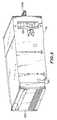
- FIG. 1 is a perspective view showing a multiple drivelibrary computer system;
- FIG. 2 is a diagrammatic view showing the six drivesof FIG. 1 connected to other library system components viaan I/O bus;
- FIG. 3 is a diagrammatic view showing a variation onthe system of FIG. 1 which includes twelve drives;
- FIG. 4 is an enhanced version of FIG. 1, wherein theI/O bus of FIG. 2 has been added to the figure, one of themodular drive housings has been removed to show thedetails of the drive/bus connections, and the library'sframe structure has been removed to reveal the system'srobotic media inserter;
- FIG. 5 is a rear perspective view of one of themodular drive housings shown in FIG. 1, wherein one full-heightdrive is mounted therein;
- FIG. 6 is a rear perspective view of the modular drivehousing of FIG. 5, wherein two half-height drives are nowmounted therein;
- FIG. 7 is a front perspective view of the modulardrive housing and drives of FIG. 6;
- FIG. 8 is a rear perspective view of the disassembledparts of FIG. 6, wherein I/O buses have been added;
- FIG. 9 is a flow chart of the steps involved in themethod of online drive repair disclosed herein;
- FIG. 10 is a table of the drive state definitions used in the method of online drive repair disclosed herein;
- FIG. 11 gives the specifications of the SCSI "WriteBuffer" command used by a host computer in accomplishingthe method of online drive repair disclosed herein; and
- FIG. 12 gives the specifications of the SCSI "ReadBuffer" command used by a host computer in accomplishingthe method of online drive repair disclosed herein.
- A multiple drive
library computer system 44 ispictured in FIGS. 1, 2 & 4, which may generally comprise anI/O bus 122, generally operating under a SCSI protocol,saidbus 122 comprising a primary I/O bus 94 and aplurality of secondary I/O buses primary bus 94, a plurality ofstorage drives librarycontroller 36, connected to said primary I/O bus 94, saidcontroller 36 comprising firmware to communicate with ahost computer 48 via said I/O bus 122, and firmware tocommunicate with said storage drives (50, 52...) via ageneral purpose bus 62. - Having thus described the multiple drive librarycomputer system in general, the system will now be described in further detail.
- In a first preferred embodiment, the
library system 44comprises six computer storage drives (50, 52...). Thestorage drives are housed in sixmodular housings - The drives (50, 52...) are connected to other librarysystem components via an internal I/
O bus 122. Thisbus 122 generally operates under a Small Computer SystemsInterface protocol (SCSI protocol). See FIG. 2. Theinternal I/O bus 122 further comprises a primary I/O bus 94, and a plurality of secondary I/O buses (96, 98...),pigtailed to said primary I/O bus 94. All storage drives(50, 52...) are connected to the I/O bus 122 via thesecondary (pigtailed) buses (96, 98...). - In FIG. 2, the primary I/
O bus 94 is shown runningbetweenconnectors O bus 94 may comprisetraces interposer boards Other sections O bus 94 may comprisestandard SCSI cabling. - A
general purpose bus 62 is connected between thestorage drives (50, 52...) and thelibrary controller 36. While the primary function of the SCSI protocol I/O bus 122is data transfer, the primary function of the generalpurpose bus is communication between the storage drives(50, 52...) and thelibrary controller 36. - FIG. 4 shows the rear face of a
storage drive 60. Thestorage drives (50, 52...) shown are optical, removablemedia type drives. See. FIG. 5. Each drive (50, 52...)has amedia inserting face 300 abutting arobotic mediainserter 40. Themedia inserting face 300 of adrive 60 isshown in FIG. 5. A typical placement of arobotic mediainserter 40 is best seen in FIG. 4. Robotic mediainserters for optical, removable media type drives aredisclosed in U.S. patent #5,010,536 and U.S. patent 5,730,031filed August 24, 1994.Opposite said media inserting faces 300, the drives (50,52...) have electrical connection faces 302. Eachelectrical connection face 302 has a connector (e.g.connector 304 ondrive 60 as shown in FIG. 4) forconnecting a secondary I/O bus (96, 98...) and a connectorto which a power cable may be attached (not shown). - The primary I/
O bus 94 is attached to a librarycontroller 36 (or autochanger controller) atconnector 76.As earlier mentioned, ageneral purpose bus 62 is also attached to the controller. Thecontroller 36 comprisesfirmware which allows it to communicate with the storagedrives (50, 52...) via thegeneral purpose bus 62. Thecontroller 36 also comprises firmware which allows it tocommunicate with a host 48 (whether it be a UNIX workstation, PC network server or otherwise) via the SCSIprotocol I/O bus 122. - The
controller 36 is responsive to host commands andmay perform such operations as keeping track of thelocation of removable media cartridges, moving removablemedia cartridges, and relaying its successes and/orfailures to thehost 48. Thecontroller 36 may alsoprocess and carry out library commands. Although thecontroller 36 may also be responsible for changing drivestates, in the preferred embodiment, this is left to thehost 48. Although thecontroller 36 contains amicroprocessor, the controller is a component which mayonly speak when spoken to - it cannot initiate action. - The
controller 36 may also comprise firmware whichallows it to enable or disable power to one or more storagedrives (50, 52...). In so enabling or disabling power, asystem for suppressing power transients is used. Thispower transient suppression system is similar to thatdisclosed in U.S. patent 5,587,687 filed October 31, 1994.Alternatively, switches (notshown) could be used to enable or disable power to thedrives (50, 52...). - An
LED interposer boards library system 44 or thehost 48to serve as a visual indication of the status of a drive(50, 52...) to a service technician. For example, alighted LED (64, 66...) could signify "power on", anunlighted LED (64, 66...) could signify "power off", and aflashing LED (64, 66...) could signify a powered drive inan "Offline_failed" state (this state will soon bedescribed in more detail). - A
SCSI repeater board 46 is also connected to theprimary I/O bus 94 viaconnector 90. See FIG. 2. Therepeater board 46 is contained withinrepeater boardenclosure 38. Therepeater board 46 is responsible forelectrically isolating I/O bus 122 from the outside world.It protects the protocol used onbus 122 from beingreconfigured by a component outside thelibrary system 44,such as thehost 48. Therepeater board 46 provides aninput 128 for anexternal SCSI bus 92 which connects thelibrary system 44 to ahost 48. Thehost 48 may be a UNIXwork station, PC network server, or other host device aspreviously mentioned. - The
repeater board 46 is especially important in thelibrary system 44 outlined above due to the configurationof the I/O bus 122. A typical SCSI system comprisesseveral components which are daisy-chained together. Thus,removing one component from the system causes a break inthe bus which can shut down communication with manycomponents. Since a purpose of this invention was toachieve an online repairable system, it became necessary toconstruct a cable which allowed for removal of a singlecomponent without disabling the entire bus. To achieve thedesired result, storage drives (50, 52...) are pigtailed toa primary I/O bus 94 via secondary I/O buses (96, 98...).Any secondary I/O bus (96, 98...) may be removed from thesystem without breaking the primary I/O bus 94 andinterfering with communication between other systemcomponents via the primary I/O bus 94. However, SCSIprotocol dictates that abus 122 may comprise no more thansix feet of cable, and a stub (such aspigtails primary bus 94 may be no longer than 100mm. Inthe preferred embodiment described above, theprimary bus 94 comprises approximately 1,5748 mm (62") of cable, and each pigtail (96, 98...) comprises approximately 30,48 cm (12") of cable. Thetotal cable length is 3,4036 m (11'2"). In order to successfully usea SCSI protocol on this newly invented bus cable, the I/Obus 122 must be isolated from the outside world, and cannotbe subject to reconfiguration. Therepeater board 46serves this important function. - The storage drives (50, 52...) are mounted to thelibrary
system frame structure 42 via modular drivehousings (20, 22...). - FIG. 5 shows a
modular drive housing 30 removed fromthelibrary system 44. Each modular drive housing (20,22...) comprises itsown cooling fan handle library system 44. See also, FIG. 4. - Removal of a modular drive housing (20, 22...) isaccomplished by first disconnecting any cabling extendingfrom said modular housing (20, 22...) (such as I/O buscables (96, 98...) and any power cables (not shown)).Since the electrical connection faces 302 of the drives (50, 52...) are not readily accessible while the drives(50, 52...) are mounted within a modular housing (20,22...), cabling is disconnected at the
interposer boards 32& 34. As a consequence, secondary I/O buses (96, 98...)and portions of power cables will be removed with a modularhousing (20, 22...). Once cabling is disconnected, amodular housing 30 may be removed from thelibrary system 44. Cabling is not shown in FIG. 5 so as not to interferewith a view of coolingfan 320 and handle 340. A modularhousing (20, 22...) is removed by pulling the modularhousing (20, 22...) away from therobotic media inserter 40. Handles (330, 332...) on the modular housings (20,22...) facilitate their removal. By way of example, amodular housing 30, and thedrive 60 mounted therein, areremoved from thelibrary system 44 as a unit in FIG. 5. - In a second preferred embodiment, the
library system 44 comprises twelve computer storage drives 150, 151, 152,153, 154, 155, 156, 157, 158, 159, 160, 161. The twelvestorage drives (150, 151...) are housed in the same sixmodular housings (20, 22...) identified above. Eachmodular housing (20, 22...) is designed so that it may,without any modification, hold either one full-height drive(50, 52...) or two half-height drives (150, 151...). - The drives (150, 151...) are connected to other system components via two internal I/
O buses bus O buses primary bus 194 which includesseveral cable sections numerous connectors secondarybuses O bus 122 comprisesaprimary bus 195 which again includesseveral cablesections numerous connectors secondary buses drives secondary buses drives O buses drives O buses - As in the first embodiment, a
general purposes bus 162runs between the storage drives (150, 151...) and thelibrary controller 36.Upper 132 and lower 134 PCinterposer boards again provide mounts forbus connectors - Due to the presence of two SCSI I/
O buses host 48 is connected to each oftherepeater boards - FIG. 6 shows a rear view of the
modular housing 30 ofFIG. 5, wherein two half-height drives 160, 161 have beensubstituted for the one full-height drive 60. Themediainserting faces 340 of the two half-height drives 160, 161are seen extending from the rear of thehousing 30. FIG. 7shows a front perspective view of the components of FIG. 6.FIG. 8 shows the two half-height drives 160, 161 andmodular housing 30 of FIG. 6 in a disassembled fashion.The secondary I/O bus 206 and daisy-chained I/O bus 207which connect the storage drives shown 160, 161 to theprimary I/O bus 195 are also shown in FIG. 8. Aspreviously stated, these I/O buses modular housing 30as a unit. In this embodiment, the secondary I/O buses(196, 198...) are approximately 35,56 cm (fourteen inches) in length.Finally, FIG. 8 reveals the threesubsections modular housing 30. - Our method of repairing one or more drives in themultiple drive library computer systems described above isas follows. For purposes of this description, it will be assumed that the failed drive is a half-
height drive 160housed as a pair with another half-height drive 161 in asingularmodular housing 30 contained within a systemsimilar to that described in the second preferredembodiment described above. However, it is important tokeep in mind that this method is also applicable to therepair of a full-height drive, or a drive in a librarysystem wherein more than two drives are mounted within asingularmodular housing 30. The method is also applicableto the repair of two or more drives at the same time. - First, the failure of a drive must be detected orinstructed. Refer to the flow chart in FIG. 9. This maybe done by either the
library controller 36 and/or thehost 48. In the preferred method, the host's software providesthe means for detecting when adrive 160 has failed. Thehost 48 may detect that adrive 160 has failed by severalavenues. If thehost 48 issues a command to the library toeject or load media to adrive 160 and receives a statuscode back from thelibrary controller 36 indicating thatthe move operation was unsuccessful, thehost 48 may assumethat thedrive 160 was at fault and is in need or repair.Thehost 48 may also detect drive failure from a systemlevel error indicating that thedrive 160 is notfunctioning correctly. - Once a drive's failure is detected, the
host 48attempts to remove media from the failed drive, if any ispresent. After removing media, thehost 48 informs thelibrary controller 36 of the drive failure, and places thedrive 160 in an "Offline_failed" state. (Note: adescription of all of the various drive states is found inFIG. 10) Thelibrary controller 36 will store the drivestate information, and will not allow further access to thefaileddrive 160 until its state is changed to"Online_good". Drive states remain through power cycling. - The failed
drive 160 may be serviced while thelibrarysystem 44 remains online. It is therefore possible for thehost 48 to continue accessing one or moregood drives drive 160 isbeing repaired. - While the
library system 44 remains operational, aqualified service person accesses the internal workings ofthe library (shown in FIG. 1). The service person willknow which drive is in an "Offline_failed" state by aflashingLED 174 near thedrive 160. If, as assumed, afailed drive is mounted in amodular housing 30 containingtwo half-height drives 160, 161, bothdrives drive 160 will actually be replaced. - In the preferred embodiment, the
host 48 will placethegood drive 161 which is commonly housed with the faileddrive 160 in an "Offline_good_pending" state. Thehost 48can then remove media from the commonly housedgood drive 161 before placing it in an "Offline_good" state. - With both
drives library controller 36 will remove power to the drive pair.LEDs drive pair drives O bus cable 206 may be safelydisconnected from the primary I/O bus 195. Power cables tothe drives (not shown) may also be disconnected at thePCinterposer board 134 corresponding to thedrives system 44 or thehost 48 will occur. - The
modular housing 30 containing the faileddrive 160may now be removed. Themodular housing 30 is removed bypulling it away from therobotic media inserter 40. Byremoving thedrives robotic media inserter 40 is not interrupted as itcontinues to feed media to the library'sgood drives - After the failed
drive 160 is replaced, the removedmodular housing 30 is again mounted in its place, andcabling is reconnected to the removed drives 160, 161, theservice technician sets the drive pair status to"Online_pending" via a switch (not shown) on thecorrespondingPC interposer board 134 which alerts thelibrary controller 36. Thelibrary controller 36 will thenapply power to thedrive pair host 48 of the drive state changes. Thehost 48then changes the states of the "Online_pending" drives to"Online_good". All of the library's drives (150, 151...)are now accessible to thehost 48. - The
host 48 may only access a drive (150, 151...) whenit is in an "Online_good" or "Offline_good_pending" state.At all other times, thelibrary controller 36 will denyaccess to a drive (150, 151...). - The
host 48 changes drive states for the drives (150,151...) via a SCSI "Write Buffer" command. Whenever thehost 48 wants to change the state of a drive, it willsimply issue the appropriate "Write Buffer" command. SeeFIG. 11 for specifications of the SCSI "Write Buffer"command. - The
library controller 36 communicates to thehost 48via the SCSI "Unit Attention" condition. Whenever thelibrary controller 36 wants to inform thehost 48 of achange in the state(s) of the drive(s), it issues a "UnitAttention" condition on the next SCSI command sent by thehost 48. Upon receiving the "Unit Attention" condition,thehost 48 will send a SCSI "Read Buffer" command todetermine the state change(s) of the drive(s). See FIG. 12for specifications of the SCSI "Read Buffer" command.Specifications for the "Unit Attention" condition are asfollows:"Request Sense" data for the SCSI "Unit Attention" Condition: Sense Key = 6 (Unit Attention) ASC = 0x2A (Parameters Changed) ASCQ = 0x80 (Vendor Unique for HP Libraries) - The
library controller 36 will respond with a "UnitAttention" condition to any command from the host 48(except Inquiry) when there is a pending state change forone or more of the library's storage drives (150, 151...).Thehost 48 must then send a "Read Buffer" command todetermine the state change. The "Unit Attention" conditionwill only be reported once per state change. Thehost 48may poll thelibrary controller 36 with the "Read Buffer"command, if desired. - The
library controller 36 will respond with an "Illegal Request" condition to any Move or Exchange commandfrom thehost 48 that involves a drive that is not in an"Online_good" or "Offline_good_pending" state. Thespecifications for the SCSI "Illegal Request" Condition aregiven below:"Request Sense" data for the SCSI "Illegal Request" condition: Sense Key = 5 (Illegal Request) ASC = 0x22 (Illegal Function) ASCQ = 0x80 (Vendor Unique for HP Libraries)
Claims (9)
- A multiple drive library computer system (44),comprising:
a primary structure (42) to which is mounted a number ofelectronic and mechanical subsystems (32, 34, 36, 46),said subsystems including a robotic media inserter (40);
characterized bytwo or more modular drive housings (20, 22, 24, 26, 28,30), detachably mounted to said primary structure, ineach of which are mounted one or more SCSI storage-drives(50, 52, 54, 56, 58, 60), each SCSI storage drivehaving an electrical connection face (302) opposite amedia-inserting face (300) and being connectable to oneor more of the number of subsystems via cables, whereineach of said modular drive housings holds themedia-inserting faces of its SCSI storage drives inabutment to, and in cooperating engagement with therobotic media inserter;wherein each of the two or more modular drive housings are adapted to be removed from said primarystructure by pulling the modular drive housing away from therobotic media inserter (40). - A system (44) as in claim 1, wherein each modulardrive housing (20, 22, 24, 26, 28, 30) has a cooling fan(310, 312, 314, 316, 318, 320) mounted thereon.
- A system (44) as in claim 1 or 2, wherein eachmodular drive housing (20, 22, 24, 26, 28, 30) is of asize and shape to house one or two of said SCSI storage drives (50, 52, 54, 56, 58, 60).
- A system (44) as in one of claims 1 to 3, whereineach of the one or more SCSI storage drives (50, 52, 54,56, 58, 60) is an optical media drive, and the roboticmedia inserter (40) is an optical media inserter.
- A system (44) as in claim 4, wherein each of the oneor more SCSI storage drives (50, 52, 54, 56, 58, 60) isa CD-ROM drive.
- A system (44) as in one of claims 1 to 5, whereineach modular drive housing (20, 22, 24, 26, 28, 30)further comprises a handle (330, 332, 334, 336, 338,340).
- A system (44) as in one of claims 1 to 6, whereineach modular drive housing (20, 22, 24, 26, 28, 30)further comprises an orifice for routing the cables (96,98, 100, 102, 104, 106) between the one or more of thenumber of electrical subsystems (32, 34, 36, 46) and theSCSI storage drives (50, 52, 54, 56, 58, 60) mountedwithin a modular drive housing, said orifice beinglocated in close proximity to said electrical connectionfaces (302) of the SCSI storage drives mounted within amodular drive housing.
- A system (44) as in one of claims 2 to 7, wherein thecooling fans (310, 312, 314, 316, 318, 320) mounted onthe modular drive housings (20, 22, 24, 26, 28, 30) aremounted on walls of the modular drive housings which areparallel to, and most proximate to, the electricalconnection faces (302) of SCSI storage drives (50, 52,54, 56, 58, 60) mounted within the modular drivehousings.
- A system as in claim 8, wherein the cooling fans(310, 312, 314, 316, 318, 320) are centrally mounted on walls of the modular drive housings which are parallelto, and most proximate to, the electrical connectionfaces (302) of SCSI storage drives (50, 52, 54, 56, 58,60) mounted within the modular drive housings.
Applications Claiming Priority (2)
| Application Number | Priority Date | Filing Date | Title |
|---|---|---|---|
| US50906595A | 1995-07-31 | 1995-07-31 | |
| US509065 | 1995-07-31 |
Publications (3)
| Publication Number | Publication Date |
|---|---|
| EP0757351A2 EP0757351A2 (en) | 1997-02-05 |
| EP0757351A3 EP0757351A3 (en) | 1997-03-26 |
| EP0757351B1true EP0757351B1 (en) | 2001-08-16 |
Family
ID=24025131
Family Applications (1)
| Application Number | Title | Priority Date | Filing Date |
|---|---|---|---|
| EP96109263AExpired - LifetimeEP0757351B1 (en) | 1995-07-31 | 1996-06-10 | Computer frame structure with modular housings |
Country Status (4)
| Country | Link |
|---|---|
| US (1) | US5761032A (en) |
| EP (1) | EP0757351B1 (en) |
| JP (2) | JP4528372B2 (en) |
| DE (1) | DE69614460T2 (en) |
Cited By (23)
| Publication number | Priority date | Publication date | Assignee | Title |
|---|---|---|---|---|
| US7778031B1 (en) | 2009-07-15 | 2010-08-17 | Teradyne, Inc. | Test slot cooling system for a storage device testing system |
| US7848106B2 (en) | 2008-04-17 | 2010-12-07 | Teradyne, Inc. | Temperature control within disk drive testing systems |
| US7890207B2 (en) | 2008-04-17 | 2011-02-15 | Teradyne, Inc. | Transferring storage devices within storage device testing systems |
| US7904211B2 (en) | 2008-04-17 | 2011-03-08 | Teradyne, Inc. | Dependent temperature control within disk drive testing systems |
| US7908029B2 (en) | 2008-06-03 | 2011-03-15 | Teradyne, Inc. | Processing storage devices |
| US7911778B2 (en) | 2008-04-17 | 2011-03-22 | Teradyne, Inc. | Vibration isolation within disk drive testing systems |
| US7929303B1 (en) | 2010-02-02 | 2011-04-19 | Teradyne, Inc. | Storage device testing system cooling |
| US7932734B2 (en) | 2009-07-15 | 2011-04-26 | Teradyne, Inc. | Individually heating storage devices in a testing system |
| US7940529B2 (en) | 2009-07-15 | 2011-05-10 | Teradyne, Inc. | Storage device temperature sensing |
| US7945424B2 (en) | 2008-04-17 | 2011-05-17 | Teradyne, Inc. | Disk drive emulator and method of use thereof |
| US7987018B2 (en) | 2008-04-17 | 2011-07-26 | Teradyne, Inc. | Transferring disk drives within disk drive testing systems |
| US7996174B2 (en) | 2007-12-18 | 2011-08-09 | Teradyne, Inc. | Disk drive testing |
| US8041449B2 (en) | 2008-04-17 | 2011-10-18 | Teradyne, Inc. | Bulk feeding disk drives to disk drive testing systems |
| US8102173B2 (en) | 2008-04-17 | 2012-01-24 | Teradyne, Inc. | Thermal control system for test slot of test rack for disk drive testing system with thermoelectric device and a cooling conduit |
| US8116079B2 (en) | 2009-07-15 | 2012-02-14 | Teradyne, Inc. | Storage device testing system cooling |
| US8238099B2 (en) | 2008-04-17 | 2012-08-07 | Teradyne, Inc. | Enclosed operating area for disk drive testing systems |
| US8405971B2 (en) | 2007-12-18 | 2013-03-26 | Teradyne, Inc. | Disk drive transport, clamping and testing |
| US8482915B2 (en) | 2008-04-17 | 2013-07-09 | Teradyne, Inc. | Temperature control within disk drive testing systems |
| US8547123B2 (en) | 2009-07-15 | 2013-10-01 | Teradyne, Inc. | Storage device testing system with a conductive heating assembly |
| US8628239B2 (en) | 2009-07-15 | 2014-01-14 | Teradyne, Inc. | Storage device temperature sensing |
| US8687349B2 (en) | 2010-07-21 | 2014-04-01 | Teradyne, Inc. | Bulk transfer of storage devices using manual loading |
| US9001456B2 (en) | 2010-08-31 | 2015-04-07 | Teradyne, Inc. | Engaging test slots |
| US9459312B2 (en) | 2013-04-10 | 2016-10-04 | Teradyne, Inc. | Electronic assembly test system |
Families Citing this family (38)
| Publication number | Priority date | Publication date | Assignee | Title |
|---|---|---|---|---|
| US6272573B1 (en) | 1997-12-24 | 2001-08-07 | International Business Machines Corporation | Scalable modular data storage system |
| US6148352A (en)* | 1997-12-24 | 2000-11-14 | International Business Machines Corporation | Scalable modular data storage system |
| TW398651U (en)* | 1997-12-31 | 2000-07-11 | Global Win Technology Co Ltd | Cooling structure of hard disc |
| US6460098B1 (en)* | 1999-06-14 | 2002-10-01 | Storcase Technology | Low voltage differential SCSI bus interconnect system having repeater means |
| TW453620U (en)* | 1999-07-09 | 2001-09-01 | Asustek Comp Inc | External-connected auxiliary device of portable computer |
| US6473371B1 (en)* | 2000-02-14 | 2002-10-29 | Hewlett-Packard Company | Media handling device having replaceable modules |
| US6693859B1 (en) | 2001-04-26 | 2004-02-17 | International Business Machines Corporation | Gripper assembly apparatus for interfacing with a storage device |
| US6826004B2 (en) | 2001-04-26 | 2004-11-30 | International Business Machines Corporation | Gripper assembly for interfacing with portable storage devices in a storage library |
| US6731455B2 (en) | 2001-04-26 | 2004-05-04 | International Business Machines Corporation | Automated library system including a gripper assembly apparatus for interfacing with a storage device |
| US6874100B2 (en)* | 2001-07-12 | 2005-03-29 | Digi-Data Corporation | Raid system with multiple controllers and proof against any single point of failure |
| US6733223B2 (en)* | 2001-08-23 | 2004-05-11 | Hewlett-Packard Development Company, L.P. | Systems and methods for providing a removable media handling system in data storage system |
| DE60215680T2 (en)* | 2001-08-29 | 2007-08-23 | Xyratex Technology Ltd., Havant | HOLDING DEVICE FOR DISK UNIT AND METHOD OF HANDLING |
| US7019940B2 (en)* | 2001-09-24 | 2006-03-28 | Hewlett-Packard Development Company, L.P. | Universal cartridge magazine system and method |
| US6965811B2 (en)* | 2003-07-14 | 2005-11-15 | Quantum Corporation | Media drive module and storage library system |
| US7079392B2 (en)* | 2003-11-26 | 2006-07-18 | International Business Machines Corporation | Slim-line mounting mechanism for electronic packaging |
| JP4335760B2 (en)* | 2004-07-08 | 2009-09-30 | 富士通株式会社 | Rack mount storage unit and rack mount disk array device |
| US7542298B1 (en) | 2005-03-30 | 2009-06-02 | Storage Technology Corporation | Automated modular library and associated methods |
| US7512718B2 (en)* | 2005-04-20 | 2009-03-31 | Lawrence J. Dickson | Reconfigurable computing array without chassis |
| US7688578B2 (en)* | 2007-07-19 | 2010-03-30 | Hewlett-Packard Development Company, L.P. | Modular high-density computer system |
| US9245575B2 (en)* | 2007-09-28 | 2016-01-26 | Nec Platforms, Ltd. | Library device |
| GB0823407D0 (en)* | 2008-12-23 | 2009-01-28 | Nexan Technologies Ltd | Apparatus for storing data |
| GB2467404B (en)* | 2008-12-23 | 2011-12-14 | Nexsan Technologies Ltd | Electronic apparatus |
| JP4685173B2 (en) | 2009-02-04 | 2011-05-18 | 富士通株式会社 | Storage device, storage device maintenance method, and storage device maintenance program |
| US9779780B2 (en) | 2010-06-17 | 2017-10-03 | Teradyne, Inc. | Damping vibrations within storage device testing systems |
| WO2014018753A1 (en)* | 2012-07-25 | 2014-01-30 | Niksun, Inc. | Configurable network monitoring system |
| US10845410B2 (en) | 2017-08-28 | 2020-11-24 | Teradyne, Inc. | Automated test system having orthogonal robots |
| US10725091B2 (en) | 2017-08-28 | 2020-07-28 | Teradyne, Inc. | Automated test system having multiple stages |
| US10948534B2 (en) | 2017-08-28 | 2021-03-16 | Teradyne, Inc. | Automated test system employing robotics |
| US11226390B2 (en) | 2017-08-28 | 2022-01-18 | Teradyne, Inc. | Calibration process for an automated test system |
| US10983145B2 (en) | 2018-04-24 | 2021-04-20 | Teradyne, Inc. | System for testing devices inside of carriers |
| US10775408B2 (en) | 2018-08-20 | 2020-09-15 | Teradyne, Inc. | System for testing devices inside of carriers |
| US11605401B2 (en)* | 2020-04-29 | 2023-03-14 | Quantum Corporation | Automatic implementation of a physical barrier to protect removable storage media access |
| US11953519B2 (en) | 2020-10-22 | 2024-04-09 | Teradyne, Inc. | Modular automated test system |
| US11754596B2 (en) | 2020-10-22 | 2023-09-12 | Teradyne, Inc. | Test site configuration in an automated test system |
| US11867749B2 (en) | 2020-10-22 | 2024-01-09 | Teradyne, Inc. | Vision system for an automated test system |
| US11899042B2 (en) | 2020-10-22 | 2024-02-13 | Teradyne, Inc. | Automated test system |
| US11754622B2 (en) | 2020-10-22 | 2023-09-12 | Teradyne, Inc. | Thermal control system for an automated test system |
| US12007411B2 (en) | 2021-06-22 | 2024-06-11 | Teradyne, Inc. | Test socket having an automated lid |
Citations (1)
| Publication number | Priority date | Publication date | Assignee | Title |
|---|---|---|---|---|
| EP0289986A2 (en)* | 1987-05-08 | 1988-11-09 | Indelt Costruzioni Elettroniche Srl | System and apparatus for the automatic handling of pre-recorded radio or television programmes, or like activities and its particular store |
Family Cites Families (8)
| Publication number | Priority date | Publication date | Assignee | Title |
|---|---|---|---|---|
| US4754397A (en)* | 1985-02-15 | 1988-06-28 | Tandem Computers Incorporated | Fault tolerant modular subsystems for computers |
| US4853830A (en)* | 1988-03-17 | 1989-08-01 | International Business Machines Corporation | Three stage self alignment structure and method |
| US5041924A (en)* | 1988-11-30 | 1991-08-20 | Quantum Corporation | Removable and transportable hard disk subsystem |
| US5010536A (en)* | 1989-02-22 | 1991-04-23 | Hewlett-Packard Company | Cartridge handling system |
| US5208813A (en)* | 1990-10-23 | 1993-05-04 | Array Technology Corporation | On-line reconstruction of a failed redundant array system |
| US5224019A (en)* | 1991-03-15 | 1993-06-29 | Amkly Systems, Inc. | Modular computer assembly |
| US5371743A (en)* | 1992-03-06 | 1994-12-06 | Data General Corporation | On-line module replacement in a multiple module data processing system |
| US5277615A (en)* | 1992-09-24 | 1994-01-11 | Compaq Computer Corporation | Apparatus for removably supporting a plurality of hot plug-connected hard disk drives |
- 1996
- 1996-06-10EPEP96109263Apatent/EP0757351B1/ennot_activeExpired - Lifetime
- 1996-06-10DEDE69614460Tpatent/DE69614460T2/ennot_activeExpired - Lifetime
- 1996-07-24JPJP19452096Apatent/JP4528372B2/ennot_activeExpired - Lifetime
- 1997
- 1997-03-17USUS08/819,154patent/US5761032A/ennot_activeExpired - Lifetime
- 2007
- 2007-05-08JPJP2007123164Apatent/JP2007305290A/enactivePending
Patent Citations (1)
| Publication number | Priority date | Publication date | Assignee | Title |
|---|---|---|---|---|
| EP0289986A2 (en)* | 1987-05-08 | 1988-11-09 | Indelt Costruzioni Elettroniche Srl | System and apparatus for the automatic handling of pre-recorded radio or television programmes, or like activities and its particular store |
Cited By (40)
| Publication number | Priority date | Publication date | Assignee | Title |
|---|---|---|---|---|
| US7996174B2 (en) | 2007-12-18 | 2011-08-09 | Teradyne, Inc. | Disk drive testing |
| US8549912B2 (en) | 2007-12-18 | 2013-10-08 | Teradyne, Inc. | Disk drive transport, clamping and testing |
| US8467180B2 (en) | 2007-12-18 | 2013-06-18 | Teradyne, Inc. | Disk drive transport, clamping and testing |
| US8405971B2 (en) | 2007-12-18 | 2013-03-26 | Teradyne, Inc. | Disk drive transport, clamping and testing |
| US8140182B2 (en) | 2008-04-17 | 2012-03-20 | Teradyne, Inc. | Bulk feeding disk drives to disk drive testing systems |
| US8482915B2 (en) | 2008-04-17 | 2013-07-09 | Teradyne, Inc. | Temperature control within disk drive testing systems |
| US8712580B2 (en) | 2008-04-17 | 2014-04-29 | Teradyne, Inc. | Transferring storage devices within storage device testing systems |
| US8655482B2 (en) | 2008-04-17 | 2014-02-18 | Teradyne, Inc. | Enclosed operating area for storage device testing systems |
| US8238099B2 (en) | 2008-04-17 | 2012-08-07 | Teradyne, Inc. | Enclosed operating area for disk drive testing systems |
| US7848106B2 (en) | 2008-04-17 | 2010-12-07 | Teradyne, Inc. | Temperature control within disk drive testing systems |
| US7945424B2 (en) | 2008-04-17 | 2011-05-17 | Teradyne, Inc. | Disk drive emulator and method of use thereof |
| US7987018B2 (en) | 2008-04-17 | 2011-07-26 | Teradyne, Inc. | Transferring disk drives within disk drive testing systems |
| US7890207B2 (en) | 2008-04-17 | 2011-02-15 | Teradyne, Inc. | Transferring storage devices within storage device testing systems |
| US8451608B2 (en) | 2008-04-17 | 2013-05-28 | Teradyne, Inc. | Temperature control within storage device testing systems |
| US8041449B2 (en) | 2008-04-17 | 2011-10-18 | Teradyne, Inc. | Bulk feeding disk drives to disk drive testing systems |
| US7904211B2 (en) | 2008-04-17 | 2011-03-08 | Teradyne, Inc. | Dependent temperature control within disk drive testing systems |
| US8095234B2 (en) | 2008-04-17 | 2012-01-10 | Teradyne, Inc. | Transferring disk drives within disk drive testing systems |
| US8102173B2 (en) | 2008-04-17 | 2012-01-24 | Teradyne, Inc. | Thermal control system for test slot of test rack for disk drive testing system with thermoelectric device and a cooling conduit |
| US8117480B2 (en) | 2008-04-17 | 2012-02-14 | Teradyne, Inc. | Dependent temperature control within disk drive testing systems |
| US8305751B2 (en) | 2008-04-17 | 2012-11-06 | Teradyne, Inc. | Vibration isolation within disk drive testing systems |
| US8160739B2 (en) | 2008-04-17 | 2012-04-17 | Teradyne, Inc. | Transferring storage devices within storage device testing systems |
| US7911778B2 (en) | 2008-04-17 | 2011-03-22 | Teradyne, Inc. | Vibration isolation within disk drive testing systems |
| US8086343B2 (en) | 2008-06-03 | 2011-12-27 | Teradyne, Inc. | Processing storage devices |
| US7908029B2 (en) | 2008-06-03 | 2011-03-15 | Teradyne, Inc. | Processing storage devices |
| US7940529B2 (en) | 2009-07-15 | 2011-05-10 | Teradyne, Inc. | Storage device temperature sensing |
| US8116079B2 (en) | 2009-07-15 | 2012-02-14 | Teradyne, Inc. | Storage device testing system cooling |
| US8279603B2 (en) | 2009-07-15 | 2012-10-02 | Teradyne, Inc. | Test slot cooling system for a storage device testing system |
| US7995349B2 (en) | 2009-07-15 | 2011-08-09 | Teradyne, Inc. | Storage device temperature sensing |
| US8466699B2 (en) | 2009-07-15 | 2013-06-18 | Teradyne, Inc. | Heating storage devices in a testing system |
| US8628239B2 (en) | 2009-07-15 | 2014-01-14 | Teradyne, Inc. | Storage device temperature sensing |
| US7778031B1 (en) | 2009-07-15 | 2010-08-17 | Teradyne, Inc. | Test slot cooling system for a storage device testing system |
| US8547123B2 (en) | 2009-07-15 | 2013-10-01 | Teradyne, Inc. | Storage device testing system with a conductive heating assembly |
| US7932734B2 (en) | 2009-07-15 | 2011-04-26 | Teradyne, Inc. | Individually heating storage devices in a testing system |
| US7920380B2 (en) | 2009-07-15 | 2011-04-05 | Teradyne, Inc. | Test slot cooling system for a storage device testing system |
| US8687356B2 (en) | 2010-02-02 | 2014-04-01 | Teradyne, Inc. | Storage device testing system cooling |
| US7929303B1 (en) | 2010-02-02 | 2011-04-19 | Teradyne, Inc. | Storage device testing system cooling |
| US8687349B2 (en) | 2010-07-21 | 2014-04-01 | Teradyne, Inc. | Bulk transfer of storage devices using manual loading |
| US8964361B2 (en) | 2010-07-21 | 2015-02-24 | Teradyne, Inc. | Bulk transfer of storage devices using manual loading |
| US9001456B2 (en) | 2010-08-31 | 2015-04-07 | Teradyne, Inc. | Engaging test slots |
| US9459312B2 (en) | 2013-04-10 | 2016-10-04 | Teradyne, Inc. | Electronic assembly test system |
Also Published As
| Publication number | Publication date |
|---|---|
| DE69614460T2 (en) | 2002-06-06 |
| EP0757351A3 (en) | 1997-03-26 |
| EP0757351A2 (en) | 1997-02-05 |
| JP2007305290A (en) | 2007-11-22 |
| JP4528372B2 (en) | 2010-08-18 |
| US5761032A (en) | 1998-06-02 |
| DE69614460D1 (en) | 2001-09-20 |
| JPH0982081A (en) | 1997-03-28 |
Similar Documents
| Publication | Publication Date | Title |
|---|---|---|
| EP0757351B1 (en) | Computer frame structure with modular housings | |
| EP0757320B1 (en) | Online drive repair in a multiple drive library computer system | |
| EP0242970B1 (en) | Fault tolerant modular computing system | |
| US8009385B2 (en) | High density array system with active movable media drawers | |
| US6483107B1 (en) | Canister having a combined guide rail and light pipe system for use in a computer peripheral enclosure | |
| US6148352A (en) | Scalable modular data storage system | |
| US20070233781A1 (en) | High density array system having multiple storage units with active movable media drawers | |
| WO2007115206A2 (en) | High density array system with active storage media support structures | |
| US20070230109A1 (en) | High density array system with active storage blades | |
| US6970974B2 (en) | Method for managing disk drives of different types in disk array device | |
| US6378084B1 (en) | Enclosure processor with failover capability | |
| EP0757321B1 (en) | I/O bus in a multiple drive library computer system | |
| US6061250A (en) | Full enclosure chassis system with tool-free access to hot-pluggable circuit boards therein | |
| US20150177781A1 (en) | Data storage device enclosure and module | |
| US7233548B2 (en) | Power supply apparatus and method using same | |
| JPH1040637A (en) | Information management device | |
| US20050250533A1 (en) | Wireless storage enterprise connectivity | |
| Cisco | Control Circuit Cards | |
| US20090179535A1 (en) | Storage component of a server arrangement with a plurality of hard disk drives | |
| EP0898219A1 (en) | Upgrading a storage media bay | |
| JPH06215553A (en) | Detachable disk-drive-carrier assembly | |
| JPH10333794A (en) | I / O device hot-swap method, I / O device mounting structure for realizing the method, and I / O subsystem |
Legal Events
| Date | Code | Title | Description |
|---|---|---|---|
| PUAI | Public reference made under article 153(3) epc to a published international application that has entered the european phase | Free format text:ORIGINAL CODE: 0009012 | |
| AK | Designated contracting states | Kind code of ref document:A2 Designated state(s):DE GB NL | |
| PUAL | Search report despatched | Free format text:ORIGINAL CODE: 0009013 | |
| AK | Designated contracting states | Kind code of ref document:A3 Designated state(s):DE GB NL | |
| 17P | Request for examination filed | Effective date:19970515 | |
| 17Q | First examination report despatched | Effective date:19990608 | |
| GRAG | Despatch of communication of intention to grant | Free format text:ORIGINAL CODE: EPIDOS AGRA | |
| GRAG | Despatch of communication of intention to grant | Free format text:ORIGINAL CODE: EPIDOS AGRA | |
| GRAH | Despatch of communication of intention to grant a patent | Free format text:ORIGINAL CODE: EPIDOS IGRA | |
| GRAH | Despatch of communication of intention to grant a patent | Free format text:ORIGINAL CODE: EPIDOS IGRA | |
| RAP1 | Party data changed (applicant data changed or rights of an application transferred) | Owner name:HEWLETT-PACKARD COMPANY, A DELAWARE CORPORATION | |
| GRAA | (expected) grant | Free format text:ORIGINAL CODE: 0009210 | |
| AK | Designated contracting states | Kind code of ref document:B1 Designated state(s):DE GB NL | |
| REF | Corresponds to: | Ref document number:69614460 Country of ref document:DE Date of ref document:20010920 | |
| REG | Reference to a national code | Ref country code:GB Ref legal event code:IF02 | |
| PLBE | No opposition filed within time limit | Free format text:ORIGINAL CODE: 0009261 | |
| STAA | Information on the status of an ep patent application or granted ep patent | Free format text:STATUS: NO OPPOSITION FILED WITHIN TIME LIMIT | |
| 26N | No opposition filed | ||
| REG | Reference to a national code | Ref country code:GB Ref legal event code:732E Free format text:REGISTERED BETWEEN 20120329 AND 20120404 | |
| REG | Reference to a national code | Ref country code:NL Ref legal event code:SD Effective date:20120731 | |
| PGFP | Annual fee paid to national office [announced via postgrant information from national office to epo] | Ref country code:DE Payment date:20150521 Year of fee payment:20 Ref country code:GB Payment date:20150527 Year of fee payment:20 | |
| PGFP | Annual fee paid to national office [announced via postgrant information from national office to epo] | Ref country code:NL Payment date:20150521 Year of fee payment:20 | |
| REG | Reference to a national code | Ref country code:DE Ref legal event code:R082 Ref document number:69614460 Country of ref document:DE Representative=s name:SCHOPPE, ZIMMERMANN, STOECKELER, ZINKLER, SCHE, DE Ref country code:DE Ref legal event code:R081 Ref document number:69614460 Country of ref document:DE Owner name:HEWLETT PACKARD ENTERPRISE DEVELOPMENT LP, HOU, US Free format text:FORMER OWNER: HEWLETT-PACKARD DEVELOPMENT COMPANY, L.P., HOUSTON, TEX., US | |
| REG | Reference to a national code | Ref country code:DE Ref legal event code:R071 Ref document number:69614460 Country of ref document:DE Ref country code:NL Ref legal event code:MK Effective date:20160609 | |
| REG | Reference to a national code | Ref country code:GB Ref legal event code:PE20 Expiry date:20160609 | |
| PG25 | Lapsed in a contracting state [announced via postgrant information from national office to epo] | Ref country code:GB Free format text:LAPSE BECAUSE OF EXPIRATION OF PROTECTION Effective date:20160609 | |
| REG | Reference to a national code | Ref country code:GB Ref legal event code:732E Free format text:REGISTERED BETWEEN 20160825 AND 20160831 |