EP0752680B1 - Optical scanners having dual surface optical elements for dual working ranges - Google Patents
Optical scanners having dual surface optical elements for dual working rangesDownload PDFInfo
- Publication number
- EP0752680B1 EP0752680B1EP96104236AEP96104236AEP0752680B1EP 0752680 B1EP0752680 B1EP 0752680B1EP 96104236 AEP96104236 AEP 96104236AEP 96104236 AEP96104236 AEP 96104236AEP 0752680 B1EP0752680 B1EP 0752680B1
- Authority
- EP
- European Patent Office
- Prior art keywords
- scanner
- light
- mirror
- indicia
- optical element
- Prior art date
- Legal status (The legal status is an assumption and is not a legal conclusion. Google has not performed a legal analysis and makes no representation as to the accuracy of the status listed.)
- Expired - Lifetime
Links
Images


Classifications
- G—PHYSICS
- G06—COMPUTING OR CALCULATING; COUNTING
- G06K—GRAPHICAL DATA READING; PRESENTATION OF DATA; RECORD CARRIERS; HANDLING RECORD CARRIERS
- G06K7/00—Methods or arrangements for sensing record carriers, e.g. for reading patterns
- G06K7/10—Methods or arrangements for sensing record carriers, e.g. for reading patterns by electromagnetic radiation, e.g. optical sensing; by corpuscular radiation
- G06K7/10544—Methods or arrangements for sensing record carriers, e.g. for reading patterns by electromagnetic radiation, e.g. optical sensing; by corpuscular radiation by scanning of the records by radiation in the optical part of the electromagnetic spectrum
- G06K7/10792—Special measures in relation to the object to be scanned
- G06K7/10801—Multidistance reading
- G—PHYSICS
- G06—COMPUTING OR CALCULATING; COUNTING
- G06K—GRAPHICAL DATA READING; PRESENTATION OF DATA; RECORD CARRIERS; HANDLING RECORD CARRIERS
- G06K7/00—Methods or arrangements for sensing record carriers, e.g. for reading patterns
- G06K7/10—Methods or arrangements for sensing record carriers, e.g. for reading patterns by electromagnetic radiation, e.g. optical sensing; by corpuscular radiation
- G06K7/10544—Methods or arrangements for sensing record carriers, e.g. for reading patterns by electromagnetic radiation, e.g. optical sensing; by corpuscular radiation by scanning of the records by radiation in the optical part of the electromagnetic spectrum
- G06K7/10554—Moving beam scanning
- G06K7/10594—Beam path
- G06K7/10603—Basic scanning using moving elements
- G06K7/10613—Basic scanning using moving elements by rotation, e.g. polygon
- G06K7/10623—Constructional details
- G—PHYSICS
- G06—COMPUTING OR CALCULATING; COUNTING
- G06K—GRAPHICAL DATA READING; PRESENTATION OF DATA; RECORD CARRIERS; HANDLING RECORD CARRIERS
- G06K7/00—Methods or arrangements for sensing record carriers, e.g. for reading patterns
- G06K7/10—Methods or arrangements for sensing record carriers, e.g. for reading patterns by electromagnetic radiation, e.g. optical sensing; by corpuscular radiation
- G06K7/10544—Methods or arrangements for sensing record carriers, e.g. for reading patterns by electromagnetic radiation, e.g. optical sensing; by corpuscular radiation by scanning of the records by radiation in the optical part of the electromagnetic spectrum
- G06K7/10554—Moving beam scanning
- G06K7/10594—Beam path
- G06K7/10603—Basic scanning using moving elements
- G06K7/10633—Basic scanning using moving elements by oscillation
- G—PHYSICS
- G06—COMPUTING OR CALCULATING; COUNTING
- G06K—GRAPHICAL DATA READING; PRESENTATION OF DATA; RECORD CARRIERS; HANDLING RECORD CARRIERS
- G06K7/00—Methods or arrangements for sensing record carriers, e.g. for reading patterns
- G06K7/10—Methods or arrangements for sensing record carriers, e.g. for reading patterns by electromagnetic radiation, e.g. optical sensing; by corpuscular radiation
- G06K7/10544—Methods or arrangements for sensing record carriers, e.g. for reading patterns by electromagnetic radiation, e.g. optical sensing; by corpuscular radiation by scanning of the records by radiation in the optical part of the electromagnetic spectrum
- G06K7/10792—Special measures in relation to the object to be scanned
- G—PHYSICS
- G06—COMPUTING OR CALCULATING; COUNTING
- G06K—GRAPHICAL DATA READING; PRESENTATION OF DATA; RECORD CARRIERS; HANDLING RECORD CARRIERS
- G06K7/00—Methods or arrangements for sensing record carriers, e.g. for reading patterns
- G06K7/10—Methods or arrangements for sensing record carriers, e.g. for reading patterns by electromagnetic radiation, e.g. optical sensing; by corpuscular radiation
- G06K7/10544—Methods or arrangements for sensing record carriers, e.g. for reading patterns by electromagnetic radiation, e.g. optical sensing; by corpuscular radiation by scanning of the records by radiation in the optical part of the electromagnetic spectrum
- G06K7/10821—Methods or arrangements for sensing record carriers, e.g. for reading patterns by electromagnetic radiation, e.g. optical sensing; by corpuscular radiation by scanning of the records by radiation in the optical part of the electromagnetic spectrum further details of bar or optical code scanning devices
- G06K7/10881—Methods or arrangements for sensing record carriers, e.g. for reading patterns by electromagnetic radiation, e.g. optical sensing; by corpuscular radiation by scanning of the records by radiation in the optical part of the electromagnetic spectrum further details of bar or optical code scanning devices constructional details of hand-held scanners
- G—PHYSICS
- G06—COMPUTING OR CALCULATING; COUNTING
- G06K—GRAPHICAL DATA READING; PRESENTATION OF DATA; RECORD CARRIERS; HANDLING RECORD CARRIERS
- G06K7/00—Methods or arrangements for sensing record carriers, e.g. for reading patterns
- G06K7/10—Methods or arrangements for sensing record carriers, e.g. for reading patterns by electromagnetic radiation, e.g. optical sensing; by corpuscular radiation
- G06K7/14—Methods or arrangements for sensing record carriers, e.g. for reading patterns by electromagnetic radiation, e.g. optical sensing; by corpuscular radiation using light without selection of wavelength, e.g. sensing reflected white light
Definitions
- the inventionrelates generally to optical scanners, and in particular to scanners having dual or multiple working ranges.
- optical scannerssuch as bar code scanners are adapted for use at a particular distance, or a range of distances, from an indicia to be scanned. If the user holds the scanner too close to the indicia, or too far away, the indicia and/or the flying spot beam will not be in focus, and decoding will not be possible.
- Such scannersmay not be particularly convenient in environments where a series of indicia to be read are presented to the scanner at various distances, and where it is difficult or impossible for the user to alter the distance between the scanner and the indicia.
- attemptshave been made to expand the acceptable working range of conventional scanners, to give the user as much leeway as possible, and also to provide multi-distance scanners which can operate, for example, at a first working range or at a second working range according to the user's preference or requirements.
- One possibilityis for the provision of a two-position switch on the scanner, with the scanner operating at a first working distance in a first position of the switch and at a second working distance in a second position.
- Such scannersrequire additional moving parts to provide for operation at the two separate working ranges.
- Such systemsare also not “automatic” in the sense that the user has manually to select the correct working range, according to the distance of the current indicia to be read; if the incorrect working range is chosen, a decode will not result.
- the scanning beams of bar code readersare typically derived from laser diodes. Such diodes are robust and relatively inexpensive, but they do suffer from the disadvantage that the beam emerging from a laser diode is astigmatic.
- the astigmatic laser diodecan be characterised as having two apparent light sources spaced apart from each other along the optical path. One of the light sources lies in a horizontal plane, appears to be coming from inside the laser diode chip, and has a low angular divergence.
- the other apparent light sourcelies in a vertical plane, appears to be coming from a facet of the chip, and has a high angular divergence.
- the two apparent light sourceswhich are spaced apart from each other by typically about 20 micrometers, form two beam waists in different planes and in different directions, as measured relative to the planar junction of the chip.
- the resultant relatively complex beam profilemay need selective shaping before it can efficiently be used in an optical scanner.
- Some methods of providing such beam shapingare described in our co-pending US patent application 08/268,982, filed June 30, 1994 and corresponding to EP-A-0 691 622, being prior art under Article 54(3) EPC.
- a further difficulty that arises in current prior art scannersis that the signal may be drowned out by specular reflections from the surface on which the indicia to be read is printed.
- an optical scannerfor reading indicia having areas of different light reflectivity, as defined in appended claim 1.
- the scanning beamis reflected from both first and second surfaces of the reflector, the resultant dynamic focus, or multi-focus, improves the working range of the scanner without the need for additional moving parts. Furthermore, no additional lenses or apertures are required.
- the preferred device of the present inventionallows one to obtain an increase in scan rate without changing the scan element. This provides increased aggressiveness (the ability to decode in a single scan) which would otherwise be lost by conventional methods of achieving dynamic focus using apertures or lenses.
- the beammay be shaped as required at the various different working distances.
- an optical scannerfor reading indicia having areas of differing light reflectivity, as defined in appended claim 11. Further embodiments are defined in the dependent claims.
- any desirable beam shapemay be achieved. If the reflector is shaped both in the X direction and in the Y direction, beam shaping in both dimensions may be achieved. Alternatively, if a cylindrical mirror is used, the beam may be shaped only in one dimension.
- the aplanar surfacemay comprise the scanning mirror, or alternatively a stationary fold mirror.
- Proper beam shaping using a cylindrical mirror in this waycan enable the designer to reduce the spot size in the vertical (Y) direction at large scanning distances. This improves visibility.
- spot size for near distances of 0 - 80 cm (0 - 30 inches)is increased, thereby improving dot matrix performance.
- the light sourceis preferably a laser beam.
- the laser sourceis preferably a VLD (visible laser diode).
- the VLDmay have a lens in front of it, possibly a cylindrical lens, to provide some initial shaping of the beam.
- the inventionextends to any individual feature described above or set out in the specific description, and to any compatible combination of features. It is to be understood, in particular, that features shown in relation co one figure may be combined, where compatible, with features shown in connection with any other figure.
- FIG. 1shows a multiple-range laser scanner, for example for a bar code reader, comprising a first embodiment of the present invention.
- a laser diode 10produces a light beam which is directed to a scanning mirror 12 via a small central hole 13 in a fold mirror 14.
- the fold mirror 14is a segmented or multiple mirror comprising three separate mirror portions 16,18,20.
- the mirror portion 16is convex, the mirror portion 14 is planar and the mirror portion 18 is concave.
- the scanning light beam produced by the scanning mirror 12moves across the fold mirror 14 it strikes each of the mirror portions 16,18,20 in turn.
- the light reflected from the fold mirrorpasses out of the scanner housing 22 through a window or aperture 24 to impinge upon an indicia 26 to be read.
- the indicia 26is shown at three possible positions. a near position 28 corresponding to the working distance of the mirror portion 20, a middle distance 30 corresponding to the working distance of the mirror portion 18, and a far distance 32 corresponding to the working portion of the mirror portion 16. It will be appreciated, of course, that in a practical embodiment there will be considerably greater spacing between the positions 28,30 and 32: in the drawing the spacings are shown closer than they would be in reality, merely for the sake of clarity.
- the result of the three separate mirror portionsis that three separate scan lines are produced, the first at the position 28, the second at the position 30 and the third at the position 32.
- the intentionis, accordingly, that whatever the distance of the indicia 26 from the scanner, it has a very good chance of being read by at least one of the scan lines.
- the indiciadoes not need to be exactly at one of the distances 28,30,32 in order to be decodable; there is in each case a substantial depth of field, and depending upon the actual distances these depths of field may even overlap so that they effectively merge into one complete "working region" within which the bar code symbol will almost certainly be decodable.
- the mirror portionsare suitably angled so that the respective scan lines lie on top of one another, but are merely focused at different distances.
- the exact mirror profilesmay also be chosen according to the particular application. The profiles chosen will depend upon the required working ranges and also upon the profile of the scanning mirror 12.
- the scanning mirror 12may preferably be flat, but may in some circumstances be aplanar, for example cylindrical or spherical.
- the mirror 12could also be replaced by a rotating prism, polygon, hologram, lens, zone plate, or any other convenient optical scanning element. If the scanning element comprises a polygon, each facet of the polygon may have a different curvature.
- the mirror portions 16,18,20may (but need not) all have the same profile since the multiple working distances may then be determined by the curvature of the polygon facets.
- An exemplary polygon suitable for use with three planar fold mirror portionsis shown at 36.
- light reflected back from the indicia 26may either follow substantially the same path, in the reverse direction, to a photodetector (not shown) or alternatively there may be separate light collector optics (not shown) for that purpose.
- a further embodiment, this time comprising a dual-range scanner with a scanning detector,is shown in Figure 2.
- a laser diode 110directs a beam to a scanning mirror generally indicated at 112, which is arranged for oscillation about an axis 114.
- the mirrorhas four separate mirror portions the outer two of which 116,118 have a spherical profile, and the inner two of which 120,122 are planar.
- Laser light reflected from the mirror 112takes the form of two separate scan lines which, because of the beam profile, have different working ranges from the bar code reader or other optical scanner.
- light reflected back from an indiciaimpinges for a second time on the scanning mirror from where it is reflected back to a photodetector such as a photodiode 124.
- a photodetectorsuch as a photodiode 124.
- the photodiodeof course has to be out of the way of the laser 110, and it is accordingly either positioned out of the plane of the paper or off to one side, as shown by the dotted lines 126.
- the mirror 112could have any required number of facets, each facet being of a different profile.
- the number of facets required, and the exact profiles,depend upon the application and the details are well within the expertise of a skilled artisan in the field.
- FIG. 3A further embodiment is shown in Figure 3. This illustrates a dual-range scanner having a separate collector mirror.
- a laser 210produces a light beam which passes through a small aperture 211 in a collector mirror 214.
- the beamimpinges upon a scanning mirror 212 which has two separate surfaces, a first surface 216 of flat profile and a second surface 218 of cylindrical profile.
- the lightis reflected from the mirror 212 to the collector mirror 214 and from there to an indicia to be read (not shown), off to the right of the drawing.
- Light reflected from the indiciais collected by the collector mirror 214 and is directed to a photodiode or other photodetector 220. This may be positioned either beneath the mirror 212 or offset to one side as shown by the dotted lines 222.
- the two mirror portions 216,218produce alternate scans having different working ranges.
- FIG 4there is shown a further embodiment incorporating dual laser assemblies 310,311 emitting parallel beams.
- the laser assembly 310is focused for short-range operation. This will be referred to, for shorthand, as the "short-range laser”.
- the laser assembly 311is focused for long-range operation. This will be referred to, for shorthand, as the "long-range laser”.
- Appropriate optics 312,314define the working range and different beam profile characteristics of the lasers.
- the short-range laser, and its opticsmay be identical with the long-range laser and its optics.
- the laser assemblies 310, 311have lasers of different frequencies. Visible laser diodes are now available in two different wavelengths, 635nm and 670nm.
- the shorter wavelength device (635nm)is more visible to the eye, and may preferably be used in high ambient light conditions or for aiming.
- the 670nm laser diodecould be focused as the "short range laser” and the 635nm laser diode focused as the "long range laser” since at long range the brightest beam is desirable for visibility and aiming.
- high ambient light conditionsit is possible to use both lasers on, rather than alternate between the lasers.
- there will be two beamsif the beams are properly focused at the target plane so the spots are overlapping or very closely adjacent, the bar code symbol can be effectively read.
- one of the laser assemblies 310, 311is a visible laser and the other assembly an IR laser, whose beam is generally not visible to the eye.
- IR lasersare suitable for use in applications such as reading security badges that require an IR reading beam, reading direct thermal printed bar codes; and reading certain colored bar codes.
- the same arrangement as shown in Fig. 4may be used, except there is no limitation that the optics be "short range” or “long range.” As in the previous embodiment, one can alternate scans between lasers or use both lasers on.
- the beam from the long-range laser 311is reflected by a pair of parallel angled mirrors (or by an appropriately shaped prism) so that the two resultant laser beams are closely parallel to each other.
- the beamsimpinge upon a scanning mirror 322 from which they are reflected onto an indicia to be read (not shown, but off co the left of the drawing in Figure 4).
- a single lasercould be used instead with appropriate optics (for example a beam splitter).
- Light reflected back from the indiciais collected by the mirror 322 (which acts as a collection mirror as well as a scanning mirror) and is directed to a photodetector 324).
- the mirror 322is generally curved, and includes a large area of collecting surface 325 with a central section which is split into two.
- the left side of the central section 326has a cylindrical profile, and the right hand section 328 a flat profile.
- the light beam from the short-range laser 310impinges upon the portion 326, and the light from the long-range laser 310 impinges upon the portion 328.
- a laser controloperates the lasers so that they are switched on and off alternately.
- the systemis controlled so that two scans (left to right, then right to left) are performed with the long-range laser on, and then two scans with the short-range laser on. The alternation continues until a successful decode has been achieved.
- the systemalso provides for an aiming mode which is initiated by a user selecting a first position of a trigger 329 on the scanner housing 330.
- the controller 326causes the long-range laser 311 to blink on and off while moving the mirror 322.
- the usercan easily see the scanning beam and he can align the indicia accordingly.
- the usermoves the trigger 329 to a second position to commence scanning proper.
- Figures 6 and 7show a further embodiment in which the scanner includes a segmented collector mirror 410.
- the mirrorhas a first portion 412 which directs incoming light 416 from an indicia (not shown) to a first photodetector 418.
- a second portion 414receives the reflected light 416 and directs it to a second photodetector 420.
- the portions 412, 414may be of any convenient profile (for example planar or cylindrical) and are preferably angled at a common angle ⁇ from the general direction of the incoming reflected light 416.
- the provision of two separate spaced apart photodetectorsmay enable the system to avoid being flooded by specular reflections from the indicia or from the surface on which the indicia is printed. A specular reflection may drown out one of the photodetectors, but not the other.
- spaced photodetectors D1 and D2are illustrated in Figure 11, and the corresponding circuit for processing the signal in Fig. 12.
- Figure 11shows the general configuration of a system that provides an optoelectrical transducer front-end with the desired signal plus noise power from the first detector, and noise power only from the second detector.
- the inventionprovides a circuit, Figure 12, to subtract these signals in order to yield only the desired signal power.
- Both collectors' field of vieware designed to be rectangular, and as narrow as possible in order to keep the same background plane for noise matching.
- Optical filters and electronic gain matchingmay be used on each detector in order to match the background noise levels of each detector more closely.
- the reflector(which may also be the scanning means) may be placed behind the collector as shown in Figure 13a.
- the collectormust have a narrow slit (or split in two) in order to permit passage of the laser beam.
- the reflectormay be placed in front of it as shown in Figure 13b.
- the reflectoris designed so that it will obstruct only a small portion of the collected signal.
- Another approachis to mount the reflector inside a collector mirror as shown in Figure 13c.
- the reflectoris designed long enough so as to accommodate a normal single line scan pattern.
- Figure 12shows an implementation of an optoelectrical receiver circuit that is optimized for this noice cancellation technique.
- the two photodiode current sourcesmay have their own front-end amplifiers each of whole signals are then sent to a subtractor.
- the topology shownavoids early saturation of the front-end circuit had there been separate amplifiers.
- I snS(P s + P nl )
- I nS(P n2 )
- P s and P n1are the signal and ambient noise power respectively, as seen by the first detector
- P n2is the noise power seen by the second detector.
- I n1 and I n2are the noise currents in the photodiodes due to the background light noise power seen by detectors one and two respectively.
- V o ( ⁇ )- I s R f 1 + j ⁇ R f C f
- the noise from background illuminationusually remains dominant in a non-retro system even with this increase in shot noise.
- SNRmay be improved if the second detector is turned off adaptively for cases where no artificial light noise sources are present.
- segmented collector mirror shown in Figures 6 and 7may be used in conjunction with any one of the other embodiments described in which a separate collector mirror is used. It would also be possible to use a segmented mirror of this type in a scanner in which the scanning mirror also acts as the collector.
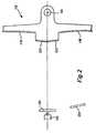
- a further scanner embodimentis shown in Figure 8.
- the beam from a laser 510is shaped by a cylindrical scanning mirror 512 before being directed to an indicia to be read (not shown).
- the cylindrical surface of the scanning mirror 512allows the beam to be shaped, as desired, in the X direction.
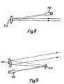
- FIG. 9Another embodiment is shown in Figure 9.
- light from a laser 610impinges upon a first scanning mirror 612 and a second scanning mirror 614. Both of the mirrors have a cylindrical surface, thereby shaping the beam as required in both the X direction and in the Y direction.
- the exact mirror profile in Figures 8 and 9may be chosen according to the beam shaping that is required. It may, for example, in some circumstances be useful to have a toroidal surface rather than a cylindrical surface.
- the shapingmay be carried out by reflecting the light beam from one or more stationary mirrors either after or before the light has impinged upon a scanning element. In its most general form, beam shaping is carried out by reflecting the beam from one or more aplanar surfaces.
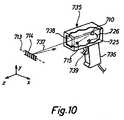
- Figure 10illustrates, as an example, a suitable type of hand-held laser scanner into which any one of the previously described embodiments may be incorporated.
- the specific features incorporated within the scanner of Figure 10differ slightly in detail from the features already described with reference to Figures 1 to 9, but it will of course be understood that any of the embodiments described in connection with Figure 9 could be incorporated within a hand-held scanner of the type shown in Figure 10.
- the scanner of Figure 10comprises a main body 735 having a graspable hand portion 736 which carries a trigger 739.
- a laser module 715Within the body 735 is a laser module 715.
- Light from the laser module 715is arranged to shine onto an oscillating mirror 710, which may for example be a mirror of the form shown in Figure 2, Figures 3, or Figure 5.
- the resulting beam 737passes out of the housing via a window 738.
- the mirror 710is arranged to oscillate in such a way that the beam 737 traces out a scan line 713 across an indicia 714 to be recorded.
- Light reflected back from the indiciapasses through the window 738, is collected by a collecting mirror 726, and is reflected to a photodetector 725.
- the optical signalis then converted into an electrical signal and the features of the indicia 714 determined.
Landscapes
- Physics & Mathematics (AREA)
- Engineering & Computer Science (AREA)
- Electromagnetism (AREA)
- Artificial Intelligence (AREA)
- Toxicology (AREA)
- General Health & Medical Sciences (AREA)
- Health & Medical Sciences (AREA)
- Computer Vision & Pattern Recognition (AREA)
- General Physics & Mathematics (AREA)
- Theoretical Computer Science (AREA)
- Mechanical Optical Scanning Systems (AREA)
- Optical Recording Or Reproduction (AREA)
- Character Input (AREA)
Description
Further embodiments are defined in the dependentclaims.
Claims (11)
- An optical scanner for reading indicia having areas of different lightreflectivity, comprising:wherein the beam shaping optical element (38) of the light source, thescanning optical element (12), and the first and second profiles of the multi-surfacereflector (14) together shape the light beam so that the scanner isadapted to read an indicia at a first distance (32) when the beam is reflectedfrom the first surface (16) and at a second distance (28) when the beam isreflected from the second surface (20);a light source (10, 38) for producing a light beam, the light source including abeam shaping optical element (38);a scanning optical element (12) for receiving the light beam and producing ascanning outgoing light beam therefrom; anda multi-surface reflector (14) having a first surface (16) of a first profile and asecond surface (20) of a second profile,
wherein the multi-surface reflector (14) comprises a fold mirror, the foldmirror being arranged to receive the scanning outgoing light beam and todirect it towards an indicia to be read. - A scanner as claimed in claim 1 in which the fold mirror (14) also collectslight reflected from the indicia to be read, and directs it to a photodetector.
- A scanner as claimed in claim 1 in which the light from the first surface (16)defines a first scan line and light from the second surface (20) defines asecond scan line, the first and second scan lines being in the same directionwith respect to the scanner but adapted for reading an indicia at differentdistances.
- A scanner as claimed in claim 3 in which, in use, the first and second scanlines alternate.
- A scanner as claimed in claim 1 in which the first surface is planar.
- A scanner as claimed in claim 1 in which the second surface is aplanar.
- A scanner as claimed in claim 6 in which the second surface is cylindrical.
- A scanner as claimed in claim 6 in which the second surface is toroidal.
- A scanner as claimed in claim 1 in which the light source (10) is a lasersource and the beam shaping optical element (38) comprises an opticalelement in the path of the light beam emerging from the laser source (10).
- A scanner as claimed in claim 9 in which the optical element comprises alens (38).
- An optical scanner for reading indicia having areas of differing lightreflectivity, the scanner including a movable scanning optical element (12,36) and a multi-surface fold mirror (14) having a first surface of a first profileand a second surface of a second, different, profile, wherein the fold mirror(14) is stationary relative to the movable scanning optical element (12, 36).
Priority Applications (1)
| Application Number | Priority Date | Filing Date | Title |
|---|---|---|---|
| EP02003053AEP1204068A3 (en) | 1995-03-17 | 1996-03-18 | Optical scanners having dual surface optical elements for dual working ranges |
Applications Claiming Priority (2)
| Application Number | Priority Date | Filing Date | Title |
|---|---|---|---|
| US40558595A | 1995-03-17 | 1995-03-17 | |
| US405585 | 1995-03-17 |
Related Child Applications (1)
| Application Number | Title | Priority Date | Filing Date |
|---|---|---|---|
| EP02003053.2Division-Into | 2002-02-12 |
Publications (2)
| Publication Number | Publication Date |
|---|---|
| EP0752680A1 EP0752680A1 (en) | 1997-01-08 |
| EP0752680B1true EP0752680B1 (en) | 2002-08-28 |
Family
ID=23604288
Family Applications (2)
| Application Number | Title | Priority Date | Filing Date |
|---|---|---|---|
| EP02003053AWithdrawnEP1204068A3 (en) | 1995-03-17 | 1996-03-18 | Optical scanners having dual surface optical elements for dual working ranges |
| EP96104236AExpired - LifetimeEP0752680B1 (en) | 1995-03-17 | 1996-03-18 | Optical scanners having dual surface optical elements for dual working ranges |
Family Applications Before (1)
| Application Number | Title | Priority Date | Filing Date |
|---|---|---|---|
| EP02003053AWithdrawnEP1204068A3 (en) | 1995-03-17 | 1996-03-18 | Optical scanners having dual surface optical elements for dual working ranges |
Country Status (4)
| Country | Link |
|---|---|
| US (3) | US5988502A (en) |
| EP (2) | EP1204068A3 (en) |
| CA (3) | CA2170934C (en) |
| DE (1) | DE69623202T2 (en) |
Families Citing this family (28)
| Publication number | Priority date | Publication date | Assignee | Title |
|---|---|---|---|---|
| US5742038A (en) | 1990-09-28 | 1998-04-21 | Symbol Technologies, Inc. | Beam shaping for optical scanners |
| US6382513B1 (en)* | 1991-07-25 | 2002-05-07 | Symbol Technologies, Inc. | Optical scanner with segmented collection mirror |
| US6948662B2 (en) | 1991-07-25 | 2005-09-27 | Symbol Technologies, Inc. | Two-dimensional optical code scanner with scanning pattern having region of greater apparent brightness for assisting alignment of scanning pattern |
| US6170749B1 (en)* | 1995-05-31 | 2001-01-09 | Symbol Technologies, Inc. | Method of scanning indicia using selective sampling |
| US6811086B1 (en)* | 1995-07-20 | 2004-11-02 | Fujitsu Limited | Stand for pivotably mounting an optical reading device |
| US6658144B1 (en)* | 1997-05-23 | 2003-12-02 | Micron Technology, Inc. | Diffraction tomography for monitoring latent image formation |
| NL1006454C2 (en)* | 1997-07-02 | 1999-02-15 | Scantech Bv | Device and method for reading a code on an article. |
| JP3580676B2 (en)* | 1997-08-01 | 2004-10-27 | 富士通株式会社 | Optical scanning device and light source module |
| EP1001297A1 (en) | 1998-11-10 | 2000-05-17 | Datalogic S.P.A. | Optical device and method for focusing a laser beam |
| US6433907B1 (en)* | 1999-08-05 | 2002-08-13 | Microvision, Inc. | Scanned display with plurality of scanning assemblies |
| US6515781B2 (en)* | 1999-08-05 | 2003-02-04 | Microvision, Inc. | Scanned imaging apparatus with switched feeds |
| US7137555B2 (en)* | 2000-02-28 | 2006-11-21 | Psc Scanning, Inc. | Multi-format bar code reader |
| US6612496B1 (en)* | 2000-03-16 | 2003-09-02 | Symbol Technologies, Inc. | Scan module |
| US6761316B2 (en) | 2001-03-27 | 2004-07-13 | Symbol Technologies, Inc. | Compact auto ID reader and radio frequency transceiver data collection module |
| JP2003329944A (en)* | 2002-05-09 | 2003-11-19 | Olympus Optical Co Ltd | Dispersion compensator and dispersion compensation system |
| US20040210277A1 (en)* | 2003-04-16 | 2004-10-21 | Hans Becker | Laser and light emitting diode body irradiator method and apparatus |
| US6880759B2 (en)* | 2003-05-23 | 2005-04-19 | Symagery Microsystems Inc. | Optical reader station |
| US20050245998A1 (en)* | 2004-04-30 | 2005-11-03 | Led Healing Light, Llc | Hand held pulse laser for therapeutic use |
| USD580939S1 (en)* | 2006-08-22 | 2008-11-18 | Hand Held Products, Inc. | Optical reading device |
| US20080117055A1 (en)* | 2006-11-20 | 2008-05-22 | Metrologic Instruments, Inc. | Light activated radio frequency identification conveyance system |
| US8177134B2 (en)* | 2010-07-21 | 2012-05-15 | Hand Held Products, Inc. | Multiple range indicia reader with single trigger actuation |
| US8523074B2 (en)* | 2011-08-26 | 2013-09-03 | Honeywell International Inc. | Bar code imagers |
| US9818009B2 (en)* | 2012-06-01 | 2017-11-14 | The Boeing Company | Multi-spectral enhancements for scan cameras |
| CN103743344B (en)* | 2014-01-20 | 2016-06-15 | 长春理工大学 | Movement locus of object measures system |
| CN103743345B (en)* | 2014-01-20 | 2016-09-21 | 长春理工大学 | Movement locus of object measuring method |
| DE102014105759A1 (en)* | 2014-04-24 | 2015-10-29 | Sick Ag | Camera and method for detecting a moving stream of objects |
| US9530037B1 (en)* | 2015-07-20 | 2016-12-27 | Datalogic ADC, Inc. | Toggling activation of lasers in scanner systems |
| SE1730299A1 (en)* | 2017-11-02 | 2019-05-03 | Gl Dev Ab | Flexible scanner holder |
Family Cites Families (72)
| Publication number | Priority date | Publication date | Assignee | Title |
|---|---|---|---|---|
| US3051051A (en) | 1958-07-11 | 1962-08-28 | Caps Ltd | Optical justifying means |
| GB1040792A (en) | 1964-02-24 | 1966-09-01 | Nat Res Dev | Optical systems for lasers |
| GB1392086A (en) | 1972-03-29 | 1975-04-23 | Rank Organisation Ltd | Lenses |
| US3780270A (en) | 1972-06-20 | 1973-12-18 | Recognition Equipment Inc | Bar/half-bar optical code reader |
| US3790756A (en) | 1972-11-08 | 1974-02-05 | Fmc Corp | Bar code reading circuitry |
| US4360798A (en) | 1978-05-31 | 1982-11-23 | Symbol Technologies, Inc. | Portable laser scanning arrangement for and method of evaluating and validating bar code symbols |
| US4199816A (en) | 1978-06-28 | 1980-04-22 | Humphrey Instruments, Inc. | Optical calibration apparatus and procedure |
| US4369361A (en) | 1980-03-25 | 1983-01-18 | Symbol Technologies, Inc. | Portable, stand-alone, desk-top laser scanning workstation for intelligent data acquisition terminal and method of scanning |
| US4508686A (en) | 1980-12-03 | 1985-04-02 | Probex, Inc. | Film strip for rapid test of a film processor |
| US4570057A (en) | 1981-12-28 | 1986-02-11 | Norand Corporation | Instant portable bar code reader |
| US5047617A (en) | 1982-01-25 | 1991-09-10 | Symbol Technologies, Inc. | Narrow-bodied, single- and twin-windowed portable laser scanning head for reading bar code symbols |
| US4500776A (en) | 1982-11-08 | 1985-02-19 | Vadim Laser | Method and apparatus for remotely reading and decoding bar codes |
| US4555164A (en) | 1983-03-03 | 1985-11-26 | Designs For Vision, Inc. | Anamorphic lens system increasing the field of view for the visually handicapped |
| US4538895A (en) | 1983-03-07 | 1985-09-03 | International Business Machines Corporation | Scanning optical system for use with a semiconductor laser generator |
| US4560862A (en) | 1983-04-26 | 1985-12-24 | Skan-A-Matic Corp. | System for optical scanning over a large depth of field |
| US4652750A (en) | 1983-08-22 | 1987-03-24 | Optel Systems Inc | Optical device for detecting coded symbols |
| US4606660A (en) | 1984-07-12 | 1986-08-19 | System Development Corporation | Printer kit for letter sorting machines |
| US4721860A (en) | 1984-09-20 | 1988-01-26 | Skan-A-Matic Corp. | Laser scanner for bar code reader |
| US4705939A (en) | 1984-09-28 | 1987-11-10 | Rjs Enterprises, Inc. | Apparatus and method for optically measuring bar code dimensions |
| US4641018A (en) | 1984-11-09 | 1987-02-03 | Ncr Corporation | Bar code and reading and decoding device |
| US4795281A (en) | 1984-11-30 | 1989-01-03 | Tohoku Ricoh Co., Ltd. | Self-correcting printer-verifier |
| JPS62111367A (en) | 1985-11-11 | 1987-05-22 | Hitachi Ltd | Barcode reader |
| DE3602008A1 (en)* | 1986-01-23 | 1987-07-30 | Sick Optik Elektronik Erwin | OPTICAL SCANNER WITH A MIRROR WHEEL |
| EP0236738A3 (en) | 1986-02-05 | 1988-12-21 | OMRON Corporation | Input method for reference printed circuit board assembly data to an image processing printed circuit board assembly automatic inspection apparatus |
| US4820911A (en) | 1986-07-11 | 1989-04-11 | Photographic Sciences Corporation | Apparatus for scanning and reading bar codes |
| US5576529A (en) | 1986-08-08 | 1996-11-19 | Norand Technology Corporation | Hand-held optically readable information set reader focus with operation over a range of distances |
| US5640001A (en) | 1986-08-08 | 1997-06-17 | Norand Technology Corporation | Hand-held instant bar code reader having automatic focus control for operation over a range of distances |
| US4860226A (en) | 1986-09-09 | 1989-08-22 | Martin Edward L | Method and apparatus for bar code graphics quality control |
| US4766298A (en)* | 1986-11-10 | 1988-08-23 | Ncr Corporation | Low-profile portable UPC optical scanner |
| US4822986A (en) | 1987-04-17 | 1989-04-18 | Recognition Equipment Incorporated | Method of detecting and reading postal bar codes |
| ATE86402T1 (en) | 1987-04-22 | 1993-03-15 | Abbott Lab | SCANNER AND FORMAT OF AN OPTICAL CODE. |
| DE3725814A1 (en) | 1987-08-04 | 1989-02-16 | Bauerhin I G Elektro Tech | SEAT HEATING FOR INTEGRATED INSTALLATION IN VEHICLE SEATS |
| US4826269A (en) | 1987-10-16 | 1989-05-02 | Spectra Diode Laboratories, Inc. | Diode laser arrangement forming bright image |
| FR2622992B1 (en) | 1987-11-06 | 1990-02-09 | Thomson Semiconducteurs | METHOD FOR READING BAR CODES |
| US5448046A (en)* | 1987-12-28 | 1995-09-05 | Symbol Technologies, Inc. | Arrangement for and method of expediting commercial product transactions at a point-of-sale site |
| US5034904A (en) | 1988-01-27 | 1991-07-23 | Storage Technology Corporation | Vision system illumination calibration apparatus |
| US5170277A (en) | 1988-05-11 | 1992-12-08 | Symbol Technologies, Inc. | Piezoelectric beam deflector |
| US4992649A (en) | 1988-09-30 | 1991-02-12 | United States Postal Service | Remote video scanning automated sorting system |
| US5235167A (en)* | 1988-10-21 | 1993-08-10 | Symbol Technologies, Inc. | Laser scanning system and scanning method for reading bar codes |
| US5600119A (en)* | 1988-10-21 | 1997-02-04 | Symbol Technologies, Inc. | Dual line laser scanning system and scanning method for reading multidimensional bar codes |
| US5229591A (en) | 1988-10-21 | 1993-07-20 | Symbol Technologies, Inc. | Scanning system with adjustable light output and/or scanning angle |
| US4933538A (en) | 1988-10-21 | 1990-06-12 | Symbol Technologies, Inc. | Scanning system with adjustable light output and/or scanning angle |
| US4896026A (en) | 1988-10-31 | 1990-01-23 | Symbol Technologies, Inc. | Laser diode scanner with improved shock mounting |
| US5304788A (en)* | 1988-10-31 | 1994-04-19 | Symbol Technologies, Inc. | Laser diode scanner with enhanced visibility at an aiming distance relative to the reading distance |
| US5280161A (en) | 1988-11-18 | 1994-01-18 | West Electric Company, Ltd. | Apparatus for optically reading a bar code |
| US5064258A (en) | 1988-12-09 | 1991-11-12 | Ricoh Company, Ltd. | Information reading device |
| DE3842333C1 (en) | 1988-12-16 | 1990-04-12 | Daimler-Benz Aktiengesellschaft, 7000 Stuttgart, De | |
| US5073954A (en) | 1989-02-28 | 1991-12-17 | Electrocom Automation, Inc. | Bar code location and recognition processing system |
| US5013895A (en) | 1989-10-23 | 1991-05-07 | Iggulden Jerry R | Personal postnet barcode printers |
| US5067093A (en) | 1990-01-24 | 1991-11-19 | Eastman Kodak Company | Reference reading in an analyzer |
| US5250791A (en) | 1990-04-09 | 1993-10-05 | Symbol Technologies, Inc. | Scanning system with adjustable light output and/or scanning angle |
| JPH03290609A (en) | 1990-04-09 | 1991-12-20 | Ricoh Co Ltd | optical scanning device |
| US5149948A (en)* | 1990-07-16 | 1992-09-22 | Computer Identics | Improved bar code reader system for reading bar codes under high specular reflection conditions with a variety of surface effects |
| US5756982A (en)* | 1990-09-11 | 1998-05-26 | Metrologic Instruments, Inc. | Body-wearable automatic laser scanner with power-conserving control subsystem |
| US5742038A (en) | 1990-09-28 | 1998-04-21 | Symbol Technologies, Inc. | Beam shaping for optical scanners |
| US5081639A (en) | 1990-10-01 | 1992-01-14 | The United States Of America As Represented By The United States Department Of Energy | Laser diode assembly including a cylindrical lens |
| US5200597A (en) | 1991-02-07 | 1993-04-06 | Psc, Inc. | Digitally controlled system for scanning and reading bar codes |
| US5194720A (en) | 1991-04-25 | 1993-03-16 | Eastman Kodak Company | Method and apparatus for performing on-line integrated decoding and evaluation of bar code data |
| US5859417A (en)* | 1991-06-14 | 1999-01-12 | Symbol Technologies, Inc. | Optical scanners having dual surface optical elements for dual working ranges |
| CA2056272C (en)* | 1991-06-14 | 2001-10-16 | Patrick Salatto, Jr. | Combined range laser scanner |
| US5332892A (en) | 1991-07-25 | 1994-07-26 | Symbol Technologies, Inc. | Optical systems for bar code scanners |
| US5179271A (en)* | 1991-09-19 | 1993-01-12 | Ncr Corporation | Compact optical scan pattern generator for bar code reading systems |
| EP0533383A3 (en)* | 1991-09-19 | 1993-04-14 | Ncr International Inc. | Optical scanner apparatus |
| EP0539054A1 (en)* | 1991-10-23 | 1993-04-28 | Ncr International Inc. | Optical scanner apparatus |
| JP2789282B2 (en) | 1992-07-10 | 1998-08-20 | 富士通株式会社 | Optical mark reader |
| US5327451A (en) | 1992-08-07 | 1994-07-05 | Spectra-Physics Scanning Systems, Inc. | Laser diode assembly for laser scanner system |
| JP2826240B2 (en) | 1992-11-16 | 1998-11-18 | 富士通株式会社 | Barcode reader |
| US5484990A (en)* | 1993-12-15 | 1996-01-16 | Ncr Corporation Information Solutions Company | Multiple depth of field laser optical scanner |
| JP3265775B2 (en)* | 1993-12-16 | 2002-03-18 | 株式会社デンソー | Optical information reader |
| US5475208A (en)* | 1994-01-27 | 1995-12-12 | Symbol Technologies, Inc. | Barcode scanner having a dead zone reducing system and a multifocal length collector |
| JP3213669B2 (en)* | 1994-05-30 | 2001-10-02 | 東芝テック株式会社 | Checkout system |
| US5591954A (en) | 1995-02-23 | 1997-01-07 | At&T Global Information Solutions Company | Apparatus and method for equalizing the signal strengths of different scan lines |
- 1996
- 1996-03-04CACA002170934Apatent/CA2170934C/ennot_activeExpired - Fee Related
- 1996-03-04CACA 2580841patent/CA2580841C/ennot_activeExpired - Fee Related
- 1996-03-04CACA002580492Apatent/CA2580492C/ennot_activeExpired - Fee Related
- 1996-03-18EPEP02003053Apatent/EP1204068A3/ennot_activeWithdrawn
- 1996-03-18EPEP96104236Apatent/EP0752680B1/ennot_activeExpired - Lifetime
- 1996-03-18DEDE69623202Tpatent/DE69623202T2/ennot_activeExpired - Fee Related
- 1998
- 1998-01-20USUS09/009,231patent/US5988502A/ennot_activeCeased
- 1999
- 1999-06-09USUS09/328,948patent/US6220514B1/ennot_activeCeased
- 2006
- 2006-03-30USUS11/396,225patent/USRE40102E1/ennot_activeExpired - Fee Related
Also Published As
| Publication number | Publication date |
|---|---|
| EP1204068A3 (en) | 2003-02-19 |
| CA2170934C (en) | 2007-06-19 |
| DE69623202D1 (en) | 2002-10-02 |
| CA2580841C (en) | 2008-08-05 |
| US6220514B1 (en) | 2001-04-24 |
| DE69623202T2 (en) | 2003-05-28 |
| CA2170934A1 (en) | 1996-09-18 |
| CA2580841A1 (en) | 1996-09-18 |
| EP0752680A1 (en) | 1997-01-08 |
| CA2580492A1 (en) | 1996-09-18 |
| USRE40102E1 (en) | 2008-02-26 |
| CA2580492C (en) | 2007-10-09 |
| EP1204068A2 (en) | 2002-05-08 |
| US5988502A (en) | 1999-11-23 |
Similar Documents
| Publication | Publication Date | Title |
|---|---|---|
| EP0752680B1 (en) | Optical scanners having dual surface optical elements for dual working ranges | |
| US5859417A (en) | Optical scanners having dual surface optical elements for dual working ranges | |
| US5361158A (en) | Multiple source optical scanner | |
| US5945658A (en) | Automatically selectable range laser scanner | |
| US5202784A (en) | Optical system for data reading applications | |
| US5969323A (en) | Noise-reduced electro-optical readers with optical bandpass filter | |
| USRE40101E1 (en) | Electro-optical scanner having selectable scan pattern | |
| US6188500B1 (en) | Method for generating multiple scan lines in a thin scanner | |
| JP3056590B2 (en) | Optical scanner with increased depth of focus | |
| EP0449490A1 (en) | Optical scanning apparatus | |
| US5484990A (en) | Multiple depth of field laser optical scanner | |
| US6543693B1 (en) | Bar code readers using surface emitting laser diode | |
| EP0575894B1 (en) | Retro-reflective scanner with return path free of collection optics | |
| EP0895176B1 (en) | Optical scanner and light source module | |
| EP0553504A1 (en) | Optical scanning system comprising optical chopper | |
| WO2008042777A2 (en) | Mems-based electro-optical reader and method with extended working range | |
| WO2018014521A1 (en) | Multi-directional bar code scanning device having multiple laser emitters matched with single photosensitive receiver | |
| EP3031007B1 (en) | Laser light beam scanning device for reading coded information | |
| JP3866321B2 (en) | Optical scanner | |
| US20090001168A1 (en) | Barcode scanner including a multi-tasking pattern mirror | |
| EP1110167B1 (en) | Quasi-coaxial optical bar code reader | |
| US5530233A (en) | Bar code scanner with quasi-retroreflective light collection | |
| JP2889754B2 (en) | Optical scanning device | |
| KR930005044Y1 (en) | Barcode Laser Scanner Optics | |
| JPH02101595A (en) | Bar-code scanner |
Legal Events
| Date | Code | Title | Description |
|---|---|---|---|
| PUAI | Public reference made under article 153(3) epc to a published international application that has entered the european phase | Free format text:ORIGINAL CODE: 0009012 | |
| AK | Designated contracting states | Kind code of ref document:A1 Designated state(s):CH DE FR GB IT LI NL | |
| 17P | Request for examination filed | Effective date:19970708 | |
| 17Q | First examination report despatched | Effective date:20000322 | |
| GRAG | Despatch of communication of intention to grant | Free format text:ORIGINAL CODE: EPIDOS AGRA | |
| GRAG | Despatch of communication of intention to grant | Free format text:ORIGINAL CODE: EPIDOS AGRA | |
| GRAH | Despatch of communication of intention to grant a patent | Free format text:ORIGINAL CODE: EPIDOS IGRA | |
| RAP1 | Party data changed (applicant data changed or rights of an application transferred) | Owner name:SYMBOL TECHNOLOGIES, INC. | |
| GRAH | Despatch of communication of intention to grant a patent | Free format text:ORIGINAL CODE: EPIDOS IGRA | |
| GRAA | (expected) grant | Free format text:ORIGINAL CODE: 0009210 | |
| AK | Designated contracting states | Kind code of ref document:B1 Designated state(s):CH DE FR GB IT LI NL | |
| REG | Reference to a national code | Ref country code:GB Ref legal event code:FG4D | |
| REG | Reference to a national code | Ref country code:CH Ref legal event code:EP | |
| REF | Corresponds to: | Ref document number:69623202 Country of ref document:DE Date of ref document:20021002 | |
| ET | Fr: translation filed | ||
| REG | Reference to a national code | Ref country code:CH Ref legal event code:NV Representative=s name:RIEDERER HASLER & PARTNER PATENTANWAELTE AG | |
| PLBE | No opposition filed within time limit | Free format text:ORIGINAL CODE: 0009261 | |
| STAA | Information on the status of an ep patent application or granted ep patent | Free format text:STATUS: NO OPPOSITION FILED WITHIN TIME LIMIT | |
| 26N | No opposition filed | Effective date:20030530 | |
| PGFP | Annual fee paid to national office [announced via postgrant information from national office to epo] | Ref country code:NL Payment date:20070304 Year of fee payment:12 | |
| PGFP | Annual fee paid to national office [announced via postgrant information from national office to epo] | Ref country code:GB Payment date:20070314 Year of fee payment:12 Ref country code:CH Payment date:20070314 Year of fee payment:12 | |
| PGFP | Annual fee paid to national office [announced via postgrant information from national office to epo] | Ref country code:DE Payment date:20070315 Year of fee payment:12 | |
| PGFP | Annual fee paid to national office [announced via postgrant information from national office to epo] | Ref country code:IT Payment date:20070525 Year of fee payment:12 | |
| PGFP | Annual fee paid to national office [announced via postgrant information from national office to epo] | Ref country code:FR Payment date:20070308 Year of fee payment:12 | |
| REG | Reference to a national code | Ref country code:CH Ref legal event code:PL | |
| GBPC | Gb: european patent ceased through non-payment of renewal fee | Effective date:20080318 | |
| PG25 | Lapsed in a contracting state [announced via postgrant information from national office to epo] | Ref country code:NL Free format text:LAPSE BECAUSE OF NON-PAYMENT OF DUE FEES Effective date:20081001 | |
| NLV4 | Nl: lapsed or anulled due to non-payment of the annual fee | Effective date:20081001 | |
| REG | Reference to a national code | Ref country code:FR Ref legal event code:ST Effective date:20081125 | |
| PG25 | Lapsed in a contracting state [announced via postgrant information from national office to epo] | Ref country code:LI Free format text:LAPSE BECAUSE OF NON-PAYMENT OF DUE FEES Effective date:20080331 Ref country code:DE Free format text:LAPSE BECAUSE OF NON-PAYMENT OF DUE FEES Effective date:20081001 Ref country code:CH Free format text:LAPSE BECAUSE OF NON-PAYMENT OF DUE FEES Effective date:20080331 | |
| PG25 | Lapsed in a contracting state [announced via postgrant information from national office to epo] | Ref country code:FR Free format text:LAPSE BECAUSE OF NON-PAYMENT OF DUE FEES Effective date:20080331 | |
| PG25 | Lapsed in a contracting state [announced via postgrant information from national office to epo] | Ref country code:GB Free format text:LAPSE BECAUSE OF NON-PAYMENT OF DUE FEES Effective date:20080318 | |
| PG25 | Lapsed in a contracting state [announced via postgrant information from national office to epo] | Ref country code:IT Free format text:LAPSE BECAUSE OF NON-PAYMENT OF DUE FEES Effective date:20080318 |