EP0751794B1 - Disposable fluid infusion pumping chamber cassette having a push button flow stop thereon - Google Patents
Disposable fluid infusion pumping chamber cassette having a push button flow stop thereonDownload PDFInfo
- Publication number
- EP0751794B1 EP0751794B1EP95920406AEP95920406AEP0751794B1EP 0751794 B1EP0751794 B1EP 0751794B1EP 95920406 AEP95920406 AEP 95920406AEP 95920406 AEP95920406 AEP 95920406AEP 0751794 B1EP0751794 B1EP 0751794B1
- Authority
- EP
- European Patent Office
- Prior art keywords
- cassette
- pump
- pumping chamber
- pressure monitoring
- fluid
- Prior art date
- Legal status (The legal status is an assumption and is not a legal conclusion. Google has not performed a legal analysis and makes no representation as to the accuracy of the status listed.)
- Expired - Lifetime
Links
- 239000012530fluidSubstances0.000titleclaimsabstractdescription61
- 238000005086pumpingMethods0.000titleclaimsabstractdescription50
- 238000001802infusionMethods0.000titledescription8
- 238000012544monitoring processMethods0.000claimsabstractdescription40
- 230000002093peripheral effectEffects0.000claimsdescription24
- 230000000903blocking effectEffects0.000claims2
- 230000000295complement effectEffects0.000claims2
- 238000011144upstream manufacturingMethods0.000claims1
- 239000012528membraneSubstances0.000abstract3
- 230000037452primingEffects0.000abstract1
- 238000001514detection methodMethods0.000description5
- 238000006073displacement reactionMethods0.000description2
- 230000005484gravityEffects0.000description2
- 230000007246mechanismEffects0.000description2
- 230000003213activating effectEffects0.000description1
- 239000012190activatorSubstances0.000description1
- 230000006978adaptationEffects0.000description1
- 239000003814drugSubstances0.000description1
- 229940079593drugDrugs0.000description1
- 238000010348incorporationMethods0.000description1
- 238000003780insertionMethods0.000description1
- 230000037431insertionEffects0.000description1
- 238000009434installationMethods0.000description1
- 238000001990intravenous administrationMethods0.000description1
- 239000007788liquidSubstances0.000description1
- 238000004519manufacturing processMethods0.000description1
- 238000012806monitoring deviceMethods0.000description1
- 230000003389potentiating effectEffects0.000description1
- 230000000717retained effectEffects0.000description1
- 239000003351stiffenerSubstances0.000description1
- 238000003466weldingMethods0.000description1
Images


Classifications
- F—MECHANICAL ENGINEERING; LIGHTING; HEATING; WEAPONS; BLASTING
- F04—POSITIVE - DISPLACEMENT MACHINES FOR LIQUIDS; PUMPS FOR LIQUIDS OR ELASTIC FLUIDS
- F04B—POSITIVE-DISPLACEMENT MACHINES FOR LIQUIDS; PUMPS
- F04B43/00—Machines, pumps, or pumping installations having flexible working members
- F04B43/02—Machines, pumps, or pumping installations having flexible working members having plate-like flexible members, e.g. diaphragms
- A—HUMAN NECESSITIES
- A61—MEDICAL OR VETERINARY SCIENCE; HYGIENE
- A61M—DEVICES FOR INTRODUCING MEDIA INTO, OR ONTO, THE BODY; DEVICES FOR TRANSDUCING BODY MEDIA OR FOR TAKING MEDIA FROM THE BODY; DEVICES FOR PRODUCING OR ENDING SLEEP OR STUPOR
- A61M5/00—Devices for bringing media into the body in a subcutaneous, intra-vascular or intramuscular way; Accessories therefor, e.g. filling or cleaning devices, arm-rests
- A61M5/14—Infusion devices, e.g. infusing by gravity; Blood infusion; Accessories therefor
- A61M5/142—Pressure infusion, e.g. using pumps
- A61M5/14212—Pumping with an aspiration and an expulsion action
- A61M5/14224—Diaphragm type
- F—MECHANICAL ENGINEERING; LIGHTING; HEATING; WEAPONS; BLASTING
- F04—POSITIVE - DISPLACEMENT MACHINES FOR LIQUIDS; PUMPS FOR LIQUIDS OR ELASTIC FLUIDS
- F04B—POSITIVE-DISPLACEMENT MACHINES FOR LIQUIDS; PUMPS
- F04B43/00—Machines, pumps, or pumping installations having flexible working members
- F04B43/0009—Special features
- F04B43/0054—Special features particularities of the flexible members
- A—HUMAN NECESSITIES
- A61—MEDICAL OR VETERINARY SCIENCE; HYGIENE
- A61M—DEVICES FOR INTRODUCING MEDIA INTO, OR ONTO, THE BODY; DEVICES FOR TRANSDUCING BODY MEDIA OR FOR TAKING MEDIA FROM THE BODY; DEVICES FOR PRODUCING OR ENDING SLEEP OR STUPOR
- A61M2205/00—General characteristics of the apparatus
- A61M2205/12—General characteristics of the apparatus with interchangeable cassettes forming partially or totally the fluid circuit
- A61M2205/128—General characteristics of the apparatus with interchangeable cassettes forming partially or totally the fluid circuit with incorporated valves
- A—HUMAN NECESSITIES
- A61—MEDICAL OR VETERINARY SCIENCE; HYGIENE
- A61M—DEVICES FOR INTRODUCING MEDIA INTO, OR ONTO, THE BODY; DEVICES FOR TRANSDUCING BODY MEDIA OR FOR TAKING MEDIA FROM THE BODY; DEVICES FOR PRODUCING OR ENDING SLEEP OR STUPOR
- A61M39/00—Tubes, tube connectors, tube couplings, valves, access sites or the like, specially adapted for medical use
- A61M39/22—Valves or arrangement of valves
- A61M39/28—Clamping means for squeezing flexible tubes, e.g. roller clamps
- A61M39/281—Automatic tube cut-off devices, e.g. squeezing tube on detection of air
- Y—GENERAL TAGGING OF NEW TECHNOLOGICAL DEVELOPMENTS; GENERAL TAGGING OF CROSS-SECTIONAL TECHNOLOGIES SPANNING OVER SEVERAL SECTIONS OF THE IPC; TECHNICAL SUBJECTS COVERED BY FORMER USPC CROSS-REFERENCE ART COLLECTIONS [XRACs] AND DIGESTS
- Y10—TECHNICAL SUBJECTS COVERED BY FORMER USPC
- Y10S—TECHNICAL SUBJECTS COVERED BY FORMER USPC CROSS-REFERENCE ART COLLECTIONS [XRACs] AND DIGESTS
- Y10S128/00—Surgery
- Y10S128/12—Pressure infusion
Definitions
- a typical positive displacement infusion pump systemincludes a pump driver device and a disposable cassette.
- the disposable cassettewhich is adapted to be used only for a single patient and for one fluid delivery cycle, is typically a small plastic unit having an inlet and an outlet respectively connected through flexible tubing to the fluid supply container and to the patient receiving the infusion.
- the cassetteincludes a pumping chamber, with the flow of fluid through the chamber being controlled by a plunger or piston activated in a controlled manner by the driver device.
- the cassette chambermay have one wall there formed by a flexible diaphragm which is reciprocated by the plunger and the driver to cause fluid to flow.
- the pump driver deviceincludes the plunger or piston for controlling the flow of fluid into and out of the pumping chamber in the cassette, and it also includes control mechanisms to assure that the fluid is delivered to the patient at a pre-set rate, in a pre-determined manner, and only for a particular preselected time or total dosage.
- the pump driver devicemay also include pressure sensing and other fluid flow monitoring devices, as well as valving members for opening and closing various passages in the cassette including the inlet and outlet passages of the pumping chamber.
- a disposable pumping chamber cassette of the prior artcan be readily and inexpensively manufactured in three pieces.
- the size of the prior art cassetteenables the incorporation of a multiplicity of control and monitoring functions.
- the prior art cassetteincludes, for example, pressure monitoring, air bubble detection monitoring, adaptation to multiple inputs, and leak detection monitoring, all of which functions could be performed without modifying the basic cassette structure.
- a pump cassette according to the precharacterizing portion of claim 1is known from EP-A-0 293 592.
- DE-AS-2 142 702 and US-A-4 411 603describe pumping devices for medical use including one-way check valves.
- US-A-3 416 461relates to diaphragm pump including a diaphragm stem with peripheral ribs for minimizing possibility of leakage.
- FR-A-2 352 996describes an intravenous infusion pump with respective proximal and distal pressure monitoring chambers.
- the disposable fluid infusion pumping chamber cassette of the present inventionhas its genesis in the cassette of the prior art, the present cassette is simpler in structure and in operation and presents a substantially smaller cassette profile, places such control and monitoring functions as air bubble detection monitoring and leak detection monitoring off the cassette to further simplify and shrink the size of the cassette, and provides a pushbutton flow stop to further control fluid delivery through the improved cassette of the present invention, as defined in the appended claims.
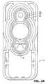
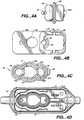
- a pumping cassette 10 of the present inventionis illustrated in Figures 1 - 6.
- the cassette 10includes a rigid face member 12 and a rigid back member 14 with an elastomeric member 16 positioned between.
- Face member 12has a plunger opening 18 with the elastomeric member 16 extending across the opening.
- Behind plunger opening 18, in the back member 14,is an enlarged recess 20, which forms the lower fluid reservoir of a pumping chamber 22.
- a flow stop 24comprising a rockable switch body 25 is mounted on the face member 12.
- Switch body 25is mounted on a shaft 26 which protrudes from opposite sides of the switch body 24 and further includes at an upper face thereof a concave switch actuator 27 and a convex switch actuator 28.
- a leg 29extends below the concave switch actuator 27. Disposed at a lower end of leg 29 of concave switch actuator 27 is a stop 29a. Disposed at a lower outer end of the convex switch actuator 28 of a midpoint thereof is a crown member 30 having,an upper end 30a and a lower end 30b.
- Face member 12is a generally rectangularly shaped body 31 having opposite side walls 32a, 32b and end walls 34a and 34b. Each juncture of a side wall 32a, 32b with a respective end wall 34a, 34b is rounded, as best seen in the plan view of Figure 4B. Face member 12 is about 4.3 centimeters ("cm") long and 1.8 cm wide. An open section 35, at the distal end of the face member 12, is almost square, being slightly longer, at about 2.1 cm, than its width. Distal end wall 34b, adjacent the open section 35 is about 1.1 cm high, about twice the height of proximal end wall 34a (0.55 cm).
- Side walls 32a, 32bare as high as distal end wall 34b at the juncture therebetween, but step down to the level of proximal end wall 34a in two steps 36 and 37.
- the first step 36is at about the mid-point of the open section 35
- the second step 37is at an inner end 35a of the open section.
- Upper face 38which is at the height of proximal end wall 34a, is essentially closed from the riser 37a of the second step 37 to the proximal end wall.
- the open section 35includes opposite interior flanges 39 which extend from the upper face 37b of second step 37 at opposite ends thereof along side walls 32a, 32b to terminate at distal end wall 34b at the inner side thereof.
- Upper face 37balso includes a semi-circular cutout 40 at a mid-portion thereof, the cutout 40 generally centered along the longitudinal axis of face member 12,. with an open face of the cut out 40 opening into section 35.
- openings 41Provided in opposite interior flanges 39 generally at respective mid-portions thereof are openings 41 further defined by downwardly extending sets of rails or guides 42 provided at opposite peripheral edges of each opening 39 and integrally molded into side walls 32a, 32b.
- Each rail or guide of each set of rails or guides 42terminates at a lower end in a detent 42a.
- the upper face 38 of face member 12extends from the bottom of second step 37 to proximal end wall 34a to close upper face 38 except for a plunger opening 18 and a proximal sensor opening 18a disposed between the opening 18 and end wall 32a.
- Underlying upper face 38is an integral face elliptic member 43 centrally disposed about the plunger opening 18 and extending outwardly therefrom toward opposite end walls 32a, 32b to encompass the proximal sensor opening 18a and a distal sensor opening partially defined by the cut out 40 provided at the inner end of the upper face 37b of second step 37.
- An outer peripheral ridge 43a of elliptic member 43 and a second peripheral ridge 43c inset therefromdefine a peripheral channel 43b therebetween.
- a portion of face elliptic member 43 opposite the cut out opening 40 in face 37b of second step 37is spaced from the face of step 37.
- Elastomeric member 16is a molded flexible elastomeric member also somewhat elliptic in configuration, which conforms generally to the shape of the face elliptic member 43 at the underside of upper face 38 of face member 12.
- Elastomeric member 16includes a diaphragm 17 having a central plunger engaging diaphragm portion 44 and sensor engaging diaphragm portions 45, 46 at opposite ends of portion 44.
- the elastomeric member 16is symmetric with respect to its upper and lower surfaces to define similar peripheral ridges 47a and 47c with a similar peripheral groove 47b therebetween, on the underside of the elastomeric member. Ridge 47a, groove 47b and ridge 47c encompass diaphragm portions 44, 45 and 46.
- An end tab 48is integrally molded into the elastomeric member 16 at a distal end thereof to ensure correct placement of the member in the cassette 10 during assembly.
- Flapper valves 49a and 49bare integrally molded into the underside of elastomeric member 16 as best seen in Figures 3B, and 4c. Note proximal sensing diaphragm portion 45 is smaller than distal sensing diaphragm portion 46.
- Flapper valve 49ais disposed outside proximal sensing diaphragm portion 45 and within the central plunger engaging diaphragm portion 44 and flapper valve 49b is disposed within distal sensing diaphragm portion 46, to make the sensing areas of diaphragm portions 45, 46 approximately equal.
- Base member 14includes a generally box-like section 53 of rectangular configuration having a bottom wall 50, side walls 51a, 51b and end walls 52a, 52b.
- the juncture of side walls 51a, 51b and end walls 52a, 52bdefine a box section 53 and are rounded to conform the shape of the box section to the exterior shape of face member 12.
- Box section 53 of base member 14is about 4.5 cm long and 2.0 cm wide.
- the side walls 51a, 51b and the end walls 52a, 52bare of uniform height (0.9 cm).
- the bottom wall 50carries a base elliptic member 54 similar in shape to the face elliptic member 43 on face member 12, and generally conforming to the shape of the elastomeric member 16.
- the base elliptic member 54includes an outer peripheral ridge 54a and a second peripheral ridge 54c somewhat lower in height and inset therefrom, to define a channel 54b therebetween.
- the structure of base elliptic member 54conforms generally the structure of face elliptic member 43.
- the interior of base elliptic member 54includes a large pumping chamber 22.
- Two smaller pressure monitoring chambersi.e., a proximal pressure monitoring chamber 56 and a distal pressure monitoring chamber 57, are connected to opposite ends of the pumping chamber 22 and disposed along the longitudinal axis of the cassette 10.
- proximal end wall 52a and proximal pressure monitoring chamber 56Connected between proximal end wall 52a and proximal pressure monitoring chamber 56 is a tubular proximal pumping chamber inlet 59 molded into the bottom wall 50 of base member 14.
- a similar distal pumping chamber outlet 60is connected between distal pressure monitoring chamber 57 and distal end wall 52b.
- a cassette inlet 61is molded into proximal end wall 52a of the base member 14 and connected to the pumping chamber inlet 59.
- a cassette outlet 62is molded into distal end wall 52b and connected to pumping chamber outlet 60.
- Stiffeners or stiffening walls 63extend from each of the end walls 52a, 52b to respective fluid inlet and fluid outlet 61 and 62 to provide a triangular support structure at each end of the base member 14 which retains and supports the inlet and outlet 61 and 62 mounted on the base member 14. Note also that the center pumping chamber 22 and the proximal and distal pressure monitoring chambers 56, 57 do not extend below the bottom of the side walls 51a, 51b of the base member 14.
- cradle supports 64mounted on the bottom wall 50 on the opposite sides of the pumping chamber outlet 60.
- Cradle supports 64are generally aligned with the cradle guides 42 of face member 12 when the base member 14 and the face member 12 are assembled.
- Switch stop 65is mounted on the pumping chamber outlet 60 distal of the cradle supports 64.
- Disposed in the side walls of the base member 14are notches 71.
- the assembled cassetteis shown in Figures 5 and 6 in which the base member 14 receives the elastomeric member 16 which is then overlaid by the face member 12. Finally the flow stop 24 is inserted into the opening 35 in the face member 12 with the shaft 26 lowered along the cradle guides 42 to mount the flow stop 24 on opposite cradle supports 64 provided on the bottom wall 50 of base member 14.
- the base member 14receives the elastomeric member 16 on base elliptic member 54 as follows.
- Base elliptic member 54 of base member 14receives elastomeric member 16, with outer peripheral ridge 54a of elliptic member 54 engaging the lower groove 47b of elastomeric member 16, and the outer ridge 47a of the elastomeric member disposed outside the outer ridge 54a of base elliptic member 54.
- Inner peripheral ridge 54c of member 54traps inner lower ridge 47c of elastomeric member 16 within channel 54b of member 54.
- plunger opening 18 of the face member 12is aligned with the recess 20 of the base member 14.
- the flow stop 24is installed in the cassette 10 as follows.
- Switch body 25is installed in the opening 35 of the face member 12 with shaft 26 sliding along cradle guides 42 of the face member 12 until the shaft 26 is disposed in the cradle supports 64 provided on the bottom wall 50 of the base member 14.
- each of the cradle guides 42includes an inwardly directed detent 42a at a respective lower end thereof so that in the installed position of the flow stop 24, shaft 26 slides past the detents 42a of the cradle guides 42 to be trapped between the lower ends of cradle guides 42 and the respective opposite cradle supports 64 of the base member 14.
- the flow stop 24is rotated clockwise to dispose the concave switch actuator 27 below the convex switch actuator 28 in an open position of the flow stop for cassette 10 with check valves or flapper valves 49a and 49b slightly open.
- the cassette 10is in a free flow condition; i.e., the force of gravity on flapper valves 49a, 49b provided by fluid flowing into the cassette is sufficient to open the flapper valves and enable fluid flow through the cassette.
- lower leg stop 29a of lower leg 29 of the flow stop 24is disposed below detent 35b provided at a lower inner edge of distal end wall 34b of the face member 12 to hold the flow stop 24 in the open position of Figure 5.
- switch stop 65engages the concave switch actuator 27 to prevent further rotation of flow stop 24 about shaft 26.
- FIG. 7shows a pump 69 including a pump housing 70 carrying therein a pump driver 72 including a plunger 73, a proximal pressure sensor 74 and a distal.pressure sensor 75.
- the cassette 10when installed in the pump housing 70, is held in place as by snaps 71a which engage the notches 71 in the side walls of the base member 14 to retain the cassette in the pump 69.
- the cassette 10thus is mounted on the pump 69, with no door closing over the cassette or activating the cassettes. Because there is no pump door to protect the cassette 10, it is desirable to place all active cassette elements, such as plunger opening 18 and flow stop 24 at the pump/cassette interface.
- the flow stop 24thus operates as an auxiliary flow control member in conjunction with flapper valves 49a, 49b when the cassette 10 is loaded into the pump 69.
- the operation of the pump driver 72 when the cassette 10 is installed in the pump housing 70is as follows.
- the plunger 73is engaged with and compresses the central portion 44 of the diaphragm of elastomeric member 16 during both the fluid inlet and the fluid discharge portions of the pumping cycle.
- the plunger 73is at the upper end of its stroke and the distal pressure sensor 75 engages upper end 30a of crown member 30 of the flow stop 24 to sense the pressure of fluid flowing through the fluid path of the cassette from the cassette the inlet 61 to the cassette outlet 62.
- the intent of the present inventionis to provide a simple, easily made disposable fluid pump cassette adaptable to a driver mechanism such as used in more sophisticated cassettes.
- the flow stop 24provides the cassette 10 simple means for both controlling fluid flow and for measuring fluid pressure.
- the present cassettedoes not require the extensive valving associated with the inlet and outlet of the cassette as required in prior art cassettes and the in-cassette air detection function for the present cassette is placed externally of the cassette, as for example on respective inlet and outlet lines of the cassette.
- the present cassetteoffers a simpler, smaller, less expensive, and less complicated alternative to the complex and larger cassettes of the prior art.
Landscapes
- Engineering & Computer Science (AREA)
- Health & Medical Sciences (AREA)
- General Engineering & Computer Science (AREA)
- Mechanical Engineering (AREA)
- Biomedical Technology (AREA)
- Veterinary Medicine (AREA)
- Hematology (AREA)
- Life Sciences & Earth Sciences (AREA)
- Animal Behavior & Ethology (AREA)
- General Health & Medical Sciences (AREA)
- Public Health (AREA)
- Heart & Thoracic Surgery (AREA)
- Anesthesiology (AREA)
- Vascular Medicine (AREA)
- Infusion, Injection, And Reservoir Apparatuses (AREA)
- Reciprocating Pumps (AREA)
- Containers And Packaging Bodies Having A Special Means To Remove Contents (AREA)
- External Artificial Organs (AREA)
Abstract
Description
Stiffeners or stiffening
Cradle supports 64 are generally aligned with the cradleguides 42 of
Claims (33)
- A pump cassette (10), adapted to be driven by a pump driver (72) having a plunger(73), comprising:characterized in that the auxiliary flow control member (24) is selectively operatable inone of a first position and a second position as a function of the position of the auxiliary flowcontrol member (24), operation of the auxiliary flow control member (24) in the first positionenabling fluid flow freely through the cassette (10) and operation of the auxiliary flow controlmember (24) in the second position actuating the at least one outlet flow control member (49b) toblock fluid flow through the cassette (10).a cassette inlet (61), a cassette outlet (62) and a fluid path therebetween;a rigid face member (12);a rigid base member (14) having an enlarged recess (20) forming a pumping chamber(22) along the fluid path;an elastomeric member (16) positioned between the face and base members (12, 14); therigid face member (12) including a plunger opening (18) therethrough opposite the pumpingchamber (22) to permit the passage of the plunger (73) to control the flow of fluid through thepumping chamber (22);at least one inlet and at least one outlet flow control member (49a, 49b) provided on thecassette (10) for engagement with the rigid base member (14) to control fluid flow through thecassette (10); andan auxiliary flow control member (24) provided on the elastomeric member (16),
- The pump cassette as claimed in claim 1 wherein the at least one inlet flow controlmember is mounted adjacent the plunger opening (18) and comprises a first one-way check valve(49a) provided in the fluid path proximal to the plunger opening (18), and wherein the at leastone outlet flow control member comprises a second one-way check valve (49b) provided in thefluid path distal to the plunger opening (18); the cassette (10) adapted to open the first one-waycheck valve (49a) and close the second one-way check valve (49b) when the plunger (73), inengagement with the elastomeric member (16), moves away from the rigid base member (14) toadmit fluid into the pumping chamber (22), and close the first one-way check valve (49a) andopen the second one-way check valve (49b) when the plunger (73) engaging the elastomericmember (16) moves toward the rigid base member (14) to discharge fluid from the pumpingchamber (22).
- The pump cassette as claimed in claim 2 wherein the first and second one-way checkvalves (49a, 49b) comprise flapper valves (49a, 49b) integrally molded into the elastomericmember (16).
- The pump cassette as claimed in claim 3 wherein the elastomeric member (16)includes an outer peripheral ridge (47a) and an inner peripheral ridge (47c) spaced therefrom todefine a channel (47b) therebetween, the respective ridges and channel (47a, 47b, 47c)surrounding a central diaphragm portion (17) of the elastomeric member (16) with the flappervalves (49a, 49b) so placed on the central diaphragm portion (17) as to define a central plungerportion (44) and respective proximal and distal pressure monitoring portions (45, 46) of thecentral diaphragm portion (17).
- The pump cassette as claimed in claim 4 wherein the flapper valves (49a, 49b) areplaced at the side of the elastomeric member (16) facing the rigid base member (14) to disposethe proximal flapper valve (49a) within the pumping chamber (22), and the distal flapper valve(49b) outside the pumping chamber (22), with the proximal and distal pressure monitoringportions (45, 46) of the central diaphragm portion (17) so formed as to make the respectiveproximal and distal monitoring areas of the central diaphragm portion (17) approximately equalin size.
- The pump cassette as claimed in one or more of claims 1-5 wherein the auxiliary flowcontrol member comprises a flow stop (24) mounted on the cassette distal of the plunger opening(18), the flow stop (24) including a switch body (25) and a central shaft (26) extending throughthe switch body (25) to protrude on opposite sides thereof, the central shaft (26) to be supportedon the rigid base member (14) to enable a rocking movement, the switch body (25) rockableabout the central shaft (26) on an axis of the cassette (10) between the first position enablingfluid flow through the cassette (10) and the second position blocking fluid flow therethrough.
- The pump cassette as claimed in claim 6 wherein the central shaft (26) of the flowstop (24) is mounted on cradle supports (64) disposed on opposite sides of the cassette outlet (62)provided on the rigid base member (14) of the cassette (10).
- The pump cassette as claimed in claim 7 wherein the switch body (25) comprises twoengageable portions including a convex switch actuator (28) disposed on one side of the centralshaft (26) and a concave switch actuator (27) disposed on an opposite side of the central shaft (26) for rockable movement about the central shaft (26) between the first and second positions.
- The pump cassette as claimed in claim 8 wherein the concave switch actuator (27)includes an outer leg (29) having a detent member (29a) provided at a lower end of the outer leg(29) for engagement with a complementary detent (35a) on a distal end wall (34b) of the rigidface member (12).
- The pump cassette as claimed in claim 9 wherein the concave switch actuator (27)includes a crown (30) disposed at an extremity thereof, with one end (30b) of the crown (30)engaging a pressure monitoring portion of a diaphragm of the elastomeric member (16) of thecassette (10), and an opposite end (30b) of the crown (30) adapted to engage a pressure sensor(74) associated with the pump driver (72), to monitor fluid pressure when the cassette (10) isinstalled in a pump (69).
- The pump cassette as claimed in claim 10 wherein the cassette (10) includes a stop(65) underlying the flow stop (24) to engage the switch body (25) to limit movement of the flowstop (24).
- The pump cassette as claimed in claim 1 further including pressure monitoringmeans to monitor the fluid pressure in the cassette (10).
- The pump cassette as claimed in claim 12 wherein the pressure monitoring meansincludes at least one sensor opening (18a, 40) through the rigid face member (12) adapted toreceive a pressure monitoring member (74, 75) associated with the pump driver (72).
- The pump cassette as claimed in claim 13 wherein the pressure monitoring meansincludes a recess (56, 57) in the rigid base member (14) opposite the at least one sensor opening(18a, 40) and a portion of the elastomeric member (16) overlies the recess (56, 57) in the rigidbase member (14) opposite the at least one sensor opening (18a, 40) to define a pressuremonitoring chamber (56, 57) of the cassette (10).
- The pump cassette as claimed in claim 14 wherein the pressure monitoring meansincludes a distal pressure monitoring chamber (57) located along the portion of the fluid paththrough the cassette (10) downstream of the pumping chamber (22) and a proximal pressuremonitoring chamber (56) located along the portion of the fluid path for the cassette (10) upstream of the pumping chamber (22).
- The pump cassette as claimed in claim 15 including a pumping chamber inlet (59)connected at a proximal end to the cassette inlet (61) and at a distal end to the proximal pressuremonitoring chamber (56) and a pumping chamber outlet (60) connected between the distal end ofthe distal pressure monitoring chamber (57) and the cassette outlet (62).
- The pump cassette as claimed in claim 16 wherein the auxiliary flow controlmember (24) overlies the pumping chamber outlet (60) to position the pressure monitoringmember (75) in engagement with a portion of the elastomeric member (16) overlying the distalpressure monitoring chamber (57), to monitor the pressure of fluid flowing from the pumpingchamber (22) to the cassette outlet (62).
- The pump cassette as claimed in claim 17 wherein stiffening walls (63) are providedbetween the cassette inlet and outlet (61, 62) and the rigid base member (14) to stabilize thecassette inlet and outlet (61, 62) with respect to the rigid base member (14).
- The pump cassette as claimed in claim 18 wherein cradle supports (64) are disposedon opposite sides of the pumping chamber outlet (60) of the rigid base member (14), to supportthe auxiliary flow control member (24) for movement about a central shaft (26) extendingthrough a switch body (25) to protrude on opposite sides thereof, the central shaft (26) to besupported on the rigid base member (14) to enable a rocking movement, the switch body (25)rockable about the central shaft (26) on an axis of the cassette (10) between an open positionenabling fluid flow through the cassette (10) and an engaged position blocking fluid flowtherethrough.
- The pump cassette as claimed in claim 19 wherein a switch stop (65) is disposed onthe outlet channel of the rigid base member (14) to limit movement of the auxiliary flow controlmember (24).
- The pump cassette as claimed in claim 1 wherein a generally elliptic engageable faceportion (43) underlies a proximal section of the rigid face member (12) and includes an outerperipheral ridge (43a) and an inner peripheral ridge (43c) displaced inwardly therefrom to definea channel (43b) therebetween, the elastomeric member (16) comprises a member (47) of agenerally elliptic shape having an outer peripheral ridge (47a), an inner peripheral ridge (47c) displaced inwardly therefrom to define a peripheral channel (47b) therebetween on opposite sidesthereof, and the rigid base member (14) includes a generally elliptic engageable base portion (54)disposed therein at a proximal section thereof having an outer peripheral ridge (54a) and an innerperipheral ridge (54c) displaced inwardly therefrom to define a channel (54b) therebetween, withthe respective ridges and channels (43a, 43c, 43a, 54a, 54c, 54b, 47a, 47c, 47b) of the engageableface portion (43), the engageable base portion (54) and the elastomeric member (16)complementary to each other in size and shape to enable fluid-tight engagement therebetween inthe assembled cassette (10).
- The pump cassette as claimed in claim 21 wherein the elastomeric member (16)includes a locater tab (48) at one end thereof, to serve as an aid during cassette assembly.
- The pump cassette as claimed in claim 22 wherein the respective ridges andchannels (47a, 47c, 47b) of the elastomeric member (16) surround a central diaphragm portion(17) of the elastomeric member (16) which includes a central plunger engaging portion (44) andat least one pressure monitoring portion (45, 46).
- The pump cassette as claimed in claim 23 wherein at least one recess (56) isprovided in the rigid base member (14) adjacent the pumping chamber (22) to define a pressuremonitoring chamber (56) between the elastomeric member (16) and the rigid base member (14).
- The pump cassette as claimed in claim 24 wherein a second recess (57) is providedin the rigid base member (14) adjacent the pumping chamber (22) to define a second pressuremonitoring chamber (57) adjacent to the pumping chamber (22), thereby to provide proximal anddistal pressure monitoring chambers (56, 57) on opposite sides of the pumping chamber (22),with the pressure monitoring chambers (56, 57) and the pumping chamber (22) disposed in thefluid path through the cassette (10).
- The pump cassette as claimed in claim 25 wherein at least one slot (71) is providedin each opposite side wall of the cassette (10), the slots (71) being opposite each other andoperable with apparatus (71a) on the pump (69) to retain the cassette (10) in operatingengagement with the pump (69).
- The pump cassette as claimed in claim 26 wherein the at least one slot comprises apair of spaced slots (71) and the pump apparatus retaining the cassette (10) comprise respective snaps (71a) on the pump (69) engaging the slots (71) on the cassette (10).
- The pump cassette as claimed in claim 1 wherein an open box section (35) isprovided on the rigid face member (12) distal of the plunger opening (18).
- The pump cassette as claimed in claim 28 wherein the box section (35) includes afirst step (37) up from the portion of the rigid face member (12) including the plunger opening(18), the first step (37) adjacent the plunger opening (18), a second step (36) is provided at a mid-portionof the box section (35) and extending therefrom to a distal end wall (34b) of the rigidface member (12) and a cutout portion (40) is provided in an upper face (37b) of the first step(37) of the box section (35).
- The pump cassette as claimed in claim 29 wherein the box section (35) includesinner flanges (39) extending from the first step (37) to the distal end of the rigid face member(12) on opposite inner side walls (32a, 32b) of the rigid face member (12), the inner flanges (39)comprising generally parallel extensions of an upper face (37b) of the first step (37) from themid-portion of the rigid face member (12) to the distal end thereof, the flanges (39) alsogenerally parallel but spaced upwardly from the portion of the rigid face member (12) includingthe plunger opening (18), with respective openings provided in the inner flanges (39) generally atthe second step (36), and cradle guides (42) descending from the opening along the inner sidewalls (32a, 32b) of the open box section (35).
- The pump cassette as claimed in claim 30 wherein each cradle guide (42) includes acradle stop (42a) at respective lower ends thereof.
- The pump cassette as claimed in claim 31 wherein the auxiliary flow controlcomprises a flow stop (24) which is inserted in the open section of the cassette (10) with a shaft(26) of the flow stop (24) descending along the cradle guides (42) and past the cradle stops (42a)to be rockably mounted on the rigid base member (14) of the cassette (10), a pressure monitoringsensor (30, 30b) of the flow stop (24) disposed at the cutout portion (40) of the first step (37) ofthe rigid face member (12).
- The pump cassette as claimed in claim 1 wherein the elastomeric member (16)includes a diaphragm portion (17) positioned across the plunger opening (18).
Applications Claiming Priority (3)
| Application Number | Priority Date | Filing Date | Title |
|---|---|---|---|
| US24276294A | 1994-05-13 | 1994-05-13 | |
| US242762 | 1994-05-13 | ||
| PCT/US1995/005919WO1995031233A1 (en) | 1994-05-13 | 1995-05-10 | Disposable fluid infusion pumping chamber cassette having a push button flow stop thereon |
Publications (2)
| Publication Number | Publication Date |
|---|---|
| EP0751794A1 EP0751794A1 (en) | 1997-01-08 |
| EP0751794B1true EP0751794B1 (en) | 2003-07-16 |
Family
ID=22916090
Family Applications (1)
| Application Number | Title | Priority Date | Filing Date |
|---|---|---|---|
| EP95920406AExpired - LifetimeEP0751794B1 (en) | 1994-05-13 | 1995-05-10 | Disposable fluid infusion pumping chamber cassette having a push button flow stop thereon |
Country Status (11)
| Country | Link |
|---|---|
| US (2) | US5586868A (en) |
| EP (1) | EP0751794B1 (en) |
| JP (1) | JP3628699B2 (en) |
| AT (1) | ATE245040T1 (en) |
| AU (1) | AU702480B2 (en) |
| CA (1) | CA2190098C (en) |
| DE (1) | DE69531292T2 (en) |
| DK (1) | DK0751794T3 (en) |
| ES (1) | ES2202365T3 (en) |
| PT (1) | PT751794E (en) |
| WO (1) | WO1995031233A1 (en) |
Families Citing this family (188)
| Publication number | Priority date | Publication date | Assignee | Title |
|---|---|---|---|---|
| US5904668A (en) | 1995-03-06 | 1999-05-18 | Sabratek Corporation | Cassette for an infusion pump |
| US6364857B1 (en) | 1995-06-07 | 2002-04-02 | Deka Products Limited Partnership | Cassette for intravenous-line flow-control system |
| US6709417B1 (en) | 1995-06-07 | 2004-03-23 | Deka Products Limited Partnership | Valve for intravenous-line flow-control system |
| US6216573B1 (en) | 1995-06-07 | 2001-04-17 | Hydrocision, Inc. | Fluid jet cutting system |
| US6165154A (en)* | 1995-06-07 | 2000-12-26 | Deka Products Limited Partnership | Cassette for intravenous-line flow-control system |
| US6210361B1 (en) | 1997-08-22 | 2001-04-03 | Deka Products Limited Partnership | System for delivering intravenous drugs |
| US5868712A (en)* | 1997-06-12 | 1999-02-09 | Abbott Laboratories | Pump with door-mounted mechanism for positioning tubing in the pump housing |
| US6261262B1 (en)* | 1997-06-12 | 2001-07-17 | Abbott Laboratories | Pump with anti-free flow feature |
| USD427305S (en)* | 1998-03-09 | 2000-06-27 | Cole Mark S | Vertex chamber cassette |
| US6231320B1 (en)* | 1998-06-12 | 2001-05-15 | Abbott Laboratories | Drug infusion pumping cassette latching mechanism |
| US6142008A (en)* | 1998-06-12 | 2000-11-07 | Abbott Laboratories | Air bubble sensor |
| US5989222A (en)* | 1998-06-12 | 1999-11-23 | Abbott Laboratories | Pressure (occlusion) sensor |
| US6471436B1 (en) | 1998-06-19 | 2002-10-29 | Abbott Laboratories | Elastomeric connector coupling motor to cam actuator of infusion pump |
| DE19907222A1 (en)* | 1999-02-19 | 2000-08-31 | Braun Gmbh | Pumping device |
| USD440896S1 (en) | 1999-10-15 | 2001-04-24 | Smc Kabushiki Kaisha | Flow amount detector |
| US6497680B1 (en)* | 1999-12-17 | 2002-12-24 | Abbott Laboratories | Method for compensating for pressure differences across valves in cassette type IV pump |
| US6497676B1 (en) | 2000-02-10 | 2002-12-24 | Baxter International | Method and apparatus for monitoring and controlling peritoneal dialysis therapy |
| AU2001273238A1 (en)* | 2000-07-07 | 2002-01-21 | Fluidsense Corporation | Cassette |
| US6276896B1 (en) | 2000-07-25 | 2001-08-21 | Joseph C. Burge | Apparatus and method for cooling Axi-Centrifugal impeller |
| US6494694B2 (en) | 2001-04-25 | 2002-12-17 | Abbott Laboratories | Disposable infusion cassette with low air bubble retention and improved valves |
| ES2290293T3 (en) | 2001-04-27 | 2008-02-16 | Hydrocision, Inc. | HIGH PRESSURE PUMPING CARTRIDGES FOR MEDICAL AND SURGICAL PUMPING AND INFUSION APPLICATIONS. |
| EP1815879A3 (en) | 2001-05-18 | 2007-11-14 | Deka Products Limited Partnership | Infusion set for a fluid pump |
| US8034026B2 (en) | 2001-05-18 | 2011-10-11 | Deka Products Limited Partnership | Infusion pump assembly |
| US20030017056A1 (en)* | 2001-07-19 | 2003-01-23 | Baxter International Inc. | Pump having flexible liner and merchandiser having such a pump |
| US6905314B2 (en) | 2001-10-16 | 2005-06-14 | Baxter International Inc. | Pump having flexible liner and compounding apparatus having such a pump |
| US6769231B2 (en) | 2001-07-19 | 2004-08-03 | Baxter International, Inc. | Apparatus, method and flexible bag for use in manufacturing |
| US7241272B2 (en) | 2001-11-13 | 2007-07-10 | Baxter International Inc. | Method and composition for removing uremic toxins in dialysis processes |
| US20030125662A1 (en) | 2002-01-03 | 2003-07-03 | Tuan Bui | Method and apparatus for providing medical treatment therapy based on calculated demand |
| US7087036B2 (en)* | 2002-05-24 | 2006-08-08 | Baxter International Inc. | Fail safe system for operating medical fluid valves |
| US7153286B2 (en) | 2002-05-24 | 2006-12-26 | Baxter International Inc. | Automated dialysis system |
| US20030217957A1 (en)* | 2002-05-24 | 2003-11-27 | Bowman Joseph H. | Heat seal interface for a disposable medical fluid unit |
| US6764761B2 (en) | 2002-05-24 | 2004-07-20 | Baxter International Inc. | Membrane material for automated dialysis system |
| US7175606B2 (en) | 2002-05-24 | 2007-02-13 | Baxter International Inc. | Disposable medical fluid unit having rigid frame |
| DE10224750A1 (en) | 2002-06-04 | 2003-12-24 | Fresenius Medical Care De Gmbh | Device for the treatment of a medical fluid |
| MXPA05000817A (en) | 2002-07-19 | 2005-04-28 | Baxter Int | Systems and methods for performing peritoneal dialysis. |
| WO2004009156A2 (en) | 2002-07-19 | 2004-01-29 | Baxter International Inc. | Systems and methods for peritoneal dialysis |
| US7238164B2 (en) | 2002-07-19 | 2007-07-03 | Baxter International Inc. | Systems, methods and apparatuses for pumping cassette-based therapies |
| DE60336724D1 (en) | 2002-07-19 | 2011-05-26 | Baxter Healthcare Sa | SYSTEM FOR PERITONEAL DIALYSIS |
| US7007824B2 (en) | 2003-01-24 | 2006-03-07 | Baxter International Inc. | Liquid dispenser and flexible bag therefor |
| USD504507S1 (en) | 2003-09-19 | 2005-04-26 | Hospira, Inc. | Pump cassette |
| US7258534B2 (en)* | 2003-09-22 | 2007-08-21 | Hospira, Inc. | Fluid delivery device identification and loading system |
| EP1680155B2 (en) | 2003-10-28 | 2015-11-04 | Baxter International Inc. | Dialysis machine with improved integrity test |
| US7632078B2 (en) | 2003-10-30 | 2009-12-15 | Deka Products Limited Partnership | Pump cassette bank |
| US8158102B2 (en) | 2003-10-30 | 2012-04-17 | Deka Products Limited Partnership | System, device, and method for mixing a substance with a liquid |
| US7662139B2 (en) | 2003-10-30 | 2010-02-16 | Deka Products Limited Partnership | Pump cassette with spiking assembly |
| US8029454B2 (en) | 2003-11-05 | 2011-10-04 | Baxter International Inc. | High convection home hemodialysis/hemofiltration and sorbent system |
| US7905710B2 (en)* | 2004-03-26 | 2011-03-15 | Hospira, Inc. | System and method for improved low flow medical pump delivery |
| US8313308B2 (en)* | 2004-03-26 | 2012-11-20 | Hospira, Inc. | Medical infusion pump with closed loop stroke feedback system and method |
| US7927313B2 (en) | 2004-05-27 | 2011-04-19 | Baxter International Inc. | Medical device configuration based on recognition of identification information |
| US8961461B2 (en) | 2004-05-27 | 2015-02-24 | Baxter International Inc. | Multi-state alarm system for a medical pump |
| US7935074B2 (en) | 2005-02-28 | 2011-05-03 | Fresenius Medical Care Holdings, Inc. | Cassette system for peritoneal dialysis machine |
| US8197231B2 (en) | 2005-07-13 | 2012-06-12 | Purity Solutions Llc | Diaphragm pump and related methods |
| DE102005058080B4 (en)* | 2005-12-06 | 2008-01-03 | Albert-Ludwigs-Universität Freiburg | Monitoring unit for fluid metering and microdosing |
| US11364335B2 (en) | 2006-02-09 | 2022-06-21 | Deka Products Limited Partnership | Apparatus, system and method for fluid delivery |
| EP3165247B1 (en) | 2006-02-09 | 2020-10-28 | DEKA Products Limited Partnership | Pumping fluid delivery systems and methods using force application assembley |
| US12274857B2 (en) | 2006-02-09 | 2025-04-15 | Deka Products Limited Partnership | Method and system for shape-memory alloy wire control |
| US12070574B2 (en) | 2006-02-09 | 2024-08-27 | Deka Products Limited Partnership | Apparatus, systems and methods for an infusion pump assembly |
| US12151080B2 (en) | 2006-02-09 | 2024-11-26 | Deka Products Limited Partnership | Adhesive and peripheral systems and methods for medical devices |
| US11478623B2 (en) | 2006-02-09 | 2022-10-25 | Deka Products Limited Partnership | Infusion pump assembly |
| US12370305B2 (en) | 2006-02-09 | 2025-07-29 | Deka Products Limited Partnership | Patch-sized fluid delivery systems and methods |
| US11027058B2 (en) | 2006-02-09 | 2021-06-08 | Deka Products Limited Partnership | Infusion pump assembly |
| US11497846B2 (en) | 2006-02-09 | 2022-11-15 | Deka Products Limited Partnership | Patch-sized fluid delivery systems and methods |
| US10010669B2 (en) | 2006-02-09 | 2018-07-03 | Deka Products Limited Partnership | Systems and methods for fluid delivery |
| CN102380135A (en) | 2006-03-23 | 2012-03-21 | 宾州研究基金会 | Heart assist device with expandable impeller pump |
| USD557804S1 (en)* | 2006-11-09 | 2007-12-18 | Advanced Medical Optics, Inc. | Surgical cassette for a surgical system |
| USD557803S1 (en)* | 2006-11-09 | 2007-12-18 | Advanced Medical Optics, Inc. | Surgical cassette for a surgical system |
| CA2677667A1 (en) | 2007-02-09 | 2008-08-14 | Deka Products Limited Partnership | Automated insertion assembly |
| US8558964B2 (en) | 2007-02-15 | 2013-10-15 | Baxter International Inc. | Dialysis system having display with electromagnetic compliance (“EMC”) seal |
| US8870812B2 (en) | 2007-02-15 | 2014-10-28 | Baxter International Inc. | Dialysis system having video display with ambient light adjustment |
| US7998115B2 (en) | 2007-02-15 | 2011-08-16 | Baxter International Inc. | Dialysis system having optical flowrate detection |
| US8361023B2 (en) | 2007-02-15 | 2013-01-29 | Baxter International Inc. | Dialysis system with efficient battery back-up |
| US7731689B2 (en) | 2007-02-15 | 2010-06-08 | Baxter International Inc. | Dialysis system having inductive heating |
| US8057437B2 (en)* | 2007-08-31 | 2011-11-15 | Hospira, Inc. | Radially sealing vavle for an infusion set |
| US7905853B2 (en) | 2007-10-30 | 2011-03-15 | Baxter International Inc. | Dialysis system having integrated pneumatic manifold |
| US9026370B2 (en) | 2007-12-18 | 2015-05-05 | Hospira, Inc. | User interface improvements for medical devices |
| CA2919786C (en) | 2007-12-31 | 2019-10-22 | Deka Products Limited Partnership | Infusion pump assembly |
| US9526830B2 (en) | 2007-12-31 | 2016-12-27 | Deka Products Limited Partnership | Wearable pump assembly |
| US9456955B2 (en) | 2007-12-31 | 2016-10-04 | Deka Products Limited Partnership | Apparatus, system and method for fluid delivery |
| US10188787B2 (en) | 2007-12-31 | 2019-01-29 | Deka Products Limited Partnership | Apparatus, system and method for fluid delivery |
| US8900188B2 (en) | 2007-12-31 | 2014-12-02 | Deka Products Limited Partnership | Split ring resonator antenna adapted for use in wirelessly controlled medical device |
| US8881774B2 (en) | 2007-12-31 | 2014-11-11 | Deka Research & Development Corp. | Apparatus, system and method for fluid delivery |
| US10080704B2 (en) | 2007-12-31 | 2018-09-25 | Deka Products Limited Partnership | Apparatus, system and method for fluid delivery |
| US20090246035A1 (en)* | 2008-03-28 | 2009-10-01 | Smiths Medical Asd, Inc. | Pump Module Fluidically Isolated Displacement Device |
| US8065924B2 (en) | 2008-05-23 | 2011-11-29 | Hospira, Inc. | Cassette for differential pressure based medication delivery flow sensor assembly for medication delivery monitoring and method of making the same |
| US9514283B2 (en) | 2008-07-09 | 2016-12-06 | Baxter International Inc. | Dialysis system having inventory management including online dextrose mixing |
| US8062513B2 (en) | 2008-07-09 | 2011-11-22 | Baxter International Inc. | Dialysis system and machine having therapy prescription recall |
| US8057679B2 (en) | 2008-07-09 | 2011-11-15 | Baxter International Inc. | Dialysis system having trending and alert generation |
| US20100051552A1 (en) | 2008-08-28 | 2010-03-04 | Baxter International Inc. | In-line sensors for dialysis applications |
| US8262616B2 (en) | 2008-10-10 | 2012-09-11 | Deka Products Limited Partnership | Infusion pump assembly |
| US12370327B2 (en) | 2008-10-10 | 2025-07-29 | Deka Products Limited Partnership | Infusion pump methods, systems and apparatus |
| US12186531B2 (en) | 2008-10-10 | 2025-01-07 | Deka Products Limited Partnership | Infusion pump assembly |
| US9180245B2 (en) | 2008-10-10 | 2015-11-10 | Deka Products Limited Partnership | System and method for administering an infusible fluid |
| RU2011135944A (en)* | 2009-01-30 | 2013-03-10 | Нестек С.А. | CARTRIDGE FOR INFUSION PUMP CONTAINING VALVE MECHANISM PREVENTING FREE FLOW |
| SG172934A1 (en)* | 2009-01-30 | 2011-08-29 | Nestec Sa | Infusion pump cassette with ant i -free -flow valve mechanism |
| US8192401B2 (en) | 2009-03-20 | 2012-06-05 | Fresenius Medical Care Holdings, Inc. | Medical fluid pump systems and related components and methods |
| JP2012526234A (en)* | 2009-05-08 | 2012-10-25 | クサヴィテク エービー | Membrane pump |
| CN103990201B (en) | 2009-07-01 | 2017-06-06 | 弗雷塞尼斯医疗保健控股公司 | Delivery device and related system and method |
| WO2011008966A2 (en) | 2009-07-15 | 2011-01-20 | Deka Products Limited Partnership | Apparatus, systems and methods for an infusion pump assembly |
| WO2011008858A1 (en)* | 2009-07-15 | 2011-01-20 | Fresenius Medical Care Holdings, Inc. | Medical fluid cassettes and related systems and methods |
| US8720913B2 (en) | 2009-08-11 | 2014-05-13 | Fresenius Medical Care Holdings, Inc. | Portable peritoneal dialysis carts and related systems |
| CA3033439C (en) | 2010-01-22 | 2021-04-06 | Deka Products Limited Partnership | Method and system for shape-memory alloy wire control |
| US8858185B2 (en) | 2010-06-23 | 2014-10-14 | Hospira, Inc. | Fluid flow rate compensation system using an integrated conductivity sensor to monitor tubing changes |
| US9498573B2 (en) | 2010-09-24 | 2016-11-22 | Perqflo, Llc | Infusion pumps |
| US9216249B2 (en) | 2010-09-24 | 2015-12-22 | Perqflo, Llc | Infusion pumps |
| US8915879B2 (en) | 2010-09-24 | 2014-12-23 | Perqflo, Llc | Infusion pumps |
| US9381300B2 (en) | 2010-09-24 | 2016-07-05 | Perqflo, Llc | Infusion pumps |
| CN103298506B (en)* | 2010-10-01 | 2016-05-04 | 泽维克斯公司 | Anti-free-pouring plugging device and infusion actuation pad |
| US8905972B2 (en) | 2010-11-20 | 2014-12-09 | Perqflo, Llc | Infusion pumps |
| DE102010053973A1 (en) | 2010-12-09 | 2012-06-14 | Fresenius Medical Care Deutschland Gmbh | Medical device with a heater |
| WO2012087798A2 (en) | 2010-12-20 | 2012-06-28 | Fresenius Medical Care Holdings, Inc. | Medical fluid cassettes and related systems and methods |
| US8777590B2 (en) | 2010-12-22 | 2014-07-15 | Hospira, Inc. | Fluid delivery device identification and loading system |
| WO2012094641A2 (en) | 2011-01-06 | 2012-07-12 | Thoratec Corporation | Percutaneous heart pump |
| CA2825524C (en) | 2011-01-31 | 2021-03-23 | Fresenius Medical Care Holdings, Inc. | Preventing over-delivery of drug |
| US9987406B2 (en) | 2011-02-08 | 2018-06-05 | Fresenius Medical Care Holdings, Inc. | Magnetic sensors and related systems and methods |
| US9624915B2 (en) | 2011-03-09 | 2017-04-18 | Fresenius Medical Care Holdings, Inc. | Medical fluid delivery sets and related systems and methods |
| MX341315B (en) | 2011-04-21 | 2016-08-12 | Fresenius Medical Care Holdings Inc | Medical fluid pumping systems and related devices and methods. |
| AU2012299169B2 (en) | 2011-08-19 | 2017-08-24 | Icu Medical, Inc. | Systems and methods for a graphical interface including a graphical representation of medical data |
| US9186449B2 (en) | 2011-11-01 | 2015-11-17 | Fresenius Medical Care Holdings, Inc. | Dialysis machine support assemblies and related systems and methods |
| US10022498B2 (en) | 2011-12-16 | 2018-07-17 | Icu Medical, Inc. | System for monitoring and delivering medication to a patient and method of using the same to minimize the risks associated with automated therapy |
| US11524151B2 (en) | 2012-03-07 | 2022-12-13 | Deka Products Limited Partnership | Apparatus, system and method for fluid delivery |
| JP6306566B2 (en) | 2012-03-30 | 2018-04-04 | アイシーユー・メディカル・インコーポレーテッド | Air detection system and method for detecting air in an infusion system pump |
| US8974415B2 (en)* | 2012-04-10 | 2015-03-10 | Smiths Medical Asd, Inc. | Flow stop insert apparatus and methods |
| US9144646B2 (en) | 2012-04-25 | 2015-09-29 | Fresenius Medical Care Holdings, Inc. | Vial spiking devices and related assemblies and methods |
| EP4218887A1 (en) | 2012-05-14 | 2023-08-02 | Tc1 Llc | Mechanical circulatory support device for stabilizing a patient after cardiogenic shock |
| US8721517B2 (en) | 2012-05-14 | 2014-05-13 | Thoratec Corporation | Impeller for catheter pump |
| US9610392B2 (en) | 2012-06-08 | 2017-04-04 | Fresenius Medical Care Holdings, Inc. | Medical fluid cassettes and related systems and methods |
| US9500188B2 (en) | 2012-06-11 | 2016-11-22 | Fresenius Medical Care Holdings, Inc. | Medical fluid cassettes and related systems and methods |
| US9358329B2 (en) | 2012-07-03 | 2016-06-07 | Thoratec Corporation | Catheter pump |
| AU2013296555B2 (en) | 2012-07-31 | 2017-10-19 | Icu Medical, Inc. | Patient care system for critical medications |
| US11033728B2 (en) | 2013-03-13 | 2021-06-15 | Tc1 Llc | Fluid handling system |
| WO2014164136A1 (en) | 2013-03-13 | 2014-10-09 | Thoratec Corporation | Fluid handling system |
| USD746975S1 (en) | 2013-03-14 | 2016-01-05 | Thoratec Corporation | Catheter pump console |
| USD696769S1 (en) | 2013-03-14 | 2013-12-31 | Thoratec Corporation | Catheter pump console interface |
| US9561323B2 (en) | 2013-03-14 | 2017-02-07 | Fresenius Medical Care Holdings, Inc. | Medical fluid cassette leak detection methods and devices |
| US9308302B2 (en) | 2013-03-15 | 2016-04-12 | Thoratec Corporation | Catheter pump assembly including a stator |
| EP4190376A1 (en) | 2013-03-15 | 2023-06-07 | Tc1 Llc | Catheter pump assembly including a stator |
| AU2014268355B2 (en) | 2013-05-24 | 2018-06-14 | Icu Medical, Inc. | Multi-sensor infusion system for detecting air or an occlusion in the infusion system |
| US10166328B2 (en) | 2013-05-29 | 2019-01-01 | Icu Medical, Inc. | Infusion system which utilizes one or more sensors and additional information to make an air determination regarding the infusion system |
| WO2014194065A1 (en) | 2013-05-29 | 2014-12-04 | Hospira, Inc. | Infusion system and method of use which prevents over-saturation of an analog-to-digital converter |
| US9714650B2 (en) | 2013-06-11 | 2017-07-25 | Matthew G. Morris, Jr. | Pumping system |
| US9617020B2 (en) | 2013-07-03 | 2017-04-11 | Deka Products Limited Partnership | Apparatus, system and method for fluid delivery |
| US10117985B2 (en) | 2013-08-21 | 2018-11-06 | Fresenius Medical Care Holdings, Inc. | Determining a volume of medical fluid pumped into or out of a medical fluid cassette |
| US20150133861A1 (en) | 2013-11-11 | 2015-05-14 | Kevin P. McLennan | Thermal management system and method for medical devices |
| EP3110474B1 (en) | 2014-02-28 | 2019-12-18 | ICU Medical, Inc. | Infusion system and method which utilizes dual wavelength optical air-in-line detection |
| WO2015160943A1 (en) | 2014-04-15 | 2015-10-22 | Thoratec Corporation | Sensors for catheter pumps |
| US9662437B2 (en) | 2014-04-28 | 2017-05-30 | Smiths Medical Asd, Inc. | Infusion pump pressure plate |
| US11344673B2 (en) | 2014-05-29 | 2022-05-31 | Icu Medical, Inc. | Infusion system and pump with configurable closed loop delivery rate catch-up |
| EP3583973A1 (en) | 2014-08-18 | 2019-12-25 | Tc1 Llc | Guide features for percutaneous catheter pump |
| US10143795B2 (en) | 2014-08-18 | 2018-12-04 | Icu Medical, Inc. | Intravenous pole integrated power, control, and communication system and method for an infusion pump |
| US10159786B2 (en) | 2014-09-30 | 2018-12-25 | Perqflo, Llc | Hybrid ambulatory infusion pumps |
| US12178992B2 (en) | 2014-09-30 | 2024-12-31 | Medtronic Minimed, Inc. | Different disposable assemblies for the same reusable assembly |
| US10363360B2 (en) | 2014-12-01 | 2019-07-30 | Carefusion 2200, Inc. | Pump cassettes with slider and infusion pump systems |
| US10376639B2 (en) | 2014-12-01 | 2019-08-13 | Carefusion 2200, Inc. | Valving system for infusion cassette |
| US10245373B2 (en) | 2014-12-01 | 2019-04-02 | Carefusion 2200, Inc. | Pump cassettes with positioning feature and infusion pump systems |
| US10293102B2 (en) | 2014-12-01 | 2019-05-21 | Carefusion 2200, Inc. | Pump cassettes with piston and infusion pump systems |
| US11344668B2 (en) | 2014-12-19 | 2022-05-31 | Icu Medical, Inc. | Infusion system with concurrent TPN/insulin infusion |
| US9770543B2 (en) | 2015-01-22 | 2017-09-26 | Tc1 Llc | Reduced rotational mass motor assembly for catheter pump |
| US10737016B2 (en) | 2015-02-18 | 2020-08-11 | Medtronic Minimed, Inc. | Ambulatory infusion pumps and reservoir assemblies for use with same |
| US10850024B2 (en) | 2015-03-02 | 2020-12-01 | Icu Medical, Inc. | Infusion system, device, and method having advanced infusion features |
| NZ737340A (en) | 2015-05-26 | 2019-06-28 | Icu Medical Inc | Disposable infusion fluid delivery device for programmable large volume drug delivery |
| WO2016207206A1 (en) | 2015-06-25 | 2016-12-29 | Gambro Lundia Ab | Medical device system and method having a distributed database |
| US10294450B2 (en) | 2015-10-09 | 2019-05-21 | Deka Products Limited Partnership | Fluid pumping and bioreactor system |
| USD857191S1 (en) | 2016-01-21 | 2019-08-20 | Becton, Dickinson And Company | Wearable drug delivery device |
| USD830537S1 (en) | 2016-01-21 | 2018-10-09 | Becton, Dickinson And Company | Wearable drug delivery device with adhesive and liner |
| USD829889S1 (en) | 2016-01-21 | 2018-10-02 | Becton, Dickinson And Company | Wearable drug delivery device with adhesive |
| USD829894S1 (en) | 2016-01-21 | 2018-10-02 | Becton, Dickinson And Company | Wearable drug delivery device baseplate |
| USD806232S1 (en) | 2016-01-21 | 2017-12-26 | Becton, Dickinson And Company | Drug delivery device with insertion mechanism |
| USD830547S1 (en) | 2016-01-21 | 2018-10-09 | Becton, Dickinson And Company | Adhesive liner for wearable drug delivery device |
| USD805631S1 (en) | 2016-01-21 | 2017-12-19 | Becton, Dickinson And Company | Drug delivery device with insertion mechanism button safety |
| EP3413954B1 (en) | 2016-02-12 | 2025-09-03 | Medtronic MiniMed, Inc. | Ambulatory infusion pump and assemblies for use with same |
| CA3023658C (en) | 2016-05-13 | 2023-03-07 | Icu Medical, Inc. | Infusion pump system and method with common line auto flush |
| WO2017214441A1 (en) | 2016-06-10 | 2017-12-14 | Icu Medical, Inc. | Acoustic flow sensor for continuous medication flow measurements and feedback control of infusion |
| US11160970B2 (en) | 2016-07-21 | 2021-11-02 | Tc1 Llc | Fluid seals for catheter pump motor assembly |
| EP3808401A1 (en) | 2016-07-21 | 2021-04-21 | Tc1 Llc | Gas-filled chamber for catheter pump motor assembly |
| US11299705B2 (en) | 2016-11-07 | 2022-04-12 | Deka Products Limited Partnership | System and method for creating tissue |
| AU2017381172A1 (en) | 2016-12-21 | 2019-06-13 | Gambro Lundia Ab | Medical device system including information technology infrastructure having secure cluster domain supporting external domain |
| US11179516B2 (en) | 2017-06-22 | 2021-11-23 | Baxter International Inc. | Systems and methods for incorporating patient pressure into medical fluid delivery |
| US10089055B1 (en) | 2017-12-27 | 2018-10-02 | Icu Medical, Inc. | Synchronized display of screen content on networked devices |
| DE102018104229B3 (en) | 2018-02-26 | 2019-05-16 | Torsten Van Venrooy | infusion pump |
| CA3098372A1 (en) | 2018-04-24 | 2019-10-31 | Deka Products Limited Partnership | Apparatus and system for fluid delivery |
| USD939079S1 (en) | 2019-08-22 | 2021-12-21 | Icu Medical, Inc. | Infusion pump |
| US11278671B2 (en) | 2019-12-04 | 2022-03-22 | Icu Medical, Inc. | Infusion pump with safety sequence keypad |
| WO2021212805A1 (en)* | 2020-04-24 | 2021-10-28 | 长沙迈吉尔医疗科技有限公司 | Infusion box of infusion apparatus, infusion apparatus, and infusion pump |
| CA3189781A1 (en) | 2020-07-21 | 2022-01-27 | Icu Medical, Inc. | Fluid transfer devices and methods of use |
| US11135360B1 (en) | 2020-12-07 | 2021-10-05 | Icu Medical, Inc. | Concurrent infusion with common line auto flush |
| USD1091564S1 (en) | 2021-10-13 | 2025-09-02 | Icu Medical, Inc. | Display screen or portion thereof with graphical user interface for a medical device |
| USD1052728S1 (en) | 2021-11-12 | 2024-11-26 | Icu Medical, Inc. | Medical fluid infusion pump |
| CA3241894A1 (en) | 2021-12-10 | 2023-06-15 | Icu Medical, Inc. | Medical fluid compounding systems with coordinated flow control |
Citations (2)
| Publication number | Priority date | Publication date | Assignee | Title |
|---|---|---|---|---|
| US3416461A (en)* | 1966-09-01 | 1968-12-17 | Hills Mccanna Co | Diaphragm pump |
| US4411603A (en)* | 1981-06-24 | 1983-10-25 | Cordis Dow Corp. | Diaphragm type blood pump for medical use |
Family Cites Families (40)
| Publication number | Priority date | Publication date | Assignee | Title |
|---|---|---|---|---|
| US3124214A (en)* | 1964-03-10 | aselman | ||
| BE528191A (en)* | ||||
| CA577326A (en)* | 1959-06-09 | R. Crookston Robert | Pump for abrasive fluids | |
| US1651964A (en)* | 1924-06-16 | 1927-12-06 | Nelson John | Air compressor |
| US1764712A (en)* | 1927-10-24 | 1930-06-17 | Sunbeam Electric Mfg Company | Pump |
| DE800805C (en)* | 1949-10-15 | 1950-12-07 | Hildenbrand Geb | Pistonless liquid pump |
| US2667184A (en)* | 1952-02-05 | 1954-01-26 | Alltools Ltd | Hydrostatic coupling |
| US2988001A (en)* | 1956-04-30 | 1961-06-13 | United Shoe Machinery Corp | Apparatus for use in the extractorporeal circulation of blood |
| US2980032A (en)* | 1959-02-27 | 1961-04-18 | Brown Engine Products Inc | Fuel pump |
| US3127846A (en)* | 1960-02-16 | 1964-04-07 | Kerns Homer | Artificial blood pump means |
| US3234943A (en)* | 1963-03-25 | 1966-02-15 | Baxter Laboratories Inc | Parenteral equipment valve and pump |
| FR1398933A (en)* | 1964-04-03 | 1965-05-14 | Renault | Spray oil generator apparatus for metalworking by cutting tools |
| US3461808A (en)* | 1967-07-03 | 1969-08-19 | Wood John Co | Diaphragm hand pumps |
| US3496872A (en)* | 1968-05-31 | 1970-02-24 | Trico Products Corp | Rotary motor driven pump |
| CH465054A (en)* | 1968-05-31 | 1968-11-15 | Oerlikon Maschf | Device for stacking individual sheets to form a laminated core and method for operating the device |
| US3561648A (en)* | 1969-04-09 | 1971-02-09 | Frederick Harold Humphrey | Resilient integral bodies incorporating poppet-valves |
| US3664770A (en)* | 1970-02-18 | 1972-05-23 | Golden Arrow Mfg Ltd | Diaphragm pumps |
| DE2142702B1 (en)* | 1971-08-26 | 1972-12-28 | Thoma geb Wenzel, Kann, 6710 Frankenthal. Struck, Eberhard, Dr , 3551 Wehrda | Device for intravenous infusions and organ perfusion |
| US3901231A (en)* | 1974-02-07 | 1975-08-26 | Baxter Laboratories Inc | Infusion pump apparatus |
| US3985133A (en)* | 1974-05-28 | 1976-10-12 | Imed Corporation | IV pump |
| US3976402A (en)* | 1974-07-15 | 1976-08-24 | Origo, Inc. | Intravenous delivery pump |
| US3987938A (en)* | 1975-09-18 | 1976-10-26 | Diamond International Corporation | Dispensing pump |
| CA1110137A (en)* | 1976-05-24 | 1981-10-06 | Ingemar H. Lundquist | Intravenous liquid pumping system and method |
| US4277226A (en)* | 1979-03-09 | 1981-07-07 | Avi, Inc. | IV Pump with empty supply reservoir and occlusion detector |
| US4303376A (en)* | 1979-07-09 | 1981-12-01 | Baxter Travenol Laboratories, Inc. | Flow metering cassette and controller |
| US4457753A (en)* | 1981-06-30 | 1984-07-03 | Oximetrix, Inc. | Intravenous metering device |
| DE3414709C1 (en)* | 1984-04-18 | 1986-01-09 | Blasius 7455 Jungingen Speidel | Drain valve for blood pressure monitors and the like |
| US4768547A (en)* | 1985-11-18 | 1988-09-06 | Critikon, Inc. | Parenteral solution pump assembly |
| US4639245A (en)* | 1985-12-20 | 1987-01-27 | Oximetrix, Inc. | Fluid infusion pump driver |
| US4784577A (en)* | 1986-09-02 | 1988-11-15 | Critikon, Inc. | Pump pressure sensor |
| US4818186A (en)* | 1987-05-01 | 1989-04-04 | Abbott Laboratories | Drive mechanism for disposable fluid infusion pumping cassette |
| US4927411A (en)* | 1987-05-01 | 1990-05-22 | Abbott Laboratories | Drive mechanism for disposable fluid infusion pumping cassette |
| ES2036616T3 (en)* | 1987-05-01 | 1993-06-01 | Abbott Laboratories | DISPOSABLE CASSETTE OF PUMPING CHAMBER FOR INFUSION OF FLUIDS AND ITS DRIVING MECHANISM. |
| US4842584A (en)* | 1987-05-01 | 1989-06-27 | Abbott Laboratories | Disposable fluid infusion pumping chamber cassette and drive mechanism thereof |
| CH679555A5 (en)* | 1989-04-11 | 1992-03-13 | Westonbridge Int Ltd | |
| US5108373A (en)* | 1989-09-25 | 1992-04-28 | Baxter International Inc. | Intravenous metering device |
| US5062774A (en)* | 1989-12-01 | 1991-11-05 | Abbott Laboratories | Solution pumping system including disposable pump cassette |
| KR910012538A (en)* | 1989-12-27 | 1991-08-08 | 야마무라 가쯔미 | Micro pump and its manufacturing method |
| US5039279A (en)* | 1990-03-15 | 1991-08-13 | Abbott Laboratories | Sensor for detecting fluid flow from a positive displacement pump |
| US5257978A (en)* | 1992-07-14 | 1993-11-02 | Habley Medical Technology Corporation | IV safety module |
- 1995
- 1995-05-10ATAT95920406Tpatent/ATE245040T1/ennot_activeIP Right Cessation
- 1995-05-10PTPT95920406Tpatent/PT751794E/enunknown
- 1995-05-10DEDE69531292Tpatent/DE69531292T2/ennot_activeExpired - Lifetime
- 1995-05-10ESES95920406Tpatent/ES2202365T3/ennot_activeExpired - Lifetime
- 1995-05-10AUAU25866/95Apatent/AU702480B2/ennot_activeCeased
- 1995-05-10WOPCT/US1995/005919patent/WO1995031233A1/enactiveIP Right Grant
- 1995-05-10DKDK95920406Tpatent/DK0751794T3/enactive
- 1995-05-10EPEP95920406Apatent/EP0751794B1/ennot_activeExpired - Lifetime
- 1995-05-10JPJP52976995Apatent/JP3628699B2/ennot_activeExpired - Fee Related
- 1995-05-10CACA002190098Apatent/CA2190098C/ennot_activeExpired - Fee Related
- 1995-06-25USUS08/494,986patent/US5586868A/ennot_activeExpired - Lifetime
- 1997
- 1997-03-27USUS08/827,165patent/US5816779A/ennot_activeExpired - Lifetime
Patent Citations (2)
| Publication number | Priority date | Publication date | Assignee | Title |
|---|---|---|---|---|
| US3416461A (en)* | 1966-09-01 | 1968-12-17 | Hills Mccanna Co | Diaphragm pump |
| US4411603A (en)* | 1981-06-24 | 1983-10-25 | Cordis Dow Corp. | Diaphragm type blood pump for medical use |
Also Published As
| Publication number | Publication date |
|---|---|
| WO1995031233A1 (en) | 1995-11-23 |
| DK0751794T3 (en) | 2003-11-03 |
| ATE245040T1 (en) | 2003-08-15 |
| CA2190098C (en) | 2006-04-25 |
| DE69531292T2 (en) | 2004-05-13 |
| AU2586695A (en) | 1995-12-05 |
| JPH10503665A (en) | 1998-04-07 |
| US5816779A (en) | 1998-10-06 |
| AU702480B2 (en) | 1999-02-25 |
| DE69531292D1 (en) | 2003-08-21 |
| US5586868A (en) | 1996-12-24 |
| PT751794E (en) | 2003-12-31 |
| CA2190098A1 (en) | 1995-11-23 |
| JP3628699B2 (en) | 2005-03-16 |
| ES2202365T3 (en) | 2004-04-01 |
| EP0751794A1 (en) | 1997-01-08 |
Similar Documents
| Publication | Publication Date | Title |
|---|---|---|
| EP0751794B1 (en) | Disposable fluid infusion pumping chamber cassette having a push button flow stop thereon | |
| US5462256A (en) | Push button flow stop useable with a disposable infusion pumping chamber cassette | |
| US4519792A (en) | Infusion pump system | |
| EP0350175B1 (en) | Liquid dispensers and valve arrrangements therefor | |
| US8162923B2 (en) | Disposable infusion device with automatic unlocking mechanism | |
| CA1303929C (en) | Pump and a fluid dispensing device incorporating a pump | |
| EP1412002B1 (en) | Disposable infusion device | |
| CA1131529A (en) | Device for the intravenous or enteric infusion of liquids into the human body at a predetermined constant rate | |
| US20070287960A1 (en) | Disposable infusion device with medicament level indicator | |
| US20110319863A1 (en) | Multi-reservoir implantable pump with variable flow rate capabilities | |
| CA2334588A1 (en) | Patient-controlled drug administration device | |
| AU2007293060A1 (en) | Disposable infusion device with air trapping collapsible reservoir | |
| JPH09285539A (en) | Medicine self-injecting device | |
| EP0143503B1 (en) | Implantable hand-operable dispensers for fluid medicaments | |
| JPH10295811A (en) | Medical liquid supply tool | |
| HK1019084A1 (en) | Disposable ambulatory microprocessor controlled volumetric pump | |
| HK1019084B (en) | Disposable ambulatory microprocessor controlled volumetric pump |
Legal Events
| Date | Code | Title | Description |
|---|---|---|---|
| PUAI | Public reference made under article 153(3) epc to a published international application that has entered the european phase | Free format text:ORIGINAL CODE: 0009012 | |
| 17P | Request for examination filed | Effective date:19961018 | |
| AK | Designated contracting states | Kind code of ref document:A1 Designated state(s):AT BE CH DE DK ES FR GB GR IE IT LI LU NL PT SE | |
| 17Q | First examination report despatched | Effective date:20010219 | |
| RAP1 | Party data changed (applicant data changed or rights of an application transferred) | Owner name:ABBOTT LABORATORIES | |
| GRAH | Despatch of communication of intention to grant a patent | Free format text:ORIGINAL CODE: EPIDOS IGRA | |
| GRAH | Despatch of communication of intention to grant a patent | Free format text:ORIGINAL CODE: EPIDOS IGRA | |
| GRAA | (expected) grant | Free format text:ORIGINAL CODE: 0009210 | |
| AK | Designated contracting states | Designated state(s):AT BE CH DE DK ES FR GB GR IE IT LI LU NL PT SE | |
| REG | Reference to a national code | Ref country code:GB Ref legal event code:FG4D | |
| REG | Reference to a national code | Ref country code:CH Ref legal event code:EP | |
| REG | Reference to a national code | Ref country code:SE Ref legal event code:TRGR | |
| REG | Reference to a national code | Ref country code:IE Ref legal event code:FG4D | |
| REF | Corresponds to: | Ref document number:69531292 Country of ref document:DE Date of ref document:20030821 Kind code of ref document:P | |
| REG | Reference to a national code | Ref country code:GR Ref legal event code:EP Ref document number:20030403923 Country of ref document:GR | |
| REG | Reference to a national code | Ref country code:DK Ref legal event code:T3 | |
| PGFP | Annual fee paid to national office [announced via postgrant information from national office to epo] | Ref country code:LU Payment date:20040325 Year of fee payment:10 | |
| REG | Reference to a national code | Ref country code:ES Ref legal event code:FG2A Ref document number:2202365 Country of ref document:ES Kind code of ref document:T3 | |
| ET | Fr: translation filed | ||
| PLBE | No opposition filed within time limit | Free format text:ORIGINAL CODE: 0009261 | |
| STAA | Information on the status of an ep patent application or granted ep patent | Free format text:STATUS: NO OPPOSITION FILED WITHIN TIME LIMIT | |
| 26N | No opposition filed | Effective date:20040419 | |
| PGFP | Annual fee paid to national office [announced via postgrant information from national office to epo] | Ref country code:AT Payment date:20050406 Year of fee payment:11 | |
| PGFP | Annual fee paid to national office [announced via postgrant information from national office to epo] | Ref country code:NL Payment date:20050407 Year of fee payment:11 Ref country code:DK Payment date:20050407 Year of fee payment:11 | |
| PGFP | Annual fee paid to national office [announced via postgrant information from national office to epo] | Ref country code:PT Payment date:20050411 Year of fee payment:11 | |
| PGFP | Annual fee paid to national office [announced via postgrant information from national office to epo] | Ref country code:GR Payment date:20050421 Year of fee payment:11 | |
| PGFP | Annual fee paid to national office [announced via postgrant information from national office to epo] | Ref country code:SE Payment date:20050503 Year of fee payment:11 | |
| PG25 | Lapsed in a contracting state [announced via postgrant information from national office to epo] | Ref country code:LU Free format text:LAPSE BECAUSE OF NON-PAYMENT OF DUE FEES Effective date:20050510 | |
| PGFP | Annual fee paid to national office [announced via postgrant information from national office to epo] | Ref country code:BE Payment date:20050527 Year of fee payment:11 | |
| PGFP | Annual fee paid to national office [announced via postgrant information from national office to epo] | Ref country code:CH Payment date:20050613 Year of fee payment:11 | |
| PG25 | Lapsed in a contracting state [announced via postgrant information from national office to epo] | Ref country code:AT Free format text:LAPSE BECAUSE OF NON-PAYMENT OF DUE FEES Effective date:20060510 | |
| PG25 | Lapsed in a contracting state [announced via postgrant information from national office to epo] | Ref country code:SE Free format text:LAPSE BECAUSE OF NON-PAYMENT OF DUE FEES Effective date:20060511 | |
| PG25 | Lapsed in a contracting state [announced via postgrant information from national office to epo] | Ref country code:LI Free format text:LAPSE BECAUSE OF NON-PAYMENT OF DUE FEES Effective date:20060531 Ref country code:DK Free format text:LAPSE BECAUSE OF NON-PAYMENT OF DUE FEES Effective date:20060531 Ref country code:CH Free format text:LAPSE BECAUSE OF NON-PAYMENT OF DUE FEES Effective date:20060531 Ref country code:BE Free format text:LAPSE BECAUSE OF NON-PAYMENT OF DUE FEES Effective date:20060531 | |
| PG25 | Lapsed in a contracting state [announced via postgrant information from national office to epo] | Ref country code:PT Free format text:LAPSE BECAUSE OF NON-PAYMENT OF DUE FEES Effective date:20061110 | |
| PG25 | Lapsed in a contracting state [announced via postgrant information from national office to epo] | Ref country code:NL Free format text:LAPSE BECAUSE OF NON-PAYMENT OF DUE FEES Effective date:20061201 | |
| REG | Reference to a national code | Ref country code:PT Ref legal event code:MM4A Free format text:LAPSE DUE TO NON-PAYMENT OF FEES Effective date:20061110 | |
| REG | Reference to a national code | Ref country code:CH Ref legal event code:PL Ref country code:DK Ref legal event code:EBP | |
| EUG | Se: european patent has lapsed | ||
| NLV4 | Nl: lapsed or anulled due to non-payment of the annual fee | Effective date:20061201 | |
| BERE | Be: lapsed | Owner name:*ABBOTT LABORATORIES Effective date:20060531 | |
| PG25 | Lapsed in a contracting state [announced via postgrant information from national office to epo] | Ref country code:GR Free format text:LAPSE BECAUSE OF NON-PAYMENT OF DUE FEES Effective date:20061205 | |
| PGFP | Annual fee paid to national office [announced via postgrant information from national office to epo] | Ref country code:IE Payment date:20090423 Year of fee payment:15 | |
| REG | Reference to a national code | Ref country code:IE Ref legal event code:MM4A | |
| PG25 | Lapsed in a contracting state [announced via postgrant information from national office to epo] | Ref country code:IE Free format text:LAPSE BECAUSE OF NON-PAYMENT OF DUE FEES Effective date:20100510 | |
| PGFP | Annual fee paid to national office [announced via postgrant information from national office to epo] | Ref country code:ES Payment date:20120511 Year of fee payment:18 | |
| PGFP | Annual fee paid to national office [announced via postgrant information from national office to epo] | Ref country code:GB Payment date:20130425 Year of fee payment:19 Ref country code:DE Payment date:20130531 Year of fee payment:19 | |
| PGFP | Annual fee paid to national office [announced via postgrant information from national office to epo] | Ref country code:FR Payment date:20130531 Year of fee payment:19 Ref country code:IT Payment date:20130520 Year of fee payment:19 | |
| REG | Reference to a national code | Ref country code:DE Ref legal event code:R119 Ref document number:69531292 Country of ref document:DE | |
| GBPC | Gb: european patent ceased through non-payment of renewal fee | Effective date:20140510 | |
| REG | Reference to a national code | Ref country code:FR Ref legal event code:ST Effective date:20150130 | |
| REG | Reference to a national code | Ref country code:DE Ref legal event code:R119 Ref document number:69531292 Country of ref document:DE Effective date:20141202 | |
| PG25 | Lapsed in a contracting state [announced via postgrant information from national office to epo] | Ref country code:DE Free format text:LAPSE BECAUSE OF NON-PAYMENT OF DUE FEES Effective date:20141202 Ref country code:IT Free format text:LAPSE BECAUSE OF NON-PAYMENT OF DUE FEES Effective date:20140510 | |
| PG25 | Lapsed in a contracting state [announced via postgrant information from national office to epo] | Ref country code:FR Free format text:LAPSE BECAUSE OF NON-PAYMENT OF DUE FEES Effective date:20140602 Ref country code:GB Free format text:LAPSE BECAUSE OF NON-PAYMENT OF DUE FEES Effective date:20140510 | |
| REG | Reference to a national code | Ref country code:ES Ref legal event code:FD2A Effective date:20150630 | |
| PG25 | Lapsed in a contracting state [announced via postgrant information from national office to epo] | Ref country code:ES Free format text:LAPSE BECAUSE OF NON-PAYMENT OF DUE FEES Effective date:20140511 |