EP0749334B1 - Catheter guidewire with radiopaque markers - Google Patents
Catheter guidewire with radiopaque markersDownload PDFInfo
- Publication number
- EP0749334B1 EP0749334B1EP95914010AEP95914010AEP0749334B1EP 0749334 B1EP0749334 B1EP 0749334B1EP 95914010 AEP95914010 AEP 95914010AEP 95914010 AEP95914010 AEP 95914010AEP 0749334 B1EP0749334 B1EP 0749334B1
- Authority
- EP
- European Patent Office
- Prior art keywords
- coil
- distal
- proximal
- radiopaque
- guidewire
- Prior art date
- Legal status (The legal status is an assumption and is not a legal conclusion. Google has not performed a legal analysis and makes no representation as to the accuracy of the status listed.)
- Expired - Lifetime
Links
- 239000003550markerSubstances0.000claimsdescription32
- 229920000642polymerPolymers0.000claimsdescription23
- 238000002594fluoroscopyMethods0.000claimsdescription15
- 210000001367arteryAnatomy0.000description17
- 208000031481Pathologic ConstrictionDiseases0.000description15
- 230000036262stenosisEffects0.000description15
- 208000037804stenosisDiseases0.000description15
- BASFCYQUMIYNBI-UHFFFAOYSA-NplatinumChemical compound[Pt]BASFCYQUMIYNBI-UHFFFAOYSA-N0.000description14
- 239000000463materialSubstances0.000description13
- 239000000853adhesiveSubstances0.000description11
- 230000001070adhesive effectEffects0.000description11
- 230000003902lesionEffects0.000description8
- 239000007788liquidSubstances0.000description6
- 239000000956alloySubstances0.000description5
- PCHJSUWPFVWCPO-UHFFFAOYSA-NgoldChemical compound[Au]PCHJSUWPFVWCPO-UHFFFAOYSA-N0.000description5
- 229910052737goldInorganic materials0.000description5
- 239000010931goldSubstances0.000description5
- 229910052697platinumInorganic materials0.000description5
- 229910045601alloyInorganic materials0.000description4
- 238000007887coronary angioplastyMethods0.000description4
- 230000000694effectsEffects0.000description4
- 238000000034methodMethods0.000description4
- 239000010935stainless steelSubstances0.000description4
- 229910001220stainless steelInorganic materials0.000description4
- 238000012800visualizationMethods0.000description4
- 238000010276constructionMethods0.000description3
- 239000002861polymer materialSubstances0.000description3
- 238000001556precipitationMethods0.000description3
- 230000000007visual effectEffects0.000description3
- VYZAMTAEIAYCRO-UHFFFAOYSA-NChromiumChemical compound[Cr]VYZAMTAEIAYCRO-UHFFFAOYSA-N0.000description2
- PXHVJJICTQNCMI-UHFFFAOYSA-NNickelChemical compound[Ni]PXHVJJICTQNCMI-UHFFFAOYSA-N0.000description2
- 229910001260Pt alloyInorganic materials0.000description2
- 210000003484anatomyAnatomy0.000description2
- 210000004204blood vesselAnatomy0.000description2
- 239000011651chromiumSubstances0.000description2
- 239000011248coating agentSubstances0.000description2
- 238000000576coating methodMethods0.000description2
- 230000002209hydrophobic effectEffects0.000description2
- -1polyethylenePolymers0.000description2
- 229920000139polyethylene terephthalatePolymers0.000description2
- 239000005020polyethylene terephthalateSubstances0.000description2
- 229910001020Au alloyInorganic materials0.000description1
- 229910000531Co alloyInorganic materials0.000description1
- RYGMFSIKBFXOCR-UHFFFAOYSA-NCopperChemical compound[Cu]RYGMFSIKBFXOCR-UHFFFAOYSA-N0.000description1
- 229910000599Cr alloyInorganic materials0.000description1
- 229910001182Mo alloyInorganic materials0.000description1
- ZOKXTWBITQBERF-UHFFFAOYSA-NMolybdenumChemical compound[Mo]ZOKXTWBITQBERF-UHFFFAOYSA-N0.000description1
- 229910000990Ni alloyInorganic materials0.000description1
- 239000004952PolyamideSubstances0.000description1
- 239000004698PolyethyleneSubstances0.000description1
- 239000004830Super GlueSubstances0.000description1
- RTAQQCXQSZGOHL-UHFFFAOYSA-NTitaniumChemical compound[Ti]RTAQQCXQSZGOHL-UHFFFAOYSA-N0.000description1
- 229910001080W alloyInorganic materials0.000description1
- 238000002399angioplastyMethods0.000description1
- 238000005452bendingMethods0.000description1
- 230000017531blood circulationEffects0.000description1
- 229910052804chromiumInorganic materials0.000description1
- 239000010941cobaltSubstances0.000description1
- GUTLYIVDDKVIGB-UHFFFAOYSA-Ncobalt atomChemical compound[Co]GUTLYIVDDKVIGB-UHFFFAOYSA-N0.000description1
- 229910052802copperInorganic materials0.000description1
- 239000010949copperSubstances0.000description1
- 230000001419dependent effectEffects0.000description1
- 230000010339dilationEffects0.000description1
- FGBJXOREULPLGL-UHFFFAOYSA-Nethyl cyanoacrylateChemical compoundCCOC(=O)C(=C)C#NFGBJXOREULPLGL-UHFFFAOYSA-N0.000description1
- 238000011156evaluationMethods0.000description1
- 239000003353gold alloySubstances0.000description1
- 238000003384imaging methodMethods0.000description1
- 230000001771impaired effectEffects0.000description1
- 238000001727in vivoMethods0.000description1
- 238000012623in vivo measurementMethods0.000description1
- 229910000734martensiteInorganic materials0.000description1
- 238000005259measurementMethods0.000description1
- 229910052751metalInorganic materials0.000description1
- 239000002184metalSubstances0.000description1
- 150000002739metalsChemical class0.000description1
- 239000011733molybdenumSubstances0.000description1
- 229910052759nickelInorganic materials0.000description1
- 238000007747platingMethods0.000description1
- 229920002647polyamidePolymers0.000description1
- 229920000573polyethylenePolymers0.000description1
- 229910052715tantalumInorganic materials0.000description1
- GUVRBAGPIYLISA-UHFFFAOYSA-Ntantalum atomChemical compound[Ta]GUVRBAGPIYLISA-UHFFFAOYSA-N0.000description1
- 229920001169thermoplasticPolymers0.000description1
- 239000010936titaniumSubstances0.000description1
- 229910052719titaniumInorganic materials0.000description1
- 230000007704transitionEffects0.000description1
Images


Classifications
- A—HUMAN NECESSITIES
- A61—MEDICAL OR VETERINARY SCIENCE; HYGIENE
- A61M—DEVICES FOR INTRODUCING MEDIA INTO, OR ONTO, THE BODY; DEVICES FOR TRANSDUCING BODY MEDIA OR FOR TAKING MEDIA FROM THE BODY; DEVICES FOR PRODUCING OR ENDING SLEEP OR STUPOR
- A61M25/00—Catheters; Hollow probes
- A61M25/01—Introducing, guiding, advancing, emplacing or holding catheters
- A61M25/09—Guide wires
- A61M2025/09058—Basic structures of guide wires
- A61M2025/09083—Basic structures of guide wires having a coil around a core
- A61M2025/09091—Basic structures of guide wires having a coil around a core where a sheath surrounds the coil at the distal part
- A—HUMAN NECESSITIES
- A61—MEDICAL OR VETERINARY SCIENCE; HYGIENE
- A61M—DEVICES FOR INTRODUCING MEDIA INTO, OR ONTO, THE BODY; DEVICES FOR TRANSDUCING BODY MEDIA OR FOR TAKING MEDIA FROM THE BODY; DEVICES FOR PRODUCING OR ENDING SLEEP OR STUPOR
- A61M25/00—Catheters; Hollow probes
- A61M25/01—Introducing, guiding, advancing, emplacing or holding catheters
- A61M25/09—Guide wires
- A61M2025/09166—Guide wires having radio-opaque features
- A—HUMAN NECESSITIES
- A61—MEDICAL OR VETERINARY SCIENCE; HYGIENE
- A61M—DEVICES FOR INTRODUCING MEDIA INTO, OR ONTO, THE BODY; DEVICES FOR TRANSDUCING BODY MEDIA OR FOR TAKING MEDIA FROM THE BODY; DEVICES FOR PRODUCING OR ENDING SLEEP OR STUPOR
- A61M25/00—Catheters; Hollow probes
- A61M25/01—Introducing, guiding, advancing, emplacing or holding catheters
- A61M25/09—Guide wires
- A61M2025/09175—Guide wires having specific characteristics at the distal tip
Definitions
- the inventionrelates to guidewires used to support and guide dilation catheters as they are advanced through body lumens such as blood vessels.
- Such guidewiresare disclosed in WO-A-92/19151, on which the precharacterising part of claims 1 and 14 below is based.
- guidewiresare used for various medical purposes in the treatment of the human body.
- guidewiresare used to guide a catheter to a site within a patient's blood vessel to perform the procedure for which the catheter is adapted.
- guidewiresparticularly small diameter steerable guidewires, perform the important function in percutaneous transluminal coronary angioplasty of guiding a balloon catheter such that the balloon can be placed at the site of the stenosis (obstruction) to be treated. The balloon is then inflated to dilate the stenosis and subsequently increase the blood flow through the artery.
- Typical angioplasty steerable guidewiresinclude a torsionally rigid, longitudinally flexible shaft and a flexible distal end that includes a coil, all or part of which may be radiopaque, so that a physician can monitor fluoroscopically the position and advancement of the guidewire.
- radiopacity of some guidewire coilsmay be so dense as to visually obstruct the stenosed part of the artery when the contrast liquid is injected.
- the ability of the physician to visualize and assess the nature of the stenosisis impaired.
- U.S. Patent No. 5,144,959describes a guidewire which does not visually obstruct the desired part of the artery when contrast liquid is injected.
- the distal region of the Gambale guidewireincludes a coil having a highly radiopaque distal portion, a moderately radiopaque proximal portion and a non-radiopaque intermediate portion.
- the guidewiremay be advanced so that its distal portion advances through and beyond the stenosis while the non-radiopaque portion is disposed at the region of the stenosis to prevent visual obstruction.
- the moderately radiopaque proximal portionprovides an indication of the position and configuration of the more proximally located portions of the guidewire. Thorough assessment of the stenosis, however, is difficult without the provision of a visual reference length.
- a visible reference lengthwould enable the physician to make in vivo measurements of the lesion to determine its length and shape and dimensions of the artery adjacent to the lesion.
- the assessmentfacilitates the selection of an appropriately sized balloon catheter and, additionally, in the event that a stent is needed to prevent the artery from collapsing in the area of the lesion, aids in the selection of an appropriately sized stent. It is, therefore, desirable for the distal region of non-obstructing guidewires to include a highly radiopaque distal section and more proximal uniformly spaced radiopaque markers, which provide such a reference length.
- a guidewirein accordance with the invention, has an elongate flexible shaft.
- a distal radiopaque coilis supported about and is attached to a distal portion of the shaft.
- a proximal radiopaque coilis supported about and is attached to a distal portion of the shaft, spaced proximally from the distal coil.
- the distal coilmay be more radiopaque than the proximal coil which would make it appear darker than the proximal coil under fluoroscopy.
- the two coilsmay have identical radiopacity.
- a polymer sleeveencases the shaft between the distal and proximal coils, its ends overlapping the proximal end of the distal coil and the distal end of the proximal coil.
- the guidewirealso includes at least one radiopaque marker band attached to the shaft between the distal and proximal coils and encased by the polymer sleeve.
- the guidewireprovides a distal region having a highly radiopaque distal portion, a non-radiopaque intermediate portion (except for the radiopaque markers), and a moderately or highly radiopaque proximal portion.
- a radiopaque coilis supported about and is attached to the distal region of the shaft.
- the coilhas varying pitch along its length and includes highly radiopaque distal and proximal sections and a moderately radiopaque intermediate section.
- the guidewiremay also include an additional small radiopaque coil attached to the distal end of the guidewire and located within the distal section of the coil for increased radiopacity in the distal section.
- the intermediate sectionincludes one or more tightly wound coil sections, which correspond to the radiopaque markers of the first embodiment. Each coil section appears as a dark marker under fluoroscopy, and is separated from the proximal and distal sections by loosely wound coil sections, which appear lighter under fluoroscopy.
- a polymer sleeveencases the coil along a majority of the length of the coil.
- the guidewireprovides a distal region having highly radiopaque distal and proximal portions and a very lightly radiopaque intermediate portion (except for the darker radiopaque markers).
- a radiopaque coilis supported about and is attached to the distal region of the shaft.
- the coilhas varying pitch along its length and includes highly radiopaque distal and proximal sections and a lightly radiopaque intermediate window section.
- the intermediate window sectionincludes one or more smaller tightly wound coil sections separated by loosely wound coil sections. Each smaller tightly wound coil section appears as a dark marker under fluoroscopy.
- a polymer sleeveencases the intermediate window section of the coil. The sleeve is attached to the guidewire only at the ends of the sleeve by heat shrinking the ends of the sleeve to the tightly wound coils immediately adjacent the intermediate window section.
- the guidewireprovides a distal region having highly radiopaque distal and proximal portions and a lightly radiopaque intermediate portion (except for the darker radiopaque markers).
- the guidewire of the inventionis intended to be used such that the non-radiopaque section (if using the guidewire of the first embodiment), or lightly radiopaque section (if using the guidewire of the second or third embodiments), is placed within the stenosed region of the artery so that the radiopacity of the guidewire will not interfere with the fluoroscopic imaging of the stenosis when the artery is injected with radiopaque contrast liquid.
- the radiopaque markersprovide a reference for the physician to measure the length of the stenosis, the dimensions of the adjacent arterial area, and/or to mark the location of a lesion or a stent. Thus, the markers aid in the selection of an appropriate balloon and, if necessary, in the selection of an appropriate stent.
- the polymer sleeveinsulates the spaced coils or bands from the inner arterial wall and provides a uniform outer diameter (in some embodiments) to the distal region of the guidewire such that a catheter will smoothly move over the guidewire.
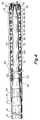
- FIG. 1shows a first embodiment of the invention.
- the guidewirewhen intended for percutaneous transluminal coronary angioplasty may be approximately 175 cm to 300 cm in total length and includes an elongated rotationally rigid, longitudinally flexible core wire 10, preferably made of stainless steel or other material suitable for use as a guidewire shaft.
- the majority of the length(approximately 148 cm to 273 cm) is in the proximal segment 11 of the core wire which has a substantially uniform diameter of approximately 0.25 to 0.457 mm (0.010 to 0.018 inches).
- the proximal segment 11merges into a first tapered segment 12, about 3 cm long which, in turn, merges into an intermediate barrel segment 14, approximately 22.5 cm long and about 6 mils in diameter.
- Intermediate segment 14merges into a second tapered segment 15, about 3 cm long which, in turn, merges into a distal barrel segment 16, about 2.5 cm long and approximately .05 mm (2 mils) in diameter.
- the distal segment 16is more flexible than the intermediate segment 14.
- the core wirefrom taper 12 to distal segment 16 may have a continuous taper along its length.
- a distal coil 18, approximately 3 cm in length,is supported about the distal segment of the core wire and preferably is attached at its proximal end to the core wire by adhesive at joint 20.
- Suitable adhesivesinclude an ultraviolet curable adhesive or a cyanoacrylate adhesive.
- the joint 20alternatively may be welded, soldered or brazed.
- the distal coil 18is attached at its distal end to the core wire by a distal hemispherical tip weld 22.
- the distal coilmay be formed from a highly radiopaque material such as a gold/platinum or platinum/tungsten alloy.
- the diameter of the wire from which the distal coil 18 is woundpreferably is within the range of 0.025-0.102mm (.001-.004 inches).
- the outer diameter of the distal coil 18preferably is within the range of 0.25 - 0.46 mm (.010-.018 inches).
- a proximal coil 24is supported about the intermediate segment 14 of the core wire and is preferably attached at its distal end to the core wire by adhesive at joint 26.
- the proximal end of coil 24extends to the proximal end of the intermediate segment 14 of the core wire where it may be attached to the core wire by adhesive at joint 25.
- Joints 25 and 26may alternatively be welded, soldered or brazed.
- the outer diameter of the proximal coilis preferably the same as that of the distal coil 18.
- the proximal coilpreferably is 7-22 cm in length.
- the proximal coil 24may be less radiopaque than the distal coil 18 or of equivalent radiopacity.
- the proximal coilpreferably is formed from the same material as the distal coil but may be formed from smaller diameter wire to achieve the desired reduced radiopacity.
- the region of the guidewire between the proximal and distal coils, including a portion of the intermediate segment 14 and tapered segment 15,is covered by a flexible polymeric sleeve 34.
- the sleevepreferably having an outer diameter equal to that of the proximal and distal coils, provides a uniform outer diameter to the distal region of the guidewire such that the catheter will smoothly move over the guidewire during advancement.
- the sleevepreferably is flexible, kink resistant and includes a lubricious surface for aiding in guidewire maneuverability.
- the sleevepreferably is formed from a polymer material (such as polyamide or polyethylene) which exhibits the above properties. A hydrophilic or hydrophobic coating may be used to coat the outer surface of the polymer sleeve for added lubricity.
- the sleevepreferably is as thin as is practical, depending on the polymer material from which the sleeve is made, in order that the region of the sleeve displays a desired degree of flexibility.
- the wall thickness of the sleevepreferably falls within the range of 0.005 - 0.05 mm (.0002-.002 inches).
- the sleevepreferably covers the proximal end of the distal coil and the distal end of the proximal coil and may be 5-20 cm in length. As shown in FIG.
- the distal end of the proximal coil 24 and the proximal end of the distal coil 18can be stretched and tapered down to a smaller diameter in the region where they are attached to the core wire and overlapped by the ends of the polymer sleeve 34.
- the polymer sleevepreferably is adhesively attached at both ends to the guidewire. If adhesively attached, a small gap 23 exists between the inner surface of the sleeve and outer surfaces of the marker bands 28, 30 and 32 (discussed below). The size of the gap is approximately equal to 0.025mm (.001 inches) but would depend on the thickness of the sleeve wall and the outer diameter of the marker bands. The gap prevents the outer contour of the marker bands from projecting through the polymer sleeve. Alternatively, the sleeve may be heat shrunk about the guidewire.
- Radiopaque marker bands 28, 30 and 32are attached to the core wire between the proximal and distal coils.
- Marker bands 28, 30 and 32preferably are attached by adhesive at joints 36, 38 and 40, respectively. Alternatively, joints 36, 38 and 40 may be welded or brazed.
- the marker bandspreferably are made from a radiopaque material such as tantalum, platinum, gold or alloys thereof.
- the marker bandswill be spaced to provide optimum usability for various in vivo dimension measurements by a physician. Particularly, the spacing and dimensions of the marker bands provide reference lengths such that the length and shape of a lesion and adjacent arterial dimensions can be determined fluoroscopically. Such a determination can aid a physician in the selection of an appropriately sized balloon.
- the marker bandsalso provide reference locations which can aid in placing a post-stent balloon after stent placement. While the guidewire preferably includes three marker bands, as shown and described, it is envisioned that as few as one marker band could be used.
- the guidewire of the first embodimentthus has a distal tip section 16 that is highly radiopaque, an intermediate section (between the coils) that is non-radiopaque (except for the marker bands), and a proximal section that is moderately or highly radiopaque.
- a distal tip section 16that is highly radiopaque
- an intermediate sectionbetween the coils
- non-radiopaqueexcept for the marker bands
- a proximal sectionthat is moderately or highly radiopaque.
- Such an arrangementmay be referred to as "grey/white/black” or “black/white/black” (from the proximal to the distal ends), referring to its relative appearance under fluoroscopy.
- the highly radiopaque distal segmentprovides clear, visible, fluoroscopic indication of the distal tip of the guidewire to indicate clearly the guidewire position.
- the distal tip of the guidewireis advanced through and beyond the stenosis to be treated.
- the intermediate, non-radiopaque segmentis intended to be disposed at the region of the stenosis so that the region will be unobstructed by radiopaque effects of the guidewire.
- the full radiopaque effect of the radiopaque contrast liquid injected into the arterycan be visualized on the fluoroscope, particularly in the critical stenosed region of the artery.
- the moderately or highly radiopaque proximal segmentprovides an indication of the position and configuration of the more proximally located portions of the guidewire and, therefore, the proximal arterial anatomy.
- the "grey/white/black” or “black/white/black” configurationcan be achieved with the appropriate relative degrees of radiopacity by varying the thicknesses of the wires from which the coils are wound, as described above.
- the coilsmay be plated with varying thicknesses of radiopaque material to achieve the desired levels of radiopacity. The plating process is described in U.S. Patent No. 5, 144, 959 (Gambale).
- FIG. 2illustrates a second embodiment of guidewire which is fairly similar in construction to the first embodiment, but not in accordance with the present invention as herein claimed. Like elements in FIG. 2 are referred to by identical reference characters (to those in FIG. 1).
- the construction of the core wire 10, the distal coil 18, and the marker bands 28, 30 and 32is identical to that of the first embodiment (shown in FIG. 1).
- the guidewire of the second embodimentomits the proximal coil 24 of the first embodiment.
- a polymeric sleeve 34having the same properties as those described above, encases the proximal end of the distal coil and the marker bands.
- sleeve 34extends proximally of the marker bands to tapered segment 12 of core wire 10.
- the sleeveprovides a uniform outer diameter to the distal region of the guidewire to aid in smooth advancement of the catheter over the guidewire.
- the sleevepreferably is adhesively attached at both ends to the guidewire.
- a small gap 39exists between the inner surface of the sleeve and the outer surface of the marker bands 28, 30 and 32. The gap prevents the outer contour of the marker bands from projecting through the polymer sleeve.
- the sleevemay be heat shrunk about the guidewire such that, proximally of the marker bands, the sleeve 34 tapers down to fit tightly around the intermediate segment 14 of core wire to create a smooth transition.
- the guidewire of the second embodimentthus has a distal region including a distal tip section 16 that is highly radiopaque and a proximal section that is non-radiopaque.
- a distal tip section 16that is highly radiopaque
- a proximal sectionthat is non-radiopaque.
- white/blackfrom the proximal to the distal ends
- the highly radiopaque distal segmentprovides clear, visible fluoroscopic indication of the distal tip of the guidewire to indicate clearly the guidewire position and the proximal, non-radiopaque segment provides for unobstructed visualization of the stenosis.
- FIG. 3shows a third embodiment of guidewire in which a radiopaque coil 50 is supported by and attached to a distal region of the core wire 51.
- Core wire 51is an alternate embodiment core wire in which the distal barrel segment 16 of the core wire 10 of the first embodiment is absent and is replaced by a pair of round forming wires 53 and 55 which extend from tapered segment 15 to hemispherical tip weld 22.
- the forming wirestypically 3-7 cm in length, preferably are adhesively attached to tapered segment 15 and extend approximately 2 cm beyond the distal tip of core wire 51.
- the forming wirespreferably are formed from materials such as stainless steel, Sandvik 1RK91, PH455 or MP35N. Coil 50 can be used, however, with the core wire 10 of the first embodiment.
- the guidewire constructions of the first and second embodimentscan be used with the core wire 51.
- the distal end of the coil 50is attached to the hemispherical tip weld and the coil extends proximally to the tapered section 12 of the core wire.
- the proximal end of the coil 50is attached to the core wire by adhesive at joint 52.
- joint 52may be soldered or brazed.
- Coil 50may also be attached to the core wire, preferably by adhesive, near the distal end of the coil to add structural integrity to the distal end of the guidewire such that unwinding of the coil during advancement of the guidewire through an artery is prevented.
- Spring 50preferably is formed from a radiopaque material such as a platinum/gold or other suitable alloy.
- the diameter of the wire from which the coil 50 is woundpreferably is within the range of 0.025 - 0.10 mm (0.001-0.004 inches).
- the outer diameter of the coilpreferably is within the range of 0.25 - 0.46 mm (.010- .018 inches).
- a typical coil lengthfalls within the range of 5-20 cm. If using a coil having a length of 5 cm, the corresponding dimensions of the core wire would be less than that disclosed above, as will be appreciated by those skilled in the art.
- Spring 50has varying pitch along its length including multiple tightly wound coil sections separated by loosely wound coil sections.
- the tightly wound coil sectionsappear dark under fluoroscopy and the loosely wound coil sections appear light.
- the tightly wound coil sectionsare a distal section 54, preferably within the range of 2-3 cm in length, and a proximal section 55, within the range of 3-10 cm in length.
- the proximal and distal sectionsare highly radiopaque.
- An intermediate section 57 of the coilmay include multiple tightly wound coil sections 56, 58, 60, 62, and 64, and loosely wound coil sections 65, 66, 68, 70, 72, and 74.
- the intermediate section as a wholeappears light under fluoroscopy with the tightly wound sections appearing as dark markers, providing reference lengths and location markers for the physician.
- Markers 56, 58, 60 and 62may be uniformly spaced, preferably in 1 cm to 2 cm multiples. The number of markers and the length and spacing thereof, however, can be changed to suit a particular application. It is envisioned, that as few as one marker band could be used.
- Sleeve 34exhibits the same qualities as the sleeve described above in connection with the first and second embodiments.
- the sleeveprovides a uniform outer diameter to the distal region of the guidewire. The sleeve, therefore, helps to ensure smooth catheter movement over the guidewire during advancement.
- Sleeve 34preferably is adhesively attached to the guidewire at proximal 76 and distal 78 joints. If adhesively attached, a small gap 80 exists between the outer surface of spring 50 and the inner surface of sleeve 34.
- the gapenables free bending movement of the coils of spring 50 beneath the sleeve 34 while the guidewire is maneuvered through an artery. Additionally, the gap prevents the contour of the outer surface of the coils from projecting through the polymer sleeve 34.
- the ends of the sleeve 34maybe heat shrunk about the guidewire. It should be understood that the method of attaching the sleeve to the guidewire only at its ends by adhesive or by heat shrinking its ends can be used with any of the guidewire embodiments disclosed herein.
- the guidewire of the third embodimentthus has a distal tip section and a proximal section that are highly radiopaque and an intermediate section that is lightly radiopaque (except for the darker markers).
- Such an arrangementis referred to as "black/grey/black” (from the proximal to the distal ends), referring to its relative appearance under fluoroscopy.
- the highly radiopaque distal segmentprovides clear, visible fluoroscopic indication of the distal tip of the guidewire to indicate clearly the guidewire position and the intermediate.
- lightly radiopaque segmentprovides for substantially unobstructed visualization of the stenosis.
- the proximal and distal sections of the coilpreferably are equally highly radiopaque.
- the distal sectioncan be more radiopaque than the proximal section.
- the distal section 54 of the coilmay be wound from a wire having a greater diameter than that of the proximal section.
- the distal section 54may include another shorter radiopaque coil 90 which is supported by and attached to the extreme distal part of the core wire and which is located within the distal section of the coil, as shown in FIG. 4.
- inner coil 90is attached at its distal end to the hemispherical tip weld 22 and may be attached at its proximal end to the forming wires 53 and 55 and the tapered segment 15, preferably by adhesive. Alternatively, the proximal end of the inner coil may not be attached to any element.
- the embodiment of FIG. 4is identical to that of FIG. 3.
- the inner coil 90preferably has an outer diameter within the range of 0.15 - 0.30 mm(.006-.012 inches), a length within the range of 1-4 cm, and is made from a radiopaque material such as platinum, gold or a platinum/gold alloy.
- the diameter of the wire from which the inner coil is woundis preferably within the range of 0.025 - 0.076 mm (.001 to .003 inches).
- the inner coil 90is surrounded by the distal section of the coil 50 such that the distal section will appear highly radiopaque.
- FIG. 5shows a fourth embodiment of guidewire in which the guidewire preferably falls within the range of 180-300 cm in length and includes an elongated rotationally rigid, longitudinally flexible core wire 10, preferably made of stainless steel.
- the majority of the length (preferably 110-280 cm) of the core wireis in the proximal portion 11 which has a substantially uniform diameter, typically within the range of 0.25 - 0.46 mm (10-18 mils).
- the proximal portion 11merges into a first tapered segment 12, preferably 2-10 cm in length, which, in turn, merges into a first barrel segment 13, preferably 10-20 cm in length.
- the diameter of barrel segment 13preferably is within the range of 0.13 - 0.30 mm (5-12 mils), less than that of proximal portion 11.
- First barrel segment 13merges into a second tapered segment 17, preferably 2-6 cm in length, which, in turn, merges into a second barrel segment 19, preferably 5-25 cm in length.
- the diameter of barrel segment 19preferably is within the range of 0.10 - 0.25 mm(4-10 mils), less than that of first barrel segment 13.
- Barrel segment 19merges into a third tapered segment 21, preferably 2-10 cm in length, which extends to the distal end of the core wire.
- One or more forming wiresextend from tapered segment 21 to a rounded tip weld 22.
- the forming wirestypically one to five cm in length, preferably are adhesively attached to tapered segment 21 at joint 78 and extend approximately 2 cm beyond the distal tip of core wire 10.
- joint 78can be soldered or brazed.
- the forming wirespreferably are made from a specially treated precipitation hardenable alloy material.
- One such materialis an alloy of nickel, cobalt, molybdenum and chromium, commercially available from Fort Wayne Metals of Fort Wayne, Indiana under the trade designation MP35N.
- Another suitable materialis a single stage martensitic precipitation hardenable stainless steel having modified proportions of chromium and nickel and with additional elements of copper and titanium, commercially available from Carpenter Steel Co. of Reading, Pennsylvania under the trade designation 455PH.
- Still another suitable materialis a precipitation hardenable alloy that is commercially available from Sandvik Steel under the trade designation Sandvik 1RK91.
- distal region 27 of the core wirehas been shown and described herein as including two tapered segments, two barrel segments and two forming wires, it should be understood that other core wires can be used with this fourth embodiment such as, for example, a core wire that has a distal region including only a single barrel segment which merges into a tapered segment that extends to the distal end of the core wire (with or without forming wires).
- a core wire having a distal regionthat either includes one or more forming wires or, alternatively, a core wire that extends to the distal tip of the guidewire.
- a radiopaque coil 50is supported by and attached to the distal region 27 of the core wire 10.
- the distal end of the coil 50is attached by the hemispherical tip weld.
- the coilis attached to the core wire at joint 78.
- Joint 78also adds integrity to the structure of the distal end of the guidewire to prevent the coil 50 from separating from the core wire if the forming wires break during use.
- the coilextends proximally to the tapered section 12 of the core wire 10.
- the proximal end of the coilis attached to the core wire by adhesive at joint 52. Alternatively, joint 52 can be soldered or brazed.
- Spring 50preferably is formed from a radiopaque material such as platinum/gold or other suitable alloy.
- the diameter of the wire from which the coil is woundpreferably is within the range of 0.038 - 0.076 mm (.0015-.003 inches).
- the outer diameter of the coilpreferably is within the range of 0.25 - 0.45 mm (.010-.018 inches).
- a typical coil lengthfalls within the range of 15-40 cm. While the coil is shown in FIG. 5 as having an outer diameter that is less than that of the proximal portion 11 of the core wire, it is to be appreciated that the outer diameter of the coil is preferably equal to or approximately equal to the outer diameter of the proximal portion 11 of the core wire.
- Spring 50has varying pitch along its length including distal and proximal tightly wound coil sections 54 and 55 separated by an intermediate loosely wound window coil section 57.
- the tightly wound coil sectionsappear dark under fluoroscopy and the loosely wound window coil section appears light.
- Distal section 54preferably falls within the range of one to five cm in length
- proximal section 55preferably falls within the range of 10-25 cm in length
- intermediate window section 57preferably falls within the range of 5-20 cm in length.
- Intermediate window section 57includes a number of short tightly wound coil sections (not shown) separated by loosely wound coil sections as in the embodiment of FIG. 3.
- the tightly wound sectionsappear as dark markers under fluoroscopy for providing reference lengths and location marks for a physician.
- the number of markers and the length and spacing thereofcan be selected to suit a particular application.
- the sleeve 81is kink resistant and includes a lubricious surface for aiding in guidewire maneuverability.
- the sleevepreferably is formed from polyethylene terephthalate (PET) but may be formed from other thermoplastic polymers such as polyethelene.
- PETpolyethylene terephthalate
- a hydrophilic or hydrophobic coatingmay be used to coat the outer surface of the guidewire including the polymer sleeve for added lubricity.
- the sleevepreferably is as thin as is practical, depending on the polymer material from which the sleeve is made, in order that the region of the sleeve displays a desired degree of flexibility.
- the wall thickness of the sleevepreferably falls within the range of 0.005 - 0.05 mm (.0002-.002 inches).
- the sleeve 81is attached to the guidewire only at its proximal and distal ends 82 and 84 (each preferably within the range of 0.5-2 cm in length) by heat shrinking the sleeve only at those ends. Only the ends 82 and 84 of the sleeve 81 are respectively heat shrunk about the tightly wound coils of the proximal 55 and distal 54 regions immediately adjacent the window section 57.
- a small gap 80exists between the outer surface of the intermediate section 57 of coil 50 and the inner surface of sleeve 81.
- the size of the gapis approximately equal to .00025 mm (.0001 inches) but would depend on the thickness of the sleeve wall and the outer diameter of the spring.
- the gapprevents the contour of the outer surface of the coils from projecting through the sleeve and contacting the inner arterial wall (which would occur if the sleeve were heat shrunk about the entire length of the coil) so that the guidewire can be navigated smoothly through the artery during use.
- the sleeve 81insulates the loosely wound coils of the intermediate section 57 from the inner arterial wall to prevent them from significant movement relative to one another during advancement through an artery. Such movement could result in altering the fluoroscopic image of the guidewire and/or altering the structure and functionality of the coils of the spring.
- the distal region of the fourth embodiment (FIG. 5) of the guidewirethus has distal tip and proximal sections that are highly radiopaque and an intermediate section that is lightly radiopaque.
- Such an arrangementis referred to as "black/grey/black" (from the proximal section to the distal end), referring to its relative appearance under fluoroscopy.
- the highly radiopaque distal segmentprovides clear, visible fluoroscopic indication of the distal tip of the guidewire to indicate clearly the guidewire position.
- the distal tip of the guidewireis advanced through and beyond the stenosis to be treated.
- the intermediate, lightly radiopaque segmentis intended to be disposed at the region of the stenosis so that the region will not be materially obstructed by radiopaque effects of the guidewire.
- the radiopaque proximal segmentprovides an indication of the position and configuration of the more proximally located portions of the guidewire and, therefore, the proximal arterial anatomy, so that a physician can observe the more proximally located portions of the guidewire.
- the proximal and distal sections of the coilpreferably are equally highly radiopaque.
- the distal sectioncan be more radiopaque than the proximal section.
- the distal section 54 of the coilmay be plated with a radiopaque material.
- the guidewire of the present inventionprovides a number of advantages.
- the guidewirefacilitates better lesien assessment both by providing a non-obstructing region that does not impair fluoroscopic evaluation of the shape of the lesion and by providing a radiopaque proximal section that allows visualization of the proximal portion of the wire. It also provides radiopaque markers which offer a simple means by which the physician can determine the length of the lesion, adjacent arterial dimensions, and/or reference lesion or stent location. Selection of an appropriately, sized balloon and, if necessary, selection of an appropriate stent is, therefore, facilitated. Additionally, the sleeve provides a uniform outer diameter to the distal region of the guidewire to ensure smooth movement of the catheter during advancement.
- the outer contour of the coilsis prevented from projecting through the sleeve, and the sleeve insulates the loosely wound coils from the inner arterial wall, preventing them from substantial relative movement.
- a guidewire having varied degrees of radiopacitywhereby, a distal section of the distal region of the guidewire appears dark under fluoroscopy and an intermediate section of the distal region appears generally white (or light in an alternate embodiment). At least one radiopaque marker is located in the intermediate section for providing reference lengths and location marks for a physician.
- a polymer sleeveencases at least part of the distal region, providing a uniform outer diameter to the region (in some embodiments), to aid in smooth catheter advancement.
Landscapes
- Health & Medical Sciences (AREA)
- Life Sciences & Earth Sciences (AREA)
- Biophysics (AREA)
- Pulmonology (AREA)
- Engineering & Computer Science (AREA)
- Anesthesiology (AREA)
- Biomedical Technology (AREA)
- Heart & Thoracic Surgery (AREA)
- Hematology (AREA)
- Animal Behavior & Ethology (AREA)
- General Health & Medical Sciences (AREA)
- Public Health (AREA)
- Veterinary Medicine (AREA)
- Media Introduction/Drainage Providing Device (AREA)
- Materials For Medical Uses (AREA)
Description
Claims (15)
- A medical guidewire having an elongate flexible shaft (10); a distalradiopaque coil (18) supported about and attached to a distal portionof the shaft (15); a proximal radiopaque coil (24) supported about andattached to an intermediate portion (14) of the shaft, the proximal coilbeing spaced from the distal coil; a polymer sleeve (34) encasing theshaft between the proximal and distal coils and at least a portion ofthe proximal coil (24) characterized in that:at least one radiopaque marker (28, 30, 32) is attached to theshaft between the distal and proximal coils (18, 24), at east one markerbeing encased by the polymer sleeve; (34) andthe polymer sleeve (34) encases at least a portion of the distal coil(18).
- A medical guidewire as claimed in claim 1, further characterized inthat the polymer sleeve (34) encases a proximal region only of thedistal coil and a distal region only of the proximal coil (24).
- A medical guidewire as claimed in claim 1 or 2 further characterizedin that the at least one marker (28, 30, 32) comprises at least oneradiopaque marker band.
- A medical guidewire as claimed in any one of the preceding claimsfurther characterized in that the distal coil (18) is more radiopaquethan the proximal coil (24) such that the distal coil will appear darkerthan the proximal coil under fluoroscopy.
- A medical guidewire as claimed in claim 4 further characterized inthat the wire from which the distal coil (18) is wound has a greaterdiameter than the wire from which the proximal coil (24) is wound.
- A medical guidewire as claimed in any one of claims 1 to 3 furthercharacterized in that the radiopacity of the distal coil (18) isapproximately equal to the radiopacity of the proximal coil (24) suchthat both coils will appear equally dark under fluoroscopy.
- A medical guidewire as claimed in any one of the preceding claims,and further characterized in thata gap (23) exists between the at least one marker (28, 30, 32)and the polymer sleeve (34).
- A medical guidewire as claimed in any one of the preceding claims,and further characterized in that regions of the polymer sleeve (34)are attached to the guidewire adhesively.
- A medical guidewire as claimed in any one of claims 1 to 6, andfurther characterized in that the ends of the polymer sleeve (34) areheat shrunk about the guidewire.
- A medical guidewire as claimed in claim 9 further characterized inthat the polymer sleeve (81) is heat shrunk to the guidewire only atthe ends (82, 84) of the sleeve.
- A medical guidewire as claimed in any one of the preceding claimswherein the at least one marker comprises a plurality of marker bands(28, 30, 32) having predetermined spacing.
- A medical guidewire as claimed in claim 11, wherein the plurality ofmarker bands (28, 30, 32) has equal spacing.
- A medical guidewire as claimed in any one of the preceding claimswherein the polymer sleeve also encases the proximal end of theproximal coil (24).
- A medical guidewire comprising:a first radiopaque coil (50) supported by and attached to a distalregion of a shaft (51),characterized in thatthe first coil has highly radiopaque distal(54) and proximal (55) sections and a more moderately radiopaqueintermediate section (57), the intermediate section of the first coilincludes at least one tightly wound coil section (56, 58, 60, 62, 64)separated from the distal and proximal coil sections by loosely wound coilsections (65, 66, 68, 70, 72, 74); said distal coil section constituting adistal radiopaque coil (18), said proximal coil section constituting aproximal radiopaque coil (24) and saidat least one tightly wound coil section of saidintermediate coil section defininga radiopaque marker (28, 30, 32), and a polymer sleeve (34, 81)encases the intermediate coil section (57) of thefirst coil (50) and at least portions of the proximal and distal coil sections (54, 55).
- A medical guidewire as claimed in claim 14 further including asecond radiopaque coil (90) supported by the distal region of theshaft, wherein the distal section (54) of the first coil (50) surrounds the secondcoil (90).
Applications Claiming Priority (5)
| Application Number | Priority Date | Filing Date | Title |
|---|---|---|---|
| US21255894A | 1994-03-11 | 1994-03-11 | |
| US212558 | 1994-03-11 | ||
| US383322 | 1995-02-03 | ||
| US08/383,322US5606981A (en) | 1994-03-11 | 1995-02-03 | Catheter guidewire with radiopaque markers |
| PCT/US1995/003076WO1995024237A2 (en) | 1994-03-11 | 1995-03-09 | Catheter guidewire with radiopaque markers |
Publications (3)
| Publication Number | Publication Date |
|---|---|
| EP0749334A1 EP0749334A1 (en) | 1996-12-27 |
| EP0749334B1true EP0749334B1 (en) | 2000-06-14 |
| EP0749334B2 EP0749334B2 (en) | 2004-08-25 |
Family
ID=26907255
Family Applications (1)
| Application Number | Title | Priority Date | Filing Date |
|---|---|---|---|
| EP95914010AExpired - LifetimeEP0749334B2 (en) | 1994-03-11 | 1995-03-09 | Catheter guidewire with radiopaque markers |
Country Status (6)
| Country | Link |
|---|---|
| US (1) | US5606981A (en) |
| EP (1) | EP0749334B2 (en) |
| JP (1) | JPH09510125A (en) |
| CA (1) | CA2184484A1 (en) |
| DE (1) | DE69517518T3 (en) |
| WO (1) | WO1995024237A2 (en) |
Cited By (3)
| Publication number | Priority date | Publication date | Assignee | Title |
|---|---|---|---|---|
| DE102004023642A1 (en)* | 2004-05-10 | 2005-12-08 | Restate Patent Ag | Catheter guidewire, especially for percutaneous transluminal coronary angioplasty |
| US7033325B1 (en) | 1989-12-19 | 2006-04-25 | Scimed Life Systems, Inc. | Guidewire with multiple radiopaque marker sections |
| US10111987B2 (en) | 2011-03-14 | 2018-10-30 | Innovatech, Llc | Marked fluoropolymer surfaces and method of manufacturing same |
Families Citing this family (136)
| Publication number | Priority date | Publication date | Assignee | Title |
|---|---|---|---|---|
| ATE140159T1 (en)* | 1993-05-19 | 1996-07-15 | Schneider Europ Ag | GUIDE WIRE |
| US6673025B1 (en) | 1993-12-01 | 2004-01-06 | Advanced Cardiovascular Systems, Inc. | Polymer coated guidewire |
| US6245068B1 (en) | 1994-08-08 | 2001-06-12 | Scimed Life Systems, Inc. | Resilient radiopaque electrophysiology electrodes and probes including the same |
| DE69517501T2 (en)* | 1995-03-02 | 2001-03-08 | Schneider (Europe) Gmbh, Buelach | Method of making a guidewire |
| US5916178A (en)* | 1995-03-30 | 1999-06-29 | Medtronic, Inc. | Steerable high support guidewire with thin wall nitinol tube |
| US5662622A (en)* | 1995-04-04 | 1997-09-02 | Cordis Corporation | Intravascular catheter |
| US5836892A (en)* | 1995-10-30 | 1998-11-17 | Cordis Corporation | Guidewire with radiopaque markers |
| US5924998A (en)* | 1997-03-06 | 1999-07-20 | Scimed Life System, Inc. | Guide wire with hydrophilically coated tip |
| US6251086B1 (en)* | 1999-07-27 | 2001-06-26 | Scimed Life Systems, Inc. | Guide wire with hydrophilically coated tip |
| US7455646B2 (en) | 1997-06-04 | 2008-11-25 | Advanced Cardiovascular Systems, Inc. | Polymer coated guide wire |
| US7494474B2 (en)* | 1997-06-04 | 2009-02-24 | Advanced Cardiovascular Systems, Inc. | Polymer coated guidewire |
| US5919126A (en)* | 1997-07-07 | 1999-07-06 | Implant Sciences Corporation | Coronary stent with a radioactive, radiopaque coating |
| US6010445A (en)* | 1997-09-11 | 2000-01-04 | Implant Sciences Corporation | Radioactive medical device and process |
| US6132388A (en) | 1997-10-16 | 2000-10-17 | Scimed Life Systems, Inc. | Guide wire tip |
| US6175760B1 (en) | 1998-02-17 | 2001-01-16 | University Of Iowa Research Foundation | Lesion localizer for nuclear medicine |
| US6059767A (en)* | 1998-02-25 | 2000-05-09 | Norborn Medical, Inc. | Steerable unitary infusion catheter/guide wire incorporating detachable infusion port assembly |
| US6746422B1 (en) | 2000-08-23 | 2004-06-08 | Norborn Medical, Inc. | Steerable support system with external ribs/slots that taper |
| US20060074442A1 (en)* | 2000-04-06 | 2006-04-06 | Revascular Therapeutics, Inc. | Guidewire for crossing occlusions or stenoses |
| US9254143B2 (en)* | 1998-02-25 | 2016-02-09 | Revascular Therapeutics, Inc. | Guidewire for crossing occlusions or stenoses having a shapeable distal end |
| US6824550B1 (en)* | 2000-04-06 | 2004-11-30 | Norbon Medical, Inc. | Guidewire for crossing occlusions or stenosis |
| US20080140101A1 (en)* | 2006-12-07 | 2008-06-12 | Revascular Therapeutic, Inc. | Apparatus for crossing occlusions or stenoses |
| US20070225615A1 (en)* | 2006-03-22 | 2007-09-27 | Revascular Therapeutics Inc. | Guidewire controller system |
| EP0947221A3 (en)* | 1998-03-31 | 2000-04-26 | Terumo Kabushiki Kaisha | Laser irradiation device |
| US6139511A (en)* | 1998-06-29 | 2000-10-31 | Advanced Cardiovascular Systems, Inc. | Guidewire with variable coil configuration |
| WO2001024683A2 (en)* | 1999-10-04 | 2001-04-12 | Novoste Corporation | Interventional injury sizing tool for radiation therapy |
| AU1013001A (en) | 1999-10-26 | 2001-05-08 | Cedara Software Corp. | Catheter with radiopaque markers for 3d position tracking |
| WO2001036034A2 (en)* | 1999-11-16 | 2001-05-25 | Advanced Cardiovascular Systems, Inc. | Polymer coated guidewire |
| US6520934B1 (en) | 1999-12-29 | 2003-02-18 | Advanced Cardiovascular Systems, Inc. | Catheter assemblies with flexible radiopaque marker |
| US7381198B2 (en) | 2000-08-23 | 2008-06-03 | Revascular Therapeutics, Inc. | Steerable distal support system |
| EP3006057A1 (en) | 2000-08-24 | 2016-04-13 | Cordis Corporation | Fluid delivery systems for delivering fluids to multi-lumen catheters |
| US6620114B2 (en)* | 2000-10-05 | 2003-09-16 | Scimed Life Systems, Inc. | Guidewire having a marker segment for length assessment |
| JP4680372B2 (en)* | 2000-11-15 | 2011-05-11 | 川澄化学工業株式会社 | Guide wire |
| US6497646B1 (en)* | 2001-03-14 | 2002-12-24 | Cordis Corporation | Intravascular radiotherapy source ribbon having variable radiopacity |
| US6636758B2 (en) | 2001-05-01 | 2003-10-21 | Concentric Medical, Inc. | Marker wire and process for using it |
| US6575920B2 (en) | 2001-05-30 | 2003-06-10 | Scimed Life Systems, Inc. | Distal tip portion for a guide wire |
| US6638245B2 (en)* | 2001-06-26 | 2003-10-28 | Concentric Medical, Inc. | Balloon catheter |
| US6702782B2 (en) | 2001-06-26 | 2004-03-09 | Concentric Medical, Inc. | Large lumen balloon catheter |
| US6612998B2 (en)* | 2001-11-28 | 2003-09-02 | Advanced Cardiovascular Systems, Inc. | Guide wire with marker sleeve |
| US20050228479A1 (en)* | 2001-11-29 | 2005-10-13 | Cook Incorporated | Medical device delivery system |
| US6832715B2 (en) | 2001-12-03 | 2004-12-21 | Scimed Life Systems, Inc. | Guidewire distal tip soldering method |
| JP4028245B2 (en)* | 2002-01-28 | 2007-12-26 | テルモ株式会社 | Guide wire |
| US7022086B2 (en) | 2002-05-21 | 2006-04-04 | Scimed Life Systems, Inc. | Guidewire with encapsulated marker |
| US7153277B2 (en)* | 2002-12-03 | 2006-12-26 | Scimed Life Systems, Inc. | Composite medical device with markers |
| WO2004049970A2 (en)* | 2002-12-04 | 2004-06-17 | Lake Region Manufacturing, Inc. | Marked guidewires |
| US20040133129A1 (en)* | 2003-01-03 | 2004-07-08 | Mindguard Ltd. | Measurements in a body lumen using guidewire with spaced markers |
| US7582740B2 (en)* | 2003-04-17 | 2009-09-01 | The Trustees Of Columbia University In The City Of New York | Methods and kits for detecting SARS-associated coronavirus |
| US8337519B2 (en) | 2003-07-10 | 2012-12-25 | Boston Scientific Scimed, Inc. | Embolic protection filtering device |
| JP4677205B2 (en)* | 2003-07-17 | 2011-04-27 | テルモ株式会社 | Guide wire |
| US7833175B2 (en)* | 2003-09-05 | 2010-11-16 | Boston Scientific Scimed, Inc. | Medical device coil |
| US20050054952A1 (en)* | 2003-09-05 | 2005-03-10 | Scimed Life Systems, Inc. | Elongated medical device for intracorporal use |
| US7540845B2 (en)* | 2003-09-05 | 2009-06-02 | Boston Scientific Scimed, Inc | Medical device coil |
| US20050131316A1 (en)* | 2003-12-15 | 2005-06-16 | Cook Incorporated | Guidewire with flexible tip |
| US7641647B2 (en)* | 2003-12-29 | 2010-01-05 | Boston Scientific Scimed, Inc. | Medical device with modified marker band |
| EP2286863A3 (en) | 2004-01-09 | 2011-03-23 | Corazon Technologies, Inc. | Multilumen catheters and methods for their use |
| JP3626488B1 (en)* | 2004-03-15 | 2005-03-09 | 朝日インテック株式会社 | Medical guidewire |
| US7844344B2 (en) | 2004-03-30 | 2010-11-30 | Medtronic, Inc. | MRI-safe implantable lead |
| JP3694312B1 (en)* | 2005-01-26 | 2005-09-14 | 朝日インテック株式会社 | Medical guidewire |
| US8784336B2 (en) | 2005-08-24 | 2014-07-22 | C. R. Bard, Inc. | Stylet apparatuses and methods of manufacture |
| DE102005050344A1 (en)* | 2005-10-20 | 2007-05-03 | Siemens Ag | Cryocatheter for medical investigation and treatment equipment for e.g. diagnosis and treatment of heart infarcts, has image capture device that maps region of vessel around balloon arranged near catheter tip |
| US20080114435A1 (en)* | 2006-03-07 | 2008-05-15 | Med Institute, Inc. | Flexible delivery system |
| US7674253B2 (en)* | 2006-08-18 | 2010-03-09 | Kensey Nash Corporation | Catheter for conducting a procedure within a lumen, duct or organ of a living being |
| US20080108974A1 (en)* | 2006-10-20 | 2008-05-08 | Vital Signs, Inc. | Reinforced catheter with radiopaque distal tip and process of manufacture |
| US7881806B2 (en)* | 2006-10-31 | 2011-02-01 | Medtronic, Inc. | Medical lead delivery device |
| US9044593B2 (en) | 2007-02-14 | 2015-06-02 | Medtronic, Inc. | Discontinuous conductive filler polymer-matrix composites for electromagnetic shielding |
| US8308658B2 (en) | 2007-04-13 | 2012-11-13 | Neometrics, Inc. | Medical guidewire |
| US8483842B2 (en) | 2007-04-25 | 2013-07-09 | Medtronic, Inc. | Lead or lead extension having a conductive body and conductive body contact |
| JP5513394B2 (en)* | 2007-10-11 | 2014-06-04 | ギヴン イメージング(ロサンジェルス)エルエルシー | System for measuring and displaying the location of radiologically contrasted material inside a luminal organ |
| US8500697B2 (en)* | 2007-10-19 | 2013-08-06 | Pressure Products Medical Supplies, Inc. | Transseptal guidewire |
| CA2845188A1 (en)* | 2007-10-29 | 2009-05-07 | Schwager Medica Ag | Catheter |
| US7806837B2 (en)* | 2007-11-07 | 2010-10-05 | William Cook Europe Aps | Guide wire for catheter |
| ES2465915T3 (en) | 2007-11-26 | 2014-06-09 | C.R. Bard, Inc. | Integrated system for intravascular catheter placement |
| US8781555B2 (en) | 2007-11-26 | 2014-07-15 | C. R. Bard, Inc. | System for placement of a catheter including a signal-generating stylet |
| US10751509B2 (en) | 2007-11-26 | 2020-08-25 | C. R. Bard, Inc. | Iconic representations for guidance of an indwelling medical device |
| US9521961B2 (en) | 2007-11-26 | 2016-12-20 | C. R. Bard, Inc. | Systems and methods for guiding a medical instrument |
| US9649048B2 (en) | 2007-11-26 | 2017-05-16 | C. R. Bard, Inc. | Systems and methods for breaching a sterile field for intravascular placement of a catheter |
| US8048471B2 (en)* | 2007-12-21 | 2011-11-01 | Innovatech, Llc | Marked precoated medical device and method of manufacturing same |
| US7811623B2 (en)* | 2007-12-21 | 2010-10-12 | Innovatech, Llc | Marked precoated medical device and method of manufacturing same |
| US7714217B2 (en) | 2007-12-21 | 2010-05-11 | Innovatech, Llc | Marked precoated strings and method of manufacturing same |
| US8231927B2 (en) | 2007-12-21 | 2012-07-31 | Innovatech, Llc | Marked precoated medical device and method of manufacturing same |
| US8231926B2 (en) | 2007-12-21 | 2012-07-31 | Innovatech, Llc | Marked precoated medical device and method of manufacturing same |
| ATE469668T1 (en)* | 2007-12-28 | 2010-06-15 | Terumo Corp | GUIDE WIRE |
| JP5430065B2 (en)* | 2007-12-28 | 2014-02-26 | テルモ株式会社 | Guide wire |
| JP5354916B2 (en)* | 2008-01-25 | 2013-11-27 | テルモ株式会社 | Transendoscopic guidewire |
| US9037263B2 (en) | 2008-03-12 | 2015-05-19 | Medtronic, Inc. | System and method for implantable medical device lead shielding |
| US9901714B2 (en)* | 2008-08-22 | 2018-02-27 | C. R. Bard, Inc. | Catheter assembly including ECG sensor and magnetic assemblies |
| IT1391568B1 (en)* | 2008-09-05 | 2012-01-11 | E V R Endovascular Res Es S A | CABLE GUIDE TO NAVIGATION THROUGH AN ANATOMY WITH BRANCHED DUCTS |
| US8657821B2 (en) | 2008-11-14 | 2014-02-25 | Revascular Therapeutics Inc. | Method and system for reversibly controlled drilling of luminal occlusions |
| US8162891B2 (en)* | 2008-11-26 | 2012-04-24 | Revascular Therapeutics, Inc. | Delivery and exchange catheter for storing guidewire |
| US12220538B2 (en) | 2008-12-08 | 2025-02-11 | Scientia Vascular, Inc. | Micro-fabricated intravascular devices having varying diameters |
| EP2410926A4 (en)* | 2009-03-25 | 2012-12-05 | Svelte Medical Systems Inc | BALLOON EQUIPMENT AND METHOD FOR THE PRODUCTION AND USE THEREOF |
| US10035014B2 (en)* | 2009-04-30 | 2018-07-31 | Medtronic, Inc. | Steering an implantable medical lead via a rotational coupling to a stylet |
| US9532724B2 (en) | 2009-06-12 | 2017-01-03 | Bard Access Systems, Inc. | Apparatus and method for catheter navigation using endovascular energy mapping |
| WO2011097312A1 (en) | 2010-02-02 | 2011-08-11 | C.R. Bard, Inc. | Apparatus and method for catheter navigation and tip location |
| EP2912999B1 (en) | 2010-05-28 | 2022-06-29 | C. R. Bard, Inc. | Apparatus for use with needle insertion guidance system |
| JP5392784B2 (en)* | 2010-06-17 | 2014-01-22 | 朝日インテック株式会社 | Medical guidewire |
| JP5736735B2 (en)* | 2010-11-09 | 2015-06-17 | 住友ベークライト株式会社 | catheter |
| JP5743267B2 (en)* | 2011-06-30 | 2015-07-01 | 朝日インテック株式会社 | Guide wire |
| US10029076B2 (en) | 2012-02-28 | 2018-07-24 | Covidien Lp | Intravascular guidewire |
| US9463317B2 (en) | 2012-04-19 | 2016-10-11 | Medtronic, Inc. | Paired medical lead bodies with braided conductive shields having different physical parameter values |
| WO2014031854A1 (en)* | 2012-08-23 | 2014-02-27 | Volcano Corporation | Device, system, and method utilizing a radiopaque element for anatomical lesion length estimation |
| US9504476B2 (en)* | 2012-10-01 | 2016-11-29 | Microvention, Inc. | Catheter markers |
| JP2014213126A (en)* | 2013-04-30 | 2014-11-17 | 朝日インテック株式会社 | Guide wire |
| US9993638B2 (en) | 2013-12-14 | 2018-06-12 | Medtronic, Inc. | Devices, systems and methods to reduce coupling of a shield and a conductor within an implantable medical lead |
| WO2015120256A2 (en) | 2014-02-06 | 2015-08-13 | C.R. Bard, Inc. | Systems and methods for guidance and placement of an intravascular device |
| JP6294211B2 (en)* | 2014-02-24 | 2018-03-14 | 朝日インテック株式会社 | Guide wire |
| DE202014100863U1 (en)* | 2014-02-26 | 2014-03-14 | Cormedics Medizintechnik GmbH | Guidewire for medical devices |
| WO2015141290A1 (en)* | 2014-03-19 | 2015-09-24 | テルモ株式会社 | Guide wire |
| EP3145414B1 (en) | 2014-05-20 | 2021-10-13 | Koninklijke Philips N.V. | Intravascular devices having drive cables with radiopaque markers |
| JP6476614B2 (en)* | 2014-07-03 | 2019-03-06 | 住友ベークライト株式会社 | Medical equipment |
| EP3171931B1 (en) | 2014-07-23 | 2021-11-10 | Medtronic, Inc. | Methods of shielding implantable medical leads and implantable medical lead extensions |
| EP3191175B1 (en) | 2014-07-24 | 2022-03-02 | Medtronic, Inc. | Apparatus for shielding implantable medical leads and lead extensions |
| US11090465B2 (en)* | 2014-08-21 | 2021-08-17 | Boston Scientific Scimed, Inc. | Medical device with support member |
| US10973584B2 (en) | 2015-01-19 | 2021-04-13 | Bard Access Systems, Inc. | Device and method for vascular access |
| JP5967255B2 (en)* | 2015-04-15 | 2016-08-10 | 住友ベークライト株式会社 | Catheter and method for manufacturing catheter |
| JP5948535B1 (en)* | 2015-05-29 | 2016-07-06 | 株式会社エフエムディ | Medical guidewire |
| WO2016210325A1 (en) | 2015-06-26 | 2016-12-29 | C.R. Bard, Inc. | Connector interface for ecg-based catheter positioning system |
| US20170072165A1 (en)* | 2015-09-11 | 2017-03-16 | Cathera, Inc. | Catheter shaft and associated devices, systems, and methods |
| US11000207B2 (en) | 2016-01-29 | 2021-05-11 | C. R. Bard, Inc. | Multiple coil system for tracking a medical device |
| CN113996519B (en)* | 2016-04-25 | 2023-03-21 | 莱斯桑百特医疗解决方案股份有限公司 | Mechanical waveguide with marker |
| US11052228B2 (en) | 2016-07-18 | 2021-07-06 | Scientia Vascular, Llc | Guidewire devices having shapeable tips and bypass cuts |
| US11207502B2 (en) | 2016-07-18 | 2021-12-28 | Scientia Vascular, Llc | Guidewire devices having shapeable tips and bypass cuts |
| ES2966345T3 (en) | 2017-05-26 | 2024-04-22 | Scientia Vascular Inc | Microfabricated medical device with a non-helical cutting arrangement |
| EP4059557A3 (en)* | 2017-09-30 | 2022-09-28 | Asahi Intecc Co., Ltd. | Guide wire |
| US11305095B2 (en) | 2018-02-22 | 2022-04-19 | Scientia Vascular, Llc | Microfabricated catheter having an intermediate preferred bending section |
| US10953195B2 (en) | 2018-06-01 | 2021-03-23 | Covidien Lp | Flexible tip catheter |
| CN108926763A (en)* | 2018-07-28 | 2018-12-04 | 上海上医康鸽医用器材有限责任公司 | Microtubular, push component, Embolism for fallopian tube, dredging, contrast apparatus and application method |
| US10992079B2 (en) | 2018-10-16 | 2021-04-27 | Bard Access Systems, Inc. | Safety-equipped connection systems and methods thereof for establishing electrical connections |
| JP6631682B2 (en)* | 2018-11-20 | 2020-01-15 | 住友ベークライト株式会社 | Medical equipment |
| US11452533B2 (en) | 2019-01-10 | 2022-09-27 | Abbott Cardiovascular Systems Inc. | Guide wire tip having roughened surface |
| US12178975B2 (en)* | 2020-01-23 | 2024-12-31 | Scientia Vascular, Inc. | Guidewire having enlarged, micro-fabricated distal section |
| US12343485B2 (en) | 2020-01-23 | 2025-07-01 | Scientia Vascular, Inc. | High torque guidewire device |
| CN115916316A (en)* | 2020-07-03 | 2023-04-04 | 朝日英达科株式会社 | guide wire |
| US20220105314A1 (en) | 2020-10-01 | 2022-04-07 | Teleflex Medical Incorporated | Stylet with improved threadability |
| US12296112B2 (en) | 2020-10-05 | 2025-05-13 | Scientia Vascular, Inc. | Microfabricated catheter devices with high axial strength |
| CN114831696A (en)* | 2022-05-06 | 2022-08-02 | 上海励楷科技有限公司 | Conveying structure and have its catch and tie conveyor |
| WO2025062987A1 (en)* | 2023-09-21 | 2025-03-27 | テルモ株式会社 | Guide wire |
Family Cites Families (46)
| Publication number | Priority date | Publication date | Assignee | Title |
|---|---|---|---|---|
| US3757768A (en)* | 1972-04-07 | 1973-09-11 | Medical Evaluation Devices And | Manipulable spring guide-catheter and tube for intravenous feeding |
| US4279252A (en)* | 1979-08-24 | 1981-07-21 | Martin Michael T | X-ray scaling catheter |
| US4545390A (en)* | 1982-09-22 | 1985-10-08 | C. R. Bard, Inc. | Steerable guide wire for balloon dilatation procedure |
| US4456017A (en)* | 1982-11-22 | 1984-06-26 | Cordis Corporation | Coil spring guide with deflectable tip |
| USRE33911E (en)* | 1983-07-13 | 1992-05-05 | Advanced Cardiovascular Systems, Inc. | Catheter guide wire with short spring tip and method of using the same |
| US4538622A (en)* | 1983-11-10 | 1985-09-03 | Advanced Cardiovascular Systems, Inc. | Guide wire for catheters |
| US4619274A (en)* | 1985-04-18 | 1986-10-28 | Advanced Cardiovascular Systems, Inc. | Torsional guide wire with attenuated diameter |
| US4721117A (en)* | 1986-04-25 | 1988-01-26 | Advanced Cardiovascular Systems, Inc. | Torsionally stabilized guide wire with outer jacket |
| US4798598A (en)* | 1986-05-23 | 1989-01-17 | Sarcem S.A. | Guide for a catheter |
| US4763647A (en)* | 1987-01-06 | 1988-08-16 | C. R. Bard, Inc. | Dual coil steerable guidewire |
| US4821722A (en)* | 1987-01-06 | 1989-04-18 | Advanced Cardiovascular Systems, Inc. | Self-venting balloon dilatation catheter and method |
| US4757827A (en)* | 1987-02-17 | 1988-07-19 | Versaflex Delivery Systems Inc. | Steerable guidewire with deflectable tip |
| US4815478A (en)* | 1987-02-17 | 1989-03-28 | Medtronic Versaflex, Inc. | Steerable guidewire with deflectable tip |
| US4796637A (en)* | 1987-06-17 | 1989-01-10 | Victory Engineering Company | Radiopaque marker for stereotaxic catheter |
| US4867174A (en)* | 1987-11-18 | 1989-09-19 | Baxter Travenol Laboratories, Inc. | Guidewire for medical use |
| US4846186A (en)* | 1988-01-12 | 1989-07-11 | Cordis Corporation | Flexible guidewire |
| US4895168A (en)* | 1988-01-21 | 1990-01-23 | Schneider (Usa) Inc., A Pfizer Company | Guidewire with movable core and external tubular safety cover |
| US4873983A (en)* | 1988-01-27 | 1989-10-17 | Advanced Biomedical Devices, Inc. | Steerable guidewire for vascular system |
| US4884579A (en)* | 1988-04-18 | 1989-12-05 | Target Therapeutics | Catheter guide wire |
| US5065769A (en)* | 1988-11-23 | 1991-11-19 | Boston Scientific Corporation | Small diameter guidewires of multi-filar, cross-wound coils |
| US4957110A (en)* | 1989-03-17 | 1990-09-18 | C. R. Bard, Inc. | Steerable guidewire having electrodes for measuring vessel cross-section and blood flow |
| US4922924A (en)* | 1989-04-27 | 1990-05-08 | C. R. Bard, Inc. | Catheter guidewire with varying radiopacity |
| US5063935A (en)* | 1989-04-27 | 1991-11-12 | C. R. Bard, Inc. | Catheter guidewire with varying radiopacity |
| CA2019063E (en)* | 1989-06-29 | 2000-01-04 | Brian L. Bates | Hydrophilically coated flexible wire guide |
| US5144959A (en)* | 1989-08-15 | 1992-09-08 | C. R. Bard, Inc. | Catheter guidewire with varying radiopacity |
| US5084022A (en)* | 1989-10-04 | 1992-01-28 | Lake Region Manufacturing Company, Inc. | Graduated guidewire |
| US5209730A (en)* | 1989-12-19 | 1993-05-11 | Scimed Life Systems, Inc. | Method for placement of a balloon dilatation catheter across a stenosis and apparatus therefor |
| US5095915A (en)* | 1990-03-19 | 1992-03-17 | Target Therapeutics | Guidewire with flexible distal tip |
| US5147317A (en)* | 1990-06-04 | 1992-09-15 | C.R. Bard, Inc. | Low friction varied radiopacity guidewire |
| US5069217A (en)* | 1990-07-09 | 1991-12-03 | Lake Region Manufacturing Co., Inc. | Steerable guide wire |
| US5040543A (en)* | 1990-07-25 | 1991-08-20 | C. R. Bard, Inc. | Movable core guidewire |
| US5178158A (en)* | 1990-10-29 | 1993-01-12 | Boston Scientific Corporation | Convertible guidewire-catheter with soft tip |
| US5211636A (en)* | 1990-10-31 | 1993-05-18 | Lake Region Manufacturing Co., Inc. | Steerable infusion guide wire |
| US5174302A (en)* | 1990-12-04 | 1992-12-29 | Cordis Corporation | Variable radiopacity guidewire with spaced highly radiopaque regions |
| FR2671009B1 (en)* | 1990-12-28 | 1993-03-12 | Nivarox Sa | GUIDE SUPPORT FOR CATHETER. |
| US5184627A (en)* | 1991-01-18 | 1993-02-09 | Boston Scientific Corporation | Infusion guidewire including proximal stiffening sheath |
| DE69232730T2 (en)* | 1991-05-07 | 2002-11-28 | Target Therapeutics, Inc. | Catheter guide wire |
| US5228453A (en)* | 1991-05-07 | 1993-07-20 | Target Therapeutics, Inc. | Catheter guide wire |
| US5241970A (en)* | 1991-05-17 | 1993-09-07 | Wilson-Cook Medical, Inc. | Papillotome/sphincterotome procedures and a wire guide specially |
| CA2068584C (en)* | 1991-06-18 | 1997-04-22 | Paul H. Burmeister | Intravascular guide wire and method for manufacture thereof |
| US5333620A (en)† | 1991-10-30 | 1994-08-02 | C. R. Bard, Inc. | High performance plastic coated medical guidewire |
| US5253653A (en)* | 1991-10-31 | 1993-10-19 | Boston Scientific Corp. | Fluoroscopically viewable guidewire for catheters |
| US5465732A (en)* | 1992-03-31 | 1995-11-14 | Boston Scientific Corporation | Fluoroscopically viewable multifilar calibrated guidewire and method of measuring occlusions with calibrated guidewires |
| US5259393A (en)* | 1992-05-13 | 1993-11-09 | Cordis Corporation | Guidewire having controlled radiopacity tip |
| US5267574A (en)* | 1992-09-10 | 1993-12-07 | Cordis Corporation | Guidewire with spring and a heat shrinkable connection |
| US5409004A (en)* | 1993-06-11 | 1995-04-25 | Cook Incorporated | Localization device with radiopaque markings |
- 1995
- 1995-02-03USUS08/383,322patent/US5606981A/ennot_activeExpired - Lifetime
- 1995-03-09CACA002184484Apatent/CA2184484A1/ennot_activeAbandoned
- 1995-03-09EPEP95914010Apatent/EP0749334B2/ennot_activeExpired - Lifetime
- 1995-03-09DEDE69517518Tpatent/DE69517518T3/ennot_activeExpired - Fee Related
- 1995-03-09WOPCT/US1995/003076patent/WO1995024237A2/enactiveIP Right Grant
- 1995-03-09JPJP7523682Apatent/JPH09510125A/ennot_activeCeased
Cited By (4)
| Publication number | Priority date | Publication date | Assignee | Title |
|---|---|---|---|---|
| US7033325B1 (en) | 1989-12-19 | 2006-04-25 | Scimed Life Systems, Inc. | Guidewire with multiple radiopaque marker sections |
| DE102004023642A1 (en)* | 2004-05-10 | 2005-12-08 | Restate Patent Ag | Catheter guidewire, especially for percutaneous transluminal coronary angioplasty |
| US7699792B2 (en) | 2004-05-10 | 2010-04-20 | Biotronik Vi Patent Ag | Catheter guide wire especially for percutaneous transluminal coronary angioplasty |
| US10111987B2 (en) | 2011-03-14 | 2018-10-30 | Innovatech, Llc | Marked fluoropolymer surfaces and method of manufacturing same |
Also Published As
| Publication number | Publication date |
|---|---|
| WO1995024237A3 (en) | 1995-10-26 |
| US5606981A (en) | 1997-03-04 |
| DE69517518D1 (en) | 2000-07-20 |
| EP0749334A1 (en) | 1996-12-27 |
| DE69517518T3 (en) | 2005-02-03 |
| JPH09510125A (en) | 1997-10-14 |
| DE69517518T2 (en) | 2001-03-08 |
| EP0749334B2 (en) | 2004-08-25 |
| CA2184484A1 (en) | 1995-09-14 |
| WO1995024237A2 (en) | 1995-09-14 |
Similar Documents
| Publication | Publication Date | Title |
|---|---|---|
| EP0749334B1 (en) | Catheter guidewire with radiopaque markers | |
| EP0812599B1 (en) | Catheter guide wire | |
| US5147317A (en) | Low friction varied radiopacity guidewire | |
| US4922924A (en) | Catheter guidewire with varying radiopacity | |
| CA2228346C (en) | Guidewire having a distal tip that can change its shape within a vessel | |
| EP0823261B1 (en) | Guidewire having a distal tip that can change its shape within a vessel | |
| JP4488961B2 (en) | High performance coil wire | |
| US6387060B1 (en) | Composite radiopaque intracorporeal product | |
| US8360995B2 (en) | Wire guide | |
| US6036682A (en) | Catheter having a plurality of integral radiopaque bands | |
| US6402706B2 (en) | Guide wire with multiple polymer jackets over distal and intermediate core sections | |
| US6132389A (en) | Proximally tapered guidewire tip coil | |
| CA2251685C (en) | Guide wire with hydrophilically coated tip | |
| CA2098737C (en) | Fluoroscopically viewable guidewire for catheters | |
| US5807279A (en) | Guidewire having radiopaque distal tip | |
| US20050075582A1 (en) | Guide wire with hydrophilically coated tip | |
| JP2005185376A (en) | Medical wire | |
| US20240207577A1 (en) | Uniform outer diameter guidewire devices |
Legal Events
| Date | Code | Title | Description |
|---|---|---|---|
| PUAI | Public reference made under article 153(3) epc to a published international application that has entered the european phase | Free format text:ORIGINAL CODE: 0009012 | |
| 17P | Request for examination filed | Effective date:19960912 | |
| AK | Designated contracting states | Kind code of ref document:A1 Designated state(s):BE DE ES FR GB IT NL | |
| 17Q | First examination report despatched | Effective date:19971201 | |
| GRAG | Despatch of communication of intention to grant | Free format text:ORIGINAL CODE: EPIDOS AGRA | |
| RAP1 | Party data changed (applicant data changed or rights of an application transferred) | Owner name:MEDTRONIC AVE, INC. | |
| GRAG | Despatch of communication of intention to grant | Free format text:ORIGINAL CODE: EPIDOS AGRA | |
| GRAH | Despatch of communication of intention to grant a patent | Free format text:ORIGINAL CODE: EPIDOS IGRA | |
| GRAH | Despatch of communication of intention to grant a patent | Free format text:ORIGINAL CODE: EPIDOS IGRA | |
| GRAA | (expected) grant | Free format text:ORIGINAL CODE: 0009210 | |
| AK | Designated contracting states | Kind code of ref document:B1 Designated state(s):BE DE ES FR GB IT NL | |
| PG25 | Lapsed in a contracting state [announced via postgrant information from national office to epo] | Ref country code:IT Free format text:LAPSE BECAUSE OF FAILURE TO SUBMIT A TRANSLATION OF THE DESCRIPTION OR TO PAY THE FEE WITHIN THE PRESCRIBED TIME-LIMIT;WARNING: LAPSES OF ITALIAN PATENTS WITH EFFECTIVE DATE BEFORE 2007 MAY HAVE OCCURRED AT ANY TIME BEFORE 2007. THE CORRECT EFFECTIVE DATE MAY BE DIFFERENT FROM THE ONE RECORDED. Effective date:20000614 Ref country code:ES Free format text:THE PATENT HAS BEEN ANNULLED BY A DECISION OF A NATIONAL AUTHORITY Effective date:20000614 Ref country code:BE Free format text:LAPSE BECAUSE OF FAILURE TO SUBMIT A TRANSLATION OF THE DESCRIPTION OR TO PAY THE FEE WITHIN THE PRESCRIBED TIME-LIMIT Effective date:20000614 | |
| REF | Corresponds to: | Ref document number:69517518 Country of ref document:DE Date of ref document:20000720 | |
| ET | Fr: translation filed | ||
| PLBQ | Unpublished change to opponent data | Free format text:ORIGINAL CODE: EPIDOS OPPO | |
| PLBI | Opposition filed | Free format text:ORIGINAL CODE: 0009260 | |
| PLBF | Reply of patent proprietor to notice(s) of opposition | Free format text:ORIGINAL CODE: EPIDOS OBSO | |
| 26 | Opposition filed | Opponent name:SCIMED LIFE SYSTEMS, INC. Effective date:20010314 | |
| PGFP | Annual fee paid to national office [announced via postgrant information from national office to epo] | Ref country code:NL Payment date:20010618 Year of fee payment:8 | |
| NLR1 | Nl: opposition has been filed with the epo | Opponent name:SCIMED LIFE SYSTEMS, INC. | |
| PLBF | Reply of patent proprietor to notice(s) of opposition | Free format text:ORIGINAL CODE: EPIDOS OBSO | |
| PLBF | Reply of patent proprietor to notice(s) of opposition | Free format text:ORIGINAL CODE: EPIDOS OBSO | |
| REG | Reference to a national code | Ref country code:GB Ref legal event code:IF02 | |
| REG | Reference to a national code | Ref country code:FR Ref legal event code:ST | |
| REG | Reference to a national code | Ref country code:FR Ref legal event code:RN | |
| PG25 | Lapsed in a contracting state [announced via postgrant information from national office to epo] | Ref country code:NL Free format text:LAPSE BECAUSE OF NON-PAYMENT OF DUE FEES Effective date:20031001 | |
| NLV4 | Nl: lapsed or anulled due to non-payment of the annual fee | Effective date:20031001 | |
| REG | Reference to a national code | Ref country code:FR Ref legal event code:FC | |
| PUAH | Patent maintained in amended form | Free format text:ORIGINAL CODE: 0009272 | |
| STAA | Information on the status of an ep patent application or granted ep patent | Free format text:STATUS: PATENT MAINTAINED AS AMENDED | |
| 27A | Patent maintained in amended form | Effective date:20040825 | |
| AK | Designated contracting states | Kind code of ref document:B2 Designated state(s):BE DE ES FR GB IT NL | |
| REG | Reference to a national code | Ref country code:ES Ref legal event code:FD2A Effective date:20010310 | |
| ET3 | Fr: translation filed ** decision concerning opposition | ||
| PGFP | Annual fee paid to national office [announced via postgrant information from national office to epo] | Ref country code:GB Payment date:20080211 Year of fee payment:14 | |
| PGFP | Annual fee paid to national office [announced via postgrant information from national office to epo] | Ref country code:FR Payment date:20080307 Year of fee payment:14 Ref country code:DE Payment date:20080331 Year of fee payment:14 | |
| GBPC | Gb: european patent ceased through non-payment of renewal fee | Effective date:20090309 | |
| REG | Reference to a national code | Ref country code:FR Ref legal event code:ST Effective date:20091130 | |
| PG25 | Lapsed in a contracting state [announced via postgrant information from national office to epo] | Ref country code:DE Free format text:LAPSE BECAUSE OF NON-PAYMENT OF DUE FEES Effective date:20091001 | |
| PG25 | Lapsed in a contracting state [announced via postgrant information from national office to epo] | Ref country code:GB Free format text:LAPSE BECAUSE OF NON-PAYMENT OF DUE FEES Effective date:20090309 Ref country code:FR Free format text:LAPSE BECAUSE OF NON-PAYMENT OF DUE FEES Effective date:20091123 |