EP0744850B1 - Digital network including early packet discard mechanism with adjustable threshold - Google Patents
Digital network including early packet discard mechanism with adjustable thresholdDownload PDFInfo
- Publication number
- EP0744850B1 EP0744850B1EP96303586AEP96303586AEP0744850B1EP 0744850 B1EP0744850 B1EP 0744850B1EP 96303586 AEP96303586 AEP 96303586AEP 96303586 AEP96303586 AEP 96303586AEP 0744850 B1EP0744850 B1EP 0744850B1
- Authority
- EP
- European Patent Office
- Prior art keywords
- value
- cells
- buffer
- threshold
- cell
- Prior art date
- Legal status (The legal status is an assumption and is not a legal conclusion. Google has not performed a legal analysis and makes no representation as to the accuracy of the status listed.)
- Expired - Lifetime
Links
- 230000007246mechanismEffects0.000titleclaimsdescription21
- 239000000872bufferSubstances0.000claimsdescription185
- 238000000034methodMethods0.000claimsdescription59
- 230000003139buffering effectEffects0.000claimsdescription21
- 230000004044responseEffects0.000claimsdescription15
- 230000005540biological transmissionEffects0.000claimsdescription7
- 230000000737periodic effectEffects0.000claimsdescription5
- 230000004913activationEffects0.000claimsdescription3
- 238000001514detection methodMethods0.000claimsdescription2
- 230000008569processEffects0.000claimsdescription2
- 239000002131composite materialSubstances0.000claims18
- 238000012935AveragingMethods0.000claims2
- 230000006854communicationEffects0.000description31
- 238000004891communicationMethods0.000description31
- 238000012546transferMethods0.000description23
- 230000003287optical effectEffects0.000description7
- 239000013307optical fiberSubstances0.000description3
- 230000035945sensitivityEffects0.000description3
- 230000003213activating effectEffects0.000description2
- 230000003247decreasing effectEffects0.000description2
- 239000000835fiberSubstances0.000description2
- 238000009434installationMethods0.000description2
- 238000012986modificationMethods0.000description2
- 230000004048modificationEffects0.000description2
- 230000007175bidirectional communicationEffects0.000description1
- 239000000470constituentSubstances0.000description1
- 238000010586diagramMethods0.000description1
- 238000003384imaging methodMethods0.000description1
- 230000006855networkingEffects0.000description1
- 238000012545processingMethods0.000description1
- 238000011084recoveryMethods0.000description1
- 230000008054signal transmissionEffects0.000description1
- 238000007619statistical methodMethods0.000description1
- 238000012066statistical methodologyMethods0.000description1
- 239000002699waste materialSubstances0.000description1
Images


Classifications
- H—ELECTRICITY
- H04—ELECTRIC COMMUNICATION TECHNIQUE
- H04L—TRANSMISSION OF DIGITAL INFORMATION, e.g. TELEGRAPHIC COMMUNICATION
- H04L12/00—Data switching networks
- H04L12/54—Store-and-forward switching systems
- H04L12/56—Packet switching systems
- H04L12/5601—Transfer mode dependent, e.g. ATM
- H04L12/5602—Bandwidth control in ATM Networks, e.g. leaky bucket
- H—ELECTRICITY
- H04—ELECTRIC COMMUNICATION TECHNIQUE
- H04L—TRANSMISSION OF DIGITAL INFORMATION, e.g. TELEGRAPHIC COMMUNICATION
- H04L12/00—Data switching networks
- H04L12/54—Store-and-forward switching systems
- H04L12/56—Packet switching systems
- H04L12/5601—Transfer mode dependent, e.g. ATM
- H04L2012/5629—Admission control
- H04L2012/5631—Resource management and allocation
- H04L2012/5632—Bandwidth allocation
- H04L2012/5635—Backpressure, e.g. for ABR
- H—ELECTRICITY
- H04—ELECTRIC COMMUNICATION TECHNIQUE
- H04L—TRANSMISSION OF DIGITAL INFORMATION, e.g. TELEGRAPHIC COMMUNICATION
- H04L12/00—Data switching networks
- H04L12/54—Store-and-forward switching systems
- H04L12/56—Packet switching systems
- H04L12/5601—Transfer mode dependent, e.g. ATM
- H04L2012/5629—Admission control
- H04L2012/5631—Resource management and allocation
- H04L2012/5636—Monitoring or policing, e.g. compliance with allocated rate, corrective actions
- H—ELECTRICITY
- H04—ELECTRIC COMMUNICATION TECHNIQUE
- H04L—TRANSMISSION OF DIGITAL INFORMATION, e.g. TELEGRAPHIC COMMUNICATION
- H04L12/00—Data switching networks
- H04L12/54—Store-and-forward switching systems
- H04L12/56—Packet switching systems
- H04L12/5601—Transfer mode dependent, e.g. ATM
- H04L2012/5638—Services, e.g. multimedia, GOS, QOS
- H04L2012/5646—Cell characteristics, e.g. loss, delay, jitter, sequence integrity
- H04L2012/5647—Cell loss
- H04L2012/5648—Packet discarding, e.g. EPD, PTD
Definitions
- the inventionrelates generally to the field of digital communications systems and more particularly to digital networks for facilitating communication of digital data in, for example, digital image, audio and video distribution systems and among digital computer systems.
- Digital networkshave been developed to facilitate the transfer of information, including data and programs, among digital computer systems and other digital devices.
- a variety of types of networkshave been developed and implemented using diverse information transfer methodologies.
- a single wireis used to interconnect all of the devices connected to the network. While this simplifies wiring of the network in a facility and connection of the devices to the network, it results in generally slow information transfer, since the wire can only carry information, in the form of messages, from a single device at a time.
- the networkis divided into a number of sub-networks, each having a separate wire, with interfaces interconnecting the wires.
- wirescan carry messages for devices connected thereto simultaneously, which increases the number of messages that can be transferred simultaneously. It is only when a device connected to one wire needs to send a message to a device connected to another wire that wires in two or more sub-networks will be used, making them unavailable for use by other devices connected thereto.
- networkshave been developed in which communications are handled through a mesh of routing nodes.
- the computer systems and other devicesare connected to various ones of the routing nodes. Since the routing nodes themselves are interconnected in a variety of patterns, a number of paths may be available between pairs of the devices, so that if one path is congested, another may be used. Such an arrangement may result in a network which is more complicated than an Ethernet network, but it can provide substantially higher information transfer rates, particularly if optical fiber is used as the media interconnecting the routing nodes and devices.
- a problem which may arise with such networksis that, in such networks, a routing node or a device, when it is receiving information from another routing node or device in the network, does not have a mechanism to provide "flow-control" information to the transmitting routing node or device. While this does reduce the cost of a network, it may result in congestion, in which a routing node may receive information at a rate faster than it can transmit it.
- a "packet" of datais transmitted from a source device to one or more destination devices in a series of "cells.”
- a routing nodedetects congestion, such that it is receiving cells faster than it can transmit them, it can make use of several mechanisms.
- the routing nodefirst refuses to accept cells related to any new packets, but it attempts to continue transferring cells associated with packets it has already begin transferring. This may alleviate the congestion downstream of the routing node, or at least provide that it does not increase.
- the congestionmay continue increasing to a point where the node activates a second mechanism, identified as "partial packet discard.”
- partial packet discard mechanismif the routing node, due to increased congestion, has to drop one cell for a packet that it has begun transferring, it will continue dropping the cells from the same packet because all of the cells for a packet are required to correctly reassemble the packet at the destination. If the partial packet discard mechanism is activated due to congestion, partial packet discard should reduce it, but the packets which have been discarded must be retransmitted by the source in any case, so the routing nodes's resources used to transfer the cells prior to activation of the partial packet discard mechanism were wasted.
- EP,0,596,200discloses such a system, in which subsequent cells are discarded if they relate to a packet which has had a previous cell discarded.
- the inventionprovides a new and improved digital network including an early packet discard mechanism with adjustable threshold, which enables the routing nodes to adjust the degree of congestion at which they will activate the early packet discard mechanism in relation to the cell traffic.
- the inventionprovides a computer network including a plurality of routing nodes, each routing node being connected to selected ones of the other routing nodes and at least some ofthe routing nodes being connected to one of a plurality of packet sources and/or one of a plurality of packet destinations.
- Each routing noderoutes packets that are generated by the packet sources to respective ones of the packet destinations, each packet including a plurality of serially-transmitted cells.
- At least some of the routing nodesin response to detection of a selected degree of congestion, enable an "early packet discard control arrangement," in which they discards cells which they receive which are related to packets for which they did not receive a cell prior to enabling the early packet discard control arrangement.
- the routing nodesperiodically adjust the degree of congestion at which they will enable the early packet discard control arrangement in relation to information corresponding to rates of reception and transmission of cells over a selected period of time prior thereto.
- the inventionprovides a routing node for use in connection with a computer network.
- the computer networkincludes a plurality of routing nodes for transferring packets, each packet including a plurality of serially-transmitted cells, generated by a plurality of packet sources to respective ones of a plurality of packet destinations.
- the routing nodecomprises a buffer and a buffer control.
- the bufferreceives and buffers cells to be transmitted to other routing nodes in the network or to a packet destination.
- the buffer controlselectively enables the buffer to receive and buffer cells.
- the buffer controlenables an early packet discard control arrangement in which, when the buffer instantaneously buffers a selected number of cells, it disables the buffer from buffering cells which are related to packets for which it did not begin receiving cells prior to enabling the early packet discard control arrangement mechanism.
- the buffer controlperiodically adjusts the selected number in relation to information corresponding to rates of reception and transmission of cells over a selected period of time prior thereto.
- FIG. 1schematically depicts a computer network 10 including a plurality of routing nodes 11(1) through 11(N) (generally identified by reference numeral 11n)) for transferring signals representing data among a number of devices, which in FIG. 1 are represented by computer systems 12(1) through 12(M) (generally identified by reference numeral 12(m)).
- the computer systems 12(m)as is conventional, process data, in accordance with their program instructions to generate processed data.
- a computer system 12(m S )may, as a source computer system, need to transfer data, processed data and/or program instructions (all of which will be referred to herein generally as "information") to another, destination, computer system 12(m D ) (subscript “D” referencing “destination”), which may need to use the transferred information in its operations.
- Each computer system 12(m)is connected over a communication link, generally identified by reference numeral 13(p), to a routing node 11(n) to facilitate transmission of data thereto or the reception of data therefrom.
- the routing nodes 11(n)are interconnected by communication links, also generally identified by reference numeral 13(p) to facilitate the transfer of data thereamong.
- the communication links 13(p)may utilize any convenient data transmission medium; in one embodiment, the transmission medium of each communication link 13(p) is selected to comprise one or more fiber optic links.
- Each communication link 13(p)is preferably bi-directional, allowing the routing nodes 11(n) to transmit and receive signals among each other and with computer systems 12(m) connected thereto over the same link; in the embodiment in which the communication links 13(p) are fiber optic links, two optical fibers will be provided for each communication link 13(p), each of which facilitates unidirectional transfer of optical signals.
- the network 10transfers data using the well-known "ATM" (“Asynchronous Transfer Mode”) transfer methodology. That methodology is described in detail in C. Partridge, Gigabit Networking , (Reading MA: Addison Wesley Publishing Company, 1994), primarily in chapters 3 and 4, and D. McDysan, et al., ATM Theory And Application (McGraw Hill, 1995) and will not be described in detail. Generally, with reference to FIG.
- the computer systems 12(m) and the router nodes 11(n)transmit data in the form of fixed-length "cells."
- the source computer system 12(m S )allocates the data packet 20 to a plurality of "cells," identified CELL(1) through CELL(1) (generally identified "CELL(i)"), for transmission serially over the communication link 13(p) to initiate transfer thereof over the network 10.
- Each cellincludes a header portion HDR(i) and a data portion DATA(i), with the header portion HDR(i) including path identifier and "virtual circuit" information for controlling the transfer of the cell over the network 10, and the data portion DATA(i) containing data from the packet 20.
- the data portion DATA(i) of each cellis of fixed, predetermined length (in one embodiment forty-eight bytes) and so the source computer system 12(m s ) will pad the data in the last data portion DATA(i) if the amount of data in the packet 20 is not an integral multiple of the size of the data portion DATA(i) of each cell to ensure that the last data portion DATA(i) has the required length.
- the source computer system 12(m S )transmits the series of cells CELL(1) through CELL(i) generated from a data packet 20 in order, and the network 10 is to deliver the cells to the destination computer system 12(m D ) in the order in which they are transmitted.
- the destination computer system 12(m D )must receive all of the cells transmitted by the source computer system 12(m S ) in order to reconstruct the packet 20.
- the cellsdo not contain ordering information; and so the destination computer system 12(m D ) determines the proper order to reconstitute the packet 20 from the order in which it receives the cells.
- the last cell CELL(i)includes a set end of packet flag, designated EOP in FIG. 2, to indicate that it is the last cell for the packet.
- header portion HDR(i)includes path identifier and "virtual circuit" information, both of which control the transfer of the cell over the network 10.
- Each routing node 11(n)uses the path identifier and virtual circuit information for a cell CELL(p) that it receives to over an input communication link identify an output communication link over which it is to transmit the cell to the next routing node or the destination computer system 12(m D ).
- the virtual circuit information in the headers HDR(i) of the cells CELL(i) associated with a packet 20will be the same, but it will differ for cells associated with different packets.
- a destination computer system 12(m D )will be receiving cells generated for a specific packet 20 in the order of the data in the packet, it may be contemporaneously receiving cells from the network 10 which originated at several source computer systems 12(m S ), which cells may be received in an interleaved manner.
- the virtual circuit information in each cell CELL(i)will enable the destination computer system 12(m D ) to determine the packet 20 with which the cell is associated.
- each routing node 11(n)comprising network 10 all have generally the same structure, which will be described in connection with FIG. 3.
- each routing node 11(n)includes an input interface 30, a buffer 32, and an output interface 34, all under control of a control element 35.
- the input interface 30 and output interface 34will be connected to all of the communication links 13(p) to which the routing node 11(n) is connected to facilitate reception of signals from, and transmission of signals to, others of the routing nodes in the network 10 or ones of the computer systems 12(m) to which the routing node 11(n) is connected.
- the input interface 30is connected to particular ones of the communication links, namely, input communication links 13(p)(i), over which the routing node 11(n) receives the optical signals
- the output interface 34is connected to others of the communication links, namely, output communication links 13(p)(o), over which the routing node transmits the optical signals.
- each input communication links 13(p)(i)will constitute an output communication link over which a computer system 12(m) or another routing node in the network 11 transmits signals
- each output communication link 13(p)(o)will constitute an input communication link over which a computer system 12(m) or another routing node in the network 11 receives signals.
- the buffer 32may comprise a unitary buffer which receives and buffers cells CELL(i) in electrical form generated by the input interface 30 in response to the optical cells it receives from all of the input communication links 13(p)(i).
- the buffer 32may comprise a plurality of buffer sections allocated to the separate output communication links 13(p)(o), each of which will receive and buffer cells CELL(i) to be transmitted over from one or a selected sub-set of the output communication links 13(p)(o).
- the output interface 34will generally transmit cells CELL(i) to be transmitted over each output communication link 13(p)(o) in the order in which they are received and loaded into the buffer 32.
- the output interface 34receives the cells CELL(i) which are buffered in the buffer 32, converts the cells, which at this point are still in electrical signal form, to optical form and couples the optical signals over the output communication links 13(p)(o).
- the control element 35may update the header portion HDR(i) with a new path identifier and virtual circuit identifier as it is being transmitted.
- the control element 35enables cells CELL(i) received from the input communication links 13(p)(i) to be buffered in the buffer 32. If the input buffer fills faster than the cells CELL(i) can be drained from the buffer 32 and transmitted over the output communication links 13(p)(o), the buffer 32 may overflow, in which case the subsequently-received cells would not be buffered, but instead would be lost.
- the control element 35makes use of two mechanisms in connection with the possibility of buffer overflow. In accordance with one mechanism, identified as "early packet discard," the control element 35 establishes a buffer contents threshold value, which, in accordance with the invention, it may adjust as described below.
- the control element 35When the number of cells CELL(i) buffered in the buffer 32 is greater than the buffer contents threshold value, the control element 35 will enable the buffer 32 to continue buffering of cells CELL(i) associated with packets that it has previously enabled to be buffered; however, if first cell for a new packet is received while such a condition exists, the control element 35 will not allow that cell CELL(0) and subsequently-received cells associated with the same packet to be buffered in the buffer 32.
- the control element 35will disable the buffer 32 from buffering cells CELL(i) while it (the buffer) is full, and will allow those cells to be discarded. In addition, even after the number of cells buffered in the buffer 32 has been reduced so that it is no longer overflowing, the control element 35 will continue discarding cells associated with packets for which cells were discarded while the buffer 32 was in the overflow condition, using in particular the path and virtual circuit identifier information in the header portions HDR(i) of the respective cells, until it detects a cell for which the EOP end of packet flag is set.
- the transfer of subsequent cells associated with the packetwould be a waste of routing node resources, since the destination would not be provided with all of the cells required to reconstruct the packet.
- the primary exceptionis the last cell, since the set EOP end of packet flag will notify the destination computer system 12(m D ) which received the cell that it was the last cell it would receive related to the packet. Thereafter, the destination and source computer systems 12(m D ) and 12(m S ) may make use of predetermined error recovery techniques, such as facilitating retransmission of the discarded packet.
- control elementwill, to some extent, reduce the rate at which cells are buffered, increasing the likelihood that it will be able to transfer all of the cells CELL(i) associated with the packets that it has already started transferring.
- the control element 35 of a router node 11(n)does not use a fixed buffer contents threshold value, but instead controls and adjusts the buffer contents threshold value in relation to packet and cell traffic through the router node 11(n).
- the operations performed by the control element 35 in controlling and adjusting the buffer contents threshold valuewill be described in connection with FIGs. 4 and 5 and the flowchart in FIGS. 6A through 6D.
- FIGS.schematically depict a representation of the buffer 32.
- the buffer 32comprises a plurality of storage locations (not separately shown); in the embodiment depicted in FIG.
- the buffer 32is shown as comprising "B" storage locations extending from an output storage location "1" at an output end 40 depicted at the right end of the buffer 32 as shown in FIG. 4, to an input storage location "B” at an input end 41 depicted at the left end of the buffer 32.
- Cellsare coupled to the buffer 32 from the input interface 30 through over one or more input lines 42 connected to the input end 41, and are drained from the buffer 32 through the output end 40 and transferred to the output interface 34 over one or more output lines 43.
- FIG. 4Also shown in FIG. 4 are three parameters, identified as values "E,” X" and "P" which are useful in connection with understanding of the early packet discard mechanism in accordance with the invention.
- the parameter “E” depicted in FIG. 4corresponds to the above-described buffer contents threshold value, and a dashed line 44 is shown at a position in the buffer 32 representing "E" storage locations from the output end 40 of FIG. 4. Accordingly, when the buffer 32 contains a sufficient number of cells that a cell is occupying the E-th storage location, at dashed line 44, the control element 35 activates the early packet discard methodology.
- the parameter "X"identifies the number of storage locations in the remaining portion of the buffer beyond the "E-th” storage location, and in any case has a value corresponding to "B-E.” It will be appreciated that the value of "X" identifies the number of storage locations that the buffer 32 may use in buffering cells input thereto following activation of the early packet discard methodology, before the buffer 32 will be full and it will begin activating the partial packet discard methodology.
- the value "P”identifies number of storage locations extending from a second dashed line 45 shown in FIG. 4 to the last storage location in the buffer. The second dashed line 45 represents the last storage location in the buffer 32 which contains a cell with a set EOP end of packet flag, indicating that that is the last cell associated with a packet.
- the control element 35may use the values of parameters "E” (that is, the current value of the buffer contents threshold value), "X” and "P” (which it can determine using message traffic statistics it can gather as described below) along with the value of "B" (which corresponds the number of storage locations in the buffer 32), to adjust the value of the buffer contents threshold value, in particular to increase it as shown in FIG. 4 so as to enlarge the portion of the buffer 32 that will be filled before it (the control element 35) activates the early packet discard methodology.
- the portion of the buffer 32 between the threshold line 44 and the last "B-th" storage location of the buffer 32is provided to reduce the likelihood of the control element 35 proceeding to the partial packet discard methodology after it has activated the early packet discard methodology. Accordingly,
- FIG. 5also shows the buffer 32 as described above, also shows parameter "E,” which has the same references as in FIG. 4, and also shows a fourth parameter, namely, parameter "D,” which is also useful connection with understanding of the early packet discard mechanism in accordance with the invention, in particular a circumstance in which the buffer contents threshold value can be reduced.
- parameter "D"corresponds to the largest number of storage locations which contains a cell over a selected time period, which is represented by the dashed line 46 in FIG. 5.
- the buffer contents threshold valuecan be reduced to correspond to the value of parameter "D,” preferably as increased by a small margin “ ⁇ ” which may serve to reflect possible inaccuracies in measuring or predicting the value of parameter "D.” If the value of the buffer contents threshold value is reduced as described above in connection with FIG. 5, the number of storage locations represented by parameter "X,” located beyond the storage location corresponding to the buffer contents threshold value, will be increased.
- the control element 35may increase the value of the buffer contents threshold value, as described above in connection with FIG. 4, and decrease the value of the buffer contents threshold value, as described above in connection with FIG. 5, in relation to buffered cell traffic information which it generates as described below. It will be appreciated that increasing the value of the buffer contents threshold value will increase the number of cells that the buffer 32 will buffer before the control element 35 will activate the early packet discard methodology, and it will also reduce the amount of buffering available for avoiding partial packet discard if cell traffic increases. On the other hand, reducing the value of the buffer contents threshold value will decrease the number of cells that the buffer 32 will buffer before the control element will activate the early packet discard methodology.
- control element 35may increase the likelihood that the control element 35 will activate the early packet methodology relatively early, thereby increasing the likelihood that packets will be discarded, but it will increase the amount of buffering, in the portion of the buffer 32 beyond the storage location identified by the buffer contents threshold value, which is available for cells of packets that the router node 11(n) has already partially transferred, thereby reducing the likelihood that the buffer 32 will overflow and the control element will have to activate the partial packet discard methodology.
- the control element 35may periodically determine an amount to increase or decrease the buffer contents threshold value, using the methodologies described above in connection with FIGs. 4 and 5, based on the determined buffered cell traffic information.
- the control element 35in one embodiment gathers buffered cell traffic information as follows. In addition to controlling the buffering of the cells CELL(i) by the buffer 32, the control element 35 at periodic time intervals "t" determines values for parameter D(t) (related to parameter D described above in connection with FIG. 5), the identification of the storage location which contains the last cell CELL(i) buffered in the buffer 32, and parameter P(t) (related to parameter P described above in connection with FIG. 4), the position of the storage location in the buffer 32 which contains the last cell CELL(i) whose EOP end of packet flag is set. In addition, the control element 35 determines values for a parameter PPD(t), which corresponds to the number of packets which the control element 35 enables to be discarded in response to the partial packet discard methodology.
- the control element 35determines whether the value of the buffer contents threshold value is to be adjusted. Initially, the control element 35 determines whether the value of the buffer contents threshold value is to be adjusted in response to a selected relationship between the value of parameter PPD(t) (that is, the number of packets discarded in response to the partial packet discard methodology) and the value of the parameter P(t), in particular in one embodiment determining whether the value of parameter PPD(t), is above a selected percentage of parameter P(t). If so, the control element 35 5 reduces the value of the buffer contents threshold value by a selected amount, which in that same embodiment is selected also in connection with the relationship between the values of parameter PPD(t) and of parameter P(t).
- control element 35determines whether the buffer contents threshold value is to be adjusted in response to a relationship among the values of parameters D(t), P(t) and the size of the buffer, B. Initially, the control element 35 determines values of these parameters over a period of "K" prior time intervals and generates statistics P M (t) as the average value of parameter P(t) and P ⁇ (t), as the variance of the value of parameter P(t), D M (t) as the average value of parameter D(t).
- the control element 35examines the value of statistic P ⁇ (t), the variance of parameter P(t), to determine whether the values of parameters P(t) and D(t) and the statistics P M (t) and D M (t) are "reliable” to facilitate adjustment of the buffer contents threshold value. If the value of the variance statistic P ⁇ (t) is relatively small, the values of parameter P(t) determined over the "K" time intervals are all relatively close to the value of its average, statistic P M (t), which indicates that the values of parameters P(t) and D(t) and the statistics P M (t) and D M (t) are sufficiently "reliable” that they may be used to adjust the buffer contents threshold value.
- control element 35determines that the variance statistic P ⁇ (t) indicates that the values of parameters P(t) and D(t) and the statistics P M (t) and D M (t) are sufficiently "reliable” that they may be used to adjust the buffer contents threshold value, it generates the adjusted value generally as described above in connection with FIGs. 4 and 5. In particular, the control element 35 first determines whether it is to increase the buffer contents threshold value. In making that determination, the control element 35 determines a value for B-[X-(P M (t)+P ⁇ (t))], and if it is larger than the current value for "E," the buffer contents threshold value, it will be used to update the current value for the buffer contents threshold value.
- control element 35determines that the buffer content threshold value is not to be increased, it will determine whether it is to be decreased. In that operation, it generates a value for and if it is less than the current value for the buffer contents threshold value, it will be used to update the current value for the buffer contents threshold value. It will be appreciated that the value corresponds to the margin " ⁇ " described above in connection with FIG. 5.
- the control elementwill periodically perform these operations to maintain the buffer contents threshold value at a level determined in response to the buffered cell traffic information gathered over a window defined by a selected number "k" of prior time intervals.
- the control element 35may adjust the buffer contents threshold value at the end of each time interval, using the statistics gathered over overlapping windows each defined by the previous "k" time intervals, or it may adjust the buffer content value at the end of each non-overlapping window defined by "k” time intervals. It will be appreciated that the value of "k” will determine a sensitivity level for the adjustment, with larger values of "k” reducing the sensitivity of the adjustment to recent cell traffic statistics, and smaller values of "k” increasing the sensitivity of the adjustment to recent cell traffic statistics.
- the value of "k”is selected to correspond to twice the maximum round trip time for a cells to be transferred between computer systems 12(m) over the network 10, divided by the line rate, so that the updates to the buffer contents threshold value will also reflect changes in cell traffic caused by flow control arrangements which may be activated by the computer systems 12(m).
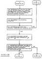
- control element 35in controlling the buffer 32 will be described in connection with the flow chart depicted in FIGs. 6A through 6D.
- control element 35utilizes the non-overlapping windows methodology as described above for collecting buffered cell traffic information; modifications to utilize the overlapping windows methodology will be readily apparent to those skilled in the art.
- FIG. 6A through 6Dit is assumed that the control element 35 utilizes the non-overlapping windows methodology as described above for collecting buffered cell traffic information; modifications to utilize the overlapping windows methodology will be readily apparent to those skilled in the art.
- the control element 35first establishes an initial buffer contents threshold value (step 100), which may be selected to be a predetermined fraction of "B," the number of storage locations in the buffer 32, or it may be selected in response to prior experience with other similar networks or, if the control element 35 is part of a routing node 11(n) which is being added to the network 10, with other routing nodes in the same network 10.
- an initial buffer contents threshold value(step 100) which may be selected to be a predetermined fraction of "B," the number of storage locations in the buffer 32, or it may be selected in response to prior experience with other similar networks or, if the control element 35 is part of a routing node 11(n) which is being added to the network 10, with other routing nodes in the same network 10.
- the control element 35After establishing an initial buffer contents threshold value, the control element 35 establishes an interval counter and loads it with the selected value for "k" (step 101). The control element 35 will use the interval counter to determine when it has collected buffered cell traffic information for the entire window, after which it can determine whether and to what extent it is to adjust the value of the buffer contents threshold value. In addition, the control element establishes and initializes a partial packet discard counter (step 102). The control element 35 then enables the buffer 32 to operate as described above in connection with FIG. 3 (step 103). During operations in connection with step 103, the control element 35 increments the partial packet discard counter whenever it enables a packet to be discarded in connection with the partial packet discard methodology.
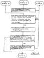
- the control element 35periodically determines whether the predetermined time interval has ended (step 104), and if so it determines values for P(t) and D(t) as the buffered cell traffic information and saves them as well as the value for the partial packet discard counter (step 105). Following step 105, the control element will decrement the interval counter (step 105) and determine whether the interval counter has counted out (step 107). At this point, it will be assumed that the interval counter has not counted out, in which case the control element 35 will not have collected buffered cell traffic information for the entire window, in which case the control element will return to step 102.
- the control element 35will perform steps 102 through 107 through a plurality of iterations, in each iteration determining and saving values for P(t) and D(t) and the partial packet discard counter as the buffered cell traffic information and decrementing the interval counter, until it determines in step 107 that the interval counter has counted out.
- the control elementsequences to a series of steps 110 through 118 to determine whether the buffer contents threshold value is to be updated, and, if so, to update it.
- the control element 35will, in response to the saved buffered cell traffic information P(t) and D(t), generate the average values P M (t) and D M (t) and the variance P ⁇ (t) (step 110).
- control elementwill then determine whether the sum of the saved values for the partial packet discard counter is greater than a selected fraction of the value of P M (t) (step 111), and if so decrement the buffer contents threshold value (step 112) and return to step 101 to resume operations at the beginning of another window.
- control element 35determines in step 111 that the sum of the saved values for the partial packet discard counter is not greater than the selected fraction of the value of P M (t), it will sequence to step 113 to determine whether the value of the variance P (t) is large enough to indicate that the average values P M (t) and D M (t) are reliable. If so, it proceeds to a sequence comprising steps 114 through 116 to determine whether the buffer contents threshold value is to be increased. Initially, the control element 35 generates a value for B-[X-P M (t)+P ⁇ (t)] (step 114) and determines whether that value is larger than the current value for the buffer contents threshold value (step 115). If the control element makes a positive determination in step 115, it sequences to step 116 to update the buffer contents threshold value to the value determined in step 114 and returns to step 101 to resume operations at the beginning of another window.
- control element 35determines in step 115 that the value determined in step 114 was not larger than the current value for the buffer contents threshold value, such that the buffer contents threshold value will not be increased, it will step to a sequence comprising steps 117 through 119 to determine whether the buffer contents threshold value is to be decreased. In those operations, the control element generates a value for and determines whether that value is smaller than the current value for the buffer contents threshold value (step 118). If the control element makes a positive determination in step 118, it sequences to step 119 to update the buffer contents threshold value to the value determined in step 118. Following either step 119, or step 118 if the control element 35 determines there that the value generated in step 117 is larger than the current value for the buffer contents threshold value, it will return to step 101 to resume operations at the beginning of another window.
- control element 35may make use of a variety of types of buffered cell traffic information and methodologiies, statistical and otherwise, instead of or in addition to the types of information described above.
- control element 35has been described as adjusting the buffer contents threshold value using statistical measures such as average and variance in for cell traffic, other statistical methods and measures may find utility.
- control element 35may be obtain the buffer contents threshold value from look-up tables or the like, which may be generated using the statistical methodologies described above and which identify buffer contents threshold values as a function of cell traffic.
- partial packet discard methodology and early packet discard methodology with adjustable buffer contents threshold valuemay be useful in a variety of types of networks in addition to networks such as network 10 which implement the ATM (asynchronous transfer mode) data transfer methodology.
- the network 10 in FIG. 1is shown as being connected to computer systems 12(m) to facilitate transfer of information thereamong, it will be appreciated that the network 10 may be connected to diverse types of devices for transferring a variety of types of information, including, but not limited, to devices for generating and receiving video information, digital imaging information, voice information and the like.
- control element 35may be implemented using digital hardware, a suitably programmed digital computer (such as a microprocessor) or a combination of digital hardware and a suitably programmed digital computer.
Landscapes
- Engineering & Computer Science (AREA)
- Computer Networks & Wireless Communication (AREA)
- Signal Processing (AREA)
- Data Exchanges In Wide-Area Networks (AREA)
Description
- The invention relates generally to the field of digital communications systems and moreparticularly to digital networks for facilitating communication of digital data in, for example, digitalimage, audio and video distribution systems and among digital computer systems.
- Digital networks have been developed to facilitate the transfer of information, including dataand programs, among digital computer systems and other digital devices. A variety of types ofnetworks have been developed and implemented using diverse information transfer methodologies.In some networks, such as the well-known Ethernet, a single wire is used to interconnect all of thedevices connected to the network. While this simplifies wiring of the network in a facility andconnection of the devices to the network, it results in generally slow information transfer, since thewire can only carry information, in the form of messages, from a single device at a time. Toalleviate this to some extent, in some Ethernet installations, the network is divided into a numberof sub-networks, each having a separate wire, with interfaces interconnecting the wires. In suchinstallations, wires can carry messages for devices connected thereto simultaneously, whichincreases the number of messages that can be transferred simultaneously. It is only when a deviceconnected to one wire needs to send a message to a device connected to another wire that wires intwo or more sub-networks will be used, making them unavailable for use by other devices connectedthereto.
- To alleviate this, networks have been developed in which communications are handledthrough a mesh of routing nodes. The computer systems and other devices are connected to variousones of the routing nodes. Since the routing nodes themselves are interconnected in a variety ofpatterns, a number of paths may be available between pairs of the devices, so that if one path iscongested, another may be used. Such an arrangement may result in a network which is morecomplicated than an Ethernet network, but it can provide substantially higher information transfer rates, particularly if optical fiber is used as the media interconnecting the routing nodes and devices.
- A problem which may arise with such networks is that, in such networks, a routing node or a device,when it is receiving information from another routing node or device in the network, does not havea mechanism to provide "flow-control" information to the transmitting routing node or device.While this does reduce the cost of a network, it may result in congestion, in which a routing nodemay receive information at a rate faster than it can transmit it.
- This problem has been addressed in one type of network, namely, a network implementedin accordance with the ATM ("Asynchronous Transfer Mode") methodology. In such a network,a "packet" of data is transmitted from a source device to one or more destination devices in a seriesof "cells." If a routing node detects congestion, such that it is receiving cells faster than it cantransmit them, it can make use of several mechanisms. In one such mechanism, identified as "earlypacket discard," which may be used if a moderate amount of congestion is experienced, the routingnode first refuses to accept cells related to any new packets, but it attempts to continue transferringcells associated with packets it has already begin transferring. This may alleviate the congestiondownstream of the routing node, or at least provide that it does not increase. However, thecongestion may continue increasing to a point where the node activates a second mechanism,identified as "partial packet discard." In the partial packet discard mechanism, if the routing node,due to increased congestion, has to drop one cell for a packet that it has begun transferring, it willcontinue dropping the cells from the same packet because all of the cells for a packet are requiredto correctly reassemble the packet at the destination. If the partial packet discard mechanism isactivated due to congestion, partial packet discard should reduce it, but the packets which have beendiscarded must be retransmitted by the source in any case, so the routing nodes's resources used totransfer the cells prior to activation of the partial packet discard mechanism were wasted.
- EP,0,596,200 discloses such a system, in which subsequent cells are discarded if theyrelate to a packet which has had a previous cell discarded.
- The invention, as defined by
claims - In brief summary, in one aspect the invention provides a computer network including aplurality of routing nodes, each routing node being connected to selected ones of the other routingnodes and at least some ofthe routing nodes being connected to one of a plurality of packet sourcesand/or one of a plurality of packet destinations. Each routing node routes packets that are generatedby the packet sources to respective ones of the packet destinations, each packet including a pluralityof serially-transmitted cells. At least some of the routing nodes, in response to detection of aselected degree of congestion, enable an "early packet discard control arrangement," in which theydiscards cells which they receive which are related to packets for which they did not receive a cellprior to enabling the early packet discard control arrangement. The routing nodes periodicallyadjust the degree of congestion at which they will enable the early packet discard controlarrangement in relation to information corresponding to rates of reception and transmission of cellsover a selected period of time prior thereto.
- In a further aspect, the invention provides a routing node for use in connection with acomputer network. The computer network includes a plurality of routing nodes for transferringpackets, each packet including a plurality of serially-transmitted cells, generated by a plurality ofpacket sources to respective ones of a plurality of packet destinations. The routing node comprisesa buffer and a buffer control. The buffer receives and buffers cells to be transmitted to other routingnodes in the network or to a packet destination. The buffer control selectively enables the buffer toreceive and buffer cells. The buffer control enables an early packet discard control arrangement inwhich, when the buffer instantaneously buffers a selected number of cells, it disables the buffer frombuffering cells which are related to packets for which it did not begin receiving cells prior toenabling the early packet discard control arrangement mechanism. The buffer control periodically adjusts the selected number in relation to information corresponding to rates of reception andtransmission of cells over a selected period of time prior thereto.
- This invention is pointed out with particularity in the appended claims. The above andfurther advantages of this invention may be better understood by referring to the followingdescription taken in conjunction with the accompanying drawings, in which:
- FIG. 1 schematically depicts a computer network including a routing node constructed inaccordance with the invention;
- FIG. 2 schematically illustrates the structure of message packets and constituent messagecells transferred over the network depicted in FIG. 1;
- FIG. 3 schematically depicts a routing node, constructed in accordance with the invention,which is used in the computer network depicted in FIG. 1;
- FIGs. 4 and 5 are a diagrams useful in understanding the operation of the routing nodedepicted in FIG. 3; and
- FIGs. 6A through 6D comprise a flow-chart illustrating the operations of the routing nodein accordance with the invention.
- FIG. 1 schematically depicts a
computer network 10 including a plurality of routing nodes11(1) through 11(N) (generally identified by reference numeral 11n)) for transferring signalsrepresenting data among a number of devices, which in FIG. 1 are represented by computer systems12(1) through 12(M) (generally identified by reference numeral 12(m)). The computer systems 12(m), as is conventional, process data, in accordance with their program instructions to generateprocessed data. In their processing, a computer system 12(mS) (subscript "S" referencing "source")may, as a source computer system, need to transfer data, processed data and/or program instructions(all of which will be referred to herein generally as "information") to another, destination, computersystem 12(mD) (subscript "D" referencing "destination"), which may need to use the transferredinformation in its operations. Each computer system 12(m) is connected over a communication link,generally identified by reference numeral 13(p), to a routing node 11(n) to facilitate transmissionof data thereto or the reception of data therefrom. The routing nodes 11(n) are interconnected bycommunication links, also generally identified by reference numeral 13(p) to facilitate the transferof data thereamong. The communication links 13(p) may utilize any convenient data transmissionmedium; in one embodiment, the transmission medium of each communication link 13(p) is selectedto comprise one or more fiber optic links. Each communication link 13(p) is preferably bi-directional,allowing the routing nodes 11(n) to transmit and receive signals among each other andwith computer systems 12(m) connected thereto over the same link; in the embodiment in which thecommunication links 13(p) are fiber optic links, two optical fibers will be provided for eachcommunication link 13(p), each of which facilitates unidirectional transfer of optical signals. - In one embodiment, the
network 10 transfers data using the well-known "ATM"("Asynchronous Transfer Mode") transfer methodology. That methodology is described in detailin C. Partridge,Gigabit Networking, (Reading MA: Addison Wesley Publishing Company, 1994),primarily inchapters packet 20 to be transmitted froma source computer system 12(mS) to a destination computer system 12(mD), the source computersystem 12(mS) allocates thedata packet 20 to a plurality of "cells," identified CELL(1) throughCELL(1) (generally identified "CELL(i)"), for transmission serially over the communication link13(p) to initiate transfer thereof over thenetwork 10. Each cell includes a header portion HDR(i)and a data portion DATA(i), with the header portion HDR(i) including path identifier and "virtual circuit" information for controlling the transfer of the cell over thenetwork 10, and the data portionDATA(i) containing data from thepacket 20. The data portion DATA(i) of each cell is of fixed,predetermined length (in one embodiment forty-eight bytes) and so the source computer system12(ms) will pad the data in the last data portion DATA(i) if the amount of data in thepacket 20 isnot an integral multiple of the size of the data portion DATA(i) of each cell to ensure that the lastdata portion DATA(i) has the required length. - As noted above, the source computer system 12(mS) transmits the series of cells CELL(1)through CELL(i) generated from a
data packet 20 in order, and thenetwork 10 is to deliver the cellsto the destination computer system 12(mD) in the order in which they are transmitted. Thedestination computer system 12(mD) must receive all of the cells transmitted by the source computersystem 12(mS) in order to reconstruct thepacket 20. In the aforementioned ATM transfermethodology, the cells do not contain ordering information; and so the destination computer system12(mD) determines the proper order to reconstitute thepacket 20 from the order in which it receivesthe cells. The last cell CELL(i) includes a set end of packet flag, designated EOP in FIG. 2, toindicate that it is the last cell for the packet. - As further noted above, header portion HDR(i) includes path identifier and "virtual circuit"information, both of which control the transfer of the cell over the
network 10. Each routing node11(n) uses the path identifier and virtual circuit information for a cell CELL(p) that it receives toover an input communication link identify an output communication link over which it is to transmitthe cell to the next routing node or the destination computer system 12(mD). The virtual circuitinformation in the headers HDR(i) of the cells CELL(i) associated with apacket 20 will be the same,but it will differ for cells associated with different packets. Although a destination computer system12(mD) will be receiving cells generated for aspecific packet 20 in the order of the data in thepacket, it may be contemporaneously receiving cells from thenetwork 10 which originated at severalsource computer systems 12(mS), which cells may be received in an interleaved manner. The virtualcircuit information in each cell CELL(i) will enable the destination computer system 12(mD) todetermine thepacket 20 with which the cell is associated. - The routing nodes 11(n) comprising
network 10 all have generally the same structure, whichwill be described in connection with FIG. 3. With reference to FIG. 3, each routing node 11(n)includes aninput interface 30, abuffer 32, and anoutput interface 34, all under control of acontrolelement 35. To facilitate bi-directional communications, theinput interface 30 andoutput interface 34 will be connected to all of the communication links 13(p) to which the routing node 11(n) isconnected to facilitate reception of signals from, and transmission of signals to, others of the routingnodes in thenetwork 10 or ones of the computer systems 12(m) to which the routing node 11(n) isconnected. In the case of the above-described embodiment in which the communication links 13(p)are in the form of optical fibers, theinput interface 30 is connected to particular ones of thecommunication links, namely, input communication links 13(p)(i), over which the routing node11(n) receives the optical signals, and theoutput interface 34 is connected to others of thecommunication links, namely, output communication links 13(p)(o), over which the routing nodetransmits the optical signals. It will be appreciated that each input communication links 13(p)(i) willconstitute an output communication link over which a computer system 12(m) or another routingnode in thenetwork 11 transmits signals, and each output communication link 13(p)(o) willconstitute an input communication link over which a computer system 12(m) or another routing nodein thenetwork 11 receives signals. - The
input interface 30, under control of thecontrol element 35, receives optical signalsdefining a cell CELL (n) from the input communication links and converts them to electrical form,which it supplies to buffer 32 for buffering. Thebuffer 32 may comprise a unitary buffer whichreceives and buffers cells CELL(i) in electrical form generated by theinput interface 30 in responseto the optical cells it receives from all of the input communication links 13(p)(i). Alternatively, thebuffer 32 may comprise a plurality of buffer sections allocated to the separate output communicationlinks 13(p)(o), each of which will receive and buffer cells CELL(i) to be transmitted over from oneor a selected sub-set of the output communication links 13(p)(o). Theoutput interface 34 willgenerally transmit cells CELL(i) to be transmitted over each output communication link 13(p)(o)in the order in which they are received and loaded into thebuffer 32. Theoutput interface 34receives the cells CELL(i) which are buffered in thebuffer 32, converts the cells, which at this point are still in electrical signal form, to optical form and couples the optical signals over the outputcommunication links 13(p)(o). For each cell CELL(i) transmitted by theoutput interface 34, thecontrol element 35 may update the header portion HDR(i) with a new path identifier and virtualcircuit identifier as it is being transmitted. - As noted above, the
control element 35 enables cells CELL(i) received from the inputcommunication links 13(p)(i) to be buffered in thebuffer 32. If the input buffer fills faster than thecells CELL(i) can be drained from thebuffer 32 and transmitted over the output communicationlinks 13(p)(o), thebuffer 32 may overflow, in which case the subsequently-received cells would notbe buffered, but instead would be lost. Thecontrol element 35 makes use of two mechanisms inconnection with the possibility of buffer overflow. In accordance with one mechanism, identifiedas "early packet discard," thecontrol element 35 establishes a buffer contents threshold value,which, in accordance with the invention, it may adjust as described below. When the number ofcells CELL(i) buffered in thebuffer 32 is greater than the buffer contents threshold value, thecontrolelement 35 will enable thebuffer 32 to continue buffering of cells CELL(i) associated with packetsthat it has previously enabled to be buffered; however, if first cell for a new packet is receivedwhile such a condition exists, thecontrol element 35 will not allow that cell CELL(0) andsubsequently-received cells associated with the same packet to be buffered in thebuffer 32. - In accordance with the second mechanism, identified as "partial packet discard," if the
buffer 32 in fact overflows despite application of the early packet discard mechanism, thecontrol element 35 will disable thebuffer 32 from buffering cells CELL(i) while it (the buffer) is full, and will allowthose cells to be discarded. In addition, even after the number of cells buffered in thebuffer 32 hasbeen reduced so that it is no longer overflowing, thecontrol element 35 will continue discardingcells associated with packets for which cells were discarded while thebuffer 32 was in the overflowcondition, using in particular the path and virtual circuit identifier information in the header portionsHDR(i) of the respective cells, until it detects a cell for which the EOP end of packet flag is set.Since, in the ATM transfer methodology, the cells CELL(i) are transmitted and received in cellorder, when the routing node 11(n) begins discarding cells associated with a packet, the transfer ofsubsequent cells associated with the packet would be a waste of routing node resources, since the destination would not be provided with all of the cells required to reconstruct the packet. Theprimary exception is the last cell, since the set EOP end of packet flag will notify the destinationcomputer system 12(mD) which received the cell that it was the last cell it would receive related tothe packet. Thereafter, the destination and source computer systems 12(mD) and 12(mS) may makeuse of predetermined error recovery techniques, such as facilitating retransmission of the discardedpacket. - By use of the early packet discard methodology, the control element will, to some extent,reduce the rate at which cells are buffered, increasing the likelihood that it will be able to transferall of the cells CELL(i) associated with the packets that it has already started transferring.
- As described above, in activating the early packet discard methodology, and in accordancewith the invention, the
control element 35 of a router node 11(n) does not use a fixed buffer contentsthreshold value, but instead controls and adjusts the buffer contents threshold value in relation topacket and cell traffic through the router node 11(n). The operations performed by thecontrolelement 35 in controlling and adjusting the buffer contents threshold value will be described inconnection with FIGs. 4 and 5 and the flowchart in FIGS. 6A through 6D. With reference initiallyto FIGs. 4 and 5, those FIGS. schematically depict a representation of thebuffer 32. As isconventional, thebuffer 32 comprises a plurality of storage locations (not separately shown); in theembodiment depicted in FIG. 4, thebuffer 32 is shown as comprising "B" storage locationsextending from an output storage location "1" at anoutput end 40 depicted at the right end of thebuffer 32 as shown in FIG. 4, to an input storage location "B" at aninput end 41 depicted at the leftend of thebuffer 32. Cells are coupled to thebuffer 32 from theinput interface 30 through over oneormore input lines 42 connected to theinput end 41, and are drained from thebuffer 32 through theoutput end 40 and transferred to theoutput interface 34 over one or more output lines 43. In therepresentation depicted in FIG. 4, as a cell is loaded into thebuffer 32 through theinput end 41, itis packed on top of previously-loaded undrained cells, and as each cell is drained from the buffer,the undrained cells in the buffer will shift toward theoutput end 40, so that so that undrained cellswill be packed toward theoutput end 40. - Also shown in FIG. 4 are three parameters, identified as values "E," X" and "P" which areuseful in connection with understanding of the early packet discard mechanism in accordance withthe invention. The parameter "E" depicted in FIG. 4 corresponds to the above-described buffercontents threshold value, and a dashed
line 44 is shown at a position in thebuffer 32 representing"E" storage locations from theoutput end 40 of FIG. 4. Accordingly, when thebuffer 32 containsa sufficient number of cells that a cell is occupying the E-th storage location, at dashedline 44, thecontrol element 35 activates the early packet discard methodology. The parameter "X" identifiesthe number of storage locations in the remaining portion of the buffer beyond the "E-th" storagelocation, and in any case has a value corresponding to "B-E." It will be appreciated that the valueof "X" identifies the number of storage locations that thebuffer 32 may use in buffering cells inputthereto following activation of the early packet discard methodology, before thebuffer 32 will befull and it will begin activating the partial packet discard methodology. The value "P" identifiesnumber of storage locations extending from a second dashedline 45 shown in FIG. 4 to the laststorage location in the buffer. The second dashedline 45 represents the last storage location in thebuffer 32 which contains a cell with a set EOP end of packet flag, indicating that that is the last cellassociated with a packet. - The
control element 35 may use the values of parameters "E" (that is, the current value ofthe buffer contents threshold value), "X" and "P" (which it can determine using message trafficstatistics it can gather as described below) along with the value of "B" (which corresponds thenumber of storage locations in the buffer 32), to adjust the value of the buffer contents thresholdvalue, in particular to increase it as shown in FIG. 4 so as to enlarge the portion of thebuffer 32 thatwill be filled before it (the control element 35) activates the early packet discard methodology. Asnoted above, the portion of thebuffer 32 between thethreshold line 44 and the last "B-th" storagelocation of thebuffer 32 is provided to reduce the likelihood of thecontrol element 35 proceedingto the partial packet discard methodology after it has activated the early packet discard methodology.Accordingly, - (i) if the number of cells buffered in
buffer 32 is greater than the buffer contents thresholdvalue, such that thecontrol element 35 has activated the early packet discard methodology, and - (ii) if, for packets whose cells the
buffer 32 is still buffering under the early packet discardmethodology (because the cells were associated with packets that were being buffered when thecontrol element activated the early packet discard methodology), all of the cells with set EOP endof packet flags are located in the region of thebuffer 32 beyond the storage location correspondingto the buffer contents threshold value represented byline 44, and below the storage locationrepresented by dashed line 45 (that is, the value of "X-P" in FIG. 4 is positive),
the buffer contents threshold value "E" can be enlarged so that the region designated "X-P" in FIG.4 is located at the upper end of thebuffer 32. This will provide that thebuffer 32 has sufficientexcess space, beyond the threshold at which point the early packet discard methodology is activated,to be able to buffer at least to the last cells associated with the packets that it had been bufferingwhen the early packet discard methodology is activated. - FIG. 5 also shows the
buffer 32 as described above, also shows parameter "E," which hasthe same references as in FIG. 4, and also shows a fourth parameter, namely, parameter "D," whichis also useful connection with understanding of the early packet discard mechanism in accordancewith the invention, in particular a circumstance in which the buffer contents threshold value can bereduced. In particular, the value of parameter "D" corresponds to the largest number of storagelocations which contains a cell over a selected time period, which is represented by the dashedline 46 in FIG. 5. If the value of parameter "D" is less than the current value of the parameter E (thebuffer contents threshold value), the buffer contents threshold value can be reduced to correspondto the value of parameter "D," preferably as increased by a small margin "δ" which may serve toreflect possible inaccuracies in measuring or predicting the value of parameter "D." If the value ofthe buffer contents threshold value is reduced as described above in connection with FIG. 5, thenumber of storage locations represented by parameter "X," located beyond the storage locationcorresponding to the buffer contents threshold value, will be increased. - The
control element 35 may increase the value of the buffer contents threshold value, asdescribed above in connection with FIG. 4, and decrease the value of the buffer contents thresholdvalue, as described above in connection with FIG. 5, in relation to buffered cell traffic information which it generates as described below. It will be appreciated that increasing the value of the buffercontents threshold value will increase the number of cells that thebuffer 32 will buffer before thecontrol element 35 will activate the early packet discard methodology, and it will also reduce theamount of buffering available for avoiding partial packet discard if cell traffic increases. On theother hand, reducing the value of the buffer contents threshold value will decrease the number ofcells that thebuffer 32 will buffer before the control element will activate the early packet discardmethodology. This may increase the likelihood that thecontrol element 35 will activate the earlypacket methodology relatively early, thereby increasing the likelihood that packets will be discarded,but it will increase the amount of buffering, in the portion of thebuffer 32 beyond the storagelocation identified by the buffer contents threshold value, which is available for cells of packets thatthe router node 11(n) has already partially transferred, thereby reducing the likelihood that thebuffer 32 will overflow and the control element will have to activate the partial packet discardmethodology. Thecontrol element 35 may periodically determine an amount to increase or decreasethe buffer contents threshold value, using the methodologies described above in connection withFIGs. 4 and 5, based on the determined buffered cell traffic information. - The
control element 35 in one embodiment gathers buffered cell traffic information asfollows. In addition to controlling the buffering of the cells CELL(i) by thebuffer 32, thecontrolelement 35 at periodic time intervals "t" determines values for parameter D(t) (related to parameterD described above in connection with FIG. 5), the identification of the storage location whichcontains the last cell CELL(i) buffered in thebuffer 32, and parameter P(t) (related to parameter Pdescribed above in connection with FIG. 4), the position of the storage location in thebuffer 32which contains the last cell CELL(i) whose EOP end of packet flag is set. In addition, thecontrolelement 35 determines values for a parameter PPD(t), which corresponds to the number of packetswhich thecontrol element 35 enables to be discarded in response to the partial packet discardmethodology. - In response to the gathered buffered cell traffic information, the
control element 35determines whether the value of the buffer contents threshold value is to be adjusted. Initially, thecontrol element 35 determines whether the value of the buffer contents threshold value is to be adjusted in response to a selected relationship between the value of parameter PPD(t) (that is, thenumber of packets discarded in response to the partial packet discard methodology) and the valueof the parameter P(t), in particular in one embodiment determining whether the value of parameterPPD(t), is above a selected percentage of parameter P(t). If so, thecontrol element 35 5 reduces thevalue of the buffer contents threshold value by a selected amount, which in that same embodimentis selected also in connection with the relationship between the values of parameter PPD(t) and ofparameter P(t). - If the
control element 35 determines that the value of the parameter PPD(t) is below theselected level, such that the buffer contents threshold value will not be adjusted in response to arelation between the parameters PPD(t) and P(t), it determines whether the buffer contents thresholdvalue is to be adjusted in response to a relationship among the values of parameters D(t), P(t) andthe size of the buffer, B. Initially, thecontrol element 35 determines values of these parameters overa period of "K" prior time intervals and generates statistics PM(t) as the average value of parameterP(t) and Pσ(t), as the variance of the value of parameter P(t), DM(t) as the average value of parameterD(t). Thecontrol element 35 examines the value of statistic Pσ(t), the variance of parameter P(t),to determine whether the values of parameters P(t) and D(t) and the statistics PM(t) and DM(t) are"reliable" to facilitate adjustment of the buffer contents threshold value. If the value of the variancestatistic Pσ(t) is relatively small, the values of parameter P(t) determined over the "K" time intervalsare all relatively close to the value of its average, statistic PM(t), which indicates that the values ofparameters P(t) and D(t) and the statistics PM(t) and DM(t) are sufficiently "reliable" that they maybe used to adjust the buffer contents threshold value. On the other hand, if the value of the variancestatistic Pσ(t) is relatively large, the values of parameter P(t) determined over the "K" time intervalsare all widely distributed, which indicates that the values of the parameters and statistics arerelatively unreliable, and that they should not be used to adjust the buffer contents threshold value. - If the
control element 35 determines that the variance statistic Pσ(t) indicates that the valuesof parameters P(t) and D(t) and the statistics PM(t) and DM(t) are sufficiently "reliable" that they maybe used to adjust the buffer contents threshold value, it generates the adjusted value generally as described above in connection with FIGs. 4 and 5. In particular, thecontrol element 35 firstdetermines whether it is to increase the buffer contents threshold value. In making thatdetermination, thecontrol element 35 determines a value for B-[X-(PM(t)+Pσ(t))], and if it is largerthan the current value for "E," the buffer contents threshold value, it will be used to update thecurrent value for the buffer contents threshold value. It will be appreciated that the value"[X-(PM(t)+Pσ(t))]" is analogous to the value "X-P" described above in connection with FIG. 4, butthe sum of the average statistic "PM(t)" and the variance "Pσ(t)," to provide a margin for error, hasbeen substituted for the addend "P." - If the
control element 35 determines that the buffer content threshold value is not to beincreased, it will determine whether it is to be decreased. In that operation, it generates a value forand if it is less than the current value for the buffer contents threshold value, it will be used to updatethe current value for the buffer contents threshold value. It will be appreciated that the value corresponds to the margin "δ" described above in connection with FIG. 5.
- The control element will periodically perform these operations to maintain the buffercontents threshold value at a level determined in response to the buffered cell traffic informationgathered over a window defined by a selected number "k" of prior time intervals. The
controlelement 35 may adjust the buffer contents threshold value at the end of each time interval, using thestatistics gathered over overlapping windows each defined by the previous "k" time intervals, or itmay adjust the buffer content value at the end of each non-overlapping window defined by "k" timeintervals. It will be appreciated that the value of "k" will determine a sensitivity level for theadjustment, with larger values of "k" reducing the sensitivity of the adjustment to recent cell trafficstatistics, and smaller values of "k" increasing the sensitivity of the adjustment to recent cell trafficstatistics. In addition, if thecontrol element 35 uses the non-overlapping methodology, it will be appreciated that larger values of "k" will increase the time between updates, and smaller values of"k" will decrease the time between updates. In one embodiment, the value of "k" is selected tocorrespond to twice the maximum round trip time for a cells to be transferred between computersystems 12(m) over thenetwork 10, divided by the line rate, so that the updates to the buffercontents threshold value will also reflect changes in cell traffic caused by flow control arrangementswhich may be activated by the computer systems 12(m). - With this background, the operations performed by the
control element 35 in controlling thebuffer 32 will be described in connection with the flow chart depicted in FIGs. 6A through 6D. Inthe operations depicted in FIGs. 6A through 6D, it is assumed that thecontrol element 35 utilizesthe non-overlapping windows methodology as described above for collecting buffered cell trafficinformation; modifications to utilize the overlapping windows methodology will be readily apparentto those skilled in the art. With reference to FIG. 6A, thecontrol element 35 first establishes aninitial buffer contents threshold value (step 100), which may be selected to be a predeterminedfraction of "B," the number of storage locations in thebuffer 32, or it may be selected in responseto prior experience with other similar networks or, if thecontrol element 35 is part of a routing node11(n) which is being added to thenetwork 10, with other routing nodes in thesame network 10. - After establishing an initial buffer contents threshold value, the
control element 35establishes an interval counter and loads it with the selected value for "k" (step 101). Thecontrolelement 35 will use the interval counter to determine when it has collected buffered cell trafficinformation for the entire window, after which it can determine whether and to what extent it is toadjust the value of the buffer contents threshold value. In addition, the control element establishesand initializes a partial packet discard counter (step 102). Thecontrol element 35 then enables thebuffer 32 to operate as described above in connection with FIG. 3 (step 103). During operations inconnection withstep 103, thecontrol element 35 increments the partial packet discard counterwhenever it enables a packet to be discarded in connection with the partial packet discardmethodology. - In addition, during its operations in connection with
step 103, thecontrol element 35periodically determines whether the predetermined time interval has ended (step 104), and if so itdetermines values for P(t) and D(t) as the buffered cell traffic information and saves them as wellas the value for the partial packet discard counter (step 105). Followingstep 105, the controlelement will decrement the interval counter (step 105) and determine whether the interval counterhas counted out (step 107). At this point, it will be assumed that the interval counter has not countedout, in which case thecontrol element 35 will not have collected buffered cell traffic informationfor the entire window, in which case the control element will return to step 102. - The
control element 35 will performsteps 102 through 107 through a plurality of iterations,in each iteration determining and saving values for P(t) and D(t) and the partial packet discardcounter as the buffered cell traffic information and decrementing the interval counter, until itdetermines instep 107 that the interval counter has counted out. When that occurs, the controlelement sequences to a series ofsteps 110 through 118 to determine whether the buffer contentsthreshold value is to be updated, and, if so, to update it. Initially, thecontrol element 35 will, inresponse to the saved buffered cell traffic information P(t) and D(t), generate the average valuesPM(t) and DM(t) and the variance Pσ(t) (step 110). The control element will then determine whetherthe sum of the saved values for the partial packet discard counter is greater than a selected fractionof the value of PM(t) (step 111), and if so decrement the buffer contents threshold value (step 112)and return to step 101 to resume operations at the beginning of another window. - On the other hand, if the
control element 35 determines instep 111 that the sum of the savedvalues for the partial packet discard counter is not greater than the selected fraction of the value ofPM(t), it will sequence to step 113 to determine whether the value of the variance P (t) is largeenough to indicate that the average values PM(t) and DM (t) are reliable. If so, it proceeds to asequence comprising steps 114 through 116 to determine whether the buffer contents threshold valueis to be increased. Initially, thecontrol element 35 generates a value for B-[X-PM(t)+Pσ(t)] (step114) and determines whether that value is larger than the current value for the buffer contentsthreshold value (step 115). If the control element makes a positive determination instep 115, it sequences to step 116 to update the buffer contents threshold value to the value determined instep 114 and returns to step 101 to resume operations at the beginning of another window. - Finally, if the
control element 35 determines instep 115 that the value determined instep 114 was not larger than the current value for the buffer contents threshold value, such that the buffercontents threshold value will not be increased, it will step to asequence comprising steps 117through 119 to determine whether the buffer contents threshold value is to be decreased. In thoseoperations, the control element generates a value forand determineswhether that value is smaller than the current value for the buffer contents threshold value (step118). If the control element makes a positive determination in
step 118, it sequences to step 119 toupdate the buffer contents threshold value to the value determined instep 118. Following eitherstep 119, or step 118 if thecontrol element 35 determines there that the value generated instep 117 islarger than the current value for the buffer contents threshold value, it will return to step 101 toresume operations at the beginning of another window. - It will be appreciated that numerous modifications may be made to the router node 11(n) andthe
control element 35. For example, thecontrol element 35 may make use of a variety of types ofbuffered cell traffic information and methodologiies, statistical and otherwise, instead of or inaddition to the types of information described above. In addition, although thecontrol element 35has been described as adjusting the buffer contents threshold value using statistical measures suchas average and variance in for cell traffic, other statistical methods and measures may find utility.In addition, although the control element has been described as actually generating the statisticalmeasures used to adjust the buffer contents threshold value while the node 11(n) is in operation, itwill be appreciated thecontrol element 35 may be obtain the buffer contents threshold value fromlook-up tables or the like, which may be generated using the statistical methodologies describedabove and which identify buffer contents threshold values as a function of cell traffic. - In addition, it will be appreciated that the partial packet discard methodology and earlypacket discard methodology with adjustable buffer contents threshold value may be useful in avariety of types of networks in addition to networks such as
network 10 which implement the ATM(asynchronous transfer mode) data transfer methodology. - Although the
network 10 in FIG. 1 is shown as being connected to computer systems 12(m)to facilitate transfer of information thereamong, it will be appreciated that thenetwork 10 may beconnected to diverse types of devices for transferring a variety of types of information, including,but not limited, to devices for generating and receiving video information, digital imaginginformation, voice information and the like. - It will also be appreciated by those skilled in the art that the
control element 35 may beimplemented using digital hardware, a suitably programmed digital computer (such as amicroprocessor) or a combination of digital hardware and a suitably programmed digital computer.


Claims (41)
- A computer network (10) including a plurality ofrouting nodes (11(1) through 11(M)), each routing node being connected toselected ones of the other routing nodes and at leastsome of the routing nodes being connected to one of aplurality of packet sources (12(1) through 12(7)) or one of a plurality ofpacket destinations (12(1) through 12(7)), each routing node routing packetsgenerated by the packet sources to respective ones ofthe packet destinations, each packet including aplurality of serially-transmitted cells, at least someof said routing nodes, in response to detection of aselected degree of congestion, enabling an early packetdiscard control arrangement in which they discard cellswhich they receive which are related to packets forwhich they did not receive a cell prior to activationof the early packet discard mechanism, at least some ofsaid routing nodes periodically adjusting the degree ofcongestion at which they will activate the early packetdiscard mechanism in relation to informationcorresponding to rates of reception and transmission ofcells over a selected period of time prior thereto.
- A routing node for use in connection with acomputer network (10) including a plurality of routingnodes (11 (1) through 11 (6)), the routing node being connected to selectedones of the other routing nodes, and at least some ofthe routing nodes being connected to one of a pluralityof sources or one of a plurality of destinations, eachrouting node routing packets generated by the sourcesto respective ones of the destinations, each packetincluding a plurality of serially-transmitted cells,said routing node comprising:a buffer for receiving and buffering cells to betransmitted to other routing nodes in the network or toa packet destination; anda buffer control for selectively enabling thebuffer to receive and buffer cells, the buffer control enabling an early packet discard control arrangement inwhich, in response to the buffer contemporaneouslybuffering a selected threshold number of cells, itdisables the buffer from receiving and bufferingreceived cells which are related to packets for whichit did not begin receiving cells prior to enabling theearly packet discard control arrangement mechanism, thebuffer control periodically adjusting the thresholdnumber in relation to information corresponding to arate at which said buffer is buffering cells over aselected period of time prior thereto.
- A routing node as defined in claim 2 in whichthe buffer control periodically adjusts the thresholdnumber in relation to a buffered cell value as aselected function of the number of cells buffered bysaid buffer over said selected period of time.
- A routing node as defined in claim 3 in whichsaid selected function is an averaging function, inwhich the buffer control periodically adjusts thethreshold number in relation to an average bufferedcell value as an average of the number of cellsbuffered by said buffer over said selected period oftime.
- A routing node as defined in claim 4 in whichsaid buffer control comprises:a threshold store for storing a threshold value;an occupancy statistics generator for generatingthe average buffered cell value corresponding to theaverage number of cells buffered by said buffer oversaid selected period of time;a comparator for comparing the threshold valuestored by said threshold store to said average bufferedcell value; anda control module for periodically enabling theoccupancy statistics generator to generate said averagebuffered cell value and said comparator to compare the threshold value stored by said threshold store to saidaverage buffered cell value, the control moduleenabling said average buffered cell value to be storedin said threshold store if the comparator determinesthat the average buffered cell value is less than thethreshold value stored by said threshold store.
- A routing node as defined in claim 5 in whichsaid buffer control further includes a statisticsreliability assessment module for generating astatistics reliability assessment value, the controlmodule using the statistics reliability assessmentvalue in determining whether to enable said averagebuffered cell value to be stored in said thresholdstore.
- A routing node as defined in claim 6 in whichat least some cells received by said routing nodeinclude an end-of-packet indicator which indicate thateach respective cell is an end of a packet, and inwhich said buffer comprises a series of storagelocations each for storing one of said cells, thebuffer control further periodically adjusting thethreshold number in relation to a second selectedfunction of the last of said storage locations in whicha cell is stored which has an end-of-packet indicator,said statistics reliability assessment modulegenerating the statistics reliability assessment valueas a function of a variance value corresponding to thevariance of the last of the storage locations in whichsaid cell is stored which has an end-of-packetindicator.
- A routing node as defined in claim 4 in whichat least some cells received by said routing nodeinclude an end-of-packet indicator which indicate thateach respective cell is an end of a packet, and inwhich said buffer comprises a series of storagelocations each for storing one of said cells, the buffer control further periodically adjusting thethreshold number in relation to a second selectedfunction of the last of said storage locations in whicha said cell is stored which has an end-of-packetindicator.
- A routing node as defined in claim 8 in whichsaid second selected function is a variance function.
- A routing node as defined in claim 8 in whichthe buffer control comprises:a threshold store for storing a threshold value;an occupancy statistics generator including:an average buffered cell statistics generator forgenerating the average buffered cell valuecorresponding to the average number of cellsbuffered by said buffer over said selected periodof time;a variance generator for generating a variancevalue corresponding to the variance of the last ofthe storage locations in which a said cell isstored which has an end-of-packet indicator; anda composite statistics generator for generating acomposite statistics value as a selected functionof the average buffered cell value and thevariance value;a comparator for comparing the threshold valuestored by said threshold store to said compositestatistics value; anda control module for periodically enabling thestatistics generator to generate said compositestatistics value and said comparator to compare thethreshold value stored by said threshold store to saidcomposite statistics value, the control module enablingsaid composite statistics value to be stored in saidthreshold store if the comparator determines that thecomposite statistics value is less than the thresholdvalue stored by said threshold store.
- A routing node as defined in claim 10 inwhich said control module further uses the variancevalue in determining whether to enable said compositestatistics value to be stored in said threshold store.
- A routing node as defined in claim 10 inwhich said composite statistics generator generatessaid composite statistics value as a sum of saidaverage buffered cell value and an inverse of saidvariance value.
- A routing node as defined in claim 2 in whichat least some cells received by said routing nodeinclude an end-of-packet indicator which indicate thateach respective cell is an end of a packet, and inwhich said buffer comprises a series of storagelocations each for storing one of said cells, thebuffer control periodically adjusting the thresholdnumber in relation to the average of the last of thestorage locations storing a cell including an end-of-packetindicator over said selected period of time.
- A routing node as defined in claim 13 inwhich said buffer control comprises:a threshold store for storing a threshold value;an occupancy statistics generator for generatingan occupancy statistic value as a selected function ofthe last of the storage locations storing a cellincluding an end-of-packet indicator over said selectedperiod of time;a comparator for comparing the threshold valuestored by said threshold store to said occupancystatistic value; anda control module for periodically enabling theoccupancy statistics generator to generate saidoccupancy statistic value and said comparator tocompare the threshold value stored by said thresholdstore to said occupancy statistic value, the controlmodule enabling said occupancy statistic value to be stored in said threshold store if the comparatordetermines that the average buffered cell value isgreater than the threshold value stored by saidthreshold store.
- A routing node as defined in claim 14 inwhich said buffer comprises a predetermined number ofstorage locations, and said selected functioncorresponds to a difference function between (i) saidpredetermined number and (ii) a difference functionbetween (a) the predetermined number and the thresholdvalue and (b) the last of the storage locations storinga cell including an end-of-packet indicator over saidselected period of time.
- A routing node as defined in claim 14 inwhich said occupancy statistics generator includes:an occupancy value generator for generating anoccupancy value as said selected function of the lastof the storage locations storing a cell including anend-of-packet indicator over said selected period oftime;a variance generator for generating a variancevalue corresponding to the variance of the last of thestorage locations in which a said cell is stored whichhas an end-of-packet indicator; andan occupancy statistics value generator forgenerating said occupancy statistics value as a sum ofsaid occupancy value and said variance value.
- A routing node as defined in claim 14 inwhich said control module further uses the variancevalue in determining whether to enable said compositestatistics value to be stored in said threshold store.
- A routing node as defined in claim 2 in whichsaid buffer control further enables a partial packetdiscard arrangement in which, in response to the buffercontemporaneously buffering a second selected thresholdnumber of cells, it disables the buffer from receiving and buffering received cells, the buffer controlenabling said early packet discard control arrangementif the partial packet discard arrangement discards aselected number of cells.
- A routing node as defined in claim 18 inwhich said buffer control enables said early packetdiscard control arrangement if the partial packetdiscard arrangement discards a selected number of cellsover a predetermined partial packet discard timeperiod.
- A routing node as defined in claim 18 inwhich said buffer control enables said early packetdiscard control arrangement if the partial packetdiscard arrangement discards cells associated with aselected number of packets.
- A routing node as defined in claim 20 inwhich said buffer control enables said early packetdiscard control arrangement if the partial packetdiscard arrangement discards cells associated with aselected number of packets over said predeterminedpartial packet discard period.
- A method of operating a routing node, therouting node being for use in connection with a (12(1) through 12(7))computer network (10) including a plurality of routingnodes, the routing node being connected to selectedones of the other routing nodes (11(1) through 11(6)), and at least some ofthe routing nodes being connected to one of a pluralityof sources (12(1) through 12(7)) or one of a plurality of destinations (12(1) through 12(7)), eachrouting node routing cells generated by the sources torespective ones of the destinations, the methodincluding the steps of:receiving and buffering cells to be transmitted toother routing nodes in the network or to a packetdestination in a buffer; andselectively enabling the buffer to receive andbuffer cells, in the process enabling an early packet discard control arrangement in which, in response tothe buffer contemporaneously buffering a selectedthreshold number of cells, it disables the buffer fromreceiving and buffering received cells which arerelated to packets for which it did not begin receivingcells prior to enabling the early packet discardcontrol arrangement mechanism, the threshold numberbeing periodically adjusted in relation to informationcorresponding to a rate at which said buffer isbuffering cells over a selected period of time priorthereto.
- A method as defined in claim 22 in which thethreshold number is periodically adjusted in relationto a buffered cell value as a selected function of thenumber of cells buffered by said buffer over saidselected period of time.
- A method as defined in claim 23 in which saidselected function is an averaging function, in whichthe threshold number is periodically adjusted inrelation to an average buffered cell value as anaverage of the number of cells buffered by said bufferover said selected period of time.
- A method as defined in claim 24 in which saidperiodic adjustment step includes the steps of:storing a threshold value;generating the average buffered cell valuecorresponding to the average number of cells bufferedby said buffer over said selected period of time;comparing the threshold value stored by saidthreshold store to said average buffered cell value;andenabling said average buffered cell value to bestored in said threshold store if the average bufferedcell value is less than the threshold value stored bysaid threshold store.
- A method as defined in claim 25 in which the periodic adjustment step further includes the steps ofgenerating a statistics reliability assessment value,and using the statistics reliability assessment valuein determining whether to enable said average bufferedcell value to be stored in said threshold store.
- A method as defined in claim 26 in which atleast some cells received by said routing node includean end-of-packet indicator which indicate that eachrespective cell is an end of a packet, and in whichsaid buffer comprises a series of storage locationseach for storing one of said cells, the buffer controlfurther periodically adjusting the threshold number inrelation to a second selected function of the last ofsaid storage locations in which a cell is stored whichhas an end-of-packet indicator, the statisticsreliability assessment value being generated as afunction of a variance value corresponding to thevariance of the last of the storage locations in whicha said cell is stored which has an end-of-packetindicator.
- A method as defined in claim 24 in which atleast some cells received by said routing node includean end-of-packet indicator which indicate that eachrespective cell is an end of a packet, and in whichsaid buffer comprises a series of storage locationseach for storing one of said cells, the thresholdnumber being adjusted in relation to a second selectedfunction of the last of said storage locations in whicha said cell is stored which has an end-of-packetindicator.
- A method as defined in claim 28 in which saidsecond selected function is a variance function.
- A method as defined in claim 28 in which saidperiodic adjustment step includes the steps of:storing a threshold value in a threshold store;an occupancy statistics generation step including the steps of:generating the average buffered cell valuecorresponding to the average number of cellsbuffered by said buffer over said selected periodof time;generating a variance value corresponding to thevariance of the last of the storage locations in whicha said cell is stored which has an end-of-packetindicator; andgenerating a composite statistics value as aselected function of the average buffered cellvalue and the variance value;comparing the threshold value to said compositestatistics value; andperiodically enabling said composite statisticsvalue to be stored in said threshold store if thecomparison step determines that the compositestatistics value is less than the threshold valuestored by said threshold store.
- A method as defined in claim 30 in which saidvariance value is used in determining whether to storethe composite statistics value in said threshold store.
- A method as defined in claim 30 in which saidcomposite statistics value is generated as a sum ofsaid average buffered cell value and an inverse of saidvariance value.
- A method as defined in claim 22 in which atleast some cells received by said routing node includean end-of-packet indicator which indicate that eachrespective cell is an end of a packet, and in whichsaid buffer comprises a series of storage locationseach for storing one of said cells, the thresholdnumber being adjusted in relation to the average of thelast of the storage locations storing a cell includingan end-of-packet indicator over said selected period oftime.
- A method defined in claim 33 in which saidperiodic adjustment step includes the steps of:storing a threshold value in a threshold store;generating an occupancy statistic value as aselected function of the last of the storage locationsstoring a cell including an end-of-packet indicatorover said selected period of time;comparing the threshold value stored by saidthreshold store to said occupancy statistic value; andenabling said occupancy statistic value to bestored in said threshold store if the comparatordetermines that the average buffered cell value isgreater than the threshold value stored by saidthreshold store.
- A method as defined in claim 34 in which saidbuffer comprises a predetermined number of storagelocations, and said selected function corresponds to adifference function between (i) said predeterminednumber and (ii) a difference function between (a) thepredetermined number and the threshold value and (b)the last of the storage locations storing a cellincluding an end-of-packet indicator over said selectedperiod of time.
- A method as defined in claim 34 in which saidoccupancy statistics generation step includes the stepsof:generating an occupancy value as said selectedfunction of the last of the storage locations storing acell including an end-of-packet indicator over saidselected period of time;generating a variance value corresponding to thevariance of the last of the storage locations in whicha said cell is stored which has an end-of-packetindicator; andgenerating said occupancy statistic value as a sumof said occupancy value and said variance value.
- A method as defined in claim 34 in which saidvariance value is used in determining whether to enablesaid composite statistics value to be stored in saidthreshold store.
- A method as defined in claim 22 furtherincluding a partial packet discard step in which whilea second selected threshold number of cells are beingbuffered, the buffer is disabled from receiving andbuffering subsequently received cells, the early packetdiscard control arrangement being enabled if selectednumber of cells are discarded during the partial packetdiscard step.
- A method as defined in claim 38 in which saidearly packet discard control arrangement is enabled if,during the partial packet discard arrangement, aselected number of cells are discarded over apredetermined partial packet discard time period.
- A method as defined in claim 38 in which saidearly packet discard control arrangement is enabled ifcells associated with a selected number of packets arediscarded during the partial packet discard step.
- A method as defined in claim 40 in which saidearly packet discard control arrangement is enabled ifduring the partial packet discard step cells associatedwith a selected number of packets are discarded oversaid predetermined partial packet discard period.
Applications Claiming Priority (2)
| Application Number | Priority Date | Filing Date | Title |
|---|---|---|---|
| US445673 | 1995-05-22 | ||
| US08/445,673US5936939A (en) | 1995-05-22 | 1995-05-22 | Digital network including early packet discard mechanism with adjustable threshold |
Publications (3)
| Publication Number | Publication Date |
|---|---|
| EP0744850A2 EP0744850A2 (en) | 1996-11-27 |
| EP0744850A3 EP0744850A3 (en) | 1999-05-19 |
| EP0744850B1true EP0744850B1 (en) | 2002-10-09 |
Family
ID=23769794
Family Applications (1)
| Application Number | Title | Priority Date | Filing Date |
|---|---|---|---|
| EP96303586AExpired - LifetimeEP0744850B1 (en) | 1995-05-22 | 1996-05-21 | Digital network including early packet discard mechanism with adjustable threshold |
Country Status (4)
| Country | Link |
|---|---|
| US (1) | US5936939A (en) |
| EP (1) | EP0744850B1 (en) |
| JP (1) | JP3792782B2 (en) |
| DE (1) | DE69624169T2 (en) |
Cited By (6)
| Publication number | Priority date | Publication date | Assignee | Title |
|---|---|---|---|---|
| US7287084B1 (en) | 1999-07-15 | 2007-10-23 | F5 Networks, Inc. | Enabling encryption of application level persistence between a server and a client |
| US7346695B1 (en) | 2002-10-28 | 2008-03-18 | F5 Networks, Inc. | System and method for performing application level persistence |
| US7996886B1 (en) | 2002-09-03 | 2011-08-09 | F5 Networks, Inc. | Method and system for providing persistence in a secure network access |
| US8447871B1 (en) | 2000-03-21 | 2013-05-21 | F5 Networks, Inc. | Simplified method for processing multiple connections from the same client |
| US8566452B1 (en) | 2006-08-03 | 2013-10-22 | F5 Networks, Inc. | Intelligent HTTP based load-balancing, persistence, and application traffic management of SSL VPN tunnels |
| US8788665B2 (en) | 2000-03-21 | 2014-07-22 | F5 Networks, Inc. | Method and system for optimizing a network by independently scaling control segments and data flow |
Families Citing this family (138)
| Publication number | Priority date | Publication date | Assignee | Title |
|---|---|---|---|---|
| DE19703833A1 (en)* | 1997-02-01 | 1998-08-06 | Philips Patentverwaltung | Coupling device |
| JPH10271132A (en)* | 1997-03-27 | 1998-10-09 | Toshiba Corp | Flow control method in packet switching network |
| US5931915A (en)* | 1997-05-13 | 1999-08-03 | International Business Machines Corporation | Method for processing early arrival messages within a multinode asynchronous data communications system |
| IL122271A (en) | 1997-11-21 | 2001-01-11 | Eci Telecom Ltd | Apparatus and method for managing network congestion |
| CA2333595C (en)* | 1998-05-29 | 2007-10-16 | Siemens Aktiengesellschaft | Method for removal of atm cells from an atm communications device |
| EP0961441A1 (en) | 1998-05-29 | 1999-12-01 | Siemens Aktiengesellschaft | Method for removing ATM cells from an ATM communications system |
| GB2344974B (en)* | 1998-12-15 | 2003-07-23 | Roke Manor Research | Improvements in or relating to networks |
| US7382736B2 (en) | 1999-01-12 | 2008-06-03 | Mcdata Corporation | Method for scoring queued frames for selective transmission through a switch |
| US6381649B1 (en)* | 1999-02-05 | 2002-04-30 | Pluris, Inc. | Data flow monitoring at a network node using periodically incremented counters for comparison to predetermined data flow thresholds |
| US6578083B2 (en)* | 1999-02-05 | 2003-06-10 | Pluris, Inc. | Method for monitoring data flow at a node on a network facilitating data transfer on at least one link having at least one class of service |
| US6762994B1 (en)* | 1999-04-13 | 2004-07-13 | Alcatel Canada Inc. | High speed traffic management control using lookup tables |
| US20030195983A1 (en)* | 1999-05-24 | 2003-10-16 | Krause Michael R. | Network congestion management using aggressive timers |
| US6917585B1 (en)* | 1999-06-02 | 2005-07-12 | Nortel Networks Limited | Method and apparatus for queue management |
| US7146354B1 (en) | 1999-06-18 | 2006-12-05 | F5 Networks, Inc. | Method and system for network load balancing with a compound data structure |
| US6778499B1 (en)* | 1999-06-18 | 2004-08-17 | Nortel Networks Limited | Method and apparatus for enabling the smooth transmission of bursty data in a wireless communications system |
| US6405219B2 (en) | 1999-06-22 | 2002-06-11 | F5 Networks, Inc. | Method and system for automatically updating the version of a set of files stored on content servers |
| US6374300B2 (en) | 1999-07-15 | 2002-04-16 | F5 Networks, Inc. | Method and system for storing load balancing information with an HTTP cookie |
| US6970933B1 (en) | 1999-07-15 | 2005-11-29 | F5 Networks, Inc. | Enabling application level persistence between a server and another resource over a network |
| CA2279728A1 (en) | 1999-08-06 | 2001-02-06 | Spacebridge Networks Corporation | Soft, prioritized early packet discard (spepd) system |
| US6771652B1 (en)* | 1999-11-23 | 2004-08-03 | International Business Machines Corporation | Method and system for controlling transmission of packets in computer networks |
| US7441045B2 (en)* | 1999-12-13 | 2008-10-21 | F5 Networks, Inc. | Method and system for balancing load distribution on a wide area network |
| US7047301B2 (en) | 2000-01-31 | 2006-05-16 | F5 Networks, Inc. | Method and system for enabling persistent access to virtual servers by an LDNS server |
| US6804201B1 (en) | 2000-10-05 | 2004-10-12 | S. Erol Gelenbe | Cognitive packet network |
| US6697368B2 (en) | 2000-11-17 | 2004-02-24 | Foundry Networks, Inc. | High-performance network switch |
| US7596139B2 (en) | 2000-11-17 | 2009-09-29 | Foundry Networks, Inc. | Backplane interface adapter with error control and redundant fabric |
| US7356030B2 (en)* | 2000-11-17 | 2008-04-08 | Foundry Networks, Inc. | Network switch cross point |
| US7236490B2 (en) | 2000-11-17 | 2007-06-26 | Foundry Networks, Inc. | Backplane interface adapter |
| US6735218B2 (en)* | 2000-11-17 | 2004-05-11 | Foundry Networks, Inc. | Method and system for encoding wide striped cells |
| US6950393B1 (en) | 2000-11-22 | 2005-09-27 | P-Cube, Ltd. | Method and apparatus for process flow random early discard in service aware networking systems |
| US7002980B1 (en) | 2000-12-19 | 2006-02-21 | Chiaro Networks, Ltd. | System and method for router queue and congestion management |
| US6922396B1 (en) | 2000-12-29 | 2005-07-26 | Cisco Technology, Inc. | System and method for managing time sensitive data streams across a communication network |
| US20020116522A1 (en)* | 2001-02-22 | 2002-08-22 | Orckit Communications Ltd. | Network congestion control in a mixed traffic environment |
| US7177279B2 (en)* | 2001-04-24 | 2007-02-13 | Agere Systems Inc. | Buffer management for merging packets of virtual circuits |
| US7203170B2 (en)* | 2001-05-01 | 2007-04-10 | Integrated Device Technology, Inc. | Network switch port with weighted random early discard |
| US7206283B2 (en)* | 2001-05-15 | 2007-04-17 | Foundry Networks, Inc. | High-performance network switch |
| US20030037260A1 (en)* | 2001-08-16 | 2003-02-20 | Gary Milo | Heuristic profiler for packet screening |
| US7254632B2 (en)* | 2002-04-26 | 2007-08-07 | P-Cube Ltd. | Apparatus and method for pattern matching in text based protocol |
| US7468975B1 (en) | 2002-05-06 | 2008-12-23 | Foundry Networks, Inc. | Flexible method for processing data packets in a network routing system for enhanced efficiency and monitoring capability |
| US7266117B1 (en) | 2002-05-06 | 2007-09-04 | Foundry Networks, Inc. | System architecture for very fast ethernet blade |
| US7649885B1 (en) | 2002-05-06 | 2010-01-19 | Foundry Networks, Inc. | Network routing system for enhanced efficiency and monitoring capability |
| US20120155466A1 (en) | 2002-05-06 | 2012-06-21 | Ian Edward Davis | Method and apparatus for efficiently processing data packets in a computer network |
| US7187687B1 (en) | 2002-05-06 | 2007-03-06 | Foundry Networks, Inc. | Pipeline method and system for switching packets |
| US7986625B2 (en)* | 2002-12-10 | 2011-07-26 | International Business Machines Corporation | Resource-aware system, method and program product for managing request traffic based on a management policy |
| US7469282B2 (en) | 2003-01-21 | 2008-12-23 | At&T Intellectual Property I, L.P. | Method and system for provisioning and maintaining a circuit in a data network |
| US6901072B1 (en) | 2003-05-15 | 2005-05-31 | Foundry Networks, Inc. | System and method for high speed packet transmission implementing dual transmit and receive pipelines |
| US8199638B2 (en) | 2003-12-23 | 2012-06-12 | At&T Intellectual Property I, L.P. | Method and system for automatically rerouting logical circuit data in a data network |
| US7639606B2 (en) | 2003-12-23 | 2009-12-29 | At&T Intellectual Property I, L.P. | Method and system for automatically rerouting logical circuit data in a virtual private network |
| US7609623B2 (en)* | 2003-12-23 | 2009-10-27 | At&T Intellectual Property I, L.P. | Method and system for automatically rerouting data from an overbalanced logical circuit in a data network |
| US7630302B2 (en)* | 2003-12-23 | 2009-12-08 | At&T Intellectual Property I, L.P. | Method and system for providing a failover circuit for rerouting logical circuit data in a data network |
| US7639623B2 (en)* | 2003-12-23 | 2009-12-29 | At&T Intellectual Property I, L.P. | Method and system for real time simultaneous monitoring of logical circuits in a data network |
| US8203933B2 (en) | 2003-12-23 | 2012-06-19 | At&T Intellectual Property I, L.P. | Method and system for automatically identifying a logical circuit failure in a data network |
| US8223632B2 (en)* | 2003-12-23 | 2012-07-17 | At&T Intellectual Property I, L.P. | Method and system for prioritized rerouting of logical circuit data in a data network |
| US7646707B2 (en)* | 2003-12-23 | 2010-01-12 | At&T Intellectual Property I, L.P. | Method and system for automatically renaming logical circuit identifiers for rerouted logical circuits in a data network |
| US7817659B2 (en) | 2004-03-26 | 2010-10-19 | Foundry Networks, Llc | Method and apparatus for aggregating input data streams |
| US7480308B1 (en)* | 2004-03-29 | 2009-01-20 | Cisco Technology, Inc. | Distributing packets and packets fragments possibly received out of sequence into an expandable set of queues of particular use in packet resequencing and reassembly |
| US7768904B2 (en)* | 2004-04-22 | 2010-08-03 | At&T Intellectual Property I, L.P. | Method and system for fail-safe renaming of logical circuit identifiers for rerouted logical circuits in a data network |
| US7466646B2 (en)* | 2004-04-22 | 2008-12-16 | At&T Intellectual Property I, L.P. | Method and system for automatically rerouting logical circuit data from a logical circuit failure to dedicated backup circuit in a data network |
| US8339988B2 (en) | 2004-04-22 | 2012-12-25 | At&T Intellectual Property I, L.P. | Method and system for provisioning logical circuits for intermittent use in a data network |
| US7460468B2 (en) | 2004-04-22 | 2008-12-02 | At&T Intellectual Property I, L.P. | Method and system for automatically tracking the rerouting of logical circuit data in a data network |
| US8730961B1 (en) | 2004-04-26 | 2014-05-20 | Foundry Networks, Llc | System and method for optimizing router lookup |
| US7657703B1 (en) | 2004-10-29 | 2010-02-02 | Foundry Networks, Inc. | Double density content addressable memory (CAM) lookup scheme |
| JP4180061B2 (en)* | 2005-02-25 | 2008-11-12 | 富士通株式会社 | Output method, output device, and computer program |
| US7965708B2 (en)* | 2005-06-07 | 2011-06-21 | Cisco Technology, Inc. | Method and apparatus for using meta-packets in a packet processing system |
| US7577133B1 (en)* | 2005-09-09 | 2009-08-18 | Juniper Networks, Inc. | Scalable central memory switching fabric |
| US8448162B2 (en) | 2005-12-28 | 2013-05-21 | Foundry Networks, Llc | Hitless software upgrades |
| US7593330B1 (en)* | 2006-01-30 | 2009-09-22 | Juniper Networks, Inc. | Processing of partial frames and partial superframes |
| US8295162B2 (en) | 2006-05-16 | 2012-10-23 | At&T Intellectual Property I, L.P. | System and method to achieve sub-second routing performance |
| US7903654B2 (en) | 2006-08-22 | 2011-03-08 | Foundry Networks, Llc | System and method for ECMP load sharing |
| US8238255B2 (en) | 2006-11-22 | 2012-08-07 | Foundry Networks, Llc | Recovering from failures without impact on data traffic in a shared bus architecture |
| US8155011B2 (en) | 2007-01-11 | 2012-04-10 | Foundry Networks, Llc | Techniques for using dual memory structures for processing failure detection protocol packets |
| US8037399B2 (en) | 2007-07-18 | 2011-10-11 | Foundry Networks, Llc | Techniques for segmented CRC design in high speed networks |
| US8271859B2 (en) | 2007-07-18 | 2012-09-18 | Foundry Networks Llc | Segmented CRC design in high speed networks |
| US7996520B2 (en) | 2007-09-19 | 2011-08-09 | Cisco Technology, Inc. | Behavioral classification of communication sessions using active session initiation |
| US8509236B2 (en) | 2007-09-26 | 2013-08-13 | Foundry Networks, Llc | Techniques for selecting paths and/or trunk ports for forwarding traffic flows |
| US8190881B2 (en)* | 2007-10-15 | 2012-05-29 | Foundry Networks Llc | Scalable distributed web-based authentication |
| JP2009182780A (en)* | 2008-01-31 | 2009-08-13 | Nec Corp | Method for processing data in retransmission processes, and communication device using the same |
| US8806053B1 (en) | 2008-04-29 | 2014-08-12 | F5 Networks, Inc. | Methods and systems for optimizing network traffic using preemptive acknowledgment signals |
| US7975025B1 (en) | 2008-07-08 | 2011-07-05 | F5 Networks, Inc. | Smart prefetching of data over a network |
| US8566444B1 (en) | 2008-10-30 | 2013-10-22 | F5 Networks, Inc. | Methods and system for simultaneous multiple rules checking |
| US8090901B2 (en) | 2009-05-14 | 2012-01-03 | Brocade Communications Systems, Inc. | TCAM management approach that minimize movements |
| US8599850B2 (en) | 2009-09-21 | 2013-12-03 | Brocade Communications Systems, Inc. | Provisioning single or multistage networks using ethernet service instances (ESIs) |
| US10157280B2 (en) | 2009-09-23 | 2018-12-18 | F5 Networks, Inc. | System and method for identifying security breach attempts of a website |
| US10721269B1 (en) | 2009-11-06 | 2020-07-21 | F5 Networks, Inc. | Methods and system for returning requests with javascript for clients before passing a request to a server |
| US9313047B2 (en) | 2009-11-06 | 2016-04-12 | F5 Networks, Inc. | Handling high throughput and low latency network data packets in a traffic management device |
| US8868961B1 (en) | 2009-11-06 | 2014-10-21 | F5 Networks, Inc. | Methods for acquiring hyper transport timing and devices thereof |
| US9141625B1 (en) | 2010-06-22 | 2015-09-22 | F5 Networks, Inc. | Methods for preserving flow state during virtual machine migration and devices thereof |
| US10015286B1 (en) | 2010-06-23 | 2018-07-03 | F5 Networks, Inc. | System and method for proxying HTTP single sign on across network domains |
| US8908545B1 (en) | 2010-07-08 | 2014-12-09 | F5 Networks, Inc. | System and method for handling TCP performance in network access with driver initiated application tunnel |
| US8347100B1 (en) | 2010-07-14 | 2013-01-01 | F5 Networks, Inc. | Methods for DNSSEC proxying and deployment amelioration and systems thereof |
| US9083760B1 (en) | 2010-08-09 | 2015-07-14 | F5 Networks, Inc. | Dynamic cloning and reservation of detached idle connections |
| US8630174B1 (en) | 2010-09-14 | 2014-01-14 | F5 Networks, Inc. | System and method for post shaping TCP packetization |
| US8886981B1 (en) | 2010-09-15 | 2014-11-11 | F5 Networks, Inc. | Systems and methods for idle driven scheduling |
| US8463909B1 (en) | 2010-09-15 | 2013-06-11 | F5 Networks, Inc. | Systems and methods for managing server resources |
| US8804504B1 (en) | 2010-09-16 | 2014-08-12 | F5 Networks, Inc. | System and method for reducing CPU load in processing PPP packets on a SSL-VPN tunneling device |
| WO2012058643A2 (en) | 2010-10-29 | 2012-05-03 | F5 Networks, Inc. | System and method for on the fly protocol conversion in obtaining policy enforcement information |
| US8959571B2 (en) | 2010-10-29 | 2015-02-17 | F5 Networks, Inc. | Automated policy builder |
| US8627467B2 (en) | 2011-01-14 | 2014-01-07 | F5 Networks, Inc. | System and method for selectively storing web objects in a cache memory based on policy decisions |
| US10135831B2 (en) | 2011-01-28 | 2018-11-20 | F5 Networks, Inc. | System and method for combining an access control system with a traffic management system |
| US9246819B1 (en) | 2011-06-20 | 2016-01-26 | F5 Networks, Inc. | System and method for performing message-based load balancing |
| US9270766B2 (en) | 2011-12-30 | 2016-02-23 | F5 Networks, Inc. | Methods for identifying network traffic characteristics to correlate and manage one or more subsequent flows and devices thereof |
| US10230566B1 (en) | 2012-02-17 | 2019-03-12 | F5 Networks, Inc. | Methods for dynamically constructing a service principal name and devices thereof |
| US9172753B1 (en) | 2012-02-20 | 2015-10-27 | F5 Networks, Inc. | Methods for optimizing HTTP header based authentication and devices thereof |
| US9231879B1 (en) | 2012-02-20 | 2016-01-05 | F5 Networks, Inc. | Methods for policy-based network traffic queue management and devices thereof |
| WO2013163648A2 (en) | 2012-04-27 | 2013-10-31 | F5 Networks, Inc. | Methods for optimizing service of content requests and devices thereof |
| US9143562B2 (en)* | 2012-04-27 | 2015-09-22 | Hewlett-Packard Development Company, L.P. | Managing transfer of data from a source to a destination machine cluster |
| US9338095B2 (en) | 2012-05-01 | 2016-05-10 | F5 Networks, Inc. | Data flow segment optimized for hot flows |
| US9154423B1 (en) | 2012-05-01 | 2015-10-06 | F5 Networks, Inc. | Minimize SYN-flood issues with flow cache while maintaining performance |
| US9525632B1 (en) | 2012-05-01 | 2016-12-20 | F5 Networks, Inc. | Minimize recycle SYN issues for split TCP hot flows to improve system reliability and performance |
| US9203771B1 (en) | 2012-07-23 | 2015-12-01 | F5 Networks, Inc. | Hot service flow hardware offloads based on service priority and resource usage |
| US20140059247A1 (en)* | 2012-08-17 | 2014-02-27 | F5 Networks, Inc. | Network traffic management using socket-specific syn request caches |
| US10375155B1 (en) | 2013-02-19 | 2019-08-06 | F5 Networks, Inc. | System and method for achieving hardware acceleration for asymmetric flow connections |
| US10187317B1 (en) | 2013-11-15 | 2019-01-22 | F5 Networks, Inc. | Methods for traffic rate control and devices thereof |
| US10015143B1 (en) | 2014-06-05 | 2018-07-03 | F5 Networks, Inc. | Methods for securing one or more license entitlement grants and devices thereof |
| US11838851B1 (en) | 2014-07-15 | 2023-12-05 | F5, Inc. | Methods for managing L7 traffic classification and devices thereof |
| US10122630B1 (en) | 2014-08-15 | 2018-11-06 | F5 Networks, Inc. | Methods for network traffic presteering and devices thereof |
| US10182013B1 (en) | 2014-12-01 | 2019-01-15 | F5 Networks, Inc. | Methods for managing progressive image delivery and devices thereof |
| US11895138B1 (en) | 2015-02-02 | 2024-02-06 | F5, Inc. | Methods for improving web scanner accuracy and devices thereof |
| US10834065B1 (en) | 2015-03-31 | 2020-11-10 | F5 Networks, Inc. | Methods for SSL protected NTLM re-authentication and devices thereof |
| US10505818B1 (en) | 2015-05-05 | 2019-12-10 | F5 Networks. Inc. | Methods for analyzing and load balancing based on server health and devices thereof |
| US11350254B1 (en) | 2015-05-05 | 2022-05-31 | F5, Inc. | Methods for enforcing compliance policies and devices thereof |
| US11757946B1 (en) | 2015-12-22 | 2023-09-12 | F5, Inc. | Methods for analyzing network traffic and enforcing network policies and devices thereof |
| US10404698B1 (en) | 2016-01-15 | 2019-09-03 | F5 Networks, Inc. | Methods for adaptive organization of web application access points in webtops and devices thereof |
| US11178150B1 (en) | 2016-01-20 | 2021-11-16 | F5 Networks, Inc. | Methods for enforcing access control list based on managed application and devices thereof |
| US10797888B1 (en) | 2016-01-20 | 2020-10-06 | F5 Networks, Inc. | Methods for secured SCEP enrollment for client devices and devices thereof |
| US10791088B1 (en) | 2016-06-17 | 2020-09-29 | F5 Networks, Inc. | Methods for disaggregating subscribers via DHCP address translation and devices thereof |
| US11063758B1 (en) | 2016-11-01 | 2021-07-13 | F5 Networks, Inc. | Methods for facilitating cipher selection and devices thereof |
| US10505792B1 (en) | 2016-11-02 | 2019-12-10 | F5 Networks, Inc. | Methods for facilitating network traffic analytics and devices thereof |
| US11496438B1 (en) | 2017-02-07 | 2022-11-08 | F5, Inc. | Methods for improved network security using asymmetric traffic delivery and devices thereof |
| US10254961B2 (en)* | 2017-02-21 | 2019-04-09 | International Business Machines Corporation | Dynamic load based memory tag management |
| US10791119B1 (en) | 2017-03-14 | 2020-09-29 | F5 Networks, Inc. | Methods for temporal password injection and devices thereof |
| US10812266B1 (en) | 2017-03-17 | 2020-10-20 | F5 Networks, Inc. | Methods for managing security tokens based on security violations and devices thereof |
| US10931662B1 (en) | 2017-04-10 | 2021-02-23 | F5 Networks, Inc. | Methods for ephemeral authentication screening and devices thereof |
| US10972453B1 (en) | 2017-05-03 | 2021-04-06 | F5 Networks, Inc. | Methods for token refreshment based on single sign-on (SSO) for federated identity environments and devices thereof |
| US11343237B1 (en) | 2017-05-12 | 2022-05-24 | F5, Inc. | Methods for managing a federated identity environment using security and access control data and devices thereof |
| US11122042B1 (en) | 2017-05-12 | 2021-09-14 | F5 Networks, Inc. | Methods for dynamically managing user access control and devices thereof |
| US11122083B1 (en) | 2017-09-08 | 2021-09-14 | F5 Networks, Inc. | Methods for managing network connections based on DNS data and network policies and devices thereof |
| US11658995B1 (en) | 2018-03-20 | 2023-05-23 | F5, Inc. | Methods for dynamically mitigating network attacks and devices thereof |
| US11044200B1 (en) | 2018-07-06 | 2021-06-22 | F5 Networks, Inc. | Methods for service stitching using a packet header and devices thereof |
Family Cites Families (4)
| Publication number | Priority date | Publication date | Assignee | Title |
|---|---|---|---|---|
| JP2782973B2 (en)* | 1991-04-10 | 1998-08-06 | 株式会社日立製作所 | Flow rate monitoring method and system in packet network |
| GB2272612B (en)* | 1992-11-06 | 1996-05-01 | Roke Manor Research | Improvements in or relating to ATM signal processors |
| JP3187230B2 (en)* | 1993-09-06 | 2001-07-11 | 株式会社東芝 | Congestion control method and congestion control device |
| JP3178949B2 (en)* | 1993-09-30 | 2001-06-25 | 富士通株式会社 | ATM switch method |
- 1995
- 1995-05-22USUS08/445,673patent/US5936939A/ennot_activeExpired - Lifetime
- 1996
- 1996-05-21EPEP96303586Apatent/EP0744850B1/ennot_activeExpired - Lifetime
- 1996-05-21DEDE69624169Tpatent/DE69624169T2/ennot_activeExpired - Lifetime
- 1996-05-22JPJP12748196Apatent/JP3792782B2/ennot_activeExpired - Lifetime
Cited By (10)
| Publication number | Priority date | Publication date | Assignee | Title |
|---|---|---|---|---|
| US7287084B1 (en) | 1999-07-15 | 2007-10-23 | F5 Networks, Inc. | Enabling encryption of application level persistence between a server and a client |
| US7606912B1 (en) | 1999-07-15 | 2009-10-20 | F5 Networks, Inc. | System and method for performing application level persistence |
| US7831712B1 (en) | 1999-07-15 | 2010-11-09 | F5 Networks, Inc. | System and method for performing application level persistence |
| US8447871B1 (en) | 2000-03-21 | 2013-05-21 | F5 Networks, Inc. | Simplified method for processing multiple connections from the same client |
| US8788665B2 (en) | 2000-03-21 | 2014-07-22 | F5 Networks, Inc. | Method and system for optimizing a network by independently scaling control segments and data flow |
| US9077554B1 (en) | 2000-03-21 | 2015-07-07 | F5 Networks, Inc. | Simplified method for processing multiple connections from the same client |
| US7996886B1 (en) | 2002-09-03 | 2011-08-09 | F5 Networks, Inc. | Method and system for providing persistence in a secure network access |
| US8407771B1 (en) | 2002-09-03 | 2013-03-26 | F5 Networks, Inc. | Method and system for providing persistence in a secure network access |
| US7346695B1 (en) | 2002-10-28 | 2008-03-18 | F5 Networks, Inc. | System and method for performing application level persistence |
| US8566452B1 (en) | 2006-08-03 | 2013-10-22 | F5 Networks, Inc. | Intelligent HTTP based load-balancing, persistence, and application traffic management of SSL VPN tunnels |
Also Published As
| Publication number | Publication date |
|---|---|
| EP0744850A3 (en) | 1999-05-19 |
| JPH09102786A (en) | 1997-04-15 |
| DE69624169T2 (en) | 2003-02-13 |
| JP3792782B2 (en) | 2006-07-05 |
| DE69624169D1 (en) | 2002-11-14 |
| EP0744850A2 (en) | 1996-11-27 |
| US5936939A (en) | 1999-08-10 |
Similar Documents
| Publication | Publication Date | Title |
|---|---|---|
| EP0744850B1 (en) | Digital network including early packet discard mechanism with adjustable threshold | |
| US5935213A (en) | System and method for generating explicit rate value information for flow control in ATAM network | |
| CA2316884C (en) | Apparatus and method for optimizing congestion control information in a multi-protocol network | |
| US6097698A (en) | Cell loss balance system and method for digital network | |
| EP1467525B1 (en) | A method of controlling flow of the ethernet data in a synchronous data hierarchy transmission network | |
| US6208619B1 (en) | Packet data flow control method and device | |
| EP0275678B1 (en) | Packet switching system arranged for congestion control through bandwidth management | |
| EP0763915B1 (en) | Packet transfer device and method adaptive to a large number of input ports | |
| US6122254A (en) | Method and apparatus for network flow control with perceptive parameters | |
| EP0275679B1 (en) | Packet switching system arranged for congestion control | |
| US6882624B1 (en) | Congestion and overload control in a packet switched network | |
| US7054269B1 (en) | Congestion control and traffic management system for packet-based networks | |
| EP1780961A2 (en) | Flow control for real-time data streams | |
| JPH1093624A (en) | Packet transmission network | |
| JP2000332787A (en) | Packet relay device and packet priority setting method | |
| JP2000115232A (en) | Data packet transmission method and apparatus | |
| JP2001024678A (en) | Method and node for predicting and controlling congestion in a data transmission network | |
| KR100298357B1 (en) | Frame relay-to-atm interface circuit and method of operation | |
| US6587436B1 (en) | Method and apparatus for allocation of available bandwidth | |
| EP0604538B1 (en) | Method and apparatus for asynchronous transfer mode (atm) network | |
| AU717162B2 (en) | Improved phantom flow control method and apparatus | |
| EP1068766B1 (en) | Congestion control in a telecommunications network | |
| WO1998043395A9 (en) | Improved phantom flow control method and apparatus | |
| Baum et al. | Performance analysis of SDN-specific error recovery procedures: Comparison of step-by-step and end-to-end schemes | |
| JP2005354738A (en) | ATM cell transfer device |
Legal Events
| Date | Code | Title | Description |
|---|---|---|---|
| PUAI | Public reference made under article 153(3) epc to a published international application that has entered the european phase | Free format text:ORIGINAL CODE: 0009012 | |
| AK | Designated contracting states | Kind code of ref document:A2 Designated state(s):DE FR GB | |
| PUAL | Search report despatched | Free format text:ORIGINAL CODE: 0009013 | |
| AK | Designated contracting states | Kind code of ref document:A3 Designated state(s):DE FR GB | |
| 17P | Request for examination filed | Effective date:19991110 | |
| 17Q | First examination report despatched | Effective date:20000313 | |
| GRAG | Despatch of communication of intention to grant | Free format text:ORIGINAL CODE: EPIDOS AGRA | |
| GRAG | Despatch of communication of intention to grant | Free format text:ORIGINAL CODE: EPIDOS AGRA | |
| GRAH | Despatch of communication of intention to grant a patent | Free format text:ORIGINAL CODE: EPIDOS IGRA | |
| RAP1 | Party data changed (applicant data changed or rights of an application transferred) | Owner name:MARCONI COMMUNICATIONS, INC. | |
| GRAH | Despatch of communication of intention to grant a patent | Free format text:ORIGINAL CODE: EPIDOS IGRA | |
| GRAA | (expected) grant | Free format text:ORIGINAL CODE: 0009210 | |
| AK | Designated contracting states | Kind code of ref document:B1 Designated state(s):DE FR GB | |
| REG | Reference to a national code | Ref country code:GB Ref legal event code:FG4D | |
| REF | Corresponds to: | Ref document number:69624169 Country of ref document:DE Date of ref document:20021114 | |
| ET | Fr: translation filed | ||
| PLBE | No opposition filed within time limit | Free format text:ORIGINAL CODE: 0009261 | |
| STAA | Information on the status of an ep patent application or granted ep patent | Free format text:STATUS: NO OPPOSITION FILED WITHIN TIME LIMIT | |
| 26N | No opposition filed | Effective date:20030710 | |
| REG | Reference to a national code | Ref country code:GB Ref legal event code:732E | |
| REG | Reference to a national code | Ref country code:FR Ref legal event code:TP | |
| PGFP | Annual fee paid to national office [announced via postgrant information from national office to epo] | Ref country code:GB Payment date:20130528 Year of fee payment:18 Ref country code:DE Payment date:20130530 Year of fee payment:18 | |
| PGFP | Annual fee paid to national office [announced via postgrant information from national office to epo] | Ref country code:FR Payment date:20130606 Year of fee payment:18 | |
| REG | Reference to a national code | Ref country code:DE Ref legal event code:R119 Ref document number:69624169 Country of ref document:DE | |
| REG | Reference to a national code | Ref country code:DE Ref legal event code:R079 Ref document number:69624169 Country of ref document:DE Free format text:PREVIOUS MAIN CLASS: H04L0012560000 Ipc:H04L0012701000 | |
| GBPC | Gb: european patent ceased through non-payment of renewal fee | Effective date:20140521 | |
| REG | Reference to a national code | Ref country code:FR Ref legal event code:ST Effective date:20150130 | |
| REG | Reference to a national code | Ref country code:DE Ref legal event code:R119 Ref document number:69624169 Country of ref document:DE Effective date:20141202 Ref country code:DE Ref legal event code:R079 Ref document number:69624169 Country of ref document:DE Free format text:PREVIOUS MAIN CLASS: H04L0012560000 Ipc:H04L0012701000 Effective date:20150126 | |
| PG25 | Lapsed in a contracting state [announced via postgrant information from national office to epo] | Ref country code:DE Free format text:LAPSE BECAUSE OF NON-PAYMENT OF DUE FEES Effective date:20141202 | |
| PG25 | Lapsed in a contracting state [announced via postgrant information from national office to epo] | Ref country code:GB Free format text:LAPSE BECAUSE OF NON-PAYMENT OF DUE FEES Effective date:20140521 Ref country code:FR Free format text:LAPSE BECAUSE OF NON-PAYMENT OF DUE FEES Effective date:20140602 |