EP0744510A1 - Structural panel of metal - Google Patents
Structural panel of metalDownload PDFInfo
- Publication number
- EP0744510A1 EP0744510A1EP96105668AEP96105668AEP0744510A1EP 0744510 A1EP0744510 A1EP 0744510A1EP 96105668 AEP96105668 AEP 96105668AEP 96105668 AEP96105668 AEP 96105668AEP 0744510 A1EP0744510 A1EP 0744510A1
- Authority
- EP
- European Patent Office
- Prior art keywords
- building board
- board according
- cover plate
- holes
- cover plates
- Prior art date
- Legal status (The legal status is an assumption and is not a legal conclusion. Google has not performed a legal analysis and makes no representation as to the accuracy of the status listed.)
- Withdrawn
Links
Images


Classifications
- E—FIXED CONSTRUCTIONS
- E04—BUILDING
- E04C—STRUCTURAL ELEMENTS; BUILDING MATERIALS
- E04C2/00—Building elements of relatively thin form for the construction of parts of buildings, e.g. sheet materials, slabs, or panels
- E04C2/30—Building elements of relatively thin form for the construction of parts of buildings, e.g. sheet materials, slabs, or panels characterised by the shape or structure
- E04C2/34—Building elements of relatively thin form for the construction of parts of buildings, e.g. sheet materials, slabs, or panels characterised by the shape or structure composed of two or more spaced sheet-like parts
- E04C2/3405—Building elements of relatively thin form for the construction of parts of buildings, e.g. sheet materials, slabs, or panels characterised by the shape or structure composed of two or more spaced sheet-like parts spaced apart by profiled spacer sheets
- E—FIXED CONSTRUCTIONS
- E04—BUILDING
- E04C—STRUCTURAL ELEMENTS; BUILDING MATERIALS
- E04C2/00—Building elements of relatively thin form for the construction of parts of buildings, e.g. sheet materials, slabs, or panels
- E04C2/02—Building elements of relatively thin form for the construction of parts of buildings, e.g. sheet materials, slabs, or panels characterised by specified materials
- E04C2/08—Building elements of relatively thin form for the construction of parts of buildings, e.g. sheet materials, slabs, or panels characterised by specified materials of metal, e.g. sheet metal
- E—FIXED CONSTRUCTIONS
- E04—BUILDING
- E04C—STRUCTURAL ELEMENTS; BUILDING MATERIALS
- E04C2/00—Building elements of relatively thin form for the construction of parts of buildings, e.g. sheet materials, slabs, or panels
- E04C2/30—Building elements of relatively thin form for the construction of parts of buildings, e.g. sheet materials, slabs, or panels characterised by the shape or structure
- E04C2/34—Building elements of relatively thin form for the construction of parts of buildings, e.g. sheet materials, slabs, or panels characterised by the shape or structure composed of two or more spaced sheet-like parts
- E04C2/3405—Building elements of relatively thin form for the construction of parts of buildings, e.g. sheet materials, slabs, or panels characterised by the shape or structure composed of two or more spaced sheet-like parts spaced apart by profiled spacer sheets
- E04C2002/3444—Corrugated sheets
- E04C2002/345—Corrugated sheets with triangular corrugations
Definitions
- the inventionrelates to a building board made of metal as a supporting element for wall panels, facade panels and the like ..
- Wall panels, facade panels and the likegenerally consist of a load-bearing element which is provided on one or both sides with a cover layer.
- a plaster layerwhich is usually applied to an intermediate layer, can be used as the top layer.
- the top layercan also be a natural stone or ceramic covering.
- an insulation boardcan be attached, which is used for thermal and / or acoustic insulation. This insulation board can optionally also serve as a carrier for a further layer of plaster.
- Such a building board, which serves as a supporting elementshould be as rigid as possible, light in weight and inexpensive to manufacture. In addition, however, it should enable simple and secure anchoring of the cover or insulation layers. If the building board is used to produce a facade panel, it must also be insensitive to moisture. In addition, incombustibility is often required.
- the inventionis therefore based on the object of providing a building board made of metal which is light, stable, incombustible, insensitive to moisture and inexpensive to produce, and to which coatings can be permanently attached in a simple manner by adhesive bonding and / or screws or rivets.
- the building board made of metalis characterized according to the invention by two parallel and spaced, flat cover plates made of sheet metal, of each of which has a plurality of holes, and a stiffening element arranged in between in the form of a zigzag-shaped expanded metal mesh, which is welded along its bending edges to the cover plate in each case.
- Cover plates made of relatively thin sheet metalcan be used to produce the building board according to the invention, since the reinforcement element in the form of a zigzag-shaped expanded metal lattice and the welding to this expanded metal lattice give it a high rigidity overall.
- the holes provided in the cover plates and also the openings provided in the expanded metal grid of the stiffening elementalso reduce the overall weight of the building board. Since the entire building board is made of metal, it is non-flammable and, with appropriate corrosion protection, also insensitive to moisture. It can also be manufactured inexpensively, since perforated sheets and expanded metal grids are produced in large quantities for other purposes.
- the zigzag-shaped bending of the expanded metal grid and the welding of its bending edges to the respective cover platesare simple work processes which also contribute to the cost-effective production of the building board.
- the holes provided in the cover platesalso have another important function. They allow simple and permanent attachment of coatings to the outer sides of the cover plates by gluing and / or screws. When gluing, the adhesive strength is supported by the fact that the glue quilts through the holes to the inside of the cover plate and spreads out a little there. This gives the glue a shape similar to a nail or rivet head on the inside of the cover plate, which contributes to the secure, form-fitting anchoring of the adhesive. If self-tapping screws are used instead of or in addition to the adhesive, then the holes provided in the cover plates make it easy to screw in these self-tapping screws.
- the cover platespreferably consist of a flat-rolled expanded metal grid.
- the production of such plates from flat-rolled expanded metalis very economical because it creates the desired holes and at the same time increases the area of the cover plate without generating waste.
- the metal building plate 1initially consists of two flat, parallel and spaced-apart cover plates 2. Each of the cover plates 2 is provided with a plurality of holes 3. Flat-rolled expanded metal grids are preferably used as cover plates. In the manufacture of the expanded metal grid for the cover plates 2, the incisions in the Sheet chosen so that the holes 3 remaining after the flat rolling of the expanded metal grid are approximately round. The round shape is preferred because 3 self-tapping screws can then be screwed into the holes.
- a stiffening element 4is arranged between the two cover plates 2. This stiffening element consists of a zigzag-shaped expanded metal grid. The expanded metal grid 4 is welded along its bending edges 4a to the respective cover plate 2. The welding can be done by laser, roller welding technology or a similar welding technology.
- the expanded metal grid 4is expediently bent in a zigzag shape such that two adjoining sections 4b each enclose an angle ⁇ of approximately 60 ° with one another.
- the holes 3 in the cover plates 2should have a diameter which is adapted to the diameter of the screws used for fastening cover layers. A diameter of about 4 - 6 mm is advisable.
- perforated platescan also be used for the cover plates 2, but such perforated plates have the disadvantage that waste is generated when the holes are produced.
- the building board 1can be made of various suitable materials, such as steel, stainless steel, aluminum, or other metal. If the cover plates 2 and the stiffening element 4 consist of steel, they should preferably be provided with a corrosion protection layer which is expediently applied galvanically.
- an insulating material layer 5 made of mineral substancesis glued onto one (left) cover plate 2 by means of a suitable mineral adhesive 6.
- the adhesive 6has swollen through the holes 3 in the cover plate 2 and forms thickenings 6a on the inside of the cover plate 2a, similar to a rivet head or a nail head.
- these thickenings 6aalso ensure a positive anchoring thereof.
- the insulation layercan also be secured by self-tapping screws 7, which are screwed into some of the holes 3.
- a plaster layer 8is applied to the outside of the insulation layer 5.
- a support plate 9is connected to the other (right) cover plate 2 of the building board 1 by means of self-tapping screws 10 which are screwed into corresponding holes 3.
- the carrier plate 9can consist, for example, of expanded glass granules bound with a foamed organic binder. A method for producing such a carrier plate is described in EP 290 881 A2.
- a plaster layer 11is applied to the carrier plate 9. If necessary, the plaster layer 11 can also be applied directly to the cover plate 2, parts of the plaster layer then penetrating the holes 3 and being well anchored there.
- Such a sandwich constructionwhich consists of the aforementioned building materials, is non-flammable as a whole.
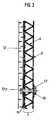
- a covering 12 made of natural stone or ceramicis glued onto a cover plate 2 by means of a mineral adhesive 6. If necessary, the covering 12 can additionally be secured by metallic bolts 13, so-called undercut anchors, which are anchored at one end 13a in the covering 12 and extend through the building board 1. A nut 14 is screwed onto the other end of the bolt 13.
- various types of cover layerscan be connected in a simple manner to the building board in the manner described above by gluing and / or screws and optionally rivets, the holes 3 in the cover plates 2 serving to anchor the adhesive or the screws or rivets.
- the coatingsare adapted to the respective purpose.
- the building boardscan also serve as supporting elements for large, prefabricated facade elements, which can be decorated, insulated and provided with pre-assembled window units in a sandwich construction at the factory.
- the prefabricated facade panelswhich can have a size of 2.5 x 6 - 10 m, then only need to be transported from the factory to the construction site and can be assembled there with little assembly effort to a fully functional outer wall on a corresponding supporting structure of the building .
- the relatively low weight and the inseparability of the building board according to the inventionplay an important role here.
Landscapes
- Engineering & Computer Science (AREA)
- Architecture (AREA)
- Civil Engineering (AREA)
- Structural Engineering (AREA)
- Finishing Walls (AREA)
Abstract
Description
Translated fromGermanDie Erfindung betrifft eine Bauplatte aus Metall als Tragelement für Wandplatten, Fassadenplatten und dgl..The invention relates to a building board made of metal as a supporting element for wall panels, facade panels and the like ..
Wandplatten, Fassadenplatten und dgl. bestehen im allgemeinen aus einem tragenden Element, welches ein- oder beidseitig mit einer Deckschicht versehen ist. Als Deckschicht kommt beispielsweise eine Putzschicht in Frage, die meist auf einer Zwischenschicht aufgebracht wird. Die Deckschicht kann jedoch auch ein Naturstein- oder Keramikbelag sein. An der anderen Seite der Bauplatte kann eine Dämmplatte angebracht sein, die zur Wärme- und/oder Schalldämmung dient. Diese Dämmplatte kann gegebenenfalls auch als Träger für eine weitere Putzschicht dienen. Eine solche, als Tragelement dienende Bauplatte soll möglichst biegesteif, von geringem Gewicht und billig herstellbar sein. Darüberhinaus soll sie jedoch eine einfache und sichere Verankerung der Deck- oder Dämmschichten ermöglichen. Wenn die Bauplatte zur Herstellung einer Fassadenplatte verwendet wird, muß sie außerdem feuchtigkeitsunempfindlich sein. Außerdem wird vielfach auch Unbrennbarkeit gefordert.Wall panels, facade panels and the like generally consist of a load-bearing element which is provided on one or both sides with a cover layer. For example, a plaster layer, which is usually applied to an intermediate layer, can be used as the top layer. However, the top layer can also be a natural stone or ceramic covering. On the other side of the building board, an insulation board can be attached, which is used for thermal and / or acoustic insulation. This insulation board can optionally also serve as a carrier for a further layer of plaster. Such a building board, which serves as a supporting element, should be as rigid as possible, light in weight and inexpensive to manufacture. In addition, however, it should enable simple and secure anchoring of the cover or insulation layers. If the building board is used to produce a facade panel, it must also be insensitive to moisture. In addition, incombustibility is often required.
Der Erfindung liegt daher die Aufgabe zugrunde, eine Bauplatte aus Metall zu schaffen, die leicht, stabil, unbrennbar, feuchtigkeitsunempfindlich, sowie kostengünstig herstellbar ist, und an der sich Beschichtungen durch Kleben und/oder Schrauben oder Nieten in einfacher Weise dauerhaft anbringen lassen.The invention is therefore based on the object of providing a building board made of metal which is light, stable, incombustible, insensitive to moisture and inexpensive to produce, and to which coatings can be permanently attached in a simple manner by adhesive bonding and / or screws or rivets.
Die Bauplatte aus Metall ist nach der Erfindung gekennzeichnet durch zwei parallel und in Abstand zueinander angeordnete, ebene Deckplatten aus Metallblech, von denen jede eine Vielzahl von Löchern aufweist, und ein dazwischen angeordnetes Aussteifungselement in Form eines zickzackförmig gebogenen Streckmetallgitters, welches entlang seiner Biegekanten mit der jeweils anliegenden Deckplatte verschweißt ist.The building board made of metal is characterized according to the invention by two parallel and spaced, flat cover plates made of sheet metal, of each of which has a plurality of holes, and a stiffening element arranged in between in the form of a zigzag-shaped expanded metal mesh, which is welded along its bending edges to the cover plate in each case.
Zur Herstellung der erfindungsgemäßen Bauplatte können Deckplatten aus verhältnismäßig dünnem Blech verwendet werden, da diese durch das Aussteifungselement in Form eines zickzackförmig gebogenen Streckmetallgitters und die Verschweißung mit diesem Streckmetallgitter insgesamt eine hohe Steifigkeit erhalten. Die in den Deckplatten vorgesehenen Löcher und auch die im Streckmetallgitter des Aussteifungselementes vorgesehenen Durchbrechungen verringern das Gesamtgewicht der Bauplatte ebenfalls. Da die gesamte Bauplatte aus Metall besteht, ist sie unbrennbar und bei entsprechendem Korrosionsschutz auch feuchtigkeitsunempfindlich. Sie kann auch kostengünstig gefertigt werden, da gelochte Bleche und Streckmetallgitter in großen Mengen für andere Zwecke hergestellt werden. Das zickzackförmige Biegen des Streckmetallgitters und die Verschweißung seiner Biegekanten mit den jeweils anliegenden Deckplatten sind einfache Arbeitsvorgänge, die ebenfalls zu einer kostengünstigen Herstellung der Bauplatte beitragen. Neben der Verringerung des Gewichtes haben die in den Deckplatten vorgesehenen Löcher aber auch eine weitere wichtige Funktion. Sie ermöglichen nämlich eine einfache und dauerhafte Befestigung von Beschichtungen an den Außenseiten der Deckplatten durch Kleben und/oder Schrauben. Beim Kleben wird die Haftfestigkeit dadurch unterstützt, daß der Kleber durch die Löcher bis zur Deckplatteninnenseite hineinquilt und sich dort etwas ausbreitet. Hierdurch erhält der Kleber an der Deckplatteninnenseite eine nagel- oder nietkopfähnliche Form, die zur sicheren, formschlüssigen Verankerung des Klebers beiträgt. Wenn anstelle des Klebers oder zusätzlich zu diesem selbstschneidende Schrauben verwendet werden, dann ermöglichen die in den Deckplatten vorgesehenen Löcher ein einfaches Einschrauben dieser selbstschneidenden Schrauben.Cover plates made of relatively thin sheet metal can be used to produce the building board according to the invention, since the reinforcement element in the form of a zigzag-shaped expanded metal lattice and the welding to this expanded metal lattice give it a high rigidity overall. The holes provided in the cover plates and also the openings provided in the expanded metal grid of the stiffening element also reduce the overall weight of the building board. Since the entire building board is made of metal, it is non-flammable and, with appropriate corrosion protection, also insensitive to moisture. It can also be manufactured inexpensively, since perforated sheets and expanded metal grids are produced in large quantities for other purposes. The zigzag-shaped bending of the expanded metal grid and the welding of its bending edges to the respective cover plates are simple work processes which also contribute to the cost-effective production of the building board. In addition to reducing the weight, the holes provided in the cover plates also have another important function. They allow simple and permanent attachment of coatings to the outer sides of the cover plates by gluing and / or screws. When gluing, the adhesive strength is supported by the fact that the glue quilts through the holes to the inside of the cover plate and spreads out a little there. This gives the glue a shape similar to a nail or rivet head on the inside of the cover plate, which contributes to the secure, form-fitting anchoring of the adhesive. If self-tapping screws are used instead of or in addition to the adhesive, then the holes provided in the cover plates make it easy to screw in these self-tapping screws.
Vorzugsweise bestehen die Deckplatten aus einem flachgewalzten Streckmetallgitter. Die Fertigung derartiger Platten aus flachgewalztem Streckmetall ist sehr wirtschaftlich, weil hierdurch die gewünschten Löcher geschaffen werden und gleichzeitig die Fläche der Deckplatte ohne Erzeugung von Abfällen vergrößert wird.The cover plates preferably consist of a flat-rolled expanded metal grid. The production of such plates from flat-rolled expanded metal is very economical because it creates the desired holes and at the same time increases the area of the cover plate without generating waste.
Weitere vorteilhafte Ausgestaltungen der Erfindung sind in den übrigen Unteransprüchen gekennzeichnet.Further advantageous embodiments of the invention are characterized in the remaining subclaims.
Die Erfindung ist in folgendem, anhand von in der Zeichnung dargestellten Ausführungsbeispielen näher erläutert. Es zeigen:
- Figur 1
- einen Querschnitt der neuen Bauplatte,
Figur 2 und 3- Querschnitte der Bauplatte mit daran angebrachten verschiedenartigen Deckschichten.
- Figure 1
- a cross section of the new building board,
- Figures 2 and 3
- Cross sections of the building board with various cover layers attached to it.
Die Bauplatte 1 aus Metall besteht zunächst aus zwei ebenen, parallel und in größerem Abstand zueinander angeordneten Deckplatten 2. Jede der Deckplatten 2 ist mit einer Vielzahl von Löchern 3 versehen. Als Deckplatten werden vorzugsweise flachgewalzte Streckmetallgitter verwendet. Bei der Herstellung des Streckmetallgitters für die Deckplatten 2 werden die Einschnitte in das Blech so gewählt, daß die nach dem Flachwalzen des Streckmetallgitters verbleibenden Löcher 3 annähernd rund sind. Die runde Form wird bevorzugt, da sich dann in die Löcher 3 selbstschneidende Schrauben einschrauben lassen. Zwischen den beiden Deckplatten 2 ist ein Aussteifungselement 4 angeordnet. Dieses Aussteifungselement besteht aus einem zickzackförmigen Streckmetallgitter. Das Streckmetallgitter 4 ist entlang seiner Biegekanten 4a mit der jeweils anliegenden Deckplatte 2 verschweißt. Die Verschweißung kann mittels Laser, Rollenschweißtechnik oder einer ähnlichen Schweißtechnik erfolgen. Das Streckmetallgitter 4 wird zweckmäßig so zickzackförmig gebogen, daß zwei aneinandergrenzende Abschnitte 4b jeweils einen Winkel α von etwa 60° miteinander einschließen. Die Löcher 3 in den Deckplatten 2 sollten einen Durchmesser aufweisen, welcher dem Durchmesser der zur Befestigung von Deckschichten verwendeten Schrauben angepaßt ist. Ein Durchmesser von etwa 4 - 6 mm ist zweckmäßig.The metal building plate 1 initially consists of two flat, parallel and spaced-
Anstelle von flachgewalzten Streckmetallgittern können für die Deckplatten 2 gegebenenfalls auch Lochbleche verwendet werden, jedoch haben derartige Lochbleche den Nachteil, daß bei der Erzeugung der Löcher Abfälle entstehen.Instead of flat-rolled expanded metal grids, perforated plates can also be used for the
Die Bauplatte 1 kann aus verschiedenen geeigneten Materialien bestehen, wie z.B. Stahl, rostfreiem Stahl, Aluminium, oder sonstigem Metall. Wenn die Deckplatten 2 und das Aussteifungselement 4 aus Stahl bestehen, sollten sie vorzugsweise mit einer Korrosionsschutzschicht versehen sein, die zweckmäßig galvanisch aufgebracht ist.The building board 1 can be made of various suitable materials, such as steel, stainless steel, aluminum, or other metal. If the
Anhand der Figuren 2 und 3 soll nun erläutert werden, wie sich an der neuen Bauplatte 1 verschiedene Deckschichten in einfacher Weise dauerhaft anbringen lassen. Bei dem in Figur 2 dargestellten Ausführungsbeispiel ist auf die eine (linke) Deckplatte 2 eine Dämmstoffschicht 5 aus mineralischen Stoffen mittels eines zweckmäßig mineralischen Klebers 6 aufgeklebt. Wie man aus der Zeichnung erkennen kann, ist der Kleber 6 durch die Löcher 3 der Deckplatte 2 hindurchgequollen und bildet an der Deckplatteninnenseite 2a Verdickungen 6a, ähnlich wie ein Nietkopf oder ein Nagelkopf. Diese Verdickungen 6a sorgen zusätzlich zu der Adhäsionswirkung des Klebers auch noch für eine formschlüssige Verankerung desselben. Die Dämmstoffschicht kann zusätzlich auch noch durch selbstschneidende Schrauben 7, die in einige der Löcher 3 eingeschraubt sind, gesichert werden. An der Außenseite der Dämmstoffschicht 5 ist eine Putzschicht 8 aufgebracht. Mit der anderen (rechten) Deckplatte 2 der Bauplatte 1 ist eine Trägerplatte 9 mittels selbstschneidender Schrauben 10, die in entsprechende Löcher 3 eingeschraubt sind, verbunden. Die Trägerplatte 9 kann beispielsweise aus einem mit einem geschäumten organischen Bindemittel gebundenen Blähglasgranulat bestehen. Ein Verfahren zur Herstellung einer derartigen Trägerplatte ist in der EP 290 881 A2 beschrieben. Auf der Trägerplatte 9 ist schließlich eine Putzschicht 11 aufgebracht. Gegebenenfalls kann die Putzschicht 11 auch unmittelbar auf der Deckplatte 2 aufgetragen sein, wobei dann Teile der Putzschicht die Löcher 3 durchdringen und dort gut verankert werden. Eine derartige Sandwich-Konstruktion, die aus den vorgenannten Baustoffen besteht, ist als Ganzes unbrennbar.On the basis of Figures 2 and 3 will now be explained how different cover layers can be permanently attached to the new building board 1 in a simple manner. In the exemplary embodiment shown in FIG. 2, an
Ähnliches gilt auch für das in Figur 3 dargestellte Ausführungsbeispiel. Hier ist ein Belag 12 aus Naturstein oder Keramik mittels eines mineralischen Klebers 6 auf die eine Deckplatte 2 aufgeklebt. Gegebenenfalls kann der Belag 12 noch zusätzlich durch metallische Bolzen 13, sogenannte Hinterschnittanker, gesichert sein, die mit ihrem einen Ende 13a in dem Belag 12 verankert sind und sich durch die Bauplatte 1 hindurcherstrecken. Auf das andere Ende des Bolzens 13 ist eine Mutter 14 aufgeschraubt.The same applies to the embodiment shown in Figure 3. Here, a covering 12 made of natural stone or ceramic is glued onto a
Grundsätzlich können Deckschichten verschiedenster Art in einfacher Weise mit der Bauplatte in der vorherbeschriebenen Weise durch Kleben und/oder Schrauben sowie gegebenenfalls Nieten verbunden werden, wobei die Löcher 3 in den Deckplatten 2 zur Verankerung des Klebers bzw. der Schrauben oder Nieten dienen. Die Beschichtungen sind dem jeweiligen Zweck angepaßt. Bei entsprechender Dicke können die Bauplatten auch als Tragelemente für großflächige, vorgefertigte Fassadenelemente dienen, die in Sandwichbauweise fabrikseitig fertig dekoriert, gedämmt und mit vormontierten Fenstereinheiten versehen werden können. Die so vorgefertigten Fassadenplatten, welche eine Größe von 2,5 x 6 - 10 m haben können, brauchen dann von der Fabrik nur noch zur Baustelle transportiert werden und können dort mit geringem Montageaufwand zu einer voll funktionsfähigen Außenwand an einer entsprechenden Tragkonstruktion des Gebäudes montiert werden. Das verhältnismäßig geringe Gewicht und die Untrennbarkeit der erfindungsgemäßen Bauplatte spielen hierbei eine wichtige Rolle.Basically, various types of cover layers can be connected in a simple manner to the building board in the manner described above by gluing and / or screws and optionally rivets, the
Claims (9)
Translated fromGermanApplications Claiming Priority (2)
| Application Number | Priority Date | Filing Date | Title |
|---|---|---|---|
| DE19519028 | 1995-05-24 | ||
| DE19519028 | 1995-05-24 |
Publications (1)
| Publication Number | Publication Date |
|---|---|
| EP0744510A1true EP0744510A1 (en) | 1996-11-27 |
Family
ID=7762746
Family Applications (1)
| Application Number | Title | Priority Date | Filing Date |
|---|---|---|---|
| EP96105668AWithdrawnEP0744510A1 (en) | 1995-05-24 | 1996-04-11 | Structural panel of metal |
Country Status (2)
| Country | Link |
|---|---|
| EP (1) | EP0744510A1 (en) |
| CA (1) | CA2175398A1 (en) |
Cited By (5)
| Publication number | Priority date | Publication date | Assignee | Title |
|---|---|---|---|---|
| DE19936990A1 (en)* | 1999-07-30 | 2001-02-01 | Guenther Jelonnek | Wall and ceiling element comprises single elements joined by special-purpose profiles via spacers using step-flanged profile ends for their positive abutted connection. |
| EP1074670A2 (en) | 1999-07-30 | 2001-02-07 | Günther Jelonnek | Building construction |
| US6331406B1 (en) | 1997-03-31 | 2001-12-18 | The John Hopkins University School Of Medicine | Human enbryonic germ cell and methods of use |
| EP1369542A1 (en)* | 2002-06-05 | 2003-12-10 | Corus Bausysteme GmbH | Sheet-metal cladding panel and process for manufacturing the same |
| WO2007141382A1 (en)* | 2006-06-02 | 2007-12-13 | Rautaruukki Oyj | Outer wall of building and metal honeycomb structure for use therein |
Citations (9)
| Publication number | Priority date | Publication date | Assignee | Title |
|---|---|---|---|---|
| FR544758A (en)* | 1921-12-21 | 1922-09-29 | Metal panel | |
| US1701304A (en)* | 1926-08-12 | 1929-02-05 | Jr Walter Clyde Jones | Steel lumber |
| FR1024889A (en)* | 1950-09-25 | 1953-04-08 | Improvements to hollow composite panels | |
| FR1440387A (en)* | 1965-07-07 | 1966-05-27 | Siemag Siegener Masch Bau | Construction panel |
| DE1559507A1 (en)* | 1965-12-03 | 1969-11-06 | Bauakademie Ddr | Double-shell lightweight panel |
| DE1609661A1 (en)* | 1966-02-11 | 1970-05-06 | Hagenburg Otto Heinrich Graf | Flat or curved surface structure, especially made of glass fiber reinforced plastic |
| GB1589715A (en)* | 1977-10-07 | 1981-05-20 | Rigby F A | Structural panels |
| AT389070B (en)* | 1987-08-06 | 1989-10-10 | Guerth Werner Ing | Method and device for producing a welded sandwich panel produced from metal sheets lying one on top of the other |
| DE3834501A1 (en)* | 1988-10-11 | 1990-04-12 | Martin Holzlehner | Panel-type structural element |
- 1996
- 1996-04-11EPEP96105668Apatent/EP0744510A1/ennot_activeWithdrawn
- 1996-04-30CACA 2175398patent/CA2175398A1/ennot_activeAbandoned
Patent Citations (9)
| Publication number | Priority date | Publication date | Assignee | Title |
|---|---|---|---|---|
| FR544758A (en)* | 1921-12-21 | 1922-09-29 | Metal panel | |
| US1701304A (en)* | 1926-08-12 | 1929-02-05 | Jr Walter Clyde Jones | Steel lumber |
| FR1024889A (en)* | 1950-09-25 | 1953-04-08 | Improvements to hollow composite panels | |
| FR1440387A (en)* | 1965-07-07 | 1966-05-27 | Siemag Siegener Masch Bau | Construction panel |
| DE1559507A1 (en)* | 1965-12-03 | 1969-11-06 | Bauakademie Ddr | Double-shell lightweight panel |
| DE1609661A1 (en)* | 1966-02-11 | 1970-05-06 | Hagenburg Otto Heinrich Graf | Flat or curved surface structure, especially made of glass fiber reinforced plastic |
| GB1589715A (en)* | 1977-10-07 | 1981-05-20 | Rigby F A | Structural panels |
| AT389070B (en)* | 1987-08-06 | 1989-10-10 | Guerth Werner Ing | Method and device for producing a welded sandwich panel produced from metal sheets lying one on top of the other |
| DE3834501A1 (en)* | 1988-10-11 | 1990-04-12 | Martin Holzlehner | Panel-type structural element |
Cited By (6)
| Publication number | Priority date | Publication date | Assignee | Title |
|---|---|---|---|---|
| US6331406B1 (en) | 1997-03-31 | 2001-12-18 | The John Hopkins University School Of Medicine | Human enbryonic germ cell and methods of use |
| DE19936990A1 (en)* | 1999-07-30 | 2001-02-01 | Guenther Jelonnek | Wall and ceiling element comprises single elements joined by special-purpose profiles via spacers using step-flanged profile ends for their positive abutted connection. |
| EP1074670A2 (en) | 1999-07-30 | 2001-02-07 | Günther Jelonnek | Building construction |
| EP1369542A1 (en)* | 2002-06-05 | 2003-12-10 | Corus Bausysteme GmbH | Sheet-metal cladding panel and process for manufacturing the same |
| WO2007141382A1 (en)* | 2006-06-02 | 2007-12-13 | Rautaruukki Oyj | Outer wall of building and metal honeycomb structure for use therein |
| RU2426843C2 (en)* | 2006-06-02 | 2011-08-20 | РАУТАРУУККИ ОУДж. | External wall of building |
Also Published As
| Publication number | Publication date |
|---|---|
| CA2175398A1 (en) | 1996-11-25 |
Similar Documents
| Publication | Publication Date | Title |
|---|---|---|
| EP0835356B1 (en) | Covering material which can be plastically deformed by hand | |
| EP0023618B1 (en) | Sound absorbing building board and process for its manufacture | |
| WO2002044497A1 (en) | Method for fixing insulating boards and corresponding dowel | |
| DE19922592A1 (en) | Insulating element of mineral wool, especially for insulating area above roof rafters, comprises one-piece panel element with insulating section and load relieving web with high compression resistance | |
| EP0744510A1 (en) | Structural panel of metal | |
| DE19823139C2 (en) | Soundproofing interior or exterior wall cladding | |
| EP0085863A1 (en) | Sound-absorbing panels | |
| DE3004615C2 (en) | Light steel roof | |
| DE20320425U1 (en) | Hybrid building panel comprises transparent sheet of glass or plastic and corrugated metal panel which are bolted or glued together at points where troughs in metal panel meet transparent sheet | |
| EP0406991A1 (en) | Facing panel | |
| EP0578230B1 (en) | Large-size ceramic slab to receive metallic fastening means | |
| EP0044467A1 (en) | Profiled building element, building component for partitioning and delimitation of spaces composed of these elements and method of making these elements | |
| DE3532023C2 (en) | ||
| WO1999018301A1 (en) | Gable or hip roof | |
| DE2325281A1 (en) | METAL SUPPORT ELEMENT FOR STRUCTURAL CEILINGS AND BUILDING CEILING FORMED FROM THIS METAL SUPPORT ELEMENT AND A CONCRETE LAYER | |
| DE3203314A1 (en) | Roof structure | |
| DE10315604B3 (en) | Hybrid building panel comprises transparent sheet of glass or plastic and corrugated metal panel which are bolted or glued together at points where troughs in metal panel meet transparent sheet | |
| EP3926117B1 (en) | Thermal insulation composite system, facade with the thermal insulation composite systemand method for erecting the same | |
| DE4405748A1 (en) | Composite panel, in particular for work in roof interiors | |
| DE2224232A1 (en) | PREFABRICATED PANEL-SHAPED COMPONENT FOR FLOOR AND / OR ROOF CEILINGS | |
| AT396805B (en) | Structural element | |
| AT405955B (en) | Load-bearing element for the production of load-bearing structures, and load-bearing structure produced using such load-bearing elements | |
| DE2719411C2 (en) | Heat and sound insulation mat | |
| DE202004001602U1 (en) | Profiled panel with longitudinally extended top surfaces or outer sides and two sides or side edges is designed in manner in which outer side has one, two or three convexities and these occupy larger part of surface | |
| DE1484240A1 (en) | Construction element for civil engineering |
Legal Events
| Date | Code | Title | Description |
|---|---|---|---|
| PUAI | Public reference made under article 153(3) epc to a published international application that has entered the european phase | Free format text:ORIGINAL CODE: 0009012 | |
| AK | Designated contracting states | Kind code of ref document:A1 Designated state(s):AT BE CH DE DK ES FI FR GB GR IT LI LU NL SE | |
| AX | Request for extension of the european patent | Free format text:LT PAYMENT 960411;LV PAYMENT 960411;SI PAYMENT 960411 | |
| STAA | Information on the status of an ep patent application or granted ep patent | Free format text:STATUS: THE APPLICATION IS DEEMED TO BE WITHDRAWN | |
| 18D | Application deemed to be withdrawn | Effective date:19970528 |