EP0743811B1 - Direct current arc plasma torch, specially conceived for the obtention of a chemical body by decomposition of a plasma gas - Google Patents
Direct current arc plasma torch, specially conceived for the obtention of a chemical body by decomposition of a plasma gasDownload PDFInfo
- Publication number
- EP0743811B1 EP0743811B1EP96400770AEP96400770AEP0743811B1EP 0743811 B1EP0743811 B1EP 0743811B1EP 96400770 AEP96400770 AEP 96400770AEP 96400770 AEP96400770 AEP 96400770AEP 0743811 B1EP0743811 B1EP 0743811B1
- Authority
- EP
- European Patent Office
- Prior art keywords
- plasma
- electrode
- gas
- tubular
- plasma torch
- Prior art date
- Legal status (The legal status is an assumption and is not a legal conclusion. Google has not performed a legal analysis and makes no representation as to the accuracy of the status listed.)
- Expired - Lifetime
Links
- 239000000126substanceSubstances0.000titleclaimsdescription8
- 238000000354decomposition reactionMethods0.000titledescription14
- 239000007789gasSubstances0.000claimsdescription65
- 238000002347injectionMethods0.000claimsdescription56
- 239000007924injectionSubstances0.000claimsdescription56
- 238000007664blowingMethods0.000claimsdescription23
- 239000012530fluidSubstances0.000claimsdescription16
- 230000009471actionEffects0.000claimsdescription11
- 230000004888barrier functionEffects0.000claimsdescription11
- 238000006243chemical reactionMethods0.000claimsdescription11
- 238000010891electric arcMethods0.000claimsdescription11
- 229910052739hydrogenInorganic materials0.000claimsdescription9
- 239000001257hydrogenSubstances0.000claimsdescription9
- 238000004891communicationMethods0.000claimsdescription8
- 238000010791quenchingMethods0.000claimsdescription8
- 230000000171quenching effectEffects0.000claimsdescription8
- UFHFLCQGNIYNRP-UHFFFAOYSA-NHydrogenChemical compound[H][H]UFHFLCQGNIYNRP-UHFFFAOYSA-N0.000claimsdescription4
- 125000004435hydrogen atomChemical group[H]*0.000claims1
- 235000010599Verbascum thapsusNutrition0.000description43
- 239000002245particleSubstances0.000description12
- 150000002500ionsChemical class0.000description9
- 239000000463materialSubstances0.000description7
- 241001080024TellesSpecies0.000description6
- 244000178289Verbascum thapsusSpecies0.000description5
- 230000015572biosynthetic processEffects0.000description4
- 150000001875compoundsChemical class0.000description4
- 150000002431hydrogenChemical class0.000description4
- -1sulfur ionsChemical class0.000description4
- 230000006378damageEffects0.000description3
- 239000000203mixtureSubstances0.000description3
- 239000011593sulfurSubstances0.000description3
- 229910052717sulfurInorganic materials0.000description3
- 208000031968CadaverDiseases0.000description2
- RYGMFSIKBFXOCR-UHFFFAOYSA-NCopperChemical compound[Cu]RYGMFSIKBFXOCR-UHFFFAOYSA-N0.000description2
- NINIDFKCEFEMDL-UHFFFAOYSA-NSulfurChemical compound[S]NINIDFKCEFEMDL-UHFFFAOYSA-N0.000description2
- 238000001816coolingMethods0.000description2
- 230000000694effectsEffects0.000description2
- 230000003628erosive effectEffects0.000description2
- 230000003993interactionEffects0.000description2
- 238000004519manufacturing processMethods0.000description2
- 240000008042Zea maysSpecies0.000description1
- CZBGCSZGIMINPA-UHFFFAOYSA-N[Rh].[W]Chemical compound[Rh].[W]CZBGCSZGIMINPA-UHFFFAOYSA-N0.000description1
- 239000011248coating agentSubstances0.000description1
- 238000000576coating methodMethods0.000description1
- 238000010276constructionMethods0.000description1
- 239000012809cooling fluidSubstances0.000description1
- 229910052802copperInorganic materials0.000description1
- 239000010949copperSubstances0.000description1
- 229940082150encoreDrugs0.000description1
- 238000005259measurementMethods0.000description1
- 238000005457optimizationMethods0.000description1
- 230000009467reductionEffects0.000description1
- 230000007704transitionEffects0.000description1
- WFKWXMTUELFFGS-UHFFFAOYSA-NtungstenChemical compound[W]WFKWXMTUELFFGS-UHFFFAOYSA-N0.000description1
- 229910052721tungstenInorganic materials0.000description1
- 239000010937tungstenSubstances0.000description1
Images


Classifications
- H—ELECTRICITY
- H05—ELECTRIC TECHNIQUES NOT OTHERWISE PROVIDED FOR
- H05H—PLASMA TECHNIQUE; PRODUCTION OF ACCELERATED ELECTRICALLY-CHARGED PARTICLES OR OF NEUTRONS; PRODUCTION OR ACCELERATION OF NEUTRAL MOLECULAR OR ATOMIC BEAMS
- H05H1/00—Generating plasma; Handling plasma
- H05H1/24—Generating plasma
- H05H1/26—Plasma torches
- H05H1/32—Plasma torches using an arc
- H05H1/34—Details, e.g. electrodes, nozzles
- H05H1/341—Arrangements for providing coaxial protecting fluids
- H—ELECTRICITY
- H05—ELECTRIC TECHNIQUES NOT OTHERWISE PROVIDED FOR
- H05H—PLASMA TECHNIQUE; PRODUCTION OF ACCELERATED ELECTRICALLY-CHARGED PARTICLES OR OF NEUTRONS; PRODUCTION OR ACCELERATION OF NEUTRAL MOLECULAR OR ATOMIC BEAMS
- H05H1/00—Generating plasma; Handling plasma
- H05H1/24—Generating plasma
- H05H1/26—Plasma torches
- H05H1/32—Plasma torches using an arc
- H05H1/34—Details, e.g. electrodes, nozzles
- H05H1/3468—Vortex generators
- H—ELECTRICITY
- H05—ELECTRIC TECHNIQUES NOT OTHERWISE PROVIDED FOR
- H05H—PLASMA TECHNIQUE; PRODUCTION OF ACCELERATED ELECTRICALLY-CHARGED PARTICLES OR OF NEUTRONS; PRODUCTION OR ACCELERATION OF NEUTRAL MOLECULAR OR ATOMIC BEAMS
- H05H1/00—Generating plasma; Handling plasma
- H05H1/24—Generating plasma
- H05H1/26—Plasma torches
- H05H1/32—Plasma torches using an arc
- H05H1/34—Details, e.g. electrodes, nozzles
- H05H1/3431—Coaxial cylindrical electrodes
- H—ELECTRICITY
- H05—ELECTRIC TECHNIQUES NOT OTHERWISE PROVIDED FOR
- H05H—PLASMA TECHNIQUE; PRODUCTION OF ACCELERATED ELECTRICALLY-CHARGED PARTICLES OR OF NEUTRONS; PRODUCTION OR ACCELERATION OF NEUTRAL MOLECULAR OR ATOMIC BEAMS
- H05H1/00—Generating plasma; Handling plasma
- H05H1/24—Generating plasma
- H05H1/26—Plasma torches
- H05H1/32—Plasma torches using an arc
- H05H1/34—Details, e.g. electrodes, nozzles
- H05H1/40—Details, e.g. electrodes, nozzles using applied magnetic fields, e.g. for focusing or rotating the arc
Definitions
- the present inventionrelates to a plasma arc torch direct current, particularly intended for obtaining of a chemical body by decomposition of a plasma gas.
- a DC arc plasma torchcomprising two coaxial tubular electrodes arranged in extension of each other, on either side of a chamber, into which a stream of plasma gas is injected, for example air.
- Each of said electrodesis open on the side of said injection chamber, while one of which is further open at its far end of said injection chamber.
- the arc between said electrodescrosses said injection chamber and ionizes the plasma gas introduced in this one.
- Said archhangs by its end feet respectively to the internal face of said electrodes and ionized gas plasma, high pressure (pressure atmospheric at around 5 bar) and at very high temperature (several thousand ° C), crosses the open electrode at both ends and flows out of said torch at through the opening of this last electrode away from said injection chamber.
- the flow of plasma coming out of said torchcomprises ions of the elements composing said gas, as a result of the action of the electric arc on said gas plasmagen.
- the plasma gasis hydrogen sulfurous
- the plasma flowcontains ions hydrogen and sulfur ions. Therefore, if we submit said plasma flow at thermal quenching it is possible to collect the elements of the plasma gas.
- sulfurous hydrogenas plasma gas, then quenching the plasma, allow therefore to collect sulfur, on the one hand, and hydrogen, on the other hand.
- a torch of the type described abovecan serve as a reactor for the decomposition of gaseous compounds plasmagenics.
- the object of the present inventionis to remedy these drawbacks. It relates to a plasma arc torch of long service life, particularly suitable to be used as a thermochemical decomposition reactor, operating with good energy efficiency and allowing obtaining high purity decomposition products.
- the plasma leaving the torch conforms to the present inventionis particularly pure.
- said fluid barrierforms a sheath protecting the internal surface of the first electrode against the action erosion of plasma ions. We therefore also improve the lifetime of this electrode.
- said first tubular partis integral of the first electrode, and it can even form one single piece with the latter, so as to appear as an elongated portion of said electrode.
- said first tubular partplays no role electric role vis-à-vis the arc in established regime, it can be dimensioned in volume, in diameter and length so that aerothermal conditions (pressure, temperature) optimize the chemical yield and, therefore, energy yield.
- aerothermal conditionspressure, temperature
- said first means for forming said fluid barrierare constituted by first means of blowing causing, on the internal wall of said first electrode, a first tubular flow of a gas to pressure at least approximately equal to that of plasma and at a temperature much lower than that of said plasma, said first fluid tubular flow surrounding said flow of plasma and flowing in the same direction as it.
- a flow of central plasma containing gas decomposition ions plasma and an annular flow formed by the gas blowing and surrounding said central flow of the plasmais at very high temperature (several thousands of ° C) and at high pressure (atmospheric pressure at around 5 bars).
- the flow blowing ringcan be at low temperature (by room temperature) and at a pressure of the order of that of plasma.
- the central flow and the annular flowhave very viscosities different, prohibiting their mixing. The particles of electrodes, torn off by the arc, cannot therefore pass from the annular flow of the blowing gas at the flow of central plasma, surrounded by this annular flow.
- the blown gasmay, for example, be hydrogen.
- said first electrodehas a larger diameter that said first tubular part and that said first blowing means are arranged between said first tubular part and said first electrode.
- This blowing gascan be blown on the internal wall of said first electrode, parallel to the axis of this last.
- the gas from said first tubular flowcan be blown inside said first electrode, tangentially to the inner wall of the latter, similar to what is generally practiced for the so-called vortex injection of plasma gas into the injection chamber.
- Such tangential blowing meansmay have an inner crown and a crown coaxial outer, providing a room between them annular supplied with blowing gas through said outer crown, while the central opening of said inner crown forms at least approximately an extension of the internal surface of said first electrode and that said central crown opening inner is connected to said annular chamber by at at least one orifice tangential to said central opening.
- said second electrode and its elements partnersmay have the same features as those mentioned above about the first electrode.
- the plasma torch according to the present inventionincludes means for moving the feet arcs, such as those described above.
- means for moving the feet arcssuch as those described above.
- such meansdo not have to act on the first and second tubular parts, but only on the electrodes.
- meansare provided, which can be, known manner, of the type with electric discharge produced between both electrodes or short-circuit type, thanks, by example, when using an auxiliary electrode start-up.
- said arc electric between the parts of said neighboring electrodes of said injection chamber(said first and second tubular parts), then to extend said arc under the effect of the vortex injection of plasma gas, until that the feet of said arc are hooked to the surface internal of said end portions of the electrodes, remote of said injection chamber (electrodes properly say).
- said means for injecting the plasma gas in said chamberallow to inject it in vortices in planes perpendicular to the common axis electrodes.
- These means of injectionmay include (see US-A-5,262,616 mentioned above) a piece of coaxial revolution to said electrodes and defining with these and their supports said injection chamber. Of transverse holes are provided in the room to allow injection of plasma gas from a supply circuit, in the bedroom.
- the temperatures plasma damage to the torch outletsmay exceed 5000 ° C. Also, it is essential to plan cooling circuits for the electrodes, such as this is moreover usual for plasma torches.
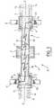
- FIG. 1shows, in very schematic longitudinal section, a first example of a plasma torch in accordance with this invention, to illustrate the inventive principle of this one.
- Figure 2illustrates the section, along line II-II of the Figure 1, the fluid flow at the outlet of the torch to plasma.
- Figure 3shows, also in very longitudinal section schematic, a second example of a plasma torch conforming to the present invention.
- Figure 4is a simplified longitudinal section of a mode of practical realization of the plasma torch of the figure 1.
- Figure 5is a cross section along the line V-V in Figure 4.
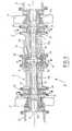
- Figure 6is a simplified longitudinal section of a mode of practical realization of the plasma torch of the figure 3.
- the exemplary embodiment I of the plasma torchin accordance with the present invention and shown very schematically in FIG. 1, has an anode 1 and a part cathodic 2, tubular and coaxial, arranged in extension from each other along an X-X axis, on both sides other of a chamber 3 into which is injected, any in known manner, a plasma gas (arrows P).
- Anode 1 and the cathode partare cooled in any suitable way and known, but not shown.
- the anode 1is elongated along the axis X-X and comprises, at its end arranged opposite the injection chamber 3, an opening 4 connecting the interior of said anode 1 with said injection chamber 3. On the other hand, at its end opposite to the injection chamber 3, the anode 1 is closed by a bottom 5.
- the cathode part 2comprises, at its end remote from the injection chamber 3, a cathode 2A open towards the outside by an opening 6.
- the cathode 2Ais extended, in the direction of the injection chamber 3, by a part tubular 2B forming an integral part of said cathode 2A.
- the cathode 2Ahas a diameter D greater than the diameter d of the tubular part 2B and a shoulder 7 connects the cathode 2A and the tubular part 2B.
- orifices 8are provided, distributed around the axis XX and with an axis at least substantially parallel thereto.
- the tubular part 2Bhas an opening 9 putting the interior of the cathode part 2 into communication with said injection chamber 3.
- an electric arc 10crosses the chamber injection 3 and the tubular part 2B and hooks, by its end legs 10a and 10c, respectively on the internal surface of anode 1 (near bottom 5 opposite to the injection chamber 3) and to that of the cathode 2A.
- Electromagnetic coils 11 and 12intended for the rotation of the feet 10a and 10c of the arc 10 around the axis X-X, respectively surround the anode 1 (in the vicinity of the bottom 5) and cathode 2A.
- the stream of plasma gas P entering the tubular part 2Bis transformed, in the latter and under the action of the arc 10, in a plasma flow 13, leaving through opening 6 after passing through the cathode 2A.
- the tubular part 2Btherefore forms a reaction chamber in which the plasma gas is transformed into a plasma, at high pressure and at very high temperature, comprising ions of the components of said plasma gas. It's obvious that the tubular part 2B can be dimensioned to optimize energy efficiency.
- a gas Gfor example hydrogen
- a gas Gfor example hydrogen
- the particles of matter from the cathode 2Awhich are torn off from the inner surface thereof by the arc foot 10c, not only can not mix to the plasma flow 13 but still are evacuated by the annular gas stream 14. They cannot therefore pollute plasma flow 13.
- particles of material from anode 1, which are torn off at this by the arc foot 10aremain in the anode 1 (this which is obtained from the fact that the anode 1 is long and that the arch 10a is in the vicinity of the bottom 5), the flow plasma 13, comprising ions of the gas components is particularly pure.
- a quenching device(not shown, but of any type known) allows the annular gas stream 14 to be separated from the plasma flow 13 and then extract the components chemicals contained in the form of ions in said flow plasma 13.
- the anode part 1 ′comprises, at its end remote from the injection chamber 3, an anode 1'A open towards the outside by an opening 15.
- the anode 1'Ais extended, in the direction of the injection chamber 3, by a tubular piece 1'B forming an integral part of said anode.
- the anode 1'Ahas a diameter D greater than the diameter d of the tubular piece 1'B and a shoulder 16 connects the anode 1'A and the tubular piece 1'B.
- orifices 17are provided, distributed around the axis XX and with an axis at least substantially parallel thereto.
- the tubular part 1'Bhas an opening 18 putting the interior of the anode part 1 'into communication with the injection chamber 3.
- the electric arc 10crosses the chamber injection 3 and the tubular parts 1'B and 2B and hooks, by its feet 10a and 10c, respectively on the surface internal of anode 1'A and cathode 2A.
- the plasma gas injected into chamber 3divides in two streams, one of which enters the tubular part 1'B and the other in the tubular part 2B.
- said plasma gas streamstransform into two opposite plasma flows 13 and 19, leaving through openings 6 and 15, after crossing cathode 2A and anode 1'A respectively.
- Rooms 1'B AND 2B tubulartherefore form reaction chambers in which the plasma gas is transformed into plasma.
- FIG 4there is shown an embodiment practice of Example I in Figure 1.
- the tubular body 30 of the plasma torch, surrounding the anode 1 and the cathode part 2is constituted (at simplicity of construction) of a plurality of sections 30A, 30B, 30C ... coaxial with each other and with said electrodes and tightly assembled one at the end of the other.
- connection means 31are provided for sealingly open open end 6, remote from the injection chamber 3, from the cathode 2A to a device quenching (not shown).
- Conduits 32 and 33are respectively provided around the anode 1 and the workpiece cathodic 2 for the circulation of a cooling fluid of these.
- the means 34 for injecting the plasma gas into the chamber 3are of the vortex injection type, such than those described in US-A-5,262,616. They are made up by a part of revolution, coaxial with the X-X axis and include an annular groove 35, supplied with plasma gas (arrows P) and connected to the injection chamber 3 by transverse holes 36.
- a short-circuit ignition device 37is provided, known type with auxiliary starting electrode 38.
- the arc 10can be struck between the parts of the anode 1 and of tubular part 2B, adjacent to the injection chamber 3, then stretched out under the effect of the vortex injection plasma gas, until feet 10a and 10b of said arc are attached to the internal surface of anode 1 near the bottom 5 and that of the cathode 2A, in the field coils 11 and 12.
- the torch of Figure 4(see also Figure 5) has a section 30E constituting the device S for tangential blowing of the fluid tubular flow 14, surrounding the flow of plasma 13.
- the blowing device Scomprises an inner ring 39 (crossed by the cooling conduits 33) and an outer ring 40 coaxial with the axis XX , forming between them an annular chamber 41, supplied with blowing gas (see arrows G) through said outer ring 40.
- the central opening 42 of the inner ring 39has the diameter D and forms at least approximately an extension of the internal surface of cathode 2A. This central opening 42 therefore forms the transition between the internal surface of the tubular part 2B of diameter d and the internal surface of the cathode 2A of diameter D. It is connected to the annular chamber 41 by orifices 43, tangential to its internal surface .
- Example II of the plasma torchin the practical embodiment of Example II of the plasma torch, according to the present invention and shown in section in Figure 6, we have, compared to the mode of practical embodiment of Figures 4 and 5, replaced the anode 1 by the anode part 1 ', similar (but opposite along from the X-X axis) to the cathode part 2.
- the part anode 1 ′comprises the anode 1'A and the tubular part 1'B, connected by a tangential blowing device S '.
- the anode 1'A, the tubular part 1'B and the device blowing S ′are respectively identical to cathode 2A, to the tubular part 2B and to the blowing device S.
- Des connection means 44are provided for connecting so seals the open end 15 away from the chamber injection 3, from the 1'A anode to a quenching device (not represented).
Landscapes
- Physics & Mathematics (AREA)
- Engineering & Computer Science (AREA)
- Plasma & Fusion (AREA)
- Spectroscopy & Molecular Physics (AREA)
- Plasma Technology (AREA)
- Discharge Heating (AREA)
Description
Translated fromFrenchLa présente invention concerne une torche à plasma d'arc àcourant continu, particulièrement destinée à l'obtentiond'un corps chimique par décomposition d'un gaz plasmagène.The present invention relates to a plasma arc torchdirect current, particularly intended for obtainingof a chemical body by decomposition of a plasma gas.
Par exemple, par le brevet américain US-A-5 262 616, onconnaít déjà une torche à plasma d'arc à courant continucomportant deux électrodes tubulaires coaxiales disposées enprolongement l'une de l'autre, de part et d'autre d'unechambre, dans laquelle est injecté un courant de gaz plasmagène,par exemple de l'air. Chacune desdites électrodes estouverte du côté de ladite chambre d'injection, tandis quel'une d'elles est de plus ouverte à son extrémité éloignéede ladite chambre d'injection.For example, by US patent US-A-5,262,616, wealready know a DC arc plasma torchcomprising two coaxial tubular electrodes arranged inextension of each other, on either side of achamber, into which a stream of plasma gas is injected,for example air. Each of said electrodes isopen on the side of said injection chamber, whileone of which is further open at its far endof said injection chamber.
Ainsi, l'arc entre lesdites électrodes traverse laditechambre d'injection et ionise le gaz plasmagène introduitdans celle-ci. Ledit arc s'accroche par ses pieds d'extrémitérespectivement à la face interne desdites électrodes etle plasma de gaz ionisé, à haute pression (de la pressionatmosphérique à environ 5 bars) et à très haute température(plusieurs milliers de °C), traverse l'électrode ouverte àses deux extrémités et s'écoule, hors de ladite torche, àtravers l'ouverture de cette dernière électrode éloignée deladite chambre d'injection.Thus, the arc between said electrodes crosses saidinjection chamber and ionizes the plasma gas introducedin this one. Said arch hangs by its end feetrespectively to the internal face of said electrodes andionized gas plasma, high pressure (pressureatmospheric at around 5 bar) and at very high temperature(several thousand ° C), crosses the open electrode atboth ends and flows out of said torch atthrough the opening of this last electrode away fromsaid injection chamber.
Si, dans une telle torche, on utilise comme gaz plasmagèneun corps composé gazeux, l'écoulement de plasma sortant deladite torche comporte des ions des éléments composant leditgaz, par suite de l'action de l'arc électrique sur ledit gazplasmagène. Par exemple, si le gaz plasmagène est de l'hydrogènesulfureux, l'écoulement de plasma comporte des ionshydrogène et des ions soufre. Par suite, si l'on soumetledit écoulement de plasma à une trempe thermique, il estpossible de recueillir les éléments du gaz plasmagène. Dans l'exemple ci-dessus, l'utilisation de l'hydrogène sulfureuxcomme gaz plasmagène, puis la trempe du plasma, permettentdonc de recueillir du soufre, d'une part, et de l'hydrogène,d'autre part.If, in such a torch, one uses as plasma gasa gaseous compound body, the flow of plasma coming out ofsaid torch comprises ions of the elements composing saidgas, as a result of the action of the electric arc on said gasplasmagen. For example, if the plasma gas is hydrogensulfurous, the plasma flow contains ionshydrogen and sulfur ions. Therefore, if we submitsaid plasma flow at thermal quenching it ispossible to collect the elements of the plasma gas. Inthe example above, the use of sulfurous hydrogenas plasma gas, then quenching the plasma, allowtherefore to collect sulfur, on the one hand, and hydrogen,on the other hand.
Ainsi, une torche du type décrit ci-dessus peut servir deréacteur pour la décomposition de corps composés gazeuxplasmagènes.Thus, a torch of the type described above can serve as areactor for the decomposition of gaseous compoundsplasmagenics.
Cependant, l'utilisation d'une telle torche en réacteur dedécomposition soulève des difficultés :
La présente invention a pour objet de remédier à ces inconvénients.Elle concerne une torche à plasma d'arc degrande durée de vie, particulièrement appropriée à êtreutilisée comme réacteur thermochimique de décomposition,fonctionnant avec un bon rendement énergétique et permettantl'obtention de produits de décomposition de grande pureté.The object of the present invention is to remedy these drawbacks.It relates to a plasma arc torch oflong service life, particularly suitable to beused as a thermochemical decomposition reactor,operating with good energy efficiency and allowingobtaining high purity decomposition products.
A cette fin, selon l'invention, la torche à plasma d'arc àcourant continu, notamment destinée à l'obtention d'un corpschimique à partir d'un gaz plasmagène comportant leditcorps, ladite torche comprenant :
- une première électrode et une seconde électrode, lesditesélectrodes étant tubulaires, coaxiales et disposées enprolongement l'une de l'autre, de part et d'autre d'unechambre d'injection dudit gaz plasmagène, lesdites électrodesétant ouvertes à leurs extrémités en regard deladite chambre d'injection, et
- des moyens pour injecter un courant du gaz plasmagène dansladite chambre d'injection,
- ladite première électrode est en communication avec laditechambre d'injection par l'intermédiaire d'une premièrepièce tubulaire traversée par ledit arc et constituant unepremière chambre de réaction dans laquelle ledit gazplasmagène donne naissance au plasma sous l'action duditarc électrique ; et
- il est prévu des premiers moyens permettant de former unebarrière fluide entre ladite première électrode et leditplasma.
- a first electrode and a second electrode, said electrodes being tubular, coaxial and arranged in extension of one another, on either side of an injection chamber of said plasma gas, said electrodes being open at their ends opposite said injection chamber, and
- means for injecting a stream of plasma gas into said injection chamber,
- said first electrode is in communication with said injection chamber via a first tubular part traversed by said arc and constituting a first reaction chamber in which said plasma gas gives rise to plasma under the action of said electric arc; and
- first means are provided for forming a fluid barrier between said first electrode and said plasma.
Ainsi, grâce à l'invention :
- le plasma est formé dans une zone de réaction découpléedes pieds d'arc. Par suite, lors de sa formation, leditplasma ne peut être pollué par les particules arrachées àla matière des électrodes ; et
- les particules de matière de la première électrode,arrachées par le pied d'arc correspondant, sont empêchéesde s'incorporer au plasma.
- the plasma is formed in a reaction zone decoupled from the arc feet. Consequently, during its formation, said plasma cannot be polluted by the particles torn from the material of the electrodes; and
- the particles of material from the first electrode, torn off by the corresponding arc foot, are prevented from incorporating into the plasma.
Par suite, le plasma sortant de la torche conforme à laprésente invention est particulièrement pur.As a result, the plasma leaving the torch conforms to thepresent invention is particularly pure.
De plus, ladite barrière fluide forme une gaine protégeantla surface interne de la première électrode contre l'actiond'érosion des ions du plasma. On améliore donc en outre ladurée de vie de cette électrode.In addition, said fluid barrier forms a sheath protectingthe internal surface of the first electrode against the actionerosion of plasma ions. We therefore also improve thelifetime of this electrode.
De préférence, ladite première pièce tubulaire est solidairede la première électrode, et elle peut même ne former qu'uneseule pièce avec cette dernière, de façon à apparaítre commeune partie allongée de ladite électrode.Preferably, said first tubular part is integralof the first electrode, and it can even form onesingle piece with the latter, so as to appear asan elongated portion of said electrode.
On remarquera que, puisque ladite première pièce tubulairene joue aucun rôle rôle électrique vis-à-vis de l'arc enrégime établi, elle peut être dimensionnée en volume, endiamètre et en longueur pour que les conditions aérothermiques(pression, température) permettent d'optimiser lerendement chimique et, donc, le rendement énergétique.Ainsi, grâce à la présente invention, on peut définir lagéométrie de la torche en fonction des critères liés àl'optimisation des réactions thermochimiques à établir, etnon pas uniquement en fonction de critères fonctionnelsliés, par exemple, au développement de l'arc électriqueet/ou à la résistance dans le temps des électrodes (commecela est le cas pour les torches connues).It will be noted that, since said first tubular partplays no role electric role vis-à-vis the arc inestablished regime, it can be dimensioned in volume, indiameter and length so that aerothermal conditions(pressure, temperature) optimize thechemical yield and, therefore, energy yield.Thus, thanks to the present invention, one can define thetorch geometry based on criteria related tooptimization of the thermochemical reactions to be established, andnot only according to functional criteriarelated, for example, to the development of the electric arcand / or the resistance over time of the electrodes (asthis is the case for known torches).
L'invention permet donc d'obtenir une torche à plasma, àmoindre usure :
- capable de produire des composés chimiques non pollués parles produits d'érosion des électrodes ; et
- apte à optimiser, sans limitation de puissance, lesconditions aérothermiques des réactions par ajustement dudimensionnement de la zone de réaction.
- capable of producing chemical compounds not polluted by the erosion products of the electrodes; and
- able to optimize, without power limitation, the aerothermal conditions of the reactions by adjusting the dimensioning of the reaction zone.
Avantageusement, lesdits premiers moyens pour former laditebarrière fluide sont constitués par des premiers moyens desoufflage engendrant, sur la paroi interne de ladite premièreélectrode, un premier écoulement tubulaire d'un gaz àpression au moins approximativement égale à celle du plasmaet à température très inférieure à celle dudit plasma, leditpremier écoulement tubulaire fluide entourant ledit écoulementdu plasma et s'écoulant dans le même sens que celui-ci.Advantageously, said first means for forming saidfluid barrier are constituted by first means ofblowing causing, on the internal wall of said firstelectrode, a first tubular flow of a gas topressure at least approximately equal to that of plasmaand at a temperature much lower than that of said plasma, saidfirst fluid tubular flow surrounding said flowof plasma and flowing in the same direction as it.
Ainsi, les particules de matière de la première électrode,arrachées par le pied d'arc, sont évacuées par ledit premierécoulement fluide hors de la torche, sans contact avec leplasma.So the matter particles from the first electrode,torn off by the arch foot, are evacuated by said firstfluid flow out of the torch, without contact with theplasma.
On remarquera que, à la sortie de la torche à plasma conformeà la présente invention, on obtient donc un écoulement deplasma central contenant les ions de décomposition du gazplasmagène et un écoulement annulaire constitué par le gazde soufflage et entourant ledit écoulement central duplasma. Comme on l'a mentionné ci-dessus, l'écoulementcentral de plasma est à très haute température (plusieursmilliers de °C) et à haute pression (de la pression atmosphériqueà environ 5 bars). Par ailleurs, l'écoulementannulaire de soufflage peut être à faible température (parexemple la température ambiante) et à une pression del'ordre de celle du plasma. Par suite, l'écoulement centralet l'écoulement annulaire présentent des viscosités trèsdifférentes, interdisant leur mélange. Les particules desélectrodes, arrachées par l'arc, ne peuvent donc passer del'écoulement annulaire du gaz de soufflage à l'écoulement deplasma central, entouré par cet écoulement annulaire.It will be noted that, at the exit of the plasma torch conformsto the present invention, a flow ofcentral plasma containing gas decomposition ionsplasma and an annular flow formed by the gasblowing and surrounding said central flow of theplasma. As mentioned above, the flowplasma center is at very high temperature (severalthousands of ° C) and at high pressure (atmospheric pressureat around 5 bars). By the way, the flowblowing ring can be at low temperature (byroom temperature) and at a pressure ofthe order of that of plasma. As a result, the central flowand the annular flow have very viscositiesdifferent, prohibiting their mixing. The particles ofelectrodes, torn off by the arc, cannot therefore pass fromthe annular flow of the blowing gas at the flow ofcentral plasma, surrounded by this annular flow.
Ainsi :
- le plasma n'est pas originellement pollué par les particulesarrachées aux électrodes, grâce au découplage entrela zone de réaction et les pieds d'arc ; et
- le plasma ne peut être pollué aux sorties de la torche parlesdites particules, à cause de l'impossibilité du mélangeentre le plasma et l'écoulement de soufflage.
- the plasma is not originally polluted by the particles torn from the electrodes, thanks to the decoupling between the reaction zone and the arc feet; and
- the plasma cannot be polluted at the torch exits by said particles, because of the impossibility of the mixture between the plasma and the blowing flow.
Le gaz soufflé peut, par exemple, être de l'hydrogène.The blown gas may, for example, be hydrogen.
Afin de faciliter l'enrobage de l'écoulement de plasma parledit écoulement tubulaire de barrière, il est avantageuxque ladite première électrode présente un plus grand diamètreque ladite première pièce tubulaire et que lesditspremiers moyens de soufflage soient disposés entre laditepremière pièce tubulaire et ladite première électrode.In order to facilitate the coating of the plasma flow bysaid tubular barrier flow it is advantageousthat said first electrode has a larger diameterthat said first tubular part and that saidfirst blowing means are arranged between saidfirst tubular part and said first electrode.
Ce gaz de soufflage peut être soufflé sur la paroi internede ladite première électrode, parallèlement à l'axe de cettedernière.This blowing gas can be blown on the internal wallof said first electrode, parallel to the axis of thislast.
En variante, le gaz dudit premier écoulement tubulaire peutêtre soufflé à l'intérieur de ladite première électrode,tangentiellement à la paroi interne de cette dernière, demanière semblable à ce qui est généralement pratiqué pourl'injection, dite tourbillonnaire, du gaz plasmagène dans lachambre d'injection. De tels moyens de soufflage tangentielpeuvent comporter une couronne intérieure et une couronneextérieure coaxiales, ménageant entre elles une chambreannulaire alimentée en gaz de soufflage à travers laditecouronne extérieure, tandis que l'ouverture centrale deladite couronne intérieure forme au moins approximativementun prolongement de la surface interne de ladite premièreélectrode et que ladite ouverture centrale de la couronneintérieure est reliée à ladite chambre annulaire par aumoins un orifice tangentiel à ladite ouverture centrale.Alternatively, the gas from said first tubular flow canbe blown inside said first electrode,tangentially to the inner wall of the latter,similar to what is generally practiced forthe so-called vortex injection of plasma gas into theinjection chamber. Such tangential blowing meansmay have an inner crown and a crowncoaxial outer, providing a room between themannular supplied with blowing gas through saidouter crown, while the central opening ofsaid inner crown forms at least approximatelyan extension of the internal surface of said firstelectrode and that said central crown openinginner is connected to said annular chamber by atat least one orifice tangential to said central opening.
Afin d'augmenter encore le rendement de la torche conforme àla présente invention, tout en éliminant les particulesarrachées par l'arc à la seconde électrode, il est de plusavantageux que :
- ladite seconde électrode soit également ouverte à sonextrémité éloignée de ladite chambre d'injection, de sorteque l'écoulement dudit plasma est double et s'effectue àtravers chacune desdites électrodes ;
- ladite seconde électrode soit également en communicationavec ladite chambre d'injection par l'intermédiaire d'uneseconde pièce tubulaire traversée par ledit arc et constituantune seconde chambre de réaction dans laquelle leditgaz plasmagène donne naissance au plasma sous l'actiondudit arc électrique ;
- il soit prévu des seconds moyens permettant de former unebarrière fluide entre ladite seconde électrode et leditplasma.
- said second electrode is also open at its end remote from said injection chamber, so that the flow of said plasma is double and takes place through each of said electrodes;
- said second electrode is also in communication with said injection chamber by means of a second tubular part traversed by said arc and constituting a second reaction chamber in which said plasma gas gives rise to plasma under the action of said electric arc ;
- second means are provided for forming a fluid barrier between said second electrode and said plasma.
Bien entendu, ladite seconde électrode et ses élémentsassociés peuvent comporter les mêmes particularités quecelles mentionnées ci-dessus à propos de la première électrode.Of course, said second electrode and its elementspartners may have the same features asthose mentioned above about the first electrode.
De préférence, la torche à plasma conforme à la présenteinvention comporte des moyens de déplacement des piedsd'arc, tels que ceux décrits ci-dessus. Bien entendu, detels moyens n'ont pas à agir sur les première et secondepièces tubulaires, mais uniquement sur les électrodes.Preferably, the plasma torch according to the presentinvention includes means for moving the feetarcs, such as those described above. Of course,such means do not have to act on the first and secondtubular parts, but only on the electrodes.
Par ailleurs, pour amorcer l'arc électrique entre lesélectrodes, on prévoit des moyens, qui peuvent être, defaçon connue, du type à décharge électrique produite entreles deux électrodes ou du type à court-circuit, grâce, parexemple, à l'utilisation d'une électrode auxiliaire dedémarrage. Ainsi, il est possible d'amorcer ledit arcélectrique entre les parties desdites électrodes, voisines de ladite chambre d'injection (lesdites première et secondepièces tubulaires), puis d'allonger ledit arc sous l'effetde l'injection tourbillonnaire du gaz plasmagène, jusqu'à ceque les pieds dudit arc se trouvent accrochés à la surfaceinterne desdites parties d'extrémité des électrodes, éloignéesde ladite chambre d'injection (électrodes proprementdites).Furthermore, to initiate the electric arc between theelectrodes, means are provided, which can be,known manner, of the type with electric discharge produced betweenboth electrodes or short-circuit type, thanks, byexample, when using an auxiliary electrodestart-up. Thus, it is possible to strike said arcelectric between the parts of said neighboring electrodesof said injection chamber (said first and secondtubular parts), then to extend said arc under the effectof the vortex injection of plasma gas, untilthat the feet of said arc are hooked to the surfaceinternal of said end portions of the electrodes, remoteof said injection chamber (electrodes properlysay).
Avantageusement, lesdits moyens d'injection du gaz plasmagènedans ladite chambre permettent d'injecter celui-ci entourbillons selon des plans perpendiculaires à l'axe commundes électrodes. Ces moyens d'injection peuvent comprendre(voir US-A-5 262 616 mentionné ci-dessus) une pièce derévolution coaxiale auxdites électrodes et définissant aveccelles-ci et leurs supports ladite chambre d'injection. Desorifices transversaux sont prévus dans la pièce pour autoriserl'injection du gaz plasmagène, issu d'un circuit d'alimentation,dans la chambre.Advantageously, said means for injecting the plasma gasin said chamber allow to inject it invortices in planes perpendicular to the common axiselectrodes. These means of injection may include(see US-A-5,262,616 mentioned above) a piece ofcoaxial revolution to said electrodes and defining withthese and their supports said injection chamber. Oftransverse holes are provided in the room to allowinjection of plasma gas from a supply circuit,in the bedroom.
Dans la torche conforme à l'invention, les températuresatteintes par le plasma aux sorties de la torche peuventdépasser les 5000°C. Aussi, il est indispensable de prévoirdes circuits de refroidissement pour les électrodes, commecela est d'ailleurs usuel pour les torches à plasma.In the torch according to the invention, the temperaturesplasma damage to the torch outlets mayexceed 5000 ° C. Also, it is essential to plancooling circuits for the electrodes, such asthis is moreover usual for plasma torches.
Dans un mode de réalisation de la torche à plasma conforme àla présente invention et spécialement appropriée à ladécomposition de l'hydrogène sulfureux, les particularitéssont les suivantes :
- puissance électrique : 500 KW
- intensité : de 200 à 700 A
- débit de gaz plasmagène : de 35 à 150 Nm3/h
- débit de gaz soufflé : de 3 à 15 Nm3/h.
- electric power: 500 KW
- intensity: from 200 to 700 A
- plasma gas flow: 35 to 150 Nm3 / h
- blown gas flow: from 3 to 15 Nm3 / h.
De ce qui précède, on comprendra aisément que si, à lasortie ou à chacune des sorties de ladite torche, on dispose un dispositif de trempe (de tout type connu) sur le trajetdu plasma, on obtient des produits de très grande pureté.From the above, it will be readily understood that if, at theoutlet or at each outlet of said torch, there area quenching device (of any known type) on the wayplasma, you get very high purity products.
Les figures du dessin annexé feront bien comprendre commentl'invention peut être réalisée. Sur ces figures, des référencesidentiques désignent des éléments semblables.The figures in the accompanying drawing will make it clear howthe invention can be realized. In these figures, referencesidentical denote similar elements.
La figure 1 montre, en coupe longitudinale très schématique,un premier exemple de torche à plasma conforme à la présenteinvention, permettant d'illustrer le principe inventif decelle-ci.FIG. 1 shows, in very schematic longitudinal section,a first example of a plasma torch in accordance with thisinvention, to illustrate the inventive principle ofthis one.
La figure 2 illustre la section, selon la ligne II-II de lafigure 1, de l'écoulement fluide à la sortie de la torche àplasma.Figure 2 illustrates the section, along line II-II of theFigure 1, the fluid flow at the outlet of the torch toplasma.
La figure 3 montre, également en coupe longitudinale trèsschématique, un second exemple de torche à plasma conforme àla présente invention.Figure 3 shows, also in very longitudinal sectionschematic, a second example of a plasma torch conforming tothe present invention.
La figure 4 est la coupe longitudinale simplifiée d'un modede réalisation pratique de la torche à plasma de la figure1.Figure 4 is a simplified longitudinal section of a modeof practical realization of the plasma torch of the figure1.
La figure 5 est une coupe transversale, selon la ligne V-Vde la figure 4.Figure 5 is a cross section along the line V-Vin Figure 4.
La figure 6 est la coupe longitudinale simplifiée d'un modede réalisation pratique de la torche à plasma de la figure3.Figure 6 is a simplified longitudinal section of a modeof practical realization of the plasma torch of the figure3.
L'exemple de réalisation I de la torche à plasma, conforme àla présente invention et représentée de façon très schématiquesur la figure 1, comporte une anode 1 et une piècecathodique 2, tubulaires et coaxiales, disposées en prolongementl'une de l'autre le long d'un axe X-X, de part et d'autre d'une chambre 3 dans laquelle est injecté, de toutemanière connue, un gaz plasmagène (flèches P). L'anode 1 etla pièce cathodique sont refroidies de toute façon appropriéeet connue, mais non représentée.The exemplary embodiment I of the plasma torch, in accordance withthe present invention and shown very schematicallyin FIG. 1, has an anode 1 and a
L'anode 1 est allongée le long de l'axe X-X et comporte, àson extrémité disposée en regard de la chambre d'injection3, une ouverture 4 mettant en communication l'intérieur deladite anode 1 avec ladite chambre d'injection 3. En revanche,à son extrémité opposée à la chambre d'injection 3,l'anode 1 est obturée par un fond 5.The anode 1 is elongated along the axis X-X and comprises, atits end arranged opposite the
La pièce cathodique 2 comporte, à son extrémité éloignée dela chambre d'injection 3, une cathode 2A ouverte versl'extérieur par une ouverture 6. La cathode 2A est prolongée,en direction de la chambre d'injection 3, par une piècetubulaire 2B faisant partie intégrante de ladite cathode 2A.La cathode 2A présente un diamètre D supérieur au diamètredde la pièce tubulaire 2B et un épaulement 7 relie la cathode2A et la pièce tubulaire 2B. Dans cet épaulement 7, sontprévus des orifices 8, répartis autour de l'axe X-X et d'axeau moins sensiblement parallèle à celui-ci. A son extrémitéopposée à la cathode 2A, la pièce tubulaire 2B comporte uneouverture 9 mettant en communication l'intérieur de la piècecathodique 2 avec ladite chambre d'injection 3.The
En régime établi, un arc électrique 10 traverse la chambred'injection 3 et la pièce tubulaire 2B et s'accroche, parses pieds d'extrémité 10a et 10c, respectivement sur lasurface interne de l'anode 1 (au voisinage du fond 5 opposéà la chambre d'injection 3) et sur celle de la cathode 2A.In steady state, an
Des bobines électromagnétiques 11 et 12, destinées à larotation des pieds 10a et 10c de l'arc 10 autour de l'axeX-X, entourent respectivement l'anode 1 (au voisinage dufond 5) et la cathode 2A.
Ainsi, le courant de gaz plasmagène P pénétrant dans lapièce tubulaire 2B se transforme, dans cette dernière etsous l'action de l'arc 10, en un écoulement de plasma 13,sortant par l'ouverture 6 après avoir traversé la cathode2A. La pièce tubulaire 2B forme donc une chambre de réactiondans laquelle le gaz plasmagène est transformé en un plasma,à haute pression et à très haute température, comportant desions des composants dudit gaz plasmagène. Il est évident quela pièce tubulaire 2B peut être dimensionnée pour optimiserle rendement énergétique.Thus, the stream of plasma gas P entering the
De plus, à travers les orifices 8 de l'épaulement 7, estsoufflé à la périphérie de l'écoulement de plasma 13 un gazG, par exemple de l'hydrogène, formant un courant gazeuxannulaire 14 à température ambiante et à une pression aumoins approximativement égale à celle du plasma s'écoulantdans le même sens que le plasma. Par suite, dans la traverséede la cathode 2A et à la sortie de celle-ci (en aval del'ouverture 6), l'écoulement de plasma 13 est complètemententouré par une gaine formée par le courant annulaire gazeux14 et établissant une barrière fluide entre la cathode 2A etl'écoulement de plasma 13 (voir également la figure 2).In addition, through the
Il en résulte que les particules de matière de la cathode2A, qui sont arrachées à la surface intérieure de celle-cipar le pied d'arc 10c, non seulement ne peuvent se mélangerà l'écoulement de plasma 13, mais encore sont évacuées parle courant annulaire gazeux 14. Elles ne peuvent doncpolluer l'écoulement de plasma 13. Comme de plus, lesparticules de matière de l'anode 1, qui sont arrachées àcelle-ci par le pied d'arc 10a, restent dans l'anode 1 (cequi est obtenu du fait que l'anode 1 est longue et que lepied d'arc 10a se trouve au voisinage du fond 5), l'écoulementde plasma 13, comportant des ions des composants du gazplasmagène, est particulièrement pur.As a result, the particles of matter from the
On conçoit aisément que, en aval de l'ouverture 6, undispositif de trempe (non représenté, mais de tout typeconnu) permet de séparer le courant gazeux annulaire 14 del'écoulement de plasma 13, puis d'extraire les composantschimiques contenus sous forme d'ions dans ledit écoulementde plasma 13.It is easily understood that, downstream of the
Dans la variante d'exemple de réalisation II de la torche àplasma, conforme à la présente invention et représentée defaçon très schématique sur la figure 3, on retrouve leséléments 2, 2A, 2B, 3 et 6 à 14 de la figure 1. Toutefois,dans cette variante, l'anode 1 est remplacée par une pièceanodique 1' de constitution semblable à celle de la piècecathodique 2.In variant embodiment II of the torch atplasma, in accordance with the present invention and represented byvery schematically in Figure 3, we find the
A cet effet, la pièce anodique 1' comporte, à son extrémitééloignée de la chambre d'injection 3, une anode 1'A ouvertevers l'extérieur par une ouverture 15. L'anode 1'A estprolongée, en direction de la chambre d'injection 3, par unepièce tubulaire 1'B faisant partie intégrante de laditeanode. L'anode 1'A présente un diamètre D supérieur audiamètred de la pièce tubulaire 1'B et un épaulement 16relie l'anode 1'A et la pièce tubulaire 1'B. Dans cetépaulement 16, sont prévus des orifices 17, répartis autourde l'axe X-X et d'axe au moins sensiblement parallèle àcelui-ci. A son extrémité opposée à l'anode 1'A, la piècetubulaire 1'B comporte une ouverture 18 mettant en communicationl'intérieur de la pièce anodique 1' avec la chambred'injection 3.For this purpose, the anode part 1 ′ comprises, at its end remote from the
En régime établi, l'arc électrique 10 traverse la chambred'injection 3 et les pièces tubulaires 1'B et 2B et s'accroche,par ses pieds 10a et 10c, respectivement sur la surfaceinterne de l'anode 1'A et de la cathode 2A.In steady state, the
Ainsi, le gaz plasmagène injecté dans la chambre 3 se diviseen deux courants, dont l'un pénètre dans la pièce tubulaire1'B et l'autre dans la pièce tubulaire 2B. Dans ces piècestubulaires 1'B et 2B, lesdits courants de gaz plasmagène setransforment en deux écoulements de plasma opposés 13 et 19,sortant par les ouvertures 6 et 15, après avoir traversérespectivement la cathode 2A et l'anode 1'A. Les piècestubulaires 1'B ET 2B forment donc des chambres de réactiondans lesquelles le gaz plasmagène est transformé en plasma.Thus, the plasma gas injected into
A travers les orifices 8 et 17 des épaulements 7 et 16, sontsoufflés, respectivement à la périphérie des écoulements deplasma 13 et 19, des courants gazeux annulaires 14 et 20, àtempérature ambiante et à une pression au moins approximativementégale à celle du plasma, s'écoulant respectivementdans le même sens que lesdits écoulements de plasma 13 et19. Par suite, dans la traversée de l'anode 1'A et de lacathode 2A et à la sortie de celles-ci (en aval des ouvertures6 et 15), les écoulements de plasma 13 et 19 sontcomplètement entourés par des gaines formées respectivementpar les courants annulaires gazeux 14 et 20. Ces courantsannulaires établissent donc une barrière fluide entre lesécoulements de plasma 13 et 19 et la cathode 2A et l'anode1'A, respectivement, évitant toute pollution desdits écoulementsde plasma par les particules de matière arrachées auxélectrodes par les pieds d'arc 10a et 10c. Dans l'exemple deréalisation II de la figure 3, on prévoit un dispositif detrempe (non représenté) en aval de chacune des ouvertures 6et 15.Through the
Sur la figure 4, on a représenté un mode de réalisationpratique de l'exemple I de la figure 1. On peut y voir quele corps tubulaire 30 de la torche à plasma, entourantl'anode 1 et la pièce cathodique 2, est constitué (à desfins de simplicité de construction) d'une pluralité detronçons 30A, 30B, 30C ... coaxiaux entre eux et auxdites électrodes et assemblés de façon étanche l'un au bout del'autre. De plus, des moyens de raccord 31 sont prévus pourraccorder de façon étanche l'extrémité ouverte 6, éloignéede la chambre d'injection 3, de la cathode 2A à un dispositifde trempe (non représenté). Des conduits 32 et 33 sontrespectivement prévus autour de l'anode 1 et de la piècecathodique 2 pour la circulation d'un fluide de refroidissementde celles-ci.In Figure 4, there is shown an embodimentpractice of Example I in Figure 1. We can see thatthe
Les moyens 34 d'injection du gaz plasmagène dans la chambred'injection 3 sont du type à injection en tourbillons, telsque ceux décrits dans US-A-5 262 616. Ils sont constituéspar une pièce de révolution, coaxiale à l'axe X-X et comportentune gorge annulaire 35, alimentée en gaz plasmagène(flèches P) et reliée à la chambre d'injection 3 par desorifices transversaux 36.The means 34 for injecting the plasma gas into the
Pour amorcer l'arc électrique 10 entre les électrodes, ilest prévu un dispositif d'amorçage à court-circuit 37, dutype connu avec électrode auxiliaire de démarrage 38. Ainsi,l'arc 10 peut être amorcé entre les parties de l'anode 1 etde la pièce tubulaire 2B, voisines de la chambre d'injection3, puis allongé sous l'effet de l'injection tourbillonnairedu gaz plasmagène, jusqu'à ce que les pieds 10a et 10b duditarc se trouvent accrochés à la surface interne de l'anode 1près du fond 5 et à celle de la cathode 2A, dans le champdes bobines 11 et 12.To strike the
Entre la pièce tubulaire 2B et la cathode 2A, la torche dela figure 4 (voir également la figure 5) comporte un tronçon30E constituant le dispositif S de soufflage tangentiel del'écoulement tubulaire fluide 14, entourant l'écoulement deplasma 13.Between the
Par analogie avec les moyens 33 d'injection du gaz plasmagènedans la chambre d'injection 3, le dispositif de soufflage S comporte une couronne intérieure 39 (traversée par lesconduits de refroidissement 33) et une couronne extérieure40 coaxiales à l'axe X-X, ménageant entre elles une chambreannulaire 41, alimentée en gaz de soufflage (voir lesflèches G) à travers ladite couronne extérieure 40. L'ouverturecentrale 42 de la couronne intérieure 39 présente lediamètre D et forme au moins approximativement un prolongementde la surface interne de la cathode 2A. Cette ouverturecentrale 42 forme donc la transition entre la surfaceinterne de la pièce tubulaire 2B de diamètred et la surfaceinterne de la cathode 2A de diamètre D. Elle est reliée à lachambre annulaire 41 par des orifices 43, tangentiels à sasurface interne.By analogy with the
Dans le mode de réalisation pratique de l'exemple II de latorche à plasma, conforme à la présente invention et représentéeen coupe sur la figure 6, on a, par rapport au modede réalisation pratique des figures 4 et 5, remplacé l'anode1 par la pièce anodique 1', semblable (mais opposée le longde l'axe X-X) à la pièce cathodique 2. En effet, la pièceanodique 1' comporte l'anode 1'A et la pièce tubulaire 1'B,reliées par un dispositif de soufflage tangentiel S'.L'anode 1'A, la pièce tubulaire 1'B et le dispositif desoufflage S' sont respectivement identiques à la cathode 2A,à la pièce tubulaire 2B et au dispositif de soufflage S. Desmoyens de raccord 44 sont prévus pour raccorder de façonétanche l'extrémité ouverte 15, éloignée de la chambred'injection 3, de l'anode 1'A à un dispositif de trempe (nonreprésenté).In the practical embodiment of Example II of theplasma torch, according to the present invention and shownin section in Figure 6, we have, compared to the modeof practical embodiment of Figures 4 and 5, replaced the anode1 by the anode part 1 ', similar (but opposite alongfrom the X-X axis) to the
Claims (20)
- A DC arc plasma torch, in particular intended forobtaining a chemical substance from a plasma-generatinggas (P) which includes said substance, said torchcomprising,a first electrode and a second electrode, saidelectrodes being tubular, coaxial and arranged in extensionof each other, on either side of a chamber (3) forinjection of said plasma-generating gas, said electrodesbeing open at their ends which face said injectionchamber, andmeans (34) for injecting a stream of theplasma-generating gas into said injection chamber,the arc (10) between said electrodes passing through thesaid injection chamber and being anchored by end feet(10c, 10a) respectively to the internal surface of saidelectrodes, while said first electrode (2) is open at itsend remote from the said injection chamber in order toallow the plasma (13) generated by said arc to flow outof the torch, characterized in that:said first electrode (2A) is in communicationwith said injection chamber (3) via a first tubular piece(2B) through which said arc (10) passes and which constitutesa first reaction chamber in which said plasma-generatinggas (P) gives rise to the plasma (13) underthe action of said electric arc (10); andfirst means (7, 8, S) are provided which makeit possible to form a fluid barrier (14) between saidfirst electrode (2A) and said plasma (13).
- The plasma torch as claimed in claim 1,characterized in that said first tubular piece (2B) issecurely joined to said first electrode (2A).
- The plasma torch as claimed in claim 2,characterized in that said first tubular piece (2B) andsaid first electrode (2A) form a single piece (2).
- The plasma torch as claimed in any one of claims1 to 3, characterized in that said first means forforming said fluid barrier consist of first blowing means(7, 8, S) which generate, on the internal wall of said first electrode (2A), a first tubular flow (14) of a gasat a pressure at least approximately equal to that of theplasma and at a temperature very much lower than that ofsaid plasma (13), said first tubular fluid flow (14)surrounding said flow of the plasma (13) and flowing inthe same direction as the latter.
- The plasma torch as claimed in claim 4,characterized in that the gas (G) of said first tubularflow is hydrogen.
- The plasma torch as claimed in either of claims4 and 5, characterized in that said first electrode (2A)has a larger diameter (D) than said first tubular piece(2B) and in that said first blowing means (7, 8, S) arearranged between said first tubular piece and said firstelectrode.
- The plasma torch as claimed in one of claims 4 to6, characterized in that the gas of said first tubularflow is blown along the internal wall of said firstelectrode, parallel to the axis of the latter.
- The plasma torch as claimed in one of claims 4 to6, characterized in that the gas of said first tubularflow is blown inside said first electrode, tangentiallyto the internal wall of the latter.
- The plasma torch as claimed in claim 8,characterized in that said first tangential blowing means(S) include an inner ring (39) and an outer ring (40)which are coaxial and form between them an annularchamber (41) fed with blowing gas (G) through said outerring (40), while the central opening (42) in said innerring (39) at least approximately forms an extension ofthe internal surface of said first electrode (2A) andsaid central opening (42) in the inner ring is joined tosaid annular chamber by at least one orifice (43) whichis tangential to said central opening.
- The plasma torch as claimed in one of claims 1 to9, characterized in that:said second electrode (1'A) is also open at itsend remote from said injection chamber (3), so that thereare two said plasma flows (13, 19) taking place through each of said electrodes;said second electrode (1'A) is also incommunication with said injection chamber (3) via asecond tubular piece (1'B) through which said arc (10)passes and which constitutes a second reaction chamber inwhich said plasma-generating gas (P) gives rise to theplasma under the action of said electric arc;second means (16, 17, S') are provided which makeit possible to form a fluid barrier (20) between saidsecond electrode (1'A) and said plasma (19).
- The plasma torch as claimed in claim 10,characterized in that said second tubular piece (1'B) issecurely joined to said second electrode (1'A).
- The plasma torch as claimed in claim 11,characterized in that said second tubular piece (1'B) andsaid second electrode (1'A) form a single piece (1').
- The plasma torch as claimed in any one of claims10 to 12, characterized in that said second means forforming said fluid barrier consist of second blowingmeans (16, 17, S) which generate, on the internal wall ofsaid second electrode (1'A), a second tubular flow (20)of a gas at a pressure at least approximately equal tothat of the plasma and at a temperature very much lowerthan that of said plasma (13), said second tubular fluidflow (20) surrounding said flow of the plasma (19) andflowing in the same direction as the latter.
- The plasma torch as claimed in claim 13,characterized in that the gas of said second tubular flowis hydrogen.
- The plasma torch as claimed in either of claims13 and 14, characterized in that said second electrode(1'A) has a larger diameter (D) than said second tubularpiece (1'B) and wherein said second blowing means arearranged between said second tubular piece and saidsecond electrode.
- The plasma torch as claimed in one of claims 13to 15, characterized in that the gas of said secondtubular flow is blown along the internal wall of saidsecond electrode, parallel to the axis of the latter.
- The plasma torch as claimed in one of claims 13to 15, characterized in that the gas of said secondtubular flow is blown inside said second electrode,tangentially to the internal wall of the latter.
- The plasma torch as claimed in claim 17,characterized in that said second tangential blowingmeans (S') include an inner ring (39) and an outer ring(40) which are coaxial and form between them an annularchamber (41) fed with blowing gas (G) through said outerring (40), while the central opening (42) in said innerring (39) at least approximately forms an extension ofthe internal surface of said second electrode (1'A) andsaid central opening (42) in the inner ring is joined tosaid annular chamber by at least one orifice (43) whichis tangential to said central opening.
- The plasma torch as claimed in any one of claims1 to 18, characterized in that it consists of a pluralityof sections (30A, 30B, ...) coaxial with one another andwith said electrodes and assembled in leaktight fashionone after the other.
- The plasma torch as claimed in any one of claims1 to 19, characterized in that it includes means (31, 44)for leaktight connection of the open end, remote from theinjection chamber (3), of an electrode to a device forquenching said plasma.
Applications Claiming Priority (2)
| Application Number | Priority Date | Filing Date | Title |
|---|---|---|---|
| FR9505972AFR2734445B1 (en) | 1995-05-19 | 1995-05-19 | CONTINUOUS CURRENT ARC PLASMA TORCH, ESPECIALLY INTENDED FOR OBTAINING A CHEMICAL BODY BY DECOMPOSITION OF A PLASMAGEN GAS |
| FR9505972 | 1995-05-19 |
Publications (2)
| Publication Number | Publication Date |
|---|---|
| EP0743811A1 EP0743811A1 (en) | 1996-11-20 |
| EP0743811B1true EP0743811B1 (en) | 1998-11-04 |
Family
ID=9479173
Family Applications (1)
| Application Number | Title | Priority Date | Filing Date |
|---|---|---|---|
| EP96400770AExpired - LifetimeEP0743811B1 (en) | 1995-05-19 | 1996-04-10 | Direct current arc plasma torch, specially conceived for the obtention of a chemical body by decomposition of a plasma gas |
Country Status (7)
| Country | Link |
|---|---|
| US (1) | US5688417A (en) |
| EP (1) | EP0743811B1 (en) |
| JP (1) | JPH08339893A (en) |
| CA (1) | CA2174571A1 (en) |
| DE (1) | DE69600904T2 (en) |
| FR (1) | FR2734445B1 (en) |
| ZA (1) | ZA962967B (en) |
Families Citing this family (21)
| Publication number | Priority date | Publication date | Assignee | Title |
|---|---|---|---|---|
| CH690408A5 (en)* | 1996-02-23 | 2000-08-31 | Mgc Plasma Ag | Plasma torch for transferred arc. |
| US5905000A (en)* | 1996-09-03 | 1999-05-18 | Nanomaterials Research Corporation | Nanostructured ion conducting solid electrolytes |
| US6933331B2 (en) | 1998-05-22 | 2005-08-23 | Nanoproducts Corporation | Nanotechnology for drug delivery, contrast agents and biomedical implants |
| FR2763466B1 (en)* | 1997-05-14 | 1999-08-06 | Aerospatiale | REGULATION AND CONTROL SYSTEM OF A PLASMA TORCH |
| KR100276674B1 (en)* | 1998-06-03 | 2001-01-15 | 정기형 | Plasma torch |
| FR2798247B1 (en)* | 1999-09-03 | 2001-11-09 | Soudure Autogene Francaise | PLASMA TORCH WITH LONG LIFE ELECTRODE SYSTEM |
| US6600127B1 (en)* | 1999-09-15 | 2003-07-29 | Nanotechnologies, Inc. | Method and apparatus for direct electrothermal-physical conversion of ceramic into nanopowder |
| US6472632B1 (en) | 1999-09-15 | 2002-10-29 | Nanoscale Engineering And Technology Corporation | Method and apparatus for direct electrothermal-physical conversion of ceramic into nanopowder |
| US6855426B2 (en) | 2001-08-08 | 2005-02-15 | Nanoproducts Corporation | Methods for producing composite nanoparticles |
| US7708974B2 (en) | 2002-12-10 | 2010-05-04 | Ppg Industries Ohio, Inc. | Tungsten comprising nanomaterials and related nanotechnology |
| US7232975B2 (en)* | 2003-12-02 | 2007-06-19 | Battelle Energy Alliance, Llc | Plasma generators, reactor systems and related methods |
| US7741577B2 (en)* | 2006-03-28 | 2010-06-22 | Battelle Energy Alliance, Llc | Modular hybrid plasma reactor and related systems and methods |
| US8536481B2 (en) | 2008-01-28 | 2013-09-17 | Battelle Energy Alliance, Llc | Electrode assemblies, plasma apparatuses and systems including electrode assemblies, and methods for generating plasma |
| JP2009189948A (en)* | 2008-02-14 | 2009-08-27 | Gyoseiin Genshino Iinkai Kakuno Kenkyusho | Bimodel work plasma reactor equipment |
| US20110209746A1 (en)* | 2009-09-06 | 2011-09-01 | Hanzhong Zhang | Tubular Photovoltaic Device and Method of Making |
| WO2011073170A1 (en)* | 2009-12-15 | 2011-06-23 | Danmarks Tekniske Universitet | An apparatus and a method and a system for treating a surface with at least one gliding arc source |
| KR101249457B1 (en)* | 2012-05-07 | 2013-04-03 | 지에스플라텍 주식회사 | Plasma torch of non-transferred and hollow type |
| JP2014170743A (en)* | 2013-03-04 | 2014-09-18 | Gs Platech Co Ltd | Non-transferred and hollow type plasma torch |
| JP6461983B2 (en)* | 2014-09-16 | 2019-01-30 | 株式会社Fuji | Plasma gas irradiation device |
| GB2532195B (en)* | 2014-11-04 | 2016-12-28 | Fourth State Medicine Ltd | Plasma generation |
| TWI842523B (en)* | 2023-05-11 | 2024-05-11 | 暉盛科技股份有限公司 | Gas decomposition device |
Family Cites Families (12)
| Publication number | Priority date | Publication date | Assignee | Title |
|---|---|---|---|---|
| US3139509A (en)* | 1962-05-07 | 1964-06-30 | Thermal Dynamics Corp | Electric arc torch |
| US3400070A (en)* | 1965-06-14 | 1968-09-03 | Hercules Inc | High efficiency plasma processing head including a diffuser having an expanding diameter |
| GB1360659A (en)* | 1971-12-09 | 1974-07-17 | British Titan Ltd | Heating device |
| FR2207961A1 (en)* | 1972-11-27 | 1974-06-21 | G N | Carbon prodn by pyrolysis - in a plasma using hydrocarbon gas |
| CA1248185A (en)* | 1985-06-07 | 1989-01-03 | Michel G. Drouet | Method and system for erosion control of plasma torch electrodes |
| CA1323670C (en)* | 1988-05-17 | 1993-10-26 | Subramania Ramakrishnan | Electric arc reactor |
| US5262616A (en)* | 1989-11-08 | 1993-11-16 | Societe Nationale Industrielle Et Aerospatiale | Plasma torch for noncooled injection of plasmagene gas |
| FR2654293B1 (en)* | 1989-11-08 | 1996-05-24 | Aerospatiale | PLASMA TORCH WITH UNCOOLED INJECTION GAS PLASMAGEN. |
| US5012065A (en)* | 1989-11-20 | 1991-04-30 | New Mexico State University Technology Transfer Corporation | Inductively coupled plasma torch with laminar flow cooling |
| JPH03224625A (en)* | 1990-01-29 | 1991-10-03 | Babcock Hitachi Kk | Device for synthesizing superfine powder |
| US5147998A (en)* | 1991-05-29 | 1992-09-15 | Noranda Inc. | High enthalpy plasma torch |
| US5374802A (en)* | 1992-12-31 | 1994-12-20 | Osram Sylvania Inc. | Vortex arc generator and method of controlling the length of the arc |
- 1995
- 1995-05-19FRFR9505972Apatent/FR2734445B1/ennot_activeExpired - Fee Related
- 1996
- 1996-04-10DEDE69600904Tpatent/DE69600904T2/ennot_activeExpired - Fee Related
- 1996-04-10EPEP96400770Apatent/EP0743811B1/ennot_activeExpired - Lifetime
- 1996-04-15ZAZA962967Apatent/ZA962967B/enunknown
- 1996-04-18USUS08/634,352patent/US5688417A/ennot_activeExpired - Fee Related
- 1996-04-19CACA002174571Apatent/CA2174571A1/ennot_activeAbandoned
- 1996-05-17JPJP8123611Apatent/JPH08339893A/enactivePending
Also Published As
| Publication number | Publication date |
|---|---|
| CA2174571A1 (en) | 1996-11-20 |
| DE69600904T2 (en) | 1999-04-01 |
| FR2734445A1 (en) | 1996-11-22 |
| US5688417A (en) | 1997-11-18 |
| DE69600904D1 (en) | 1998-12-10 |
| ZA962967B (en) | 1996-10-22 |
| EP0743811A1 (en) | 1996-11-20 |
| JPH08339893A (en) | 1996-12-24 |
| FR2734445B1 (en) | 1997-07-18 |
Similar Documents
| Publication | Publication Date | Title |
|---|---|---|
| EP0743811B1 (en) | Direct current arc plasma torch, specially conceived for the obtention of a chemical body by decomposition of a plasma gas | |
| EP1169890B1 (en) | Plasma torch cartridge and plasma torch adapted to be equipped therewith | |
| EP0575260B1 (en) | Apparatus for the formation of excited or instable gaseous molecules and use of said apparatus | |
| EP1169889B1 (en) | Cartridge for a plasma torch and plasma torch adapted to be fitted therewith | |
| FR2611093A1 (en) | CO2 LASER AND METHOD FOR CONVERTING CARBON MONOXIDE AND OXYGEN TO CO2 USING A GOLD CATALYST | |
| FR2542963A1 (en) | DEVICE FOR ELECTRICALLY HEATING GAS | |
| FR2484158A1 (en) | CATHODE ASSEMBLY FOR METAL STEAM LASER | |
| EP0250308B1 (en) | Plasma torch for powder spraying | |
| EP3835455B1 (en) | Clamping plate incorporating a heating element and electrochemical device comprising it | |
| FR2910224A1 (en) | PLASMA CUTTING TORCH WITH ADAPTIVE PLUNGER TUBE COOLING CIRCUIT | |
| EP2377373B1 (en) | Method for generating a plasma flow | |
| EP1014761B1 (en) | Duct piece for gas treatment device and device comprising such a duct piece | |
| FR2682676A1 (en) | PROCESS FOR THERMAL CONVERSION OF METHANE AND REACTOR FOR IMPLEMENTING THE PROCESS. | |
| CA1291555C (en) | Laser producing a discharge in a turbulent transverse flow | |
| EP0427590B1 (en) | Plasma torch with electromagnetic coil for rotating the arc | |
| FR2520563A1 (en) | IMPULSE LASER | |
| EP0427591B1 (en) | Plasma torch with non-cooled plasma gas injection | |
| EP0783192A1 (en) | Metal vapour laser device | |
| EP3174373B1 (en) | Plasma arc torch with tungsten electrode | |
| FR2554982A1 (en) | Hollow cathode for metal vapour laser and laser applying same | |
| FR2554983A1 (en) | Hollow cathode for gas laser and laser applying same | |
| FR3101383A1 (en) | Double-flow electrothermal thruster | |
| FR2569062A1 (en) | Gas laser device | |
| FR2561458A2 (en) | Gaseous flux laser generator. | |
| FR2888130A1 (en) | Gas conversion by chemical bond cleavage in an electric and-or magnetic field, e.g. for treatment of fluorinated effluents from semiconductor production, involves injecting gas into the field in a non-rectilinear manner |
Legal Events
| Date | Code | Title | Description |
|---|---|---|---|
| PUAI | Public reference made under article 153(3) epc to a published international application that has entered the european phase | Free format text:ORIGINAL CODE: 0009012 | |
| AK | Designated contracting states | Kind code of ref document:A1 Designated state(s):BE DE GB IT NL SE | |
| 17P | Request for examination filed | Effective date:19961205 | |
| GRAG | Despatch of communication of intention to grant | Free format text:ORIGINAL CODE: EPIDOS AGRA | |
| 17Q | First examination report despatched | Effective date:19980122 | |
| GRAG | Despatch of communication of intention to grant | Free format text:ORIGINAL CODE: EPIDOS AGRA | |
| GRAH | Despatch of communication of intention to grant a patent | Free format text:ORIGINAL CODE: EPIDOS IGRA | |
| GRAH | Despatch of communication of intention to grant a patent | Free format text:ORIGINAL CODE: EPIDOS IGRA | |
| GRAA | (expected) grant | Free format text:ORIGINAL CODE: 0009210 | |
| AK | Designated contracting states | Kind code of ref document:B1 Designated state(s):BE DE GB IT NL SE | |
| GBT | Gb: translation of ep patent filed (gb section 77(6)(a)/1977) | Effective date:19981104 | |
| REF | Corresponds to: | Ref document number:69600904 Country of ref document:DE Date of ref document:19981210 | |
| ITF | It: translation for a ep patent filed | ||
| PGFP | Annual fee paid to national office [announced via postgrant information from national office to epo] | Ref country code:DE Payment date:19990330 Year of fee payment:4 | |
| PGFP | Annual fee paid to national office [announced via postgrant information from national office to epo] | Ref country code:SE Payment date:19990331 Year of fee payment:4 | |
| PGFP | Annual fee paid to national office [announced via postgrant information from national office to epo] | Ref country code:BE Payment date:19990503 Year of fee payment:4 | |
| PLBE | No opposition filed within time limit | Free format text:ORIGINAL CODE: 0009261 | |
| STAA | Information on the status of an ep patent application or granted ep patent | Free format text:STATUS: NO OPPOSITION FILED WITHIN TIME LIMIT | |
| 26N | No opposition filed | ||
| PG25 | Lapsed in a contracting state [announced via postgrant information from national office to epo] | Ref country code:GB Free format text:LAPSE BECAUSE OF NON-PAYMENT OF DUE FEES Effective date:20000410 | |
| PG25 | Lapsed in a contracting state [announced via postgrant information from national office to epo] | Ref country code:SE Free format text:LAPSE BECAUSE OF NON-PAYMENT OF DUE FEES Effective date:20000411 | |
| PG25 | Lapsed in a contracting state [announced via postgrant information from national office to epo] | Ref country code:BE Free format text:LAPSE BECAUSE OF NON-PAYMENT OF DUE FEES Effective date:20000430 | |
| BERE | Be: lapsed | Owner name:AEROSPATIALE SOC. NATIONALE INDUSTRIELLE Effective date:20000430 | |
| PG25 | Lapsed in a contracting state [announced via postgrant information from national office to epo] | Ref country code:NL Free format text:LAPSE BECAUSE OF NON-PAYMENT OF DUE FEES Effective date:20001101 | |
| GBPC | Gb: european patent ceased through non-payment of renewal fee | Effective date:20000410 | |
| EUG | Se: european patent has lapsed | Ref document number:96400770.2 | |
| NLV4 | Nl: lapsed or anulled due to non-payment of the annual fee | Effective date:20001101 | |
| PG25 | Lapsed in a contracting state [announced via postgrant information from national office to epo] | Ref country code:DE Free format text:LAPSE BECAUSE OF NON-PAYMENT OF DUE FEES Effective date:20010201 | |
| PG25 | Lapsed in a contracting state [announced via postgrant information from national office to epo] | Ref country code:IT Free format text:LAPSE BECAUSE OF NON-PAYMENT OF DUE FEES;WARNING: LAPSES OF ITALIAN PATENTS WITH EFFECTIVE DATE BEFORE 2007 MAY HAVE OCCURRED AT ANY TIME BEFORE 2007. THE CORRECT EFFECTIVE DATE MAY BE DIFFERENT FROM THE ONE RECORDED. Effective date:20050410 |