EP0743710B1 - Connector module with test and jumper access - Google Patents
Connector module with test and jumper accessDownload PDFInfo
- Publication number
- EP0743710B1 EP0743710B1EP96303205AEP96303205AEP0743710B1EP 0743710 B1EP0743710 B1EP 0743710B1EP 96303205 AEP96303205 AEP 96303205AEP 96303205 AEP96303205 AEP 96303205AEP 0743710 B1EP0743710 B1EP 0743710B1
- Authority
- EP
- European Patent Office
- Prior art keywords
- contact
- stem
- contacts
- portions
- connector module
- Prior art date
- Legal status (The legal status is an assumption and is not a legal conclusion. Google has not performed a legal analysis and makes no representation as to the accuracy of the status listed.)
- Expired - Lifetime
Links
Images


Classifications
- H—ELECTRICITY
- H01—ELECTRIC ELEMENTS
- H01R—ELECTRICALLY-CONDUCTIVE CONNECTIONS; STRUCTURAL ASSOCIATIONS OF A PLURALITY OF MUTUALLY-INSULATED ELECTRICAL CONNECTING ELEMENTS; COUPLING DEVICES; CURRENT COLLECTORS
- H01R4/00—Electrically-conductive connections between two or more conductive members in direct contact, i.e. touching one another; Means for effecting or maintaining such contact; Electrically-conductive connections having two or more spaced connecting locations for conductors and using contact members penetrating insulation
- H01R4/24—Connections using contact members penetrating or cutting insulation or cable strands
- H—ELECTRICITY
- H01—ELECTRIC ELEMENTS
- H01R—ELECTRICALLY-CONDUCTIVE CONNECTIONS; STRUCTURAL ASSOCIATIONS OF A PLURALITY OF MUTUALLY-INSULATED ELECTRICAL CONNECTING ELEMENTS; COUPLING DEVICES; CURRENT COLLECTORS
- H01R9/00—Structural associations of a plurality of mutually-insulated electrical connecting elements, e.g. terminal strips or terminal blocks; Terminals or binding posts mounted upon a base or in a case; Bases therefor
- H01R9/22—Bases, e.g. strip, block, panel
- H01R9/24—Terminal blocks
- H—ELECTRICITY
- H01—ELECTRIC ELEMENTS
- H01R—ELECTRICALLY-CONDUCTIVE CONNECTIONS; STRUCTURAL ASSOCIATIONS OF A PLURALITY OF MUTUALLY-INSULATED ELECTRICAL CONNECTING ELEMENTS; COUPLING DEVICES; CURRENT COLLECTORS
- H01R4/00—Electrically-conductive connections between two or more conductive members in direct contact, i.e. touching one another; Means for effecting or maintaining such contact; Electrically-conductive connections having two or more spaced connecting locations for conductors and using contact members penetrating insulation
- H01R4/24—Connections using contact members penetrating or cutting insulation or cable strands
- H01R4/2416—Connections using contact members penetrating or cutting insulation or cable strands the contact members having insulation-cutting edges, e.g. of tuning fork type
- H01R4/242—Connections using contact members penetrating or cutting insulation or cable strands the contact members having insulation-cutting edges, e.g. of tuning fork type the contact members being plates having a single slot
- H01R4/2425—Flat plates, e.g. multi-layered flat plates
- H01R4/2429—Flat plates, e.g. multi-layered flat plates mounted in an insulating base
- H—ELECTRICITY
- H01—ELECTRIC ELEMENTS
- H01R—ELECTRICALLY-CONDUCTIVE CONNECTIONS; STRUCTURAL ASSOCIATIONS OF A PLURALITY OF MUTUALLY-INSULATED ELECTRICAL CONNECTING ELEMENTS; COUPLING DEVICES; CURRENT COLLECTORS
- H01R9/00—Structural associations of a plurality of mutually-insulated electrical connecting elements, e.g. terminal strips or terminal blocks; Terminals or binding posts mounted upon a base or in a case; Bases therefor
- H01R9/22—Bases, e.g. strip, block, panel
- H01R9/24—Terminal blocks
- H01R9/2425—Structural association with built-in components
- H01R9/2441—Structural association with built-in components with built-in overvoltage protection
- H—ELECTRICITY
- H04—ELECTRIC COMMUNICATION TECHNIQUE
- H04Q—SELECTING
- H04Q1/00—Details of selecting apparatus or arrangements
- H04Q1/02—Constructional details
- H04Q1/14—Distribution frames
- H04Q1/142—Terminal blocks for distribution frames
- Y—GENERAL TAGGING OF NEW TECHNOLOGICAL DEVELOPMENTS; GENERAL TAGGING OF CROSS-SECTIONAL TECHNOLOGIES SPANNING OVER SEVERAL SECTIONS OF THE IPC; TECHNICAL SUBJECTS COVERED BY FORMER USPC CROSS-REFERENCE ART COLLECTIONS [XRACs] AND DIGESTS
- Y10—TECHNICAL SUBJECTS COVERED BY FORMER USPC
- Y10S—TECHNICAL SUBJECTS COVERED BY FORMER USPC CROSS-REFERENCE ART COLLECTIONS [XRACs] AND DIGESTS
- Y10S439/00—Electrical connectors
- Y10S439/922—Telephone switchboard protector
Definitions
- This inventionrelates to modules for electrically connecting sets of wires.
- connecting blockscomprising an array of insulation displacement contacts are typically used in telephone central offices, building entrance terminals, and outside plant cabinets for electrical connection between cables and cross-connect wiring.
- a connecting blockis the standard 110-type connector block.
- Such connector blocksinclude rows of insulation displacement contacts mounted within a plastic module. Each contact includes insulation piercing slots on both ends.
- One set of wiresis placed within a (index) strip, and the contact module is placed over the wires in order to make contact therewith.
- a second set of wiresis inserted into the opposite end of the contacts to complete the electrical connection between the sets of wires.
- connector modulesinclude slots for mounting protectors which are electrically connected to the contacts. (See, for example, U.S. Patents 4,171,857 and 4,283,103.)
- the inventionis a connector module which includes two rows of contacts mounted within an insulating housing having a top and bottom surface.
- Each contactincludes an end portion which is capable of providing electrical connection to a corresponding wire, and a stem portion.
- the contactsare mounted so that the end portions of the first row extend through the top surface and the end portions of the second row extend through the bottom surface.
- the stem portions of corresponding contacts of the first and second rowsextend into the housing and make electrical contact on at least two points of the stem portions. The points of contact are aligned with slots in the top and bottom surfaces.
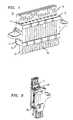
- FIG. 1Illustrated in FIG. 1 is a module, 10, which can be inserted into a frame (not shown) along with other similar modules to form a connecting block.
- the moduleincludes a housing which is made of insulating material such as plastic.
- the housingincludes an essentially rectangular body portion, 11, which is covered by caps, 14 and 15.
- the capscan be made of the same material as the housing and define an upper and lower surface, 12 and 13, respectively, for the housing.
- Each capincludes a series of slits, e.g., 16, which permit insertion of a wire (e.g., 61 of FIG. 4) therein as discussed below.
- Each capalso includes a series of slots, e.g., 17 and 18 of FIGS.
- each contact, 30 and 31includes an end portion, 32 and 33, respectively, which is capable of providing electrical connection to a wire, 60 and 61, respectively.
- the end portionseach comprise a slot, 34 and 35, which pierces the insulation surrounding the wire to establish electrical contact as the wire is inserted to proper depth.
- the contactsare mounted so that the end portions of the first row of contacts, e.g., 30, protrude through the top surface, 12, of the housing, while the end portions of the second row of contacts, e.g., 31, protrude through the bottom surface, 13, of the housing.
- the end portions, e.g., 33are also aligned with corresponding slits, e.g., 16 of FIG. 1, in the caps, e.g., 15 of FIG.. 1, so that wires, e.g., 61, may be inserted through the caps for electrical connection by the contacts.
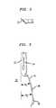
- the faces of the end portions, e.g., 32are advantageously at an angle of approximately 45 degrees with the longitudinal axis of the stem portions, e.g., 42.
- the stem portion, e.g., 42, of each contact, e.g., 30,extends from the end portion at a first angle, ⁇ 1 , from an edge of the end portion in the plane of the longitudinal axis, and further down the stem, extends at a second angle, ⁇ 2 , from the edge of the end portion.
- ⁇ 1was 17 degrees and ⁇ 2 was 2 degrees.
- ⁇ 1is in the range of 10 to 20 degrees, while ⁇ 2 is in the range -10 to +20 degrees.
- Use of a double angleis advantageous in narrowing the width (w) of the housing portion, 11, by permitting the end portions to be placed closer together.
- leads with a single anglemay be employed. It will be appreciated that the contacts in the first and second rows may be identical, but oriented in opposite directions.
- the stem portionseach include a pair of raised portions, 44 and 45, which are plated with a precious metal or alloy to provide electrical contact As illustrated in FIGS. 4-7, these raised portions establish two points of electrical contact, 38 and 39, between corresponding contacts, 30 and 31, of the first and second rows.
- Each top point of contact, e.g., 38is aligned with a slot, e.g., 17, in the top surface, 12, while each bottom point of contact, 39, is aligned with a slot, e.g., 18, in the bottom surface of the housing.
- stem 43would be deflected more than stem 42 since the bending moment of stem 43 would be measured from contact 38 to the bottom surface, while the bending moment of stem 42 would be measured from the top surface to contact point 38.
- a lead, 41, attached to a test cord, 22,can be inserted into the slot, 17, on the surface of the housing opposite to the protector, 21.
- the test lead, 41will push apart further the point of contact, 38, not occupied by the protector lead.
- the stem 43will remain in contact with the protector lead to continue to provide protection to the cable and circuitry (not shown) coupled to the bottom end portions, e.g., 33.
- the stem 42 coupled to end portion 32will separate from the protector lead 40 in order to permit testing in both directions independently while providing voltage surge protection to the circuit.
- the displacement of stem 42 away from lead 40is advantageously produced by a type of lead, 41, for the test probe which is illustrated in FIG. 10.
- the leadbasically comprises an insulating substrate, 55, such as epoxy glass with a thickness, typically, of approximately 1-2 mm.
- the substrate, 55includes a pair of conductors, 46 and 47, on one surface, and a pair of conductors, 48 and 49, on the opposite surface.
- the thickness of the conductors, 46 and 47, on one surfaceis significantly greater than the thickness of the conductors, 48 and 49, on the opposite surface.
- the thickness of conductors 46 and 47is 0.50 mm, while the thickness of the conductors 48 and 49 is 0.25 mm.
- the thickness of one pairshould be at least two times greater than the thickness of the other pair.
- stem 42will be displaced an additional amount to separate it from the protector lead, 40.
- a series of ribse.g., 80, is provided between the stem portions, e.g., 42 and 43, of each contact pair, 30 and 31, and extending across the width of the body portion, 11.
- Each rib, 80includes a channel, 81, aligned with a slot, 17, in the top surface of the housing, and a channel, 82, (partly obscured in this view), aligned with a slot, 18, in the bottom surface of the housing.
- Each channel, 81 or 82captures a portion of the lead, 41 or 40 of FIGS. 6-7, inserted into a corresponding slot, 17 or 18.
- the channels, 81 and 82prevent bending of the leads, 41 and 40, as they are inserted, and, therefore, prevent excessive deflection of the stem portions, 42 and 43, which could result in the stems being bent beyond their elastic limit. Also, since the slots, 17 and 18, and corresponding channels, 81 and 82, are offset to align with a corresponding contact point, 38 and 39 of FIG. 4, the rib, 80, can also serve to aid the desired deflections of the stem portions previously described.
- the body portion, 11,need not be open on the top and bottom and covered by a cap as shown, but can have its own top and bottom surface with either no cap or with a cap which covers only the end portions of the contacts.
- the connector module described hereinhas several advantages. For example, it permits cable wires, e.g., 61, to be connected to one row of contacts, e.g., 31, and cross-connect wires, e.g., 60, to be connected to the other row of contacts, e.g., 30, on the opposite surface of the module.
- the double contact points for electrically connecting contacts of the two rowspermit a lead to be inserted into one point before the other point is separated thus establishing a make-before-break contact.
- the double contact pointsalso permit test access from one surface of the module while a protector is mounted on the other surface to provide continuing protection.
Landscapes
- Engineering & Computer Science (AREA)
- Computer Networks & Wireless Communication (AREA)
- Coupling Device And Connection With Printed Circuit (AREA)
- Connections Arranged To Contact A Plurality Of Conductors (AREA)
- Measuring Leads Or Probes (AREA)
- Connecting Device With Holders (AREA)
- Details Of Connecting Devices For Male And Female Coupling (AREA)
Description
- This invention relates to modules for electrically connecting sets ofwires.
- In the telecommunications industry, connecting blocks comprising anarray of insulation displacement contacts are typically used in telephone centraloffices, building entrance terminals, and outside plant cabinets for electricalconnection between cables and cross-connect wiring. One example of such aconnecting block is the standard 110-type connector block. (See, for example, U.S.Patent No. 3,798,587.) Such connector blocks include rows of insulationdisplacement contacts mounted within a plastic module. Each contact includesinsulation piercing slots on both ends. One set of wires is placed within a (index)strip, and the contact module is placed over the wires in order to make contacttherewith. A second set of wires is inserted into the opposite end of the contacts tocomplete the electrical connection between the sets of wires. In some recentsystems, connector modules include slots for mounting protectors which areelectrically connected to the contacts. (See, for example, U.S. Patents 4,171,857 and4,283,103.)
- While the prior art blocks are adequate, wiring was generally done on asingle surface, and when protector components were also mounted on the block, itwas necessary to remove the protectors before inserting jumper wires or test probes.In accordance with EP-A-96 303 204filed on an even date herewith, a module is described which permits wiring on twosurfaces and insertion of patch cords or test leads into one surface while a protectorcomponent is mounted on the opposite surface. In such modules, it is desirable toensure that the protector remains connected to at least some contacts when a testprobe is inserted in the block so that protection is not interrupted. Further, it isdesirable to have a "make-before- break" capacity so that signaling is not interruptedwhen a patch cord or test access lead is inserted.
- The invention is a connector module which includes two rows ofcontacts mounted within an insulating housing having a top and bottom surface.Each contact includes an end portion which is capable of providing electricalconnection to a corresponding wire, and a stem portion. The contacts are mountedso that the end portions of the first row extend through the top surface and the end portions of the second row extend through the bottom surface. The stem portions ofcorresponding contacts of the first and second rows extend into the housing andmake electrical contact on at least two points of the stem portions. The points ofcontact are aligned with slots in the top and bottom surfaces.
- These and other features of the invention are delineated in detail in thefollowing description. In the drawing:
- FIG. 1 is a perspective view of a module in accordance with anembodiment of the invention;
- FIGS. 2 and 3 are top and side views, respectively, of a contact inaccordance with the same embodiment;
- FIGS. 4-7 are cross-sectional views of a module in accordance with thesame embodiment;
- FIG. 8 is a perspective, partly cut-away view of a portion of the modulein accordance with the same embodiment;
- FIG. 9 is a further perspective view of the module in accordance withthe same embodiment; and
- FIG. 10 is an end view of a lead which may be used with the module inaccordance with the same embodiment.
- It will be appreciated that, for purposes of illustration, these figures arenot necessarily drawn to scale.
- Illustrated in FIG. 1 is a module, 10, which can be inserted into a frame(not shown) along with other similar modules to form a connecting block. Themodule includes a housing which is made of insulating material such as plastic. Thehousing, includes an essentially rectangular body portion, 11, which is covered bycaps, 14 and 15. The caps can be made of the same material as the housing anddefine an upper and lower surface, 12 and 13, respectively, for the housing. Eachcap includes a series of slits, e.g., 16, which permit insertion of a wire (e.g., 61 ofFIG. 4) therein as discussed below. Each cap also includes a series of slots, e.g., 17and 18 of FIGS. 1 and 4, in the top and bottom surfaces, 12 and 13, of the housing,which slots permit insertion of leads, e.g., 40 and 41, which may be electricallycoupled to a single protector, 21 of FIG. 5, a test probe, 22 of FIG. 7, a patch cord,50 of FIG. 9 , a cartridge protector (not shown), or possibly other components.
- As illustrated in FIGS. 4-7, mounted within the housing is a first row ofcontacts, e.g., 30, and a second row of contacts, e.g., 31, one of which contacts (30)is illustrated in more detail in FIGS. 2 and 3. Each contact, 30 and 31, includes anend portion, 32 and 33, respectively, which is capable of providing electricalconnection to a wire, 60 and 61, respectively. In this embodiment, the end portionseach comprise a slot, 34 and 35, which pierces the insulation surrounding the wire toestablish electrical contact as the wire is inserted to proper depth. The contacts aremounted so that the end portions of the first row of contacts, e.g., 30, protrudethrough the top surface, 12, of the housing, while the end portions of the second rowof contacts, e.g., 31, protrude through the bottom surface, 13, of the housing. Theend portions, e.g., 33, are also aligned with corresponding slits, e.g., 16 of FIG. 1, inthe caps, e.g., 15 of FIG.. 1, so that wires, e.g., 61, may be inserted through the capsfor electrical connection by the contacts.
- The remainder of the contacts, 30 and 31, also known as the stemportions, 42 and 43, respectively, extend in the body portion, 11. As illustrated inFIG. 2, the faces of the end portions, e.g., 32, are advantageously at an angle ofapproximately 45 degrees with the longitudinal axis of the stem portions, e.g., 42.As illustrated in FIG. 3, the stem portion, e.g., 42, of each contact, e.g., 30, extendsfrom the end portion at a first angle, Θ1, from an edge of the end portion in the planeof the longitudinal axis, and further down the stem, extends at a second angle, Θ2,from the edge of the end portion. In this particular example, Θ1 was 17 degrees andΘ2 was 2 degrees. Typically, Θ1 is in the range of 10 to 20 degrees, while Θ2 is inthe range -10 to +20 degrees. Use of a double angle is advantageous in narrowingthe width (w) of the housing portion, 11, by permitting the end portions to be placedcloser together. However, leads with a single angle may be employed. It will beappreciated that the contacts in the first and second rows may be identical, butoriented in opposite directions.
- The stem portions, e.g., 42, each include a pair of raised portions, 44 and45, which are plated with a precious metal or alloy to provide electrical contact Asillustrated in FIGS. 4-7, these raised portions establish two points of electricalcontact, 38 and 39, between corresponding contacts, 30 and 31, of the first andsecond rows. Each top point of contact, e.g., 38, is aligned with a slot, e.g., 17, inthe top surface, 12, while each bottom point of contact, 39, is aligned with a slot,e.g., 18, in the bottom surface of the housing.
- As illustrated in FIG. 5, when the lead, 40, coupled to a protector, 21,(or to a patch cord such as shown as 50 in FIG. 9), is inserted into a desired slot, e.g.,18, it will initially push apart the two stem portions, 42 and 43, at the contact point,39, aligned with the slot. However, the stems at the other contact point, 38, willinitially remain touching to ensure a "make-before-break" connection so as not tointerrupt signaling between the two contacts, 30 and 31. (In actual practice, a make-before-breakfeature is generally not needed to plug in a protector, but the principleis demonstrated with the use of
protector 21.) - Such a make-before-break capability is possible due to a number offeatures. Primarily, the
point 38 remains closed even when thepoint 39 is openeddue to the fact that when a lead is inserted intopoint 39 from the bottom as shown,the deflection ofstem 42 is greater than the deflection ofstem 43. This is becausethe bending moment ofstem 43 is dependent upon the distance (a) from the bottomsurface of the housing to the point ofcontact 39, while the bending moment ofstem 42 is dependent upon the distance (b) from the top surface of the housing to the pointofcontact 39. Clearly, the distance (b) is greater than the distance (a), and,consequently, the displacement ofstem 42 is greater than the displacement ofstem 43 thereby urging the surface (44 of FIG. 3) ofstem 42 into contact with thecorresponding surface ofstem 43 atcontact point 38 whilecontact point 39 isopening. It will be appreciated that the same principles operate in reverse if a leadwere to be inserted from the top, i.e.,stem 43 would be deflected more thanstem 42since the bending moment ofstem 43 would be measured fromcontact 38 to thebottom surface, while the bending moment ofstem 42 would be measured from thetop surface tocontact point 38. - As illustrated in FIG. 6, the other point of contact, 38, will eventuallyseparate as the lead is further inserted through the two stem portions, and theprotector, 21, is seated on the bottom surface, 13, of the housing. Consequently,with the protector, 21, in its final position, current between the contacts, 30 and 31,will flow only through the protector. The same sequence depicted in FIGS. 5 and 6will occur when a patch cord such as shown in FIG. 9 is inserted into one of theslots, e.g., 17 or 18.
- If at some point it is desired to provide test access to the contacts, 30and 31, as illustrated in FIG. 7, a lead, 41, attached to a test cord, 22, can be insertedinto the slot, 17, on the surface of the housing opposite to the protector, 21. The testlead, 41, will push apart further the point of contact, 38, not occupied by theprotector lead. However, due to the bending moments previously described, the
stem 43 will remain in contact with the protector lead to continue to provideprotection to the cable and circuitry (not shown) coupled to the bottom end portions,e.g., 33. However, thestem 42 coupled to endportion 32 will separate from theprotector lead 40 in order to permit testing in both directions independently whileproviding voltage surge protection to the circuit. - The displacement of
stem 42 away fromlead 40 is advantageouslyproduced by a type of lead, 41, for the test probe which is illustrated in FIG. 10. - The lead basically comprises an insulating substrate, 55, such as epoxyglass with a thickness, typically, of approximately 1-2 mm. The substrate, 55,includes a pair of conductors, 46 and 47, on one surface, and a pair of conductors, 48and 49, on the opposite surface. It will be noted that the thickness of the conductors,46 and 47, on one surface is significantly greater than the thickness of theconductors, 48 and 49, on the opposite surface. Typically, the thickness of
conductors conductors - It will be appreciated that by inserting the
lead 41 so that the thickercontact, e.g., 47, makes contact withstem 42 while the thinner contact, e.g., 49,makes contact with stem 43 (and the other contacts, 46 and 48, make similar contactwith an adjacent pair of contacts (not shown) in the row), stem 42 will be displacedan additional amount to separate it from the protector lead, 40. - As illustrated in FIG. 8, a series of ribs, e.g., 80, is provided between thestem portions, e.g., 42 and 43, of each contact pair, 30 and 31, and extending acrossthe width of the body portion, 11. Each rib, 80, includes a channel, 81, aligned witha slot, 17, in the top surface of the housing, and a channel, 82, (partly obscured inthis view), aligned with a slot, 18, in the bottom surface of the housing. Eachchannel, 81 or 82, captures a portion of the lead, 41 or 40 of FIGS. 6-7, inserted intoa corresponding slot, 17 or 18.
- It will be appreciated that the channels, 81 and 82, prevent bending ofthe leads, 41 and 40, as they are inserted, and, therefore, prevent excessive deflectionof the stem portions, 42 and 43, which could result in the stems being bent beyondtheir elastic limit. Also, since the slots, 17 and 18, and corresponding channels, 81and 82, are offset to align with a corresponding contact point, 38 and 39 of FIG. 4,the rib, 80, can also serve to aid the desired deflections of the stem portionspreviously described.
- Various modifications of the embodiment described herein will becomeapparent to those skilled in the art. For example, the body portion, 11, need not beopen on the top and bottom and covered by a cap as shown, but can have its own topand bottom surface with either no cap or with a cap which covers only the endportions of the contacts.
- Thus, it will be appreciated that the connector module described hereinhas several advantages. For example, it permits cable wires, e.g., 61, to beconnected to one row of contacts, e.g., 31, and cross-connect wires, e.g., 60, to beconnected to the other row of contacts, e.g., 30, on the opposite surface of themodule. At the same time, the double contact points for electrically connectingcontacts of the two rows permit a lead to be inserted into one point before the otherpoint is separated thus establishing a make-before-break contact. The double contactpoints also permit test access from one surface of the module while a protector ismounted on the other surface to provide continuing protection.
Claims (6)
- A connector module comprising:CHARACTERIZED BY:an insulating housing (11, 14, 15) having a top and bottom surface (12,13);first and second rows of contacts (30, 31) mounted within the housing,each contact including an end portion (32, 33) which is capable of providingelectrical connection to a corresponding wire (60, 61) and a stem portion (42, 43),the contacts being mounted so that the end portions of the first rowextend through the top surface (12) and the end portions of the second row extendthrough the bottom surface (13), the end portions of the first and second rows beinglaterally displaced, and the top and bottom surfaces including slots (17, 18) adjacentto the corresponding rows for receiving therein leads which make electrical contactwith corresponding contacts, the stem portions of corresponding contacts of the firstand second rows making electrical contact on at least two contact points (38, 39),one contact point (38) being aligned with a slot (17) in the top surface and the othercontact (39) point being aligned with a slot (18) in the bottom surface.
- A connector module according to claim 1 wherein each end portionprovides electrical connection by means of an insulation piercing slot (34, 35).
- A connector module according to claim 1 wherein the contact points(38, 39) include raised surfaces (44, 45) of the stem portions of the correspondingcontacts.
- A connector according to claim 3 wherein the raised surfaces arecoated with a material selected from the group consisting of gold, silver andpalladium.
- A connector according to claim 3 wherein each stem portioncomprises at least two segments which extend from the end portion at first andsecond angles (Θ1, Θ2) from an edge of the end portion, and the raised surfaces arelocated at the ends of the segments.
- A connector module according to claim 1 wherein the insulating bodycomprises a series of ribs (80) adjacent to the stem portions of corresponding contacts and positioned so as to prevent bending of the leads inserted into the slots asthe leads make contact with their corresponding stem portions.
Applications Claiming Priority (2)
| Application Number | Priority Date | Filing Date | Title |
|---|---|---|---|
| US442863 | 1995-05-17 | ||
| US08/442,863US5549489A (en) | 1995-05-17 | 1995-05-17 | Connector module with test and jumper access |
Publications (2)
| Publication Number | Publication Date |
|---|---|
| EP0743710A1 EP0743710A1 (en) | 1996-11-20 |
| EP0743710B1true EP0743710B1 (en) | 1999-09-22 |
Family
ID=23758450
Family Applications (1)
| Application Number | Title | Priority Date | Filing Date |
|---|---|---|---|
| EP96303205AExpired - LifetimeEP0743710B1 (en) | 1995-05-17 | 1996-05-08 | Connector module with test and jumper access |
Country Status (12)
| Country | Link |
|---|---|
| US (1) | US5549489A (en) |
| EP (1) | EP0743710B1 (en) |
| JP (1) | JP3450121B2 (en) |
| KR (1) | KR100379593B1 (en) |
| CN (1) | CN1064783C (en) |
| BR (1) | BR9602289A (en) |
| CA (1) | CA2174888C (en) |
| DE (1) | DE69604331T2 (en) |
| MY (1) | MY114923A (en) |
| PL (1) | PL180704B1 (en) |
| TW (1) | TW289869B (en) |
| ZA (1) | ZA963723B (en) |
Cited By (2)
| Publication number | Priority date | Publication date | Assignee | Title |
|---|---|---|---|---|
| DE102007026111A1 (en) | 2007-06-05 | 2008-12-11 | Adc Gmbh | Terminal block and contact element for telecommunications and data technology |
| DE102009024330A1 (en)* | 2009-06-09 | 2010-12-16 | Adc Gmbh | terminal block |
Families Citing this family (28)
| Publication number | Priority date | Publication date | Assignee | Title |
|---|---|---|---|---|
| US5618199A (en)* | 1995-05-17 | 1997-04-08 | Lucent Technologies Inc. | Connector module including condensation protection |
| US5718593A (en) | 1995-07-03 | 1998-02-17 | Lucent Technologies Inc. | Polarity-sensitive protector device |
| US5722850A (en)* | 1995-11-27 | 1998-03-03 | Molex Incorporated | Telecommunications connectors |
| US6074257A (en)* | 1998-10-06 | 2000-06-13 | Porta Systems Corp. | Electrical connection strip with pivoting conductor guide |
| US6994582B1 (en)* | 2002-12-20 | 2006-02-07 | Porta Systems Corporation | Connector module |
| US7101216B2 (en)* | 2004-09-15 | 2006-09-05 | 3M Innovative Properties Company | Insulation displacement system for two electrical conductors |
| US7335049B2 (en)* | 2004-09-15 | 2008-02-26 | 3M Innovative Properties Company | Connector assembly for housing insulation displacement elements |
| US7458840B2 (en)* | 2004-09-15 | 2008-12-02 | 3M Innovative Properties Company | Cap configured to removably connect to an insulation displacement connector block |
| US7399197B2 (en)* | 2004-09-15 | 2008-07-15 | 3M Innovative Properties Company | Connector assembly for housing insulation displacement elements |
| US20060264090A1 (en)* | 2005-05-18 | 2006-11-23 | Dower William V | Electrical connector assembly and method of forming the same |
| US7303446B2 (en)* | 2005-05-18 | 2007-12-04 | 3M Innovative Proprties Company | Frame assembly |
| US7165983B1 (en) | 2005-12-08 | 2007-01-23 | 3M Innovative Properties Company | Access cover configured to receive a testing device |
| US7335069B1 (en)* | 2006-11-28 | 2008-02-26 | Commscope, Inc. Of North Carolina | Plugless normally-open connector module |
| DE102007026095A1 (en)* | 2007-06-05 | 2008-12-11 | Adc Gmbh | Earth comb, in particular for a connector for printed circuit boards |
| DE102007026097B4 (en)* | 2007-06-05 | 2023-05-11 | Tyco Electronics Services Gmbh | Connectors for printed circuit boards |
| DE102007026094B4 (en)* | 2007-06-05 | 2023-05-11 | Tyco Electronics Services Gmbh | Contact element for a connector for printed circuit boards |
| DE102007026096A1 (en)* | 2007-06-05 | 2008-12-11 | Adc Gmbh | Cable termination module |
| DE102007026102B3 (en)* | 2007-06-05 | 2008-11-13 | Adc Gmbh | Connectors for printed circuit boards |
| WO2010087539A1 (en)* | 2009-02-02 | 2010-08-05 | Park Joon Eon | Connector system for semiconductor test device |
| GB0910199D0 (en)* | 2009-06-15 | 2009-07-29 | 3M Innovative Properties Co | Symmetrical termination strip for a telecommunications moduel |
| JP2012530331A (en)* | 2009-06-15 | 2012-11-29 | スリーエム イノベイティブ プロパティズ カンパニー | Termination strip and mounting method for communication modules |
| CN102804520A (en)* | 2009-06-15 | 2012-11-28 | 3M创新有限公司 | Connection and switching contact elements for a termination strip for a telecommunications module |
| DE102009056295A1 (en)* | 2009-11-30 | 2011-06-09 | Adc Gmbh | rail |
| EP2566181A1 (en) | 2011-08-31 | 2013-03-06 | 3M Innovative Properties Company | Functional module for a telecommunication strip for a telecommunications system |
| DE102012022644B4 (en)* | 2012-11-12 | 2022-08-04 | Tyco Electronics Services Gmbh | Distribution module and method of connecting wires |
| TWI610505B (en)* | 2015-05-13 | 2018-01-01 | 町洋企業股份有限公司 | Connector module |
| CN106299776B (en)* | 2015-05-25 | 2018-08-28 | 町洋企业股份有限公司 | Connector module |
| CN106469876B (en)* | 2015-08-17 | 2018-11-23 | 町洋企业股份有限公司 | Connector module |
Family Cites Families (15)
| Publication number | Priority date | Publication date | Assignee | Title |
|---|---|---|---|---|
| US3308422A (en)* | 1965-08-19 | 1967-03-07 | Donald C Boysen | Bridging connector for telephone terminal blocks |
| US3588785A (en)* | 1969-12-03 | 1971-06-28 | Ibm | Connector assembly |
| BE794021A (en)* | 1972-01-17 | 1973-05-02 | Western Electric Co | PERFECTED WIRE CONNECTION BLOCK |
| US3966074A (en)* | 1975-04-28 | 1976-06-29 | Proto Production Plastics, Inc. | Terminal box and cover |
| FR2341974A1 (en)* | 1976-02-18 | 1977-09-16 | Causse Raoul | LOW VOLTAGE LINE PROTECTION DEVICE, ESPECIALLY FOR TELEPHONE NETWORKS |
| US4059331A (en)* | 1976-02-20 | 1977-11-22 | Reliable Electric Company | Terminal block |
| DE2725551C2 (en)* | 1977-06-07 | 1983-11-17 | Krone Gmbh, 1000 Berlin | Electrical clamp connector |
| DE2804478C2 (en)* | 1978-01-31 | 1982-11-25 | Krone Gmbh, 1000 Berlin | Electrical clamp connector for the production of a contact on a fixed connection element without soldering, screwing or stripping, in particular for telecommunication line technology |
| FR2423105A1 (en)* | 1978-04-10 | 1979-11-09 | Carpano & Pons | CONNECTION BLOCK FOR TELEPHONE SYSTEMS |
| FR2426345A1 (en)* | 1978-05-18 | 1979-12-14 | Carpano & Pons | CONNECTION BODY, FOR TELEPHONE SYSTEMS |
| DE3710896A1 (en)* | 1987-04-01 | 1988-10-20 | Krone Ag | DISTRIBUTION BOARD FOR TELECOMMUNICATION CABLES, IN PARTICULAR HOUSE ENTRANCE DISTRIBUTION BOARD |
| DE3726741C1 (en)* | 1987-08-07 | 1988-09-01 | Krone Ag | Terminal block of telecommunications technology |
| DE3909783C2 (en)* | 1989-03-22 | 1996-06-13 | Krone Ag | Protective plug for terminal strips in telecommunications and data technology |
| DE4015238A1 (en)* | 1990-05-10 | 1991-11-14 | Krone Ag | CONNECTION BAR FOR TELECOMMUNICATION TECHNOLOGY |
| US5364288A (en)* | 1992-07-24 | 1994-11-15 | North American Philips Corporation | Electrical connecting device |
- 1995
- 1995-05-17USUS08/442,863patent/US5549489A/ennot_activeExpired - Lifetime
- 1995-06-13TWTW084106011Apatent/TW289869B/zhnot_activeIP Right Cessation
- 1996
- 1996-04-24CACA002174888Apatent/CA2174888C/ennot_activeExpired - Fee Related
- 1996-05-08EPEP96303205Apatent/EP0743710B1/ennot_activeExpired - Lifetime
- 1996-05-08DEDE69604331Tpatent/DE69604331T2/ennot_activeExpired - Lifetime
- 1996-05-10ZAZA963723Apatent/ZA963723B/enunknown
- 1996-05-14MYMYPI96001811Apatent/MY114923A/enunknown
- 1996-05-14PLPL96314223Apatent/PL180704B1/ennot_activeIP Right Cessation
- 1996-05-16JPJP12072696Apatent/JP3450121B2/ennot_activeExpired - Fee Related
- 1996-05-16CNCN96105870Apatent/CN1064783C/ennot_activeExpired - Fee Related
- 1996-05-16BRBR9602289Apatent/BR9602289A/ennot_activeIP Right Cessation
- 1996-05-16KRKR1019960016419Apatent/KR100379593B1/ennot_activeExpired - Fee Related
Cited By (2)
| Publication number | Priority date | Publication date | Assignee | Title |
|---|---|---|---|---|
| DE102007026111A1 (en) | 2007-06-05 | 2008-12-11 | Adc Gmbh | Terminal block and contact element for telecommunications and data technology |
| DE102009024330A1 (en)* | 2009-06-09 | 2010-12-16 | Adc Gmbh | terminal block |
Also Published As
| Publication number | Publication date |
|---|---|
| JP3450121B2 (en) | 2003-09-22 |
| CN1064783C (en) | 2001-04-18 |
| TW289869B (en) | 1996-11-01 |
| JPH08330036A (en) | 1996-12-13 |
| DE69604331T2 (en) | 2000-05-11 |
| ZA963723B (en) | 1997-07-31 |
| HK1003757A1 (en) | 1998-11-06 |
| US5549489A (en) | 1996-08-27 |
| DE69604331D1 (en) | 1999-10-28 |
| CN1141519A (en) | 1997-01-29 |
| KR960043354A (en) | 1996-12-23 |
| PL180704B1 (en) | 2001-03-30 |
| MX9601709A (en) | 1997-07-31 |
| MY114923A (en) | 2003-02-28 |
| CA2174888C (en) | 2000-04-11 |
| KR100379593B1 (en) | 2003-09-29 |
| CA2174888A1 (en) | 1996-11-18 |
| EP0743710A1 (en) | 1996-11-20 |
| BR9602289A (en) | 1998-01-13 |
| PL314223A1 (en) | 1996-11-25 |
Similar Documents
| Publication | Publication Date | Title |
|---|---|---|
| EP0743710B1 (en) | Connector module with test and jumper access | |
| CA2174268C (en) | Connector modules | |
| US5647760A (en) | Insulation displacement contact including retention means | |
| US4116524A (en) | Terminal bridging assembly | |
| US4118091A (en) | Electrical connection assemblies | |
| US5622516A (en) | Insulation displacement terminal with two-wire insertion capability | |
| US7534149B2 (en) | Plugless normally-open connector module | |
| US4925393A (en) | 66 Block adapter | |
| US5004433A (en) | Interconnection device | |
| US5643014A (en) | Mounting of protectors in connector blocks | |
| US5244408A (en) | Terminal housing | |
| US6074257A (en) | Electrical connection strip with pivoting conductor guide | |
| US6129575A (en) | Testing system for a connector with a self-sealing connector housing | |
| US5476388A (en) | Connector block | |
| HK1003757B (en) | Connector module with test and jumper access | |
| US4813071A (en) | Laminar type telephone connector block | |
| USRE35476E (en) | Electrical connector block | |
| US5618199A (en) | Connector module including condensation protection | |
| MXPA96001709A (en) | Connection module with proof and pue access | |
| HK1003758B (en) | Connector modules | |
| MXPA96001819A (en) | Connected modules |
Legal Events
| Date | Code | Title | Description |
|---|---|---|---|
| PUAI | Public reference made under article 153(3) epc to a published international application that has entered the european phase | Free format text:ORIGINAL CODE: 0009012 | |
| AK | Designated contracting states | Kind code of ref document:A1 Designated state(s):DE FR GB IT NL SE | |
| 17P | Request for examination filed | Effective date:19970509 | |
| GRAG | Despatch of communication of intention to grant | Free format text:ORIGINAL CODE: EPIDOS AGRA | |
| 17Q | First examination report despatched | Effective date:19981016 | |
| GRAG | Despatch of communication of intention to grant | Free format text:ORIGINAL CODE: EPIDOS AGRA | |
| GRAH | Despatch of communication of intention to grant a patent | Free format text:ORIGINAL CODE: EPIDOS IGRA | |
| GRAH | Despatch of communication of intention to grant a patent | Free format text:ORIGINAL CODE: EPIDOS IGRA | |
| GRAA | (expected) grant | Free format text:ORIGINAL CODE: 0009210 | |
| AK | Designated contracting states | Kind code of ref document:B1 Designated state(s):DE FR GB IT NL SE | |
| REF | Corresponds to: | Ref document number:69604331 Country of ref document:DE Date of ref document:19991028 | |
| ITF | It: translation for a ep patent filed | ||
| ET | Fr: translation filed | ||
| PLBQ | Unpublished change to opponent data | Free format text:ORIGINAL CODE: EPIDOS OPPO | |
| PLBI | Opposition filed | Free format text:ORIGINAL CODE: 0009260 | |
| PLBF | Reply of patent proprietor to notice(s) of opposition | Free format text:ORIGINAL CODE: EPIDOS OBSO | |
| PLBF | Reply of patent proprietor to notice(s) of opposition | Free format text:ORIGINAL CODE: EPIDOS OBSO | |
| PLAB | Opposition data, opponent's data or that of the opponent's representative modified | Free format text:ORIGINAL CODE: 0009299OPPO | |
| 26 | Opposition filed | Opponent name:KRONE AG Effective date:20000621 | |
| R26 | Opposition filed (corrected) | Opponent name:KRONE GMBH Effective date:20000621 | |
| NLR1 | Nl: opposition has been filed with the epo | Opponent name:KRONE AG | |
| NLR1 | Nl: opposition has been filed with the epo | Opponent name:KRONE GMBH | |
| PLBF | Reply of patent proprietor to notice(s) of opposition | Free format text:ORIGINAL CODE: EPIDOS OBSO | |
| REG | Reference to a national code | Ref country code:GB Ref legal event code:IF02 | |
| PLBO | Opposition rejected | Free format text:ORIGINAL CODE: EPIDOS REJO | |
| PLBN | Opposition rejected | Free format text:ORIGINAL CODE: 0009273 | |
| STAA | Information on the status of an ep patent application or granted ep patent | Free format text:STATUS: OPPOSITION REJECTED | |
| 27O | Opposition rejected | Effective date:20030222 | |
| NLR2 | Nl: decision of opposition | Effective date:20030222 | |
| PGFP | Annual fee paid to national office [announced via postgrant information from national office to epo] | Ref country code:NL Payment date:20100524 Year of fee payment:15 Ref country code:IT Payment date:20100527 Year of fee payment:15 | |
| PGFP | Annual fee paid to national office [announced via postgrant information from national office to epo] | Ref country code:SE Payment date:20100527 Year of fee payment:15 | |
| PGFP | Annual fee paid to national office [announced via postgrant information from national office to epo] | Ref country code:FR Payment date:20110607 Year of fee payment:16 | |
| PGFP | Annual fee paid to national office [announced via postgrant information from national office to epo] | Ref country code:GB Payment date:20110525 Year of fee payment:16 | |
| PGFP | Annual fee paid to national office [announced via postgrant information from national office to epo] | Ref country code:DE Payment date:20110527 Year of fee payment:16 | |
| REG | Reference to a national code | Ref country code:NL Ref legal event code:V1 Effective date:20111201 | |
| REG | Reference to a national code | Ref country code:SE Ref legal event code:EUG | |
| PG25 | Lapsed in a contracting state [announced via postgrant information from national office to epo] | Ref country code:NL Free format text:LAPSE BECAUSE OF NON-PAYMENT OF DUE FEES Effective date:20111201 | |
| PG25 | Lapsed in a contracting state [announced via postgrant information from national office to epo] | Ref country code:IT Free format text:LAPSE BECAUSE OF NON-PAYMENT OF DUE FEES Effective date:20110508 | |
| GBPC | Gb: european patent ceased through non-payment of renewal fee | Effective date:20120508 | |
| REG | Reference to a national code | Ref country code:FR Ref legal event code:ST Effective date:20130131 | |
| REG | Reference to a national code | Ref country code:DE Ref legal event code:R119 Ref document number:69604331 Country of ref document:DE Effective date:20121201 | |
| PG25 | Lapsed in a contracting state [announced via postgrant information from national office to epo] | Ref country code:GB Free format text:LAPSE BECAUSE OF NON-PAYMENT OF DUE FEES Effective date:20120508 Ref country code:FR Free format text:LAPSE BECAUSE OF NON-PAYMENT OF DUE FEES Effective date:20120531 Ref country code:SE Free format text:LAPSE BECAUSE OF NON-PAYMENT OF DUE FEES Effective date:20110509 | |
| PG25 | Lapsed in a contracting state [announced via postgrant information from national office to epo] | Ref country code:DE Free format text:LAPSE BECAUSE OF NON-PAYMENT OF DUE FEES Effective date:20121201 |