EP0743422B1 - Downhole packing assembly - Google Patents
Downhole packing assemblyDownload PDFInfo
- Publication number
- EP0743422B1 EP0743422B1EP96303392AEP96303392AEP0743422B1EP 0743422 B1EP0743422 B1EP 0743422B1EP 96303392 AEP96303392 AEP 96303392AEP 96303392 AEP96303392 AEP 96303392AEP 0743422 B1EP0743422 B1EP 0743422B1
- Authority
- EP
- European Patent Office
- Prior art keywords
- slip
- mandrel
- shoe
- segments
- packer
- Prior art date
- Legal status (The legal status is an assumption and is not a legal conclusion. Google has not performed a legal analysis and makes no representation as to the accuracy of the status listed.)
- Expired - Lifetime
Links
- 238000012856packingMethods0.000titledescription6
- 239000000463materialSubstances0.000claimsdescription17
- 239000002131composite materialSubstances0.000claimsdescription14
- 239000007769metal materialSubstances0.000claimsdescription12
- 230000000717retained effectEffects0.000claimsdescription9
- ISWSIDIOOBJBQZ-UHFFFAOYSA-Nphenol groupChemical groupC1(=CC=CC=C1)OISWSIDIOOBJBQZ-UHFFFAOYSA-N0.000claimsdescription6
- 238000005553drillingMethods0.000description17
- 238000003801millingMethods0.000description13
- 239000004033plasticSubstances0.000description13
- 229920003023plasticPolymers0.000description13
- 238000000034methodMethods0.000description9
- 238000012360testing methodMethods0.000description7
- 235000013824polyphenolsNutrition0.000description6
- 239000012530fluidSubstances0.000description5
- 229910001018Cast ironInorganic materials0.000description4
- 230000008901benefitEffects0.000description4
- 239000002184metalSubstances0.000description4
- 229910052751metalInorganic materials0.000description4
- 229910001369BrassInorganic materials0.000description3
- 229910000831SteelInorganic materials0.000description3
- 239000010951brassSubstances0.000description3
- 230000000295complement effectEffects0.000description3
- 230000035515penetrationEffects0.000description3
- 239000002002slurrySubstances0.000description3
- 239000010959steelSubstances0.000description3
- 2299100007881018 steelInorganic materials0.000description2
- XEEYBQQBJWHFJM-UHFFFAOYSA-NIronChemical compound[Fe]XEEYBQQBJWHFJM-UHFFFAOYSA-N0.000description2
- MCMNRKCIXSYSNV-UHFFFAOYSA-NZirconium dioxideChemical compoundO=[Zr]=OMCMNRKCIXSYSNV-UHFFFAOYSA-N0.000description2
- 230000000712assemblyEffects0.000description2
- 238000000429assemblyMethods0.000description2
- 238000005520cutting processMethods0.000description2
- 238000013461designMethods0.000description2
- 230000007246mechanismEffects0.000description2
- 239000011347resinSubstances0.000description2
- 229920005989resinPolymers0.000description2
- 125000006850spacer groupChemical group0.000description2
- 241001331845Equus asinus x caballusSpecies0.000description1
- 229910000760Hardened steelInorganic materials0.000description1
- 229910052782aluminiumInorganic materials0.000description1
- XAGFODPZIPBFFR-UHFFFAOYSA-NaluminiumChemical compound[Al]XAGFODPZIPBFFR-UHFFFAOYSA-N0.000description1
- 230000004888barrier functionEffects0.000description1
- 230000015572biosynthetic processEffects0.000description1
- 239000004568cementSubstances0.000description1
- 239000000919ceramicSubstances0.000description1
- 229910010293ceramic materialInorganic materials0.000description1
- 238000004891communicationMethods0.000description1
- 238000010276constructionMethods0.000description1
- 230000003628erosive effectEffects0.000description1
- 238000007689inspectionMethods0.000description1
- 229910052742ironInorganic materials0.000description1
- 239000002648laminated materialSubstances0.000description1
- 238000004519manufacturing processMethods0.000description1
- 150000002739metalsChemical class0.000description1
- 239000003129oil wellSubstances0.000description1
- 230000008569processEffects0.000description1
- 238000009987spinningMethods0.000description1
- 230000006641stabilisationEffects0.000description1
- 238000011105stabilizationMethods0.000description1
- 230000007704transitionEffects0.000description1
Images


Classifications
- E—FIXED CONSTRUCTIONS
- E21—EARTH OR ROCK DRILLING; MINING
- E21B—EARTH OR ROCK DRILLING; OBTAINING OIL, GAS, WATER, SOLUBLE OR MELTABLE MATERIALS OR A SLURRY OF MINERALS FROM WELLS
- E21B33/00—Sealing or packing boreholes or wells
- E21B33/10—Sealing or packing boreholes or wells in the borehole
- E21B33/12—Packers; Plugs
- E21B33/129—Packers; Plugs with mechanical slips for hooking into the casing
- E21B33/1293—Packers; Plugs with mechanical slips for hooking into the casing with means for anchoring against downward and upward movement
- E—FIXED CONSTRUCTIONS
- E21—EARTH OR ROCK DRILLING; MINING
- E21B—EARTH OR ROCK DRILLING; OBTAINING OIL, GAS, WATER, SOLUBLE OR MELTABLE MATERIALS OR A SLURRY OF MINERALS FROM WELLS
- E21B33/00—Sealing or packing boreholes or wells
- E21B33/10—Sealing or packing boreholes or wells in the borehole
- E21B33/12—Packers; Plugs
- E21B33/1204—Packers; Plugs permanent; drillable
- E—FIXED CONSTRUCTIONS
- E21—EARTH OR ROCK DRILLING; MINING
- E21B—EARTH OR ROCK DRILLING; OBTAINING OIL, GAS, WATER, SOLUBLE OR MELTABLE MATERIALS OR A SLURRY OF MINERALS FROM WELLS
- E21B33/00—Sealing or packing boreholes or wells
- E21B33/10—Sealing or packing boreholes or wells in the borehole
- E21B33/12—Packers; Plugs
- E21B33/1208—Packers; Plugs characterised by the construction of the sealing or packing means
- E21B33/1216—Anti-extrusion means, e.g. means to prevent cold flow of rubber packing
Definitions
- This inventionrelates generally to a downhole apparatus for use in a wellbore, and particularly but not exclusively to downhole packer and bridge plug tools.
- downhole toolsIn the drilling or reworking of oil wells, a great variety of downhole tools are used. For example, but not by way of limitation, it is often desirable to seal tubing or other pipe in the casing of the well, such as when it is desired to pump cement or other slurry down the tubing and force the slurry out into a formation. It then becomes necessary to seal the tubing with respect to the well casing and to prevent the fluid pressure of the slurry from lifting the tubing out of the well. Downhole tools referred to as packers and bridge plugs are designed for these general purposes and are well known in the art of producing oil and gas.
- millingWhen it is desired to remove many of these downhole tools from a well bore, it is frequently simpler and less expensive to mill or drill them out rather than to implement a complex retrieving operation.
- a milling cutteris used to grind the packer or plug, for example, or at least the outer components thereof, out of the well bore. Milling is a relatively slow process, but when milling with conventional tubular strings, it can be used on packers or bridge plugs having relatively hard components such as erosion-resistant hard steel.
- One such packeris disclosed in our U.S. Patent No. 4,151,875 to Sullaway, and sold under the trademark EZ Disposal packer.
- a drill bitIn drilling, a drill bit is used to cut and grind up the components of the downhole tool to remove it from the well bore. This is a much faster operation than milling, but requires the tool to be made out of materials which can be accommodated by the drill bit.
- soft and medium hardness cast ironare used on the pressure bearing components, along with some brass and aluminum items.
- Packers of this typeinclude the Halliburton EZ Drill® and EZ Drill SV® squeeze packers.
- the EZ Drill SV® squeeze packerfor example, includes a lock ring housing, upper slip wedge, lower slip wedge, and lower slip support made of soft cast iron. These components are mounted on a mandrel made of medium hardness cast iron.
- the EZ Drill® squeeze packeris similarly constructed.
- the Halliburton EZ Drill® bridge plugis also similar, except that it does not provide for fluid flow therethrough.
- the EZ Drill® packer and bridge plug and the EZ Drill SV ® packerare designed for fast removal from the well bore by either rotary or cable tool drilling methods. Many of the components in these drillable packing devices are locked together to prevent their spinning while being drilled, and the harder slips are grooved so that they will be broken up in small pieces.
- standard "tri-cone" rotary drill bitsare used which are rotated at speeds of about 75 to about 120 rpm. A load of about 5,000 to about 7,000 pounds of weight is applied to the bit for initial drilling and increased as necessary to drill out the remainder of the packer or bridge plug, depending upon its size. Drill collars may be used as required for weight and bit stabilization.
- Such drillable deviceshave worked well and provide improved operating performance at relatively high temperatures and pressures.
- the packers and bridge plugs mentioned aboveare designed to withstand pressures of about 10,000 psi (700 Kg/cm 2 ) and temperatures of about 425° F (220°C) after being set in the well bore. Such pressures and temperatures require using the cast iron components previously discussed.
- bit trackingcan occur, wherein the drill bit stays on one path and no longer cuts into the downhole tool. When this happens, it is necessary to pick up the bit above the drilling surface and rapidly recontact the bit with the packer or plug and apply weight while continuing rotation. This aids in breaking up the established bit pattern and helps to reestablish bit penetration. If this procedure is used, there are rarely problems. However, operators may not apply these techniques or even recognize when bit tracking has occurred. The result is that drilling times are greatly increased because the bit merely wears against the surface of the downhole tool rather than cutting into it to break it up.
- the FAS DRILL line of toolsconsist of a majority of the components being made of non-metallic engineering grade plastics to greatly improve the drillability of such downhole tools.
- the FAS DRILL line of toolshave been very successful and a number of U.S. patents have been issued to us including U.S. Patent 5,271,468 to Streich et al., U.S. Patent 5,224,540 to Streich et al., and U.S. Patent 5,390,737 to Jacobi et al. Reference should be made to these patents for further details.
- US-A-5271468 or US-A-5390737discloses:
- packer shoes and optional back up rings made of a metallic materialare employed not so much as a first choice but due to the metallic shoes and back up rings being able to withstand the temperatures and pressures typically encountered by a downhole tool deployed in a borehole.
- a downhole apparatus for use in a wellborewhich apparatus comprises:
- the downhole tool apparatus of the present inventionpreferably utilizes essentially all non-metallic materials, such as engineering grade plastics, resins, or composites, to reduce weight which facilitates and reduces shipping expenses, to reduce manufacturing time and labor, to improve performance through reducing frictional forces of sliding surfaces, to reduce costs and to improve drillability of the apparatus when drilling is required to remove the apparatus from the well bore.
- non-metallic materialssuch as engineering grade plastics, resins, or composites
- the downhole toolis characterized by a well bore packing apparatus, but it is not intended that the invention be limited to specific embodiments of such packing devices.
- the use of essentially only non-metallic components in the downhole tool apparatusallows for and increases the efficiency of alternative drilling and milling techniques in addition to conventional drilling and milling techniques.
- the apparatusmay utilize the same general geometric configuration of previously known drillable non-metallic packers and bridge plugs such as those disclosed in U.S. Patents 5,271,468 to Streich et al., U.S. Patent 5,224,540 to Streich et al., and U.S. Patent 5,390,737 to Jacobi et al. while replacing essentially all of the few remaining metal components of the tools disclosed in the preceding patents with non-metallic materials which can still withstand the pressures and temperatures found in many well bore applications.
- the apparatusmay comprise specific design changes to accommodate the advantages of using essentially only plastic and composite materials and to allow for the reduced strengths thereof compared to metal components.
- the inventioncomprises a center mandrel and slip means disposed on the mandrel for grippingly engaging the well bore when in a set position.
- the apparatusfurther comprises a packing means disposed on the mandrel for sealingly engaging the well bore when in a set position.
- the slip meanscomprises a slip wedge positioned around the center mandrel, a plurality of slip segments disposed in an initial position around the mandrel and adjacent to the slip wedge, retaining means for holding the slip segments in an initial position.
- the slip meansutilizes separate slip segments.
- the retaining meansis characterized by at least one retaining band extending at least partially around the slips.
- the retaining meansis characterized by a ring portion integrally formed with the slips. This ring portion is fracturable during a setting operation, whereby the slips are separated so that they can be moved into gripping engagement with the well bore.
- Hardened insertsmay be molded into the slips.
- the insertsmay be metallic, such as hardened steel, or non-metallic, such as a ceramic material.
- the slip meansincludes a slip wedge installed on the mandrel and the slip segments, whether retained by a retaining band or whether retained by an integral ring portion, have coacting planar, or flat portions, which provide a superior sliding bearing surface especially when the slip means are made of a non-metallic material such as engineering grade plastics, resins, phenolics, or composites.
- prior art packer element shoes and back up ringsuch as those referred to as elements 37 and 38, 44 and 45, in the assignee's 5,271,468 U.S. patent, are replaced by a non-metallic packer shoe having a multitude of co-acting segments and at least one retaining band, and preferably two non-metallic bands, for holding the shoe segments in place after initial assembly and during the running of the tool into the wellbore and prior to the setting of the associated packer element within the well bore.
- the preferred packer shoe assembly of the downhole tool disclosed hereinfurther consists of packer shoe segments preferably being made of a phenolic or a composite material to withstand the stresses induced by relatively high differential pressures and high temperatures found within wellbore environments.
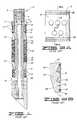
- FIG. 1is a cross-sectional view of a prior art downhole packer apparatus depicting prior art packer show assemblies having the preferred slips and slip assemblies that can be used in connection with the present invention.
- FIG. 2Ais a front view of the preferred slip shown in FIG. 1 that can be used with the present invention.
- FIG. 2Bis a cross-sectional side view of the preferred slip segments shown in FIG. 2A.
- FIG. 2Cis a top view of the preferred slip segments shown in FIGS. 2A and 2B.
- FIG. 3Ais top view of the preferred slip wedge shown in FIG. 1 and can be used with the present invention.
- FIG. 3Bis a cross-sectional side view of the preferred slip wedge shown in FIG. 3A.
- FIG. 3Cis an isolated sectional view of one of the multiple planar surfaces of the slip wedge taken along line 3C as shown in FIG. 3A.
- FIG. 4is a cross-sectional side view of an alternative prior art packer element retainer shoe.
- FIG. 5is a cross-sectional side view of the preferred packer element retainer shoe of the present invention.
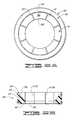
- FIG. 6Ais a top view of the preferred packer shoe and retaining band of the present invention.
- the retaining bandis shown in an exageratedly expanded for clarity.
- FIG. 6Bis a cross-sectional side view of the packer element shoe shown in FIG. 6A.
- FIGS. 1 - 4are all of prior art and have been provided for background and to show the preferred embodiment of a tool in which the present invention is particularly suitable for, but not limited to.
- FIG. 1is a prior art representation of a downhole tool 2 having a mandrel 4.
- the particular tool of FIG. 1is referred to as a bridge plug due to the tool having a plug 6 being pinned within mandrel 4 by radially oriented pins 8.
- Plug 6has a seal means 10 located between plug 6 and the internal diameter of mandrel 4 to prevent fluid flow therebetween.
- the overall tool structureis quite adaptable to tools referred to as packers, which typically have at least one means for allowing fluid communication through the tool.
- packersmay therefore allow for the controlling of fluid passage through the tool by way of a one or more valve mechanisms which may be integral to the packer body or which may be externally attached to the packer body. Such valve mechanisms are not shown in the drawings of the present document.
- the representative toolmay be deployed in wellbores having casings or other such annular structure or geometery in which the tool may be set.
- Tool 2includes the usage of a spacer ring 12 which is preferably secured to mandrel 4 by pins 14.
- Spacer ring 12provides an abutment which serves to axially retain slip segments 18 which are positioned circumferentially about mandrel 4.
- Slip retaining bands 16serve to radially retain slips 18 in an initial circumferential position about mandrel 4 as well as slip wedge 20.
- Bands 16are made of a steel wire, a plastic material, or a composite material having the requisite characteristics of having sufficient strength to hold the slips in place prior to actually setting the tool and to be easily drillable when the tool is to be removed from the wellbore.
- bands 16are inexpensive and easily installed about slip segments 18.
- Slip wedge 20is initially positioned in a slidable relationship to, and partially underneath slip segments 18 as shown in FIG. 1. Slip wedge 20 is shown pinned into place by pins 22. The preferred designs of slip segments 18 and co-acting slip wedges 20 will be described in more detail herein.
- packer element assembly 28Located below slip wedge 20 is at least one packer element, and as shown in FIG. 1, a packer element assembly 28 consisting of three expandable elements positioned about mandrel 4. At both ends of packer element assembly 28 are packer shoes 26 which provide axial support to respective ends of packer element assembly 28. Backup rings 24 which reside against respective upper and lower slip wedges 20 provide structural support to packer shoes 26 when the tool is set within a wellbore.
- the particular packer element arrangement show in FIG. 1is merely representative as there are several packer element arrangements known and used within the art.
- Located below lower slip wedge 20are a plurality of multiple slip segments 18 having at least one retaining band 16 secured thereabout as described earlier.
- lowermost terminating portion of tool 2 referenced as numeral 30is an angled portion referred to as a mule-shoe which is secured to mandrel 4 by radially oriented pins 32.
- lowermost portion 30need not be a mule shoe but could be any type of section which serves to terminate the structure of the tool or serves to be a connector for connecting the tool with other tools, a valve, or tubing etc.
- pins 8, 14, 16, 22, and 32if used at all, are preselected to have shear strengths that allow for the tool be set and to be deployed and to withstand the forces expected to be encountered in a wellbore during the operation of the tool.
- FIG. 5 of the drawingsA broken away cross-sectional view of a tool having a mandrel 49 which has a packer element assembly 29 positioned thereabout, shows a packer shoe 50 embodying the present invention.
- Improved packer shoe 50is preferably made of a phenolic material available from General Plastics, 5727 Ledbetter, Houston, Texas, 77087-4095.
- Other suitable materialsinclude a direction-specific laminate material referred to as GP3581 also available from General Plastics and structural phenolics available from commercial suppliers such as Fiberite, 501 West 3rd Street, Winona, MN 55987.
- Particularly well suited phenolic materials available from Fiberiteinclude, but are not limited to, material designated as FM 4056J and FM 4005.
- each end most section of packer element 29resides directly against shoe 50, which in the preferred embodiment does not employ a backup ring.
- shoe 50preferably has circumferential grooves 54 about the external periphery of shoes 50 for accommodating retaining band 52.
- Retaining band 52serves to secure shoes 50 adjacent each respective end of packer element 29 after the shoes have been initially installed, during transit, and during the running in of the tool into a well bore prior to deploying the tool.
- FIG. 6Ais a view of the preferred non-metallic packer shoe 50 depicted in FIG. 5.
- FIG. 6Bis a cross-sectional view of shoe 50.
- Packer shoe 50preferably has a plurality of individual shoe segments 51 to form a shoe that encircles a mandrel or center section of a downhole tool having a packer element.
- Shoe segments 51preferably include an internal surface 56 which is shaped to accommodate the endmost portion of a packer element thereagainst. Surface 56 is therefore preferably sloped as well as arcuate to provide generally a truncated conical surface which transitions from having a greater radius proximate to external surface 64 to a smaller radius at internal diameter 58.
- the ends of shoe segment 50are defined by surfaces 61 and 62 which are flat and convergent with respect to a center reference point CL which, if the shoe segments were installed about a mandrel, would correspond to the axial centerline of that mandrel as depicted in FIGS. 4 and 5. End surfaces 61 and 62 need not be flat and could be of other topology.
- FIG. 6Aillustrates shoe 50 being made of a total of 8 shoe segments to provide a 360° annulus, or encircling, structure to provide the maximum amount of end support for a packer element that is to be retained in an axial direction.
- a lesser amount, or greater amount of shoes segmentscan be used depending on the nominal diameters of the mandrel, the packer elements, and the wellbore or casing in which the tool is to be deployed.
- Shoe retaining band 52which is shown as being exageratedly expanded and distant from outer external surfaces 64 of shoe 50.
- Shoe retaining band 52is preferably made of a non-metallic material such as composite materials available from General Plastics, 5727 Ledbetter, Houston, Texas, 77087-4095.
- shoe retaining bands 52may alternatively be of a metallic material such as ANSI 1018 steel or any other material having sufficient strength to support and retain the shoes in position prior to actually setting a tool employing such bands.
- retaining bands 50may have either elastic or non-elastic qualities depending on how much radial, and to some extent axial, movement of the shoe segments can be tolerated prior to and during the deployment of the associated tool into a wellbore.
- Shoe 50 as shown in FIG. 6Bhas two retaining bands 52 and respective band accommodating grooves 54.
- Grooves 54are each located proximate to face 60 and proximate to upper most region where outer external surface 64 and arcuate surface 56 intersect, or the distance between the two is at minimum.
- a single band 52appropriately sized and made of a preselected material, can be used.
- a multitude of bands appropriately sized and made of suitable materialcan be used in lieu of the preferred pair of retaining bands 52.
- Testshave been performed using a downhole packer tool, similar to the representative bridge plug tool shown in FIG. 1, having the preferred packer shoe 50 wherein the shoe segments 51 were constructed in accordance with the above description and FIGS. 5 - 6 of the drawings.
- the test segmentswere made of a phenolic material obtained from General Plastics as referenced herein.
- the test toolwas installed in a test chamber and the tool was set and the tool and associated packer elements were then subjected to a maximum differential pressure of 8000 psi (562 Kg/cm 2 ) and a maximum temperature of 250°F ( 120°C).
- a maximum differential pressure8000 psi (562 Kg/cm 2 ) and a maximum temperature of 250°F ( 120°C).
- the segmentshad flared outwardly to and were ultimately restrained by the well bore.
- the subject shoe segmentssuccessfully retained and supported the respective ends of the associated packer elements.
- pressures reaching 10,000 psi (700 Kg/cm 2 ) and temperatures reaching 400° (205°C)are obtainable using shoes embodying the present invention.
- the subject test shoeswere initially retained by a pair of retaining bands as described herein and made of a composite material obtained from General Plastics as referenced herein.
- the associated packer element endswere inspected after the test was performed and found to be in a satisfactory condition with only expected non-catastrophic deformation of the packer element assembly present.
- slip segments 18 and slip wedges 20are prior art, it is preferred that the subject slip segments and slip wedges be constructed as discussed below in order to take full advantage of features and benefits of downhole tools constructed essentially of only non-metallic components as discussed herein.
- packer element shoescan be used in connection with any type of downhole tool employing at least one packer element whether or not the tool is made essentially of only non-metallic components or a combination of metallic and non-metallic components.
- slip segment 18as shown in a front view of the slip segment, denoted as FIG. 2A, has an outer external face 19 in which at least one and preferably a plurality of inserts 34 have been molded into, or otherwise secured into, face 19. Inserts 34 made of zirconia ceramic have been found to be particularly suitable for a wide variety of applications.
- Slip segment 18is preferably made of a composite material obtained from General Plastics as referenced herein in addition to the materials set forth in the present Assignee's patents referenced herein.
- FIG. 2Bis a cross-sectional view taken along line 2B of slip segment of 18 FIG. 2A.
- Slip segment 18has two opposing end sections 21 and 23 and has an arcuate inner mandrel surface 40 having topology which is complementary to the outer most surface of mandrel 4.
- Preferably end section surface 23is angled approximately 5°, shown in FIG. 2B as angle ⁇ , to facilitate outward movement of the slip when setting the tool.
- Slip segment bearing surface 38is flat, or planar, and is specifically designed to have topology matching a complementary surface on slip wedge 20.
- Such matching complementary bearing surface on slip wedge 20is designated as numeral 42 and can be viewed in FIG. 3A of the drawings.
- a top view of slip segment 18, having a flat, but preferably angled, top surface 23is shown in FIG.
- Angle ⁇is preferably approximately equal to 60°. However, an angle of ⁇ ranging from 45° to 60° can be used.
- slip segments 18are designated by numeral 25. It is preferred that six to eight segments encircle mandrel 4 and be retained in place prior to setting of the tool by at least one, and preferably two slip retaining bands 16 that are accommodated by circumferential grooves 36.
- Slip retaining bands 16are made of composite material obtained from General Plastics as referenced herein or other suitable materials such as ANSI 1018 steel wire available from a wide variety of commercial sources.
- slip wedge 20having flat, or planar, surfaces 42 which form an opposing sliding bearing surface to flat bearing surface 38 of respectively positioned slip segments 18.
- the relationship of such surfaces 38 and 42 as installed initiallyare best seen in FIG. 2B, FIG. 3C, and FIG. 1.
- FIG. 3Cwhich is a broken away sectional view taken along line 3C shown in FIG. 3A.
- slip wedge bearing surface 42be defined by guides or barriers 44 to provide a circumferential restraint to slip segments 18 as the segments travel axially along slip wedge 20 and thus radially outwardly toward the casing or well bore during the actual setting of the packer tool.
- angle ⁇as shown in FIG.
- 3Bis approximately 18°. However, other angles ranging from 15° to 20° can be used depending on the frictional resistance between the coacting surfaces 42 and 38 and the forces to be encountered by the slip and slip wedge when set in a well bore.
- Internal bore 46is sized and configured to allow positioning and movement along the outer surface of mandrel 4.
- materialsuch as the composites available from General Plastics are particularly suitable for making a slip wedge 20 from in order to achieve the desired results of providing an easily drillable slip assembly while being able to withstand temperatures and pressures reaching 10,000 psi (700 Kg/cm 2 ) and 425°F ( 220°C). Additionally, suitable material includes the materials set forth herein and in the present Assignee's patents referenced herein.
- a significant advantage of using such co-acting flat or planar bearing surfaces in slip segments 18 and slip wedges 20is that as the slips and wedges slide against each other, the area of contact is maximized, or optimized, as the slip segments axially traverse the slip wedge thereby minimizing the amount of load induced stresses being experienced in the contact area of the slip/slip wedge interface. That is as the slip axially travels along the slip wedge, there is more and more contact surface area available in which to absorb the transmitted loads. This feature reduces or eliminates the possibility of the slips and wedges binding with each other before the slips have ultimately seated against the casing or wellbore. This arrangement is quite different from slips and slip cones using conical surfaces because when using conical bearing surfaces, the contact area is maximized only at one particular slip to slip-cone position.
Landscapes
- Life Sciences & Earth Sciences (AREA)
- Engineering & Computer Science (AREA)
- Geology (AREA)
- Mining & Mineral Resources (AREA)
- Physics & Mathematics (AREA)
- Environmental & Geological Engineering (AREA)
- Fluid Mechanics (AREA)
- General Life Sciences & Earth Sciences (AREA)
- Geochemistry & Mineralogy (AREA)
- Earth Drilling (AREA)
Description
- This invention relates generally to a downhole apparatus for use in awellbore, and particularly but not exclusively to downhole packer and bridgeplug tools.
- In the drilling or reworking of oil wells, a great variety of downholetools are used. For example, but not by way of limitation, it is oftendesirable to seal tubing or other pipe in the casing of the well, such as whenit is desired to pump cement or other slurry down the tubing and force theslurry out into a formation. It then becomes necessary to seal the tubing withrespect to the well casing and to prevent the fluid pressure of the slurry fromlifting the tubing out of the well. Downhole tools referred to as packers andbridge plugs are designed for these general purposes and are well known inthe art of producing oil and gas.
- When it is desired to remove many of these downhole tools from awell bore, it is frequently simpler and less expensive to mill or drill them outrather than to implement a complex retrieving operation. In milling, amilling cutter is used to grind the packer or plug, for example, or at least theouter components thereof, out of the well bore. Milling is a relatively slow process, but when milling with conventional tubular strings, it can be usedon packers or bridge plugs having relatively hard components such aserosion-resistant hard steel. One such packer is disclosed in our U.S. PatentNo. 4,151,875 to Sullaway, and sold under the trademark EZ Disposalpacker.
- In drilling, a drill bit is used to cut and grind up the components of thedownhole tool to remove it from the well bore. This is a much fasteroperation than milling, but requires the tool to be made out of materialswhich can be accommodated by the drill bit. Typically, soft and mediumhardness cast iron are used on the pressure bearing components, along withsome brass and aluminum items. Packers of this type include the HalliburtonEZ Drill® and EZ Drill SV® squeeze packers.
- The EZ Drill SV® squeeze packer, for example, includes a lock ringhousing, upper slip wedge, lower slip wedge, and lower slip support made ofsoft cast iron. These components are mounted on a mandrel made of mediumhardness cast iron. The EZ Drill® squeeze packer is similarly constructed.The Halliburton EZ Drill® bridge plug is also similar, except that it does notprovide for fluid flow therethrough.
- All of the above-mentioned packers are disclosed in HalliburtonServices - Sales and Service Catalog No. 43, pages 2561-2562, and thebridge plug is disclosed in the same catalog on pages 2556-2557.
- The EZ Drill® packer and bridge plug and the EZ Drill SV ® packer aredesigned for fast removal from the well bore by either rotary or cable tool drilling methods. Many of the components inthese drillable packing devices are locked together to preventtheir spinning while being drilled, and the harder slips aregrooved so that they will be broken up in small pieces.Typically, standard "tri-cone" rotary drill bits are used whichare rotated at speeds of about 75 to about 120 rpm. A load ofabout 5,000 to about 7,000 pounds of weight is applied to the bitfor initial drilling and increased as necessary to drill out theremainder of the packer or bridge plug, depending upon its size.Drill collars may be used as required for weight and bitstabilization.
- Such drillable devices have worked well and provide improvedoperating performance at relatively high temperatures andpressures. The packers and bridge plugs mentioned above aredesigned to withstand pressures of about 10,000 psi (700 Kg/cm2)and temperatures of about 425° F (220°C) after being set in thewell bore. Such pressures and temperatures require using the castiron components previously discussed.
- However, drilling out iron components requires certaintechniques. Ideally, the operator employs variations in rotaryspeed and bit weight to help break up the metal parts andreestablish bit penetration should bit penetration cease whiledrilling. A phenomenon known as "bit tracking" can occur, whereinthe drill bit stays on one path and no longer cuts into thedownhole tool. When this happens, it is necessary to pick up thebit above the drilling surface and rapidly recontact the bit withthe packer or plug and apply weight while continuing rotation.This aids in breaking up the established bit pattern and helps to reestablish bit penetration. If this procedure is used, there are rarelyproblems. However, operators may not apply these techniques or evenrecognize when bit tracking has occurred. The result is that drilling timesare greatly increased because the bit merely wears against the surface of thedownhole tool rather than cutting into it to break it up.
- In order to overcome the above long standing problems, we introducedto the industry a line of drillable packers and bridge plugs currentlymarketed under the trademark FAS DRILL. The FAS DRILL line of toolsconsist of a majority of the components being made of non-metallicengineering grade plastics to greatly improve the drillability of suchdownhole tools. The FAS DRILL line of tools have been very successful anda number of U.S. patents have been issued to us including U.S. Patent5,271,468 to Streich et al., U.S. Patent 5,224,540 to Streich et al., and U.S.Patent 5,390,737 to Jacobi et al. Reference should be made to these patentsfor further details.
- Either of US-A-5271468 or US-A-5390737 discloses:
a downhole apparatus for use in a wellbore, which apparatus comprises: - a) a mandrel having an axial centerline;
- b) slip means disposed on the mandrel for grippingly engaging the wellbore when setinto position;
- c) at least one packer element to be axially retained about the mandrel and located at apreselected position along the mandrel defining a packer element assembly; and
- d) at least one packer element retaining shoe, for axially retaining at least one packerelement about the mandrel.
- Notwithstanding the success of the FAS-DRILL line of drillabledownhole packers and bridge plugs, we have discovered that certain metalliccomponents still used within the FAS-DRILL line of packers and bridgeplugs at the time of issuance of the above patents were preventing evenquicker drill out times under certain conditions or when using certainequipment. Exemplary situations include milling with conventional jointedtubulars and in conditions in which normal bit weight or bit speed could notbe obtained. Other exemplary situations include drilling or milling withnon-conventional drilling techniques such as milling or drilling withrelatively flexible coiled tubing.
- When milling or drilling with coiled tubing, which does not provide asignificant amount of weight on the tool being used, even components madeof relatively soft steel, or other metals considered to be low strength, createproblems and increase the amount of time required to mill out or drill out adown hole tool, including such tools as the assignee's FAS DRILL line of drillable non-metallic downhole tools.
- Furthermore, packer shoes and optional back up rings made of ametallic material are employed not so much as a first choice but due to themetallic shoes and back up rings being able to withstand the temperaturesand pressures typically encountered by a downhole tool deployed in aborehole.
- Another shortcoming with using metallic packer shoes and optionalbackup rings is that upon deployment of the tool, the typically brass packershoe may not flare outwardly as the packer portion is being compressed andtherefore not expand outwardly as desired. If the brass shoe does notproperly flare, it can lead to unwanted severe distortion of the shoes andsubsequent cutting of the packer element which reduces its ability to hold toits rated differential pressure or lead to a complete failure of the tool.
- We have now devised a downhole apparatus whereby these and othershortcomings can be reduced, or eliminated.
- According to the present invention, there is provided a downholeapparatus for use in a wellbore, which apparatus comprises:
- a) a mandrel having an axial centerline;
- b) slip means disposed on the mandrel for grippingly engaging thewellbore when set into position;
- c) at least one packer element to be axially retained about the mandreland located at a preselected position along the mandrel defining apacker element assembly; and
- d) at least one packer element retaining shoe made of a non-metallicmaterial for axially retaining the at least one packer element about themandrel, the said shoe comprising a plurality of shoe segments andhaving means for retaining the segments in an initial position aboutthe mandrel.
- The downhole tool apparatus of the present invention preferablyutilizes essentially all non-metallic materials, such as engineering grade plastics, resins, or composites, to reduceweight which facilitates and reduces shipping expenses, to reducemanufacturing time and labor, to improve performance throughreducing frictional forces of sliding surfaces, to reduce costsand to improve drillability of the apparatus when drilling isrequired to remove the apparatus from the well bore. Primarily,in this disclosure, the downhole tool is characterized by a wellbore packing apparatus, but it is not intended that the inventionbe limited to specific embodiments of such packing devices. Theuse of essentially only non-metallic components in the downholetool apparatus allows for and increases the efficiency ofalternative drilling and milling techniques in addition toconventional drilling and milling techniques.
- In packing apparatus embodiments of the present invention,the apparatus may utilize the same general geometric configurationof previously known drillable non-metallic packers and bridgeplugs such as those disclosed in U.S. Patents 5,271,468 to Streichet al., U.S. Patent 5,224,540 to Streich et al., and U.S. Patent5,390,737 to Jacobi et al. while replacing essentially all of thefew remaining metal components of the tools disclosed in thepreceding patents with non-metallic materials which can stillwithstand the pressures and temperatures found in many well boreapplications. In other embodiments of the present invention, theapparatus may comprise specific design changes to accommodate theadvantages of using essentially only plastic and compositematerials and to allow for the reduced strengths thereof comparedto metal components.
- In a preferred embodiment of the downhole tool, the invention comprises a center mandrel and slip means disposed on the mandrelfor grippingly engaging the well bore when in a set position. Theapparatus further comprises a packing means disposed on themandrel for sealingly engaging the well bore when in a setposition.
- The slip means comprises a slip wedge positioned around thecenter mandrel, a plurality of slip segments disposed in aninitial position around the mandrel and adjacent to the slipwedge, retaining means for holding the slip segments in an initialposition. In the preferred embodiment, the slip means utilizesseparate slip segments. The retaining means is characterized byat least one retaining band extending at least partially aroundthe slips. In another embodiment, the retaining means ischaracterized by a ring portion integrally formed with the slips.This ring portion is fracturable during a setting operation,whereby the slips are separated so that they can be moved intogripping engagement with the well bore. Hardened inserts may bemolded into the slips. The inserts may be metallic, such ashardened steel, or non-metallic, such as a ceramic material.
- In the preferred embodiment, the slip means includes a slipwedge installed on the mandrel and the slip segments, whetherretained by a retaining band or whether retained by an integralring portion, have coacting planar, or flat portions, whichprovide a superior sliding bearing surface especially when theslip means are made of a non-metallic material such as engineeringgrade plastics, resins, phenolics, or composites.
- Also in the preferred embodiment of applicant's presentinvention, prior art packer element shoes and back up ring, such as those referred to as
elements - In order that the invention may be more fully understood, variousembodiments thereof will now be described, by way of example only, withreference to the accompanying drawings, wherein:
- FIG. 1 is a cross-sectional view of a prior art downhole packerapparatus depicting prior art packer show assemblies having the preferredslips and slip assemblies that can be used in connection with the presentinvention.
- FIG. 2A is a front view of the preferred slip shown in FIG. 1 that canbe used with the present invention.
- FIG. 2B is a cross-sectional side view of the preferred slip segmentsshown in FIG. 2A.
- FIG. 2C is a top view of the preferred slip segments shown in FIGS.2A and 2B.
- FIG. 3A is top view of the preferred slip wedge shown in FIG.1 and can be used with the present invention.
- FIG. 3B is a cross-sectional side view of the preferred slipwedge shown in FIG. 3A.
- FIG. 3C is an isolated sectional view of one of the multipleplanar surfaces of the slip wedge taken along
line 3C as shown inFIG. 3A. - FIG. 4 is a cross-sectional side view of an alternative priorart packer element retainer shoe.
- FIG. 5 is a cross-sectional side view of the preferred packerelement retainer shoe of the present invention.
- FIG. 6A is a top view of the preferred packer shoe andretaining band of the present invention. The retaining band isshown in an exageratedly expanded for clarity.
- FIG. 6B is a cross-sectional side view of the packer elementshoe shown in FIG. 6A.
- Referring now to the drawings. FIGS. 1 - 4 are all of priorart and have been provided for background and to show thepreferred embodiment of a tool in which the present invention isparticularly suitable for, but not limited to.
- FIG. 1 is a prior art representation of a
downhole tool 2having a mandrel 4. The particular tool of FIG. 1 is referred toas a bridge plug due to the tool having a plug 6 being pinnedwithin mandrel 4 by radially oriented pins 8. Plug 6 has a sealmeans 10 located between plug 6 and the internal diameter ofmandrel 4 to prevent fluid flow therebetween. The overall toolstructure, however, is quite adaptable to tools referred to as packers, which typically have at least one means for allowingfluid communication through the tool. Packers may therefore allowfor the controlling of fluid passage through the tool by way ofa one or more valve mechanisms which may be integral to the packerbody or which may be externally attached to the packer body. Suchvalve mechanisms are not shown in the drawings of the presentdocument. The representative tool may be deployed in wellboreshaving casings or other such annular structure or geometery inwhich the tool may be set. Tool 2 includes the usage of aspacer ring 12 which ispreferably secured to mandrel 4 by pins 14.Spacer ring 12provides an abutment which serves to axially retainslip segments 18 which are positioned circumferentially about mandrel 4. Slipretainingbands 16 serve to radially retain slips 18 in an initialcircumferential position about mandrel 4 as well asslip wedge 20.Bands 16 are made of a steel wire, a plastic material, or acomposite material having the requisite characteristics of havingsufficient strength to hold the slips in place prior to actuallysetting the tool and to be easily drillable when the tool is tobe removed from the wellbore. Preferablybands 16 are inexpensiveand easily installed aboutslip segments 18. Slipwedge 20 isinitially positioned in a slidable relationship to, and partiallyunderneathslip segments 18 as shown in FIG. 1. Slipwedge 20 isshown pinned into place by pins 22. The preferred designs ofslipsegments 18 andco-acting slip wedges 20 will be described in moredetail herein.- Located below
slip wedge 20 is at least one packer element,and as shown in FIG. 1, apacker element assembly 28 consisting of three expandable elements positioned about mandrel 4. At bothends ofpacker element assembly 28 arepacker shoes 26 whichprovide axial support to respective ends ofpacker elementassembly 28. Backup rings 24 which reside against respectiveupper andlower slip wedges 20 provide structural support topacker shoes 26 when the tool is set within a wellbore. Theparticular packer element arrangement show in FIG. 1 is merelyrepresentative as there are several packer element arrangementsknown and used within the art. - Located below
lower slip wedge 20 are a plurality ofmultipleslip segments 18 having at least one retainingband 16 securedthereabout as described earlier. - At the lowermost terminating portion of
tool 2 referenced asnumeral 30 is an angled portion referred to as a mule-shoe whichis secured to mandrel 4 by radially oriented pins 32. Howeverlowermost portion 30 need not be a mule shoe but could be any typeof section which serves to terminate the structure of the tool orserves to be a connector for connecting the tool with other tools,a valve, or tubing etc. It should be appreciated by those in theart, that pins 8, 14, 16, 22, and 32, if used at all, arepreselected to have shear strengths that allow for the tool be setand to be deployed and to withstand the forces expected to beencountered in a wellbore during the operation of the tool. - As described in the patents referenced herein, the majorityof the components in
tool 2 of FIG. 1, with the exception ofpacker shoes 26 and back up rings 24, are made of a non-metallicmaterial. Prior to the present invention, the use of metallicpacker shoes and back up rings were required to be used in the Assignee's line of FAS DRILL downhole tool line because of thelack of a suitable non-metallic material being known or availablethat could withstand the pressures and temperatures typicallyencountered in a well-bore in which the tool was to be deployed.Additionally, a downhole tool having apacker element assembly 29positioned about amandrel 49 as shown in the broken away cross-sectionalview of FIG. 4, it is known within the art that ametallic packer element back upshoe 25 not having a back up ringto provide additional support to the shoe can be used in certaincircumstances. However, a single metallic shoe, such asshoe 25of prior art FIG. 4, can nonetheless cause problems upon millingor drilling out the tool due to the drill and mill resistantnature of the metallic material of a prior art single shoe,especially when non-conventional milling or drilling techniquesare being used. - Referring now to FIG. 5 of the drawings. A broken awaycross-sectional view of a tool having a
mandrel 49 which has apacker element assembly 29 positioned thereabout, shows apackershoe 50 embodying the present invention.Improved packer shoe 50is preferably made of a phenolic material available from GeneralPlastics, 5727 Ledbetter, Houston, Texas, 77087-4095. Othersuitable materials include a direction-specific laminate materialreferred to as GP3581 also available from General Plastics andstructural phenolics available from commercial suppliers such asFiberite, 501 West 3rd Street, Winona, MN 55987. Particularlywell suited phenolic materials available from Fiberite include,but are not limited to, material designated as FM 4056J and FM4005. - As can be seen in FIG. 5, each end most section of
packerelement 29 resides directly againstshoe 50, which in thepreferred embodiment does not employ a backup ring. Eachshoe 50preferably hascircumferential grooves 54 about the externalperiphery ofshoes 50 for accommodating retainingband 52.Retainingband 52 serves to secureshoes 50 adjacent eachrespective end ofpacker element 29 after the shoes have beeninitially installed, during transit, and during the running in ofthe tool into a well bore prior to deploying the tool. - Referring to FIG. 6A which is a view of the preferred
non-metallicpacker shoe 50 depicted in FIG. 5. FIG. 6B is a cross-sectionalview ofshoe 50.Packer shoe 50 preferably has aplurality ofindividual shoe segments 51 to form a shoe thatencircles a mandrel or center section of a downhole tool havinga packer element.Shoe segments 51 preferably include aninternalsurface 56 which is shaped to accommodate the endmost portion ofa packer element thereagainst.Surface 56 is therefore preferablysloped as well as arcuate to provide generally a truncated conicalsurface which transitions from having a greater radius proximatetoexternal surface 64 to a smaller radius atinternal diameter 58. The ends ofshoe segment 50 are defined bysurfaces - FIG. 6A illustrates
shoe 50 being made of a total of 8shoe segments to provide a 360° annulus, or encircling, structure to provide the maximum amount of end support for a packer elementthat is to be retained in an axial direction. A lesser amount,or greater amount of shoes segments can be used depending on thenominal diameters of the mandrel, the packer elements, and thewellbore or casing in which the tool is to be deployed. Shoe retaining band 52, which is shown as being exageratedlyexpanded and distant from outerexternal surfaces 64 ofshoe 50.Shoe retaining band 52 is preferably made of a non-metallicmaterial such as composite materials available from GeneralPlastics, 5727 Ledbetter, Houston, Texas, 77087-4095. However,shoe retaining bands 52 may alternatively be of a metallicmaterial such as ANSI 1018 steel or any other material havingsufficient strength to support and retain the shoes in positionprior to actually setting a tool employing such bands.Furthermore, retainingbands 50 may have either elastic or non-elasticqualities depending on how much radial, and to some extentaxial, movement of the shoe segments can be tolerated prior to andduring the deployment of the associated tool into a wellbore.Shoe 50 as shown in FIG. 6B has two retainingbands 52 andrespectiveband accommodating grooves 54.Grooves 54 are eachlocated proximate to face 60 and proximate to upper most regionwhere outerexternal surface 64 andarcuate surface 56 intersect,or the distance between the two is at minimum. As discussedearlier, asingle band 52, appropriately sized and made of apreselected material, can be used. Alternatively, a multitude ofbands appropriately sized and made of suitable material can beused in lieu of the preferred pair of retainingbands 52.- Tests have been performed using a downhole packer tool, similar to the representative bridge plug tool shown in FIG. 1,having the preferred
packer shoe 50 wherein theshoe segments 51were constructed in accordance with the above description andFIGS. 5 - 6 of the drawings. The test segments were made of aphenolic material obtained from General Plastics as referencedherein. - The test tool was installed in a test chamber and the toolwas set and the tool and associated packer elements were thensubjected to a maximum differential pressure of 8000 psi (562Kg/cm2) and a maximum temperature of 250°F ( 120°C). Uponinspection of the subject shoe segments after the test, thesegments had flared outwardly to and were ultimately restrainedby the well bore. The subject shoe segments successfully retainedand supported the respective ends of the associated packerelements. Thus it is fully expected that pressures reaching10,000 psi (700 Kg/cm2) and temperatures reaching 400° (205°C) areobtainable using shoes embodying the present invention. Thesubject test shoes were initially retained by a pair of retainingbands as described herein and made of a composite materialobtained from General Plastics as referenced herein. Theassociated packer element ends were inspected after the test wasperformed and found to be in a satisfactory condition with onlyexpected non-catastrophic deformation of the packer elementassembly present.
- Returning now to FIGS. 2 - 4 of the drawings. Although, itis admitted that
slip segments 18 and slipwedges 20 are priorart, it is preferred that the subject slip segments and slipwedges be constructed as discussed below in order to take full advantage of features and benefits of downhole tools constructedessentially of only non-metallic components as discussed herein. - However, it is not necessary to have the particular slipsegment and slip wedge construction shown in FIGS. 2 - 4 in orderto practice the present invention, as the disclosed packer elementshoes can be used in connection with any type of downhole toolemploying at least one packer element whether or not the tool ismade essentially of only non-metallic components or a combinationof metallic and non-metallic components.
- Preferably,
slip segment 18 as shown in a front view of theslip segment, denoted as FIG. 2A, has an outerexternal face 19in which at least one and preferably a plurality ofinserts 34have been molded into, or otherwise secured into,face 19.Inserts 34 made of zirconia ceramic have been found to beparticularly suitable for a wide variety of applications.Slipsegment 18 is preferably made of a composite material obtainedfrom General Plastics as referenced herein in addition to thematerials set forth in the present Assignee's patents referencedherein. - FIG. 2B is a cross-sectional view taken along line 2B of slipsegment of 18 FIG. 2A.
Slip segment 18 has twoopposing endsections inner mandrel surface 40having topology which is complementary to the outer most surfaceof mandrel 4. Preferably endsection surface 23 is angledapproximately 5°, shown in FIG. 2B as angle , to facilitateoutward movement of the slip when setting the tool. Slipsegmentbearing surface 38 is flat, or planar, and is specificallydesigned to have topology matching a complementary surface onslip wedge 20. Such matching complementary bearing surface onslipwedge 20 is designated asnumeral 42 and can be viewed in FIG. 3Aof the drawings. A top view ofslip segment 18, having a flat,but preferably angled,top surface 23 is shown in FIG. 2C.Location and the radial positioning ofsides 25 define an angleα which is preselected to achieve an optimal number of segmentsfor a mandrel having an outside diameter of a given size and forthe casing or well bore diameter in which the tool is to be set.Angle α is preferably approximately equal to 60°. However, anangle of α ranging from 45° to 60° can be used. - Returning to FIG. 2B, the sides of
slip segments 18 aredesignated bynumeral 25. It is preferred that six to eightsegments encircle mandrel 4 and be retained in place prior tosetting of the tool by at least one, and preferably twoslipretaining bands 16 that are accommodated bycircumferentialgrooves 36. Slip retainingbands 16 are made of compositematerial obtained from General Plastics as referenced herein orother suitable materials such as ANSI 1018 steel wire availablefrom a wide variety of commercial sources. - Referring to FIG. 3A, a top view is provided of
preferredslip wedge 20 having flat, or planar, surfaces 42 which form anopposing sliding bearing surface toflat bearing surface 38 ofrespectively positionedslip segments 18. The relationship ofsuch surfaces line 3C shown in FIG.3A. It is preferred that slipwedge bearing surface 42 be definedby guides orbarriers 44 to provide a circumferential restraint to slipsegments 18 as the segments travel axially alongslipwedge 20 and thus radially outwardly toward the casing or wellbore during the actual setting of the packer tool. Preferablyangle β, as shown in FIG. 3B is approximately 18°. However, otherangles ranging from 15° to 20° can be used depending on thefrictional resistance between the coacting surfaces 42 and 38 andthe forces to be encountered by the slip and slip wedge when setin a well bore. Internal bore 46 is sized and configured to allowpositioning and movement along the outer surface of mandrel 4. - It has been found that material such as the compositesavailable from General Plastics are particularly suitable formaking a
slip wedge 20 from in order to achieve the desiredresults of providing an easily drillable slip assembly while beingable to withstand temperatures and pressures reaching 10,000 psi(700 Kg/cm2) and 425°F ( 220°C). Additionally, suitable materialincludes the materials set forth herein and in the presentAssignee's patents referenced herein. - A significant advantage of using such co-acting flat orplanar bearing surfaces in
slip segments 18 and slipwedges 20 isthat as the slips and wedges slide against each other, the areaof contact is maximized, or optimized, as the slip segmentsaxially traverse the slip wedge thereby minimizing the amount ofload induced stresses being experienced in the contact area of theslip/slip wedge interface. That is as the slip axially travelsalong the slip wedge, there is more and more contact surface areaavailable in which to absorb the transmitted loads. This featurereduces or eliminates the possibility of the slips and wedgesbinding with each other before the slips have ultimately seated against the casing or wellbore. This arrangement is quitedifferent from slips and slip cones using conical surfaces becausewhen using conical bearing surfaces, the contact area is maximizedonly at one particular slip to slip-cone position. - The practical operation of downhole tools embodying thepresent invention, including the representative tool depicted anddescribed herein, is conventional and thus known in the art asevidenced by prior documents.
- Furthermore, although the disclosed invention has been shownand described in detail with respect to the preferred embodiment,it will be understood by those skilled in the art that variouschanges in the form and detail thereof may be made.
Claims (10)
- A downhole apparatus for use in a wellbore, which apparatuscomprises:a) a mandrel (49) having an axial centerline;b) slip means (20) disposed on the mandrel for grippingly engagingthe wellbore when set into position;c) at least one packer element (29) to be axially retained about themandrel and located at a preselected position along the mandreldefining a packer element assembly; andd) at least one packer element retaining shoe (50) made of a non-metallicmaterial for axially retaining the at least one packerelement about the mandrel, the said shoe comprising a pluralityof show segments (51) and having means (52) for retaining thesegments in an initial position about the mandrel.
- Apparatus according to claim 1, wherein at least a portion of theretaining shoe (50) is made of a phenolic material.
- Apparatus according to claim 2, wherein at least one of the shoesegments (51) is made of a phenolic material.
- Apparatus according to claim 1, 2 or 3, wherein at least one of theshoe segments (51) is made of a laminated non-metallic composite material.
- Apparatus according to claim 1, 2, 3 or 4, wherein the shoe retainingmeans comprises at least one retaining band (52) made of a non-metalliccomposite material.
- Apparatus according to any of claims 1 to 5, wherein at least one shoesegment has an external face having at least one groove (54) therein toaccommodate at least one retaining band.
- Apparatus according to any of claims 1 to 6, wherein the mandrel, andat least a portion of the slip means, is made of a non-metallic material.
- Apparatus according to claim 7, wherein the mandrel is made of a non-metalliccomposite and the slip means is made at least partially of a non-metalliccomposite.
- Apparatus according to any of claims 1 to 8, wherein the slip meanscomprises a plurality of slip segments and an associated slip wedge beinglocated proximate to an end most portion of a packer element assembly, eachof the slip segments having a planar bearing surface and the associated slipwedge having a corresponding planar bearing surface for the planar bearingsurface of each slip segment.
- Apparatus according to claim 9, wherein the planar bearing surfaces ofthe slip segments and the slip wedge are inclined at an angle between 15°and 20°, preferably approximately 18°, with respect to the axial centerlineof the mandrel.
Applications Claiming Priority (2)
| Application Number | Priority Date | Filing Date | Title |
|---|---|---|---|
| US08/442,448US5540279A (en) | 1995-05-16 | 1995-05-16 | Downhole tool apparatus with non-metallic packer element retaining shoes |
| US442448 | 1995-05-16 |
Publications (3)
| Publication Number | Publication Date |
|---|---|
| EP0743422A2 EP0743422A2 (en) | 1996-11-20 |
| EP0743422A3 EP0743422A3 (en) | 1998-02-18 |
| EP0743422B1true EP0743422B1 (en) | 2001-11-28 |
Family
ID=23756824
Family Applications (1)
| Application Number | Title | Priority Date | Filing Date |
|---|---|---|---|
| EP96303392AExpired - LifetimeEP0743422B1 (en) | 1995-05-16 | 1996-05-14 | Downhole packing assembly |
Country Status (4)
| Country | Link |
|---|---|
| US (1) | US5540279A (en) |
| EP (1) | EP0743422B1 (en) |
| CA (1) | CA2176669C (en) |
| DE (1) | DE69617312T2 (en) |
Families Citing this family (139)
| Publication number | Priority date | Publication date | Assignee | Title |
|---|---|---|---|---|
| US7147068B2 (en) | 1994-10-14 | 2006-12-12 | Weatherford / Lamb, Inc. | Methods and apparatus for cementing drill strings in place for one pass drilling and completion of oil and gas wells |
| US7108084B2 (en) | 1994-10-14 | 2006-09-19 | Weatherford/Lamb, Inc. | Methods and apparatus for cementing drill strings in place for one pass drilling and completion of oil and gas wells |
| US6868906B1 (en) | 1994-10-14 | 2005-03-22 | Weatherford/Lamb, Inc. | Closed-loop conveyance systems for well servicing |
| US7100710B2 (en) | 1994-10-14 | 2006-09-05 | Weatherford/Lamb, Inc. | Methods and apparatus for cementing drill strings in place for one pass drilling and completion of oil and gas wells |
| US7228901B2 (en) | 1994-10-14 | 2007-06-12 | Weatherford/Lamb, Inc. | Method and apparatus for cementing drill strings in place for one pass drilling and completion of oil and gas wells |
| US7036610B1 (en) | 1994-10-14 | 2006-05-02 | Weatherford / Lamb, Inc. | Apparatus and method for completing oil and gas wells |
| US7013997B2 (en) | 1994-10-14 | 2006-03-21 | Weatherford/Lamb, Inc. | Methods and apparatus for cementing drill strings in place for one pass drilling and completion of oil and gas wells |
| US7040420B2 (en) | 1994-10-14 | 2006-05-09 | Weatherford/Lamb, Inc. | Methods and apparatus for cementing drill strings in place for one pass drilling and completion of oil and gas wells |
| US5701959A (en)* | 1996-03-29 | 1997-12-30 | Halliburton Company | Downhole tool apparatus and method of limiting packer element extrusion |
| US5839515A (en)* | 1997-07-07 | 1998-11-24 | Halliburton Energy Services, Inc. | Slip retaining system for downhole tools |
| US7509722B2 (en) | 1997-09-02 | 2009-03-31 | Weatherford/Lamb, Inc. | Positioning and spinning device |
| US6742596B2 (en) | 2001-05-17 | 2004-06-01 | Weatherford/Lamb, Inc. | Apparatus and methods for tubular makeup interlock |
| US6536520B1 (en) | 2000-04-17 | 2003-03-25 | Weatherford/Lamb, Inc. | Top drive casing system |
| US5984007A (en)* | 1998-01-09 | 1999-11-16 | Halliburton Energy Services, Inc. | Chip resistant buttons for downhole tools having slip elements |
| US6167963B1 (en) | 1998-05-08 | 2001-01-02 | Baker Hughes Incorporated | Removable non-metallic bridge plug or packer |
| GB9815809D0 (en) | 1998-07-22 | 1998-09-16 | Appleton Robert P | Casing running tool |
| GB2340859A (en) | 1998-08-24 | 2000-03-01 | Weatherford Lamb | Method and apparatus for facilitating the connection of tubulars using a top drive |
| GB2340857A (en) | 1998-08-24 | 2000-03-01 | Weatherford Lamb | An apparatus for facilitating the connection of tubulars and alignment with a top drive |
| GB2340858A (en) | 1998-08-24 | 2000-03-01 | Weatherford Lamb | Methods and apparatus for facilitating the connection of tubulars using a top drive |
| US7188687B2 (en) | 1998-12-22 | 2007-03-13 | Weatherford/Lamb, Inc. | Downhole filter |
| AU772327B2 (en) | 1998-12-22 | 2004-04-22 | Weatherford Technology Holdings, Llc | Procedures and equipment for profiling and jointing of pipes |
| GB2345074A (en) | 1998-12-24 | 2000-06-28 | Weatherford Lamb | Floating joint to facilitate the connection of tubulars using a top drive |
| GB2347441B (en) | 1998-12-24 | 2003-03-05 | Weatherford Lamb | Apparatus and method for facilitating the connection of tubulars using a top drive |
| US7311148B2 (en) | 1999-02-25 | 2007-12-25 | Weatherford/Lamb, Inc. | Methods and apparatus for wellbore construction and completion |
| US6857487B2 (en) | 2002-12-30 | 2005-02-22 | Weatherford/Lamb, Inc. | Drilling with concentric strings of casing |
| US6896075B2 (en) | 2002-10-11 | 2005-05-24 | Weatherford/Lamb, Inc. | Apparatus and methods for drilling with casing |
| US7216727B2 (en) | 1999-12-22 | 2007-05-15 | Weatherford/Lamb, Inc. | Drilling bit for drilling while running casing |
| US7334650B2 (en) | 2000-04-13 | 2008-02-26 | Weatherford/Lamb, Inc. | Apparatus and methods for drilling a wellbore using casing |
| US7325610B2 (en) | 2000-04-17 | 2008-02-05 | Weatherford/Lamb, Inc. | Methods and apparatus for handling and drilling with tubulars or casing |
| GB0010378D0 (en) | 2000-04-28 | 2000-06-14 | Bbl Downhole Tools Ltd | Expandable apparatus for drift and reaming a borehole |
| US7600572B2 (en)* | 2000-06-30 | 2009-10-13 | Bj Services Company | Drillable bridge plug |
| US7255178B2 (en)* | 2000-06-30 | 2007-08-14 | Bj Services Company | Drillable bridge plug |
| US6578633B2 (en) | 2000-06-30 | 2003-06-17 | Bj Services Company | Drillable bridge plug |
| US6491108B1 (en) | 2000-06-30 | 2002-12-10 | Bj Services Company | Drillable bridge plug |
| US6394180B1 (en) | 2000-07-12 | 2002-05-28 | Halliburton Energy Service,S Inc. | Frac plug with caged ball |
| GB2365463B (en)* | 2000-08-01 | 2005-02-16 | Renovus Ltd | Drilling method |
| US6712153B2 (en)* | 2001-06-27 | 2004-03-30 | Weatherford/Lamb, Inc. | Resin impregnated continuous fiber plug with non-metallic element system |
| CA2396242C (en) | 2001-08-20 | 2008-10-07 | Halliburton Energy Services, Inc. | Expandable retaining shoe |
| US20040007829A1 (en)* | 2001-09-07 | 2004-01-15 | Ross Colby M. | Downhole seal assembly and method for use of same |
| US7216700B2 (en)* | 2001-09-17 | 2007-05-15 | Smith International, Inc. | Torsional resistant slip mechanism and method |
| GB0206227D0 (en) | 2002-03-16 | 2002-05-01 | Weatherford Lamb | Bore-lining and drilling |
| US6769491B2 (en)* | 2002-06-07 | 2004-08-03 | Weatherford/Lamb, Inc. | Anchoring and sealing system for a downhole tool |
| US6695050B2 (en)* | 2002-06-10 | 2004-02-24 | Halliburton Energy Services, Inc. | Expandable retaining shoe |
| US6695051B2 (en) | 2002-06-10 | 2004-02-24 | Halliburton Energy Services, Inc. | Expandable retaining shoe |
| US6796376B2 (en)* | 2002-07-02 | 2004-09-28 | Warren L. Frazier | Composite bridge plug system |
| US6994176B2 (en) | 2002-07-29 | 2006-02-07 | Weatherford/Lamb, Inc. | Adjustable rotating guides for spider or elevator |
| US7730965B2 (en) | 2002-12-13 | 2010-06-08 | Weatherford/Lamb, Inc. | Retractable joint and cementing shoe for use in completing a wellbore |
| US6899186B2 (en) | 2002-12-13 | 2005-05-31 | Weatherford/Lamb, Inc. | Apparatus and method of drilling with casing |
| US7048066B2 (en)* | 2002-10-09 | 2006-05-23 | Halliburton Energy Services, Inc. | Downhole sealing tools and method of use |
| US6966386B2 (en)* | 2002-10-09 | 2005-11-22 | Halliburton Energy Services, Inc. | Downhole sealing tools and method of use |
| US7303022B2 (en) | 2002-10-11 | 2007-12-04 | Weatherford/Lamb, Inc. | Wired casing |
| US7234522B2 (en) | 2002-12-18 | 2007-06-26 | Halliburton Energy Services, Inc. | Apparatus and method for drilling a wellbore with casing and cementing the casing in the wellbore |
| US7128154B2 (en)* | 2003-01-30 | 2006-10-31 | Weatherford/Lamb, Inc. | Single-direction cementing plug |
| USRE42877E1 (en) | 2003-02-07 | 2011-11-01 | Weatherford/Lamb, Inc. | Methods and apparatus for wellbore construction and completion |
| CA2516649C (en) | 2003-02-27 | 2010-01-19 | Weatherford/Lamb, Inc. | Drill shoe |
| GB2415722B (en) | 2003-03-05 | 2007-12-05 | Weatherford Lamb | Casing running and drilling system |
| US7503397B2 (en) | 2004-07-30 | 2009-03-17 | Weatherford/Lamb, Inc. | Apparatus and methods of setting and retrieving casing with drilling latch and bottom hole assembly |
| WO2004079147A2 (en) | 2003-03-05 | 2004-09-16 | Weatherford/Lamb, Inc. | Method and apparatus for drilling with casing |
| CA2517978C (en) | 2003-03-05 | 2009-07-14 | Weatherford/Lamb, Inc. | Drilling with casing latch |
| CA2517883C (en) | 2003-03-05 | 2010-01-12 | Weatherford/Lamb, Inc. | Full bore lined wellbores |
| WO2004090279A1 (en) | 2003-04-04 | 2004-10-21 | Weatherford/Lamb, Inc. | Method and apparatus for handling wellbore tubulars |
| US20040231845A1 (en) | 2003-05-15 | 2004-11-25 | Cooke Claude E. | Applications of degradable polymers in wells |
| US20090107684A1 (en) | 2007-10-31 | 2009-04-30 | Cooke Jr Claude E | Applications of degradable polymers for delayed mechanical changes in wells |
| US7650944B1 (en) | 2003-07-11 | 2010-01-26 | Weatherford/Lamb, Inc. | Vessel for well intervention |
| US7036602B2 (en) | 2003-07-14 | 2006-05-02 | Weatherford/Lamb, Inc. | Retrievable bridge plug |
| US6976534B2 (en)* | 2003-09-29 | 2005-12-20 | Halliburton Energy Services, Inc. | Slip element for use with a downhole tool and a method of manufacturing same |
| US7264067B2 (en) | 2003-10-03 | 2007-09-04 | Weatherford/Lamb, Inc. | Method of drilling and completing multiple wellbores inside a single caisson |
| US7210533B2 (en) | 2004-02-11 | 2007-05-01 | Halliburton Energy Services, Inc. | Disposable downhole tool with segmented compression element and method |
| US7353879B2 (en)* | 2004-03-18 | 2008-04-08 | Halliburton Energy Services, Inc. | Biodegradable downhole tools |
| US7093664B2 (en)* | 2004-03-18 | 2006-08-22 | Halliburton Energy Services, Inc. | One-time use composite tool formed of fibers and a biodegradable resin |
| US7168494B2 (en)* | 2004-03-18 | 2007-01-30 | Halliburton Energy Services, Inc. | Dissolvable downhole tools |
| US7163066B2 (en)* | 2004-05-07 | 2007-01-16 | Bj Services Company | Gravity valve for a downhole tool |
| US7284617B2 (en) | 2004-05-20 | 2007-10-23 | Weatherford/Lamb, Inc. | Casing running head |
| GB2424432B (en) | 2005-02-28 | 2010-03-17 | Weatherford Lamb | Deep water drilling with casing |
| CA2628164C (en)* | 2005-11-10 | 2011-02-22 | Bj Services Company | Self centralizing non-rotational slip and cone system for downhole tools |
| GB2451784B (en) | 2006-05-12 | 2011-06-01 | Weatherford Lamb | Stage cementing methods used in casing while drilling |
| US8276689B2 (en) | 2006-05-22 | 2012-10-02 | Weatherford/Lamb, Inc. | Methods and apparatus for drilling with casing |
| US7661481B2 (en)* | 2006-06-06 | 2010-02-16 | Halliburton Energy Services, Inc. | Downhole wellbore tools having deteriorable and water-swellable components thereof and methods of use |
| US20070284114A1 (en) | 2006-06-08 | 2007-12-13 | Halliburton Energy Services, Inc. | Method for removing a consumable downhole tool |
| US20080257549A1 (en) | 2006-06-08 | 2008-10-23 | Halliburton Energy Services, Inc. | Consumable Downhole Tools |
| US7591318B2 (en) | 2006-07-20 | 2009-09-22 | Halliburton Energy Services, Inc. | Method for removing a sealing plug from a well |
| US7373973B2 (en)* | 2006-09-13 | 2008-05-20 | Halliburton Energy Services, Inc. | Packer element retaining system |
| US7762323B2 (en)* | 2006-09-25 | 2010-07-27 | W. Lynn Frazier | Composite cement retainer |
| GB2444060B (en) | 2006-11-21 | 2008-12-17 | Swelltec Ltd | Downhole apparatus and method |
| US20080202764A1 (en)* | 2007-02-22 | 2008-08-28 | Halliburton Energy Services, Inc. | Consumable downhole tools |
| US7735549B1 (en) | 2007-05-03 | 2010-06-15 | Itt Manufacturing Enterprises, Inc. | Drillable down hole tool |
| US20090038790A1 (en)* | 2007-08-09 | 2009-02-12 | Halliburton Energy Services, Inc. | Downhole tool with slip elements having a friction surface |
| US7740079B2 (en)* | 2007-08-16 | 2010-06-22 | Halliburton Energy Services, Inc. | Fracturing plug convertible to a bridge plug |
| US7708066B2 (en)* | 2007-12-21 | 2010-05-04 | Frazier W Lynn | Full bore valve for downhole use |
| US8235102B1 (en) | 2008-03-26 | 2012-08-07 | Robertson Intellectual Properties, LLC | Consumable downhole tool |
| US8327926B2 (en) | 2008-03-26 | 2012-12-11 | Robertson Intellectual Properties, LLC | Method for removing a consumable downhole tool |
| US7779906B2 (en)* | 2008-07-09 | 2010-08-24 | Halliburton Energy Services, Inc. | Downhole tool with multiple material retaining ring |
| US8267177B1 (en) | 2008-08-15 | 2012-09-18 | Exelis Inc. | Means for creating field configurable bridge, fracture or soluble insert plugs |
| US7900696B1 (en) | 2008-08-15 | 2011-03-08 | Itt Manufacturing Enterprises, Inc. | Downhole tool with exposable and openable flow-back vents |
| US9217319B2 (en) | 2012-05-18 | 2015-12-22 | Frazier Technologies, L.L.C. | High-molecular-weight polyglycolides for hydrocarbon recovery |
| US9587475B2 (en) | 2008-12-23 | 2017-03-07 | Frazier Ball Invention, LLC | Downhole tools having non-toxic degradable elements and their methods of use |
| US9506309B2 (en) | 2008-12-23 | 2016-11-29 | Frazier Ball Invention, LLC | Downhole tools having non-toxic degradable elements |
| US8899317B2 (en) | 2008-12-23 | 2014-12-02 | W. Lynn Frazier | Decomposable pumpdown ball for downhole plugs |
| US8079413B2 (en) | 2008-12-23 | 2011-12-20 | W. Lynn Frazier | Bottom set downhole plug |
| US8496052B2 (en) | 2008-12-23 | 2013-07-30 | Magnum Oil Tools International, Ltd. | Bottom set down hole tool |
| US8047279B2 (en)* | 2009-02-18 | 2011-11-01 | Halliburton Energy Services Inc. | Slip segments for downhole tool |
| US8069918B2 (en)* | 2009-03-24 | 2011-12-06 | Weatherford/Lamb, Inc. | Magnetic slip retention for downhole tool |
| US9163477B2 (en) | 2009-04-21 | 2015-10-20 | W. Lynn Frazier | Configurable downhole tools and methods for using same |
| US9127527B2 (en) | 2009-04-21 | 2015-09-08 | W. Lynn Frazier | Decomposable impediments for downhole tools and methods for using same |
| US9562415B2 (en) | 2009-04-21 | 2017-02-07 | Magnum Oil Tools International, Ltd. | Configurable inserts for downhole plugs |
| US9181772B2 (en) | 2009-04-21 | 2015-11-10 | W. Lynn Frazier | Decomposable impediments for downhole plugs |
| US9062522B2 (en) | 2009-04-21 | 2015-06-23 | W. Lynn Frazier | Configurable inserts for downhole plugs |
| US9109428B2 (en) | 2009-04-21 | 2015-08-18 | W. Lynn Frazier | Configurable bridge plugs and methods for using same |
| US20110048740A1 (en)* | 2009-08-31 | 2011-03-03 | Weatherford/Lamb, Inc. | Securing a composite bridge plug |
| US8408290B2 (en)* | 2009-10-05 | 2013-04-02 | Halliburton Energy Services, Inc. | Interchangeable drillable tool |
| US8191625B2 (en) | 2009-10-05 | 2012-06-05 | Halliburton Energy Services Inc. | Multiple layer extrusion limiter |
| US8215386B2 (en) | 2010-01-06 | 2012-07-10 | Halliburton Energy Services Inc. | Downhole tool releasing mechanism |
| US8839869B2 (en)* | 2010-03-24 | 2014-09-23 | Halliburton Energy Services, Inc. | Composite reconfigurable tool |
| USD683435S1 (en) | 2010-09-13 | 2013-05-28 | High Performance CT Tools, L.L.C. | Plug |
| US8403036B2 (en) | 2010-09-14 | 2013-03-26 | Halliburton Energy Services, Inc. | Single piece packer extrusion limiter ring |
| US8579023B1 (en) | 2010-10-29 | 2013-11-12 | Exelis Inc. | Composite downhole tool with ratchet locking mechanism |
| US9016364B2 (en) | 2010-11-23 | 2015-04-28 | Wireline Solutions, Llc | Convertible multi-function downhole isolation tool and related methods |
| US8770276B1 (en) | 2011-04-28 | 2014-07-08 | Exelis, Inc. | Downhole tool with cones and slips |
| US8875799B2 (en) | 2011-07-08 | 2014-11-04 | Halliburton Energy Services, Inc. | Covered retaining shoe configurations for use in a downhole tool |
| USD694280S1 (en) | 2011-07-29 | 2013-11-26 | W. Lynn Frazier | Configurable insert for a downhole plug |
| USD694281S1 (en) | 2011-07-29 | 2013-11-26 | W. Lynn Frazier | Lower set insert with a lower ball seat for a downhole plug |
| USD703713S1 (en) | 2011-07-29 | 2014-04-29 | W. Lynn Frazier | Configurable caged ball insert for a downhole tool |
| USD698370S1 (en) | 2011-07-29 | 2014-01-28 | W. Lynn Frazier | Lower set caged ball insert for a downhole plug |
| US8887818B1 (en) | 2011-11-02 | 2014-11-18 | Diamondback Industries, Inc. | Composite frac plug |
| US9388662B2 (en)* | 2011-11-08 | 2016-07-12 | Magnum Oil Tools International, Ltd. | Settable well tool and method |
| US9133681B2 (en) | 2012-04-16 | 2015-09-15 | Halliburton Energy Services, Inc. | Protected retaining bands |
| US8997859B1 (en) | 2012-05-11 | 2015-04-07 | Exelis, Inc. | Downhole tool with fluted anvil |
| WO2014094135A1 (en) | 2012-12-21 | 2014-06-26 | Resource Well Completion Technologies Inc. | Multi-stage well isolation |
| US9334710B2 (en) | 2013-01-16 | 2016-05-10 | Halliburton Energy Services, Inc. | Interruptible pressure testing valve |
| US9441448B2 (en) | 2013-02-14 | 2016-09-13 | Magnum Oil Tools International, Ltd | Down hole tool having improved segmented back up ring |
| US9587458B2 (en)* | 2013-03-12 | 2017-03-07 | Weatherford Technology Holdings, Llc | Split foldback rings with anti-hooping band |
| US9175533B2 (en) | 2013-03-15 | 2015-11-03 | Halliburton Energy Services, Inc. | Drillable slip |
| EP3052747A1 (en)* | 2014-02-05 | 2016-08-10 | Halliburton Energy Services, Inc. | 3-d printed downhole components |
| US9631452B2 (en) | 2014-04-07 | 2017-04-25 | Quantum Composites, Inc. | Multi-piece molded composite mandrel and methods of manufacturing |
| US9689237B2 (en)* | 2014-07-25 | 2017-06-27 | Halliburton Energy Services, Inc. | Dual barrier perforating system |
| US9695666B2 (en) | 2014-10-02 | 2017-07-04 | Baker Hughes Incorporated | Packer or plug element backup ring with folding feature |
| US20170145780A1 (en)* | 2014-11-19 | 2017-05-25 | Weatherford Technology Holdings, Llc | Downhole Tool having Slips Set by Stacked Rings |
| US9845658B1 (en) | 2015-04-17 | 2017-12-19 | Albany International Corp. | Lightweight, easily drillable or millable slip for composite frac, bridge and drop ball plugs |
| CN112302571A (en)* | 2019-07-31 | 2021-02-02 | 陕西海格瑞恩实业有限公司 | Bridge plug for fully-soluble metal casing |
Family Cites Families (39)
| Publication number | Priority date | Publication date | Assignee | Title |
|---|---|---|---|---|
| US1648377A (en)* | 1924-10-25 | 1927-11-08 | Guiberson Corp | Control-head packer |
| US1707659A (en)* | 1926-05-11 | 1929-04-02 | Ralph R Hall | Heaving plug |
| US2059901A (en)* | 1935-05-20 | 1936-11-03 | Benjamin E Parrish | Well packer |
| US2043225A (en)* | 1935-07-05 | 1936-06-09 | Arthur L Armentrout | Method and apparatus for testing the productivity of the formation in wells |
| US2084611A (en)* | 1936-07-23 | 1937-06-22 | Charles S Crickmer | Packer |
| US2155129A (en)* | 1938-01-18 | 1939-04-18 | Elwin B Hall | Drillable well liner |
| US2205119A (en)* | 1939-04-17 | 1940-06-18 | Security Engineering Co Inc | Method of setting drillable liners in wells |
| US2331185A (en)* | 1940-05-09 | 1943-10-05 | John S Gordy | Cementing tool |
| US2589506A (en)* | 1947-04-15 | 1952-03-18 | Halliburton Oil Well Cementing | Drillable packer |
| US2695672A (en)* | 1951-03-02 | 1954-11-30 | Guiberson Corp | Drop head release anchor tool |
| US2806536A (en)* | 1953-04-27 | 1957-09-17 | Baker Oil Tools Inc | Well packer |
| US2753940A (en)* | 1953-05-11 | 1956-07-10 | Exxon Research Engineering Co | Method and apparatus for fracturing a subsurface formation |
| US2778430A (en)* | 1954-10-04 | 1957-01-22 | Baker Oil Tools Inc | Retrievable well apparatus |
| US2966216A (en)* | 1958-05-12 | 1960-12-27 | Baker Oil Tools Inc | Subsurface well bore anchor |
| US3055424A (en)* | 1959-11-25 | 1962-09-25 | Jersey Prod Res Co | Method of forming a borehole lining or casing |
| US3464709A (en)* | 1966-05-20 | 1969-09-02 | Us Industries Inc | Laminated packer |
| US3497003A (en)* | 1968-07-11 | 1970-02-24 | Schlumberger Technology Corp | Frangible solid slips with retaining band |
| US3529667A (en)* | 1969-01-10 | 1970-09-22 | Lynes Inc | Inflatable,permanently set,drillable element |
| US3643282A (en)* | 1969-12-02 | 1972-02-22 | Fab Fibre Co | Bristle mat assembly for brushes |
| US3710862A (en)* | 1971-06-07 | 1973-01-16 | Otis Eng Corp | Method and apparatus for treating and preparing wells for production |
| US3907033A (en)* | 1973-06-04 | 1975-09-23 | John A Stuchlik | Corrosion resistant laminated pipe |
| US3910348A (en)* | 1974-07-26 | 1975-10-07 | Dow Chemical Co | Drillable bridge plug |
| US3957114A (en)* | 1975-07-18 | 1976-05-18 | Halliburton Company | Well treating method using an indexing automatic fill-up float valve |
| US4151875A (en)* | 1977-12-12 | 1979-05-01 | Halliburton Company | EZ disposal packer |
| US4300631A (en)* | 1980-04-23 | 1981-11-17 | The United States Of America As Represented By The Secretary Of The Interior | Flexible continuous grout filled packer for use with a water infusion system |
| US4531749A (en)* | 1983-06-02 | 1985-07-30 | Hughes Tool Company | Circular seal with integral backup rings |
| US4520870A (en)* | 1983-12-27 | 1985-06-04 | Camco, Incorporated | Well flow control device |
| US4708202A (en)* | 1984-05-17 | 1987-11-24 | The Western Company Of North America | Drillable well-fluid flow control tool |
| US4784226A (en)* | 1987-05-22 | 1988-11-15 | Arrow Oil Tools, Inc. | Drillable bridge plug |
| US4834176A (en)* | 1988-04-11 | 1989-05-30 | Otis Engineering Corporation | Well valve |
| US4834184A (en)* | 1988-09-22 | 1989-05-30 | Halliburton Company | Drillable, testing, treat, squeeze packer |
| US4858687A (en)* | 1988-11-02 | 1989-08-22 | Halliburton Company | Non-rotating plug set |
| US4915175A (en)* | 1989-02-21 | 1990-04-10 | Otis Engineering Corporation | Well flow device |
| WO1990013592A1 (en)* | 1989-04-28 | 1990-11-15 | Tenmat Limited | Wear-resistant laminated articles |
| US4977958A (en)* | 1989-07-26 | 1990-12-18 | Miller Stanley J | Downhole pump filter |
| US5224540A (en)* | 1990-04-26 | 1993-07-06 | Halliburton Company | Downhole tool apparatus with non-metallic components and methods of drilling thereof |
| US5271468A (en)* | 1990-04-26 | 1993-12-21 | Halliburton Company | Downhole tool apparatus with non-metallic components and methods of drilling thereof |
| US5390737A (en)* | 1990-04-26 | 1995-02-21 | Halliburton Company | Downhole tool with sliding valve |
| US5174397A (en)* | 1991-05-20 | 1992-12-29 | Baker Hughes Incorporated | Slip gripping mechanism |
- 1995
- 1995-05-16USUS08/442,448patent/US5540279A/ennot_activeExpired - Lifetime
- 1996
- 1996-05-14EPEP96303392Apatent/EP0743422B1/ennot_activeExpired - Lifetime
- 1996-05-14DEDE69617312Tpatent/DE69617312T2/ennot_activeExpired - Lifetime
- 1996-05-15CACA002176669Apatent/CA2176669C/ennot_activeExpired - Lifetime
Also Published As
| Publication number | Publication date |
|---|---|
| US5540279A (en) | 1996-07-30 |
| DE69617312D1 (en) | 2002-01-10 |
| CA2176669C (en) | 2003-12-30 |
| EP0743422A2 (en) | 1996-11-20 |
| DE69617312T2 (en) | 2002-05-08 |
| EP0743422A3 (en) | 1998-02-18 |
| CA2176669A1 (en) | 1996-11-17 |
Similar Documents
| Publication | Publication Date | Title |
|---|---|---|
| EP0743422B1 (en) | Downhole packing assembly | |
| US6695051B2 (en) | Expandable retaining shoe | |
| US5701959A (en) | Downhole tool apparatus and method of limiting packer element extrusion | |
| US6695050B2 (en) | Expandable retaining shoe | |
| EP0890706B1 (en) | Slip retaining system for downhole tools | |
| EP1172521B1 (en) | Downhole packer with caged ball valve | |
| EP0928878B1 (en) | Slips for anchoring a downhole tool | |
| EP0570157B1 (en) | Downhole tool apparatus with non-metallic slips | |
| EP2221447B1 (en) | Slip segments for downhole tool | |
| EP0519757B1 (en) | Downhole tool apparatus | |
| EP2313606B1 (en) | Downhole tool with multiple material retaining ring | |
| US20090038790A1 (en) | Downhole tool with slip elements having a friction surface | |
| US9133681B2 (en) | Protected retaining bands | |
| EP1286019B1 (en) | Expandable retaining shoe |
Legal Events
| Date | Code | Title | Description |
|---|---|---|---|
| PUAI | Public reference made under article 153(3) epc to a published international application that has entered the european phase | Free format text:ORIGINAL CODE: 0009012 | |
| AK | Designated contracting states | Kind code of ref document:A2 Designated state(s):DE FR GB NL | |
| PUAL | Search report despatched | Free format text:ORIGINAL CODE: 0009013 | |
| AK | Designated contracting states | Kind code of ref document:A3 Designated state(s):DE FR GB NL | |
| 17P | Request for examination filed | Effective date:19980319 | |
| GRAG | Despatch of communication of intention to grant | Free format text:ORIGINAL CODE: EPIDOS AGRA | |
| GRAG | Despatch of communication of intention to grant | Free format text:ORIGINAL CODE: EPIDOS AGRA | |
| 17Q | First examination report despatched | Effective date:20010306 | |
| GRAG | Despatch of communication of intention to grant | Free format text:ORIGINAL CODE: EPIDOS AGRA | |
| GRAH | Despatch of communication of intention to grant a patent | Free format text:ORIGINAL CODE: EPIDOS IGRA | |
| RAP1 | Party data changed (applicant data changed or rights of an application transferred) | Owner name:HALLIBURTON ENERGY SERVICES, INC. | |
| GRAH | Despatch of communication of intention to grant a patent | Free format text:ORIGINAL CODE: EPIDOS IGRA | |
| GRAA | (expected) grant | Free format text:ORIGINAL CODE: 0009210 | |
| AK | Designated contracting states | Kind code of ref document:B1 Designated state(s):DE FR GB NL | |
| REG | Reference to a national code | Ref country code:GB Ref legal event code:IF02 | |
| REF | Corresponds to: | Ref document number:69617312 Country of ref document:DE Date of ref document:20020110 | |
| ET | Fr: translation filed | ||
| PLBE | No opposition filed within time limit | Free format text:ORIGINAL CODE: 0009261 | |
| STAA | Information on the status of an ep patent application or granted ep patent | Free format text:STATUS: NO OPPOSITION FILED WITHIN TIME LIMIT | |
| 26N | No opposition filed | ||
| REG | Reference to a national code | Ref country code:DE Ref legal event code:R082 Ref document number:69617312 Country of ref document:DE Representative=s name:WEISSE, RENATE, DIPL.-PHYS. DR.-ING., DE | |
| PGFP | Annual fee paid to national office [announced via postgrant information from national office to epo] | Ref country code:DE Payment date:20140602 Year of fee payment:19 Ref country code:FR Payment date:20140424 Year of fee payment:19 | |
| PGFP | Annual fee paid to national office [announced via postgrant information from national office to epo] | Ref country code:GB Payment date:20150424 Year of fee payment:20 | |
| PGFP | Annual fee paid to national office [announced via postgrant information from national office to epo] | Ref country code:NL Payment date:20150512 Year of fee payment:20 | |
| REG | Reference to a national code | Ref country code:DE Ref legal event code:R119 Ref document number:69617312 Country of ref document:DE | |
| REG | Reference to a national code | Ref country code:FR Ref legal event code:ST Effective date:20160129 | |
| PG25 | Lapsed in a contracting state [announced via postgrant information from national office to epo] | Ref country code:DE Free format text:LAPSE BECAUSE OF NON-PAYMENT OF DUE FEES Effective date:20151201 | |
| REG | Reference to a national code | Ref country code:NL Ref legal event code:MK Effective date:20160513 | |
| PG25 | Lapsed in a contracting state [announced via postgrant information from national office to epo] | Ref country code:FR Free format text:LAPSE BECAUSE OF NON-PAYMENT OF DUE FEES Effective date:20150601 | |
| REG | Reference to a national code | Ref country code:GB Ref legal event code:PE20 Expiry date:20160513 | |
| PG25 | Lapsed in a contracting state [announced via postgrant information from national office to epo] | Ref country code:GB Free format text:LAPSE BECAUSE OF EXPIRATION OF PROTECTION Effective date:20160513 |