EP0740977B1 - Containerless method of producing crack free metallic articles - Google Patents
Containerless method of producing crack free metallic articlesDownload PDFInfo
- Publication number
- EP0740977B1 EP0740977B1EP96630026AEP96630026AEP0740977B1EP 0740977 B1EP0740977 B1EP 0740977B1EP 96630026 AEP96630026 AEP 96630026AEP 96630026 AEP96630026 AEP 96630026AEP 0740977 B1EP0740977 B1EP 0740977B1
- Authority
- EP
- European Patent Office
- Prior art keywords
- substrate
- article
- energy source
- sec
- single crystal
- Prior art date
- Legal status (The legal status is an assumption and is not a legal conclusion. Google has not performed a legal analysis and makes no representation as to the accuracy of the status listed.)
- Expired - Lifetime
Links
- 238000000034methodMethods0.000titleclaimsdescription54
- 239000000758substrateSubstances0.000claimsdescription72
- 239000000463materialSubstances0.000claimsdescription49
- 239000013078crystalSubstances0.000claimsdescription43
- 238000007711solidificationMethods0.000claimsdescription41
- 230000008023solidificationEffects0.000claimsdescription41
- 238000005336crackingMethods0.000claimsdescription24
- PXHVJJICTQNCMI-UHFFFAOYSA-NNickelChemical compound[Ni]PXHVJJICTQNCMI-UHFFFAOYSA-N0.000claimsdescription21
- 239000000945fillerSubstances0.000claimsdescription17
- 238000004519manufacturing processMethods0.000claimsdescription17
- 239000000203mixtureSubstances0.000claimsdescription16
- 238000002844meltingMethods0.000claimsdescription15
- 230000008018meltingEffects0.000claimsdescription15
- 238000000151depositionMethods0.000claimsdescription13
- 229910052759nickelInorganic materials0.000claimsdescription10
- 210000001787dendriteAnatomy0.000claimsdescription9
- 229910000601superalloyInorganic materials0.000claimsdescription9
- 238000002441X-ray diffractionMethods0.000claimsdescription8
- 229910052782aluminiumInorganic materials0.000claimsdescription5
- 229910052750molybdenumInorganic materials0.000claimsdescription4
- 229910052715tantalumInorganic materials0.000claimsdescription4
- 229910052721tungstenInorganic materials0.000claimsdescription4
- 229910052804chromiumInorganic materials0.000claimsdescription3
- 238000005094computer simulationMethods0.000claimsdescription3
- 229910052758niobiumInorganic materials0.000claimsdescription3
- 229910052719titaniumInorganic materials0.000claimsdescription3
- 229910052684CeriumInorganic materials0.000claimsdescription2
- 229910017052cobaltInorganic materials0.000claimsdescription2
- 239000010941cobaltSubstances0.000claimsdescription2
- GUTLYIVDDKVIGB-UHFFFAOYSA-Ncobalt atomChemical compound[Co]GUTLYIVDDKVIGB-UHFFFAOYSA-N0.000claimsdescription2
- 229910052746lanthanumInorganic materials0.000claimsdescription2
- 229910052727yttriumInorganic materials0.000claimsdescription2
- 230000003247decreasing effectEffects0.000claims1
- 239000000843powderSubstances0.000description27
- 230000008569processEffects0.000description19
- 230000035882stressEffects0.000description17
- 238000005266castingMethods0.000description12
- 239000007789gasSubstances0.000description11
- 239000002184metalSubstances0.000description10
- 229910052751metalInorganic materials0.000description10
- 238000001816coolingMethods0.000description8
- 230000008021depositionEffects0.000description8
- 230000015572biosynthetic processEffects0.000description7
- 238000005137deposition processMethods0.000description6
- 239000000155meltSubstances0.000description6
- 230000000694effectsEffects0.000description5
- XKRFYHLGVUSROY-UHFFFAOYSA-NArgonChemical compound[Ar]XKRFYHLGVUSROY-UHFFFAOYSA-N0.000description4
- 230000008901benefitEffects0.000description3
- 230000007797corrosionEffects0.000description3
- 238000005260corrosionMethods0.000description3
- 230000007547defectEffects0.000description3
- 238000010438heat treatmentMethods0.000description3
- 230000003287optical effectEffects0.000description3
- 229910045601alloyInorganic materials0.000description2
- 239000000956alloySubstances0.000description2
- 229910052786argonInorganic materials0.000description2
- 230000001419dependent effectEffects0.000description2
- 230000003993interactionEffects0.000description2
- 238000007712rapid solidificationMethods0.000description2
- 230000009467reductionEffects0.000description2
- 239000007787solidSubstances0.000description2
- LFQSCWFLJHTTHZ-UHFFFAOYSA-NEthanolChemical compoundCCOLFQSCWFLJHTTHZ-UHFFFAOYSA-N0.000description1
- 230000002411adverseEffects0.000description1
- 238000005275alloyingMethods0.000description1
- 230000003190augmentative effectEffects0.000description1
- 230000004888barrier functionEffects0.000description1
- 230000001010compromised effectEffects0.000description1
- 238000011109contaminationMethods0.000description1
- 230000003292diminished effectEffects0.000description1
- 238000000605extractionMethods0.000description1
- 239000011888foilSubstances0.000description1
- 230000005484gravityEffects0.000description1
- 229910052735hafniumInorganic materials0.000description1
- 230000006698inductionEffects0.000description1
- 230000000977initiatory effectEffects0.000description1
- 238000005304joiningMethods0.000description1
- 239000007788liquidSubstances0.000description1
- 239000007769metal materialSubstances0.000description1
- 230000003647oxidationEffects0.000description1
- 238000007254oxidation reactionMethods0.000description1
- 239000010453quartzSubstances0.000description1
- 229910052702rheniumInorganic materials0.000description1
- VYPSYNLAJGMNEJ-UHFFFAOYSA-Nsilicon dioxideInorganic materialsO=[Si]=OVYPSYNLAJGMNEJ-UHFFFAOYSA-N0.000description1
- 230000008646thermal stressEffects0.000description1
- 238000003466weldingMethods0.000description1
Images


Classifications
- F—MECHANICAL ENGINEERING; LIGHTING; HEATING; WEAPONS; BLASTING
- F01—MACHINES OR ENGINES IN GENERAL; ENGINE PLANTS IN GENERAL; STEAM ENGINES
- F01D—NON-POSITIVE DISPLACEMENT MACHINES OR ENGINES, e.g. STEAM TURBINES
- F01D5/00—Blades; Blade-carrying members; Heating, heat-insulating, cooling or antivibration means on the blades or the members
- F01D5/12—Blades
- F01D5/14—Form or construction
- F01D5/147—Construction, i.e. structural features, e.g. of weight-saving hollow blades
- B—PERFORMING OPERATIONS; TRANSPORTING
- B23—MACHINE TOOLS; METAL-WORKING NOT OTHERWISE PROVIDED FOR
- B23K—SOLDERING OR UNSOLDERING; WELDING; CLADDING OR PLATING BY SOLDERING OR WELDING; CUTTING BY APPLYING HEAT LOCALLY, e.g. FLAME CUTTING; WORKING BY LASER BEAM
- B23K26/00—Working by laser beam, e.g. welding, cutting or boring
- B23K26/20—Bonding
- B23K26/32—Bonding taking account of the properties of the material involved
- B—PERFORMING OPERATIONS; TRANSPORTING
- B23—MACHINE TOOLS; METAL-WORKING NOT OTHERWISE PROVIDED FOR
- B23K—SOLDERING OR UNSOLDERING; WELDING; CLADDING OR PLATING BY SOLDERING OR WELDING; CUTTING BY APPLYING HEAT LOCALLY, e.g. FLAME CUTTING; WORKING BY LASER BEAM
- B23K26/00—Working by laser beam, e.g. welding, cutting or boring
- B23K26/34—Laser welding for purposes other than joining
- B23K26/342—Build-up welding
- B—PERFORMING OPERATIONS; TRANSPORTING
- B23—MACHINE TOOLS; METAL-WORKING NOT OTHERWISE PROVIDED FOR
- B23K—SOLDERING OR UNSOLDERING; WELDING; CLADDING OR PLATING BY SOLDERING OR WELDING; CUTTING BY APPLYING HEAT LOCALLY, e.g. FLAME CUTTING; WORKING BY LASER BEAM
- B23K35/00—Rods, electrodes, materials, or media, for use in soldering, welding, or cutting
- B23K35/02—Rods, electrodes, materials, or media, for use in soldering, welding, or cutting characterised by mechanical features, e.g. shape
- B23K35/0222—Rods, electrodes, materials, or media, for use in soldering, welding, or cutting characterised by mechanical features, e.g. shape for use in soldering, brazing
- B23K35/0244—Powders, particles or spheres; Preforms made therefrom
- B—PERFORMING OPERATIONS; TRANSPORTING
- B23—MACHINE TOOLS; METAL-WORKING NOT OTHERWISE PROVIDED FOR
- B23P—METAL-WORKING NOT OTHERWISE PROVIDED FOR; COMBINED OPERATIONS; UNIVERSAL MACHINE TOOLS
- B23P6/00—Restoring or reconditioning objects
- B23P6/002—Repairing turbine components, e.g. moving or stationary blades, rotors
- B23P6/007—Repairing turbine components, e.g. moving or stationary blades, rotors using only additive methods, e.g. build-up welding
- C—CHEMISTRY; METALLURGY
- C23—COATING METALLIC MATERIAL; COATING MATERIAL WITH METALLIC MATERIAL; CHEMICAL SURFACE TREATMENT; DIFFUSION TREATMENT OF METALLIC MATERIAL; COATING BY VACUUM EVAPORATION, BY SPUTTERING, BY ION IMPLANTATION OR BY CHEMICAL VAPOUR DEPOSITION, IN GENERAL; INHIBITING CORROSION OF METALLIC MATERIAL OR INCRUSTATION IN GENERAL
- C23C—COATING METALLIC MATERIAL; COATING MATERIAL WITH METALLIC MATERIAL; SURFACE TREATMENT OF METALLIC MATERIAL BY DIFFUSION INTO THE SURFACE, BY CHEMICAL CONVERSION OR SUBSTITUTION; COATING BY VACUUM EVAPORATION, BY SPUTTERING, BY ION IMPLANTATION OR BY CHEMICAL VAPOUR DEPOSITION, IN GENERAL
- C23C26/00—Coating not provided for in groups C23C2/00 - C23C24/00
- C23C26/02—Coating not provided for in groups C23C2/00 - C23C24/00 applying molten material to the substrate
- C—CHEMISTRY; METALLURGY
- C30—CRYSTAL GROWTH
- C30B—SINGLE-CRYSTAL GROWTH; UNIDIRECTIONAL SOLIDIFICATION OF EUTECTIC MATERIAL OR UNIDIRECTIONAL DEMIXING OF EUTECTOID MATERIAL; REFINING BY ZONE-MELTING OF MATERIAL; PRODUCTION OF A HOMOGENEOUS POLYCRYSTALLINE MATERIAL WITH DEFINED STRUCTURE; SINGLE CRYSTALS OR HOMOGENEOUS POLYCRYSTALLINE MATERIAL WITH DEFINED STRUCTURE; AFTER-TREATMENT OF SINGLE CRYSTALS OR A HOMOGENEOUS POLYCRYSTALLINE MATERIAL WITH DEFINED STRUCTURE; APPARATUS THEREFOR
- C30B11/00—Single-crystal growth by normal freezing or freezing under temperature gradient, e.g. Bridgman-Stockbarger method
- C30B11/002—Crucibles or containers for supporting the melt
- C—CHEMISTRY; METALLURGY
- C30—CRYSTAL GROWTH
- C30B—SINGLE-CRYSTAL GROWTH; UNIDIRECTIONAL SOLIDIFICATION OF EUTECTIC MATERIAL OR UNIDIRECTIONAL DEMIXING OF EUTECTOID MATERIAL; REFINING BY ZONE-MELTING OF MATERIAL; PRODUCTION OF A HOMOGENEOUS POLYCRYSTALLINE MATERIAL WITH DEFINED STRUCTURE; SINGLE CRYSTALS OR HOMOGENEOUS POLYCRYSTALLINE MATERIAL WITH DEFINED STRUCTURE; AFTER-TREATMENT OF SINGLE CRYSTALS OR A HOMOGENEOUS POLYCRYSTALLINE MATERIAL WITH DEFINED STRUCTURE; APPARATUS THEREFOR
- C30B29/00—Single crystals or homogeneous polycrystalline material with defined structure characterised by the material or by their shape
- C30B29/02—Elements
- C—CHEMISTRY; METALLURGY
- C30—CRYSTAL GROWTH
- C30B—SINGLE-CRYSTAL GROWTH; UNIDIRECTIONAL SOLIDIFICATION OF EUTECTIC MATERIAL OR UNIDIRECTIONAL DEMIXING OF EUTECTOID MATERIAL; REFINING BY ZONE-MELTING OF MATERIAL; PRODUCTION OF A HOMOGENEOUS POLYCRYSTALLINE MATERIAL WITH DEFINED STRUCTURE; SINGLE CRYSTALS OR HOMOGENEOUS POLYCRYSTALLINE MATERIAL WITH DEFINED STRUCTURE; AFTER-TREATMENT OF SINGLE CRYSTALS OR A HOMOGENEOUS POLYCRYSTALLINE MATERIAL WITH DEFINED STRUCTURE; APPARATUS THEREFOR
- C30B29/00—Single crystals or homogeneous polycrystalline material with defined structure characterised by the material or by their shape
- C30B29/10—Inorganic compounds or compositions
- C30B29/52—Alloys
- F—MECHANICAL ENGINEERING; LIGHTING; HEATING; WEAPONS; BLASTING
- F01—MACHINES OR ENGINES IN GENERAL; ENGINE PLANTS IN GENERAL; STEAM ENGINES
- F01D—NON-POSITIVE DISPLACEMENT MACHINES OR ENGINES, e.g. STEAM TURBINES
- F01D5/00—Blades; Blade-carrying members; Heating, heat-insulating, cooling or antivibration means on the blades or the members
- F01D5/005—Repairing methods or devices
- B—PERFORMING OPERATIONS; TRANSPORTING
- B23—MACHINE TOOLS; METAL-WORKING NOT OTHERWISE PROVIDED FOR
- B23K—SOLDERING OR UNSOLDERING; WELDING; CLADDING OR PLATING BY SOLDERING OR WELDING; CUTTING BY APPLYING HEAT LOCALLY, e.g. FLAME CUTTING; WORKING BY LASER BEAM
- B23K2101/00—Articles made by soldering, welding or cutting
- B23K2101/001—Turbines
- B—PERFORMING OPERATIONS; TRANSPORTING
- B23—MACHINE TOOLS; METAL-WORKING NOT OTHERWISE PROVIDED FOR
- B23K—SOLDERING OR UNSOLDERING; WELDING; CLADDING OR PLATING BY SOLDERING OR WELDING; CUTTING BY APPLYING HEAT LOCALLY, e.g. FLAME CUTTING; WORKING BY LASER BEAM
- B23K2103/00—Materials to be soldered, welded or cut
- B23K2103/18—Dissimilar materials
- B23K2103/26—Alloys of Nickel and Cobalt and Chromium
- B—PERFORMING OPERATIONS; TRANSPORTING
- B23—MACHINE TOOLS; METAL-WORKING NOT OTHERWISE PROVIDED FOR
- B23K—SOLDERING OR UNSOLDERING; WELDING; CLADDING OR PLATING BY SOLDERING OR WELDING; CUTTING BY APPLYING HEAT LOCALLY, e.g. FLAME CUTTING; WORKING BY LASER BEAM
- B23K2103/00—Materials to be soldered, welded or cut
- B23K2103/50—Inorganic material, e.g. metals, not provided for in B23K2103/02 – B23K2103/26
- F—MECHANICAL ENGINEERING; LIGHTING; HEATING; WEAPONS; BLASTING
- F05—INDEXING SCHEMES RELATING TO ENGINES OR PUMPS IN VARIOUS SUBCLASSES OF CLASSES F01-F04
- F05D—INDEXING SCHEME FOR ASPECTS RELATING TO NON-POSITIVE-DISPLACEMENT MACHINES OR ENGINES, GAS-TURBINES OR JET-PROPULSION PLANTS
- F05D2230/00—Manufacture
- F05D2230/10—Manufacture by removing material
- F05D2230/13—Manufacture by removing material using lasers
- Y—GENERAL TAGGING OF NEW TECHNOLOGICAL DEVELOPMENTS; GENERAL TAGGING OF CROSS-SECTIONAL TECHNOLOGIES SPANNING OVER SEVERAL SECTIONS OF THE IPC; TECHNICAL SUBJECTS COVERED BY FORMER USPC CROSS-REFERENCE ART COLLECTIONS [XRACs] AND DIGESTS
- Y10—TECHNICAL SUBJECTS COVERED BY FORMER USPC
- Y10T—TECHNICAL SUBJECTS COVERED BY FORMER US CLASSIFICATION
- Y10T428/00—Stock material or miscellaneous articles
- Y10T428/12—All metal or with adjacent metals
- Y10T428/12493—Composite; i.e., plural, adjacent, spatially distinct metal components [e.g., layers, joint, etc.]
- Y10T428/12639—Adjacent, identical composition, components
- Y10T428/12646—Group VIII or IB metal-base
Definitions
- the present inventionconcerns a containerless method for producing a single crystal metal article according to the precharacterizing portion of claim 1 and a containerless method of making a crack free metallic article according to the precharacterizing portion of claim 2.
- the present inventionrelates generally to a containerless method of producing crack free metallic articles and particularly to a containerless method of producing single crystal gas turbine engine components.
- High temperature gas turbine engine componentsare made of nickel base superalloys which are alloys specifically developed for high temperature and high mechanical stress applications.
- Superalloysare often cast into the component shape.
- directional solidificationis known in the art. This casting technique aligns grain boundaries parallel to the stress axis. This alignment enhances elevated temperature strength.
- directional solidificationaligns the grains to minimize failure initiation sites because high temperature failure usually occurs at the boundaries between metal crystals.
- the successful use of conventional containerless laser deposition methodsis particularly difficult for producing single crystal components of complex geometry because of inadvertent grain boundary introduction.
- Most prior art fabrication processeshave, to our knowledge, employed finely focused laser beams of high power density to interact with the metal substrate. The result has been cracking due to at least two phenomena.
- the first phenomenarelates to a high rate of solidification.
- the high rate of solidificationresults from the high temperature difference between the laser beam created molten pool and the substrate. This temperature difference is a consequence of the rapid heating rate which does not permit the unmelted substrate to achieve any significantly elevated temperature. This means that when the laser beam moves on or is shut off, the melted surface portion will rapidly solidify because the substrate acts as an extremely effective heat sink.
- the high power densities and short exposure timeslead to high thermal gradients and high cooling rates which result in rapid solidification rates.
- This type of localized melting and solidificationcan induce thermal stresses during solidification which can lead to cracking.
- the second phenomena which leads to cracking and which results from prior art teachingsis that the pool is deep and has a high aspect ratio (depth to width).
- depth to widthIn the solidification of such a relatively narrow deep molten pool, several adverse effects occur. For example the heat flow will be sideways from the pool as well as down into the substrate because of the relatively high ratio of depth to width. As the solidification reaches a conclusion, there will be a high state of stress resulting from the constraint of the pool walls.
- the net effect of a high ratiois the introduction of high angle grain boundaries and a heavily constrained solidification condition. Introduction of high angle grain boundaries reduces the integrity of the material and increases the susceptibility to cracking.
- the high constraints of this type of solidificationleads to high stresses during and after solidification which can also lead to cracking. Thus, for the previously enumerated reasons, prior art laser metal treatment techniques have been prone to cracking and have generally been difficult to use.
- the US-A-4 878 953describes a process of refurbishing a superalloy casting comprising the steps of
- the containerless method for producing a single crystal metal article of the present inventionis defined in the characterizing portion of claim 1 and the containerless method of making a crack free metallic article of the present invention is defined in the characterizing portion of claim 2.
- a containerless method of producing a crack free metallic articleis disclosed. More specifically, a containerless method of producing a crack free single crystal gas turbine engine component is disclosed.
- An aspect of the inventionincludes melting a filler material into a substrate or seed under conditions chosen to eliminate cracking.
- a laser beam, or other suitable energy sourceis operated at a relatively low power density (between 10 J/sec-cm 2 (10 watts/cm 2 ) and 10 4 J/sec-cm 2 (10 4 watts/cm 2 ) and at a relatively large diameter between 0.254 cm (0.1 inches) and about 10 cm (4 inches)), for an extended length of time (between 0.1 seconds and 1000 seconds), to produce a molten pool with an aspect ratio which is relatively low, i.e. a shallow pool.
- Materialis added to the pool, melts into the pool and solidifies to form a deposit.
- the materialcan be applied to the surface before or during melting.
- the material addedis powder having substantially the same composition as the substrate.
- a material with a different composition than that of the substratemay be desired.
- a corrosion resistant filler materialwould be desirable when corrosion is a problem and strength is not as important.
- the materialcan be appropriately tailored to reduce the probability that the defect will recur.
- Laser beam operation at a relatively low power density and large diametercauses solidification to occur generally from the substrate outward toward the surface in a planar fashion as contrasted with previous techniques in which the solidification front was not controlled.
- the present inventionsolves the problem of cracking during laser metal processing by significantly changing the laser melting parameters.
- the power densityis reduced and the interaction time is increased. This allows for a significant increase in the temperature of the substrate immediately adjacent the molten pool at the time that solidification occurs.
- the thermal gradient and rate of solidificationare diminished. This reduced the likelihood of cracking.
- the present inventionis capable of reducing the thermal gradient, cooling rate, solidification rate, and aspect ratio (depth to width) of the molten pool to produce a single crystal metallic article.
- Yet another aspect of the inventionincludes a first step of melting filler material into the substrate or seed, allowing solidification to occur, and remelting the filler material under conditions chosen to eliminate cracking.
- an energy sourcemelts a portion of the substrate and forms a pool.
- the power density of the energy sourcemay be 5 x 10 3 J/sec-cm 2 (5 x 10 3 watt/cm 2 ) and 5 x 10 6 J/sec-cm 2 (5 x 10 6 watt/cm 2 ), depending upon the heat input requirements of the substrate.
- Materialis then added to the pool, melts into the pool and solidifies to form a deposit.
- the materialcan be applied to the surface before or during melting. The deposit rapidly solidifies upon removal of the energy source as a result of heat conduction into the substrate. The deposit, however, will very likely contain cracks because of stresses during solidification.
- the deposit (and the surrounding region)is then remelted using an energy source at a lower power density and for a longer exposure time using the parameters set forth previously for the broad one step embodiment.
- the energy sourceheats the substrate, thereby reducing the thermal gradient, the solidification rate, as well as stresses during and after solidification. A crack free deposit with no crystal boundaries results.
- the processis repeated, as required, to produce a crack free article of desired geometry. This is possible by applying the process in a closed-loop, controlled, multi-axis material deposition system. Each deposit melts into material beneath each deposit and continues the crystallographic orientation of the substrate or seed upon solidification.
- the present inventionis capable of producing a crack free, near-net shape single crystal article.
- this inventionis ideal for producing a single crystal gas turbine engine component without the use of a container, such as a casting mold. It is now possible to effectively produce a single crystal gas turbine engine component without the use of traditional casting technology. This is highly desirable because mold-metal interactions are eliminated, thereby improving the efficiency of the production process.
- the present inventionalso allows deposition of an identical composition to the underlying substrate or seed.
- Prior art processeshave generally compromised the substrate composition, such as with the addition of melt depressants. No compositional compromises are necessary with the present invention.
- intentional compositional changesmay be made to improve the performance of the component and to enable the component to better withstand the service environment. For example, if oxidation resistance is desired on a particular portion of the component, the deposited material in that area might be enriched with one or more elements such as Al, Cr, Y, La and Ce. If resistance to hot corrosion is desired, the region might be enriched with Cr. Fabricated regions which are stronger than the underlying seed or substrate can be achieved by increasing the amounts of materials selected from the group consisting of Al, Ti, Ta, Nb(Cb), Mo and W. However, if increased ductility is desired, than the above mentioned group of alloying elements should be reduced.
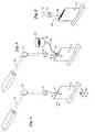
- Fig. 1shows a prior art molten pool.
- Fig. 2shows a molten pool of the present invention.
- Fig. 3shows a molten pool of the present invention including a build up of material.
- Fig. 4shows an energy source used to create a molten pool.
- Fig. 5shows material being deposited into the molten pool.
- Fig. 6shows an energy source with a large beam diameter at the substrate surface.
- Fig. 7Ashows an x-ray diffraction of point 1 denoting the crystallographic orientation of a build up of layers on a nickel base single crystal substrate.
- Fig. 7Bshows an x-ray diffraction of point 2 denoting the crystallographic orientation of a build up of layers on a nickel base single crystal substrate.
- Fig. 7Cshows an x-ray diffraction of point 3 denoting the crystallographic orientation of a build up of layers on a nickel base single crystal substrate.
- Fig. 8shows a top view of a deposited structure, taken at 25 times normal magnification:
- Fig. 9shows the crystallographic orientation at the center of the deposited structure of Fig. 8.
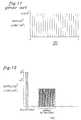
- Fig. 10shows the relationship between power density and time for an embodiment of the present invention as compared to a prior art process.
- Fig. 11shows a graphical representation of a prior art deposition process.
- Fig. 12shows a graphical representation of an embodiment of the present invention.
- the present inventionconcerns the melting of a filler material into a substrate or seed under conditions chosen to eliminate cracking.
- the seed or substrate 6(shown schematically in Fig. 1-Fig. 6) may be any metallic material.
- the substrate 6may be a nickel base, cobalt base, or other superalloy material.
- the substrate 6 or seedis a single crystal metallic article, preferably the ⁇ 100> crystal orientation is determined by x-ray diffraction. Crystals grown in this direction develop a desirable unidirectional structure. The substrate 6 or seed is positioned such that a [100] direction is vertically orientated. Although determination of the ⁇ 100> crystal orientation is desirable due to ease of crystal growth in this orientation, it is not essential for the practice of the present invention.
- the substrate 6may be preheated to help reduce stresses which can cause solid state cracking. Preheating may be accomplished by various methods known in the art including a laser beam, an induction heater, a quartz lamp or a standard clam-shell type furnace.
- Fig. 1is a schematic depiction of a prior art laser deposition process showing a molten pool 8 whose depth is significantly greater than its width. Heat flow is in the direction of arrow 1 and the solidification front moves in the direction of arrow 5. The solidification front moves generally toward the center line 3 of pool 8. Stresses result when the solidification fronts from opposites sides of pool 8 meet at center line 3. This stress is a cause of cracking in many prior art processes.
- Fig. 2shows a schematic illustration of the process of the present invention in which the diameter of the pool 8 is substantially greater than the depth of pool 8.
- Pool 8solidifies through heat extraction in direction 9 which causes the liquid solid interface to move toward direction 11 which is also toward the surface of substrate 6.
- This substantially planar front solidification processreduces cracking tendency significantly since the solidification front eventually coincides substantially with the free substrate surface 6. Therefore, there are no residual stresses in the material. Only at the pool edges, denoted as 15, may the solidification front not move directly toward the free surface of substrate 6.
- the present inventionprovides a method for the surface melting of crack prone metal articles without resulting cracking.
- the present inventionalso contemplates that the shallow pool 8 shown in Fig. 2 will be augmented through the addition of extra material, typically in the form of powder, but also possibly in the form of wire or foil, to cause a build up 17 as shown in Fig. 3.
- a laser beamor other suitable energy source, having a power density between 10 J/sec-cm 2 (10 watts/cm 2 ) and 10 4 J/sec-cm 2 (10 4 watts/cm 2 ), and preferably between 80 J/sec-cm 2 (80 watts/cm 2 ) and 800 J/sec-cm 2 (800 watts/cm 2 ) for a time period ranging from 0.10 seconds and 1000 seconds and preferably from 0.5 seconds to 100 seconds.
- a first energy sourcein this case a laser
- a laseris focused at a spot 4 on the substrate 6 or seed.
- a lasersuch as a YAG pulsed laser
- the power density of the lasermay be between 5 x 10 3 J/sec-cm 2 (5 x 10 3 watts/cm 2 ) and 5 x 10 6 J/sec-cm 2 (5 x 10 6 watts/cm 2 ), depending upon the heat input requirements of the substrate 6.
- the power densityis about 10 5 J/sec-cm 2 (10 5 watt/cm 2 ) for a nickel base single crystal substrate.
- the diameter of the beam spot on the substrate 6 produced by the laseris between 0.0254 mm (0.001 inches) and 2.54mm (0.100 inches)
- beam 10forms molten pool 8 on substrate 6.
- Filler materialis then deposited into pool 8.
- Materialmay be applied before or during beam 10 application.
- the materialis powder 18 with substantially the same composition as the substrate 6.
- the powderUpon depositing powder 18 in the pool 8, the powder melts and forms a deposit which rapidly solidifies upon removal of beam 10.
- the beam 10may be traversed across the substrate 6 thereby removing the heat input.
- a simultaneous application of powder 18 and beam 10 onto the substrate 6may be employed for simultaneous melting of powder 18 and substrate 6.
- a plurality of depositsmay be formed in the aforementioned manner. However these deposits will generally be cracked because of stresses associated with rapid solidification.
- the second energy sourcemay be the same energy source as the first energy source, adjusted at a lower power density.
- the power densitymay be between 10 J/sec-cm 2 (10 watts/cm 2 ) and 10 4 J/sec-cm 2 (10 4 watts/cm 2 ), depending upon the heat input requirements of the substrate 6.
- the power densityis about 600 J/sec-cm 2 (600watts/cm 2 ) for a nickel base single crystal substrate.
- the operating parameters with respect to power densitydo not overlap.
- Exposure time for the second energy sourcemay be between 0.1 seconds to 1000 seconds, and most preferably between 0.5 seconds to 100 seconds. Exposure time for the second energy source is preferably at least about 10 times greater than the exposure time for the first energy source in the production of each pool 8. Most preferably, exposure time is at least about 10 5 times greater.
- the spot diameter of the second energy source at the substrate surfaceis greater than the first energy source, as shown at 28 on Fig. 6. Most preferably, the spot diameter is at least about 5 times the spot diameter of the first energy source.
- the materialUpon removal of the second energy source, the material resolidifies, but at a slower rate than that of the first energy source. This slow solidification reduces the associated shrinkage stresses thereby essentially eliminating the propensity for crack formation. Solidification occurs unidirectionally, from the substrate 6 to the surface, thereby encouraging the continuation of the underlying crystal morphology and discouraging the formation of new grains.
- a solidified area 26 of depositsmay be formed. If the solidified area 26 is larger than the spot diameter of the second energy source, the area 26 may be melted by continuously moving an energy source across the deposited structure at a rate which allows the exposed material to melt such that unconstrained and unidirectional solidification is promoted. No over melting occurs which would result in loss of desired cross-section geometry.
- process steps for the creation of each layermay be performed concurrently, such as with the use of multiple energy sources.
- the surfacemay be finished.
- X-ray diffraction of the finished articlemay be performed to confirm continuation of the crystallographic orientation throughout the layers.
- Fig. 5schematically shows an apparatus suitable for the present invention.
- a powder feed device 20delivers powder 18 to pool 8.
- Powder feed device 20delivers powder 18 through powder feed line 22 to powder feed nozzle 24.
- the powder feed nozzle 24may be of a coaxial design to deliver power 18 coaxially around beam 10. Suitable powder flow rates may be between about 0.5 g/min and about 50 g/min, depending upon filler material, beam spot size and power density. Alternatively, the powder 18 may be preplaced on the substrate 6.
- Relative motion between the beam 10 and the componentmay be achieved by manipulation of optical elements or the substrate 6 by mechanical or electrical means.
- optical elementsFor example, opto-electric elements may be used.
- the material feedmay be directed by non-mechanical means using magnetic or electro-static effects.
- a three dimension computer model of the article to be fabricatedis created, for example, by a CAD system.
- incremental layersdefine individual cross sections of a component to be fabricated.
- the computer generated modelis used by the computer to guide a multi-axis part positioning system, such as a five-axis system, and/or a laser beam.
- the part positioning systemis greater than a three-axis system.
- horizontal part featurescan be constructed by rotating the component to build all features along a vertical axis to counteract the effects of gravity.
- the componentis fabricated one incremental layer at a time as defined by the computer model.
- a single crystal work piece (substrate) with a [100] crystal orientation and a nominal composition, by weight percent, of 5% Cr, 10% Co, 1.9% Mo, 5.9% W, 3% Re, 8.7% Ta, 5.65% Al, 0.1% Hf, balance Niwas cleaned with alcohol.
- the work piecewas then placed on a platform of a laser deposition apparatus.
- An Allen-Bradley 7320 NC controllerwas used to control the laser. As shown in Fig. 5, the laser emitted beam 10 which fell on mirror 12 that deflected the beam 10 toward the work piece. The beam 10 emitted from the laser passed through a lens system 14 arranged between the mirror 12 and the work piece. As the beam 10 emerged from lens system 14, it came to a focal point 16 at about the surface of the work piece.
- a spot diameter size of about 0.381 mm (0.015 inches)was produced at the work piece surface.
- a molten pool 8was then created.
- the molten pool 8was about 0.508 mm (0.02 inches) in diameter with a 0.203 mm (0.008 inch) depth.
- Each laser pulsecreated a pool 8 as the beam of the laser moved across the surface of the work piece.
- Disc rotationvaried between about 1 rpm and about 1.5 rpm causing a powder flow rate of about 15 g/min.
- the powder sizewas about 400 mesh (0.037 mm) and had the same composition as the work piece.
- the powder feedmoved in tandem with the laser such that powder landed in the molten pool(s) 8 created by the moving laser, thereby forming a deposited structure which then rapidly solidified.
- a deposited structure of eight rows of depositswas created. A space of about 0.381 mm (0.015 inches) existed between the center to center distance between the rows. A coated area of about 6.35 mm (0.25 inches) by 6.35 mm (0.25 inches) was created, however, it contained cracks.
- the processwas stopped.
- the pulse settingwas changed to 4 milliseconds; the pulse rate remained at 90 sec -1 (90 hertz), the laser average power was increased to 200 J/sec (200 watts) and the estimated spot diameter was increased to 6.35 mm (0.25 inches) at the work piece surface by changing the optical system. These changes lowered the power density to about 640 J/sec-cm 2 (640 watts/cm 2 ).
- the laserwas directed at the solidified area for about 60 seconds. The portion of the solidified area exposed to the laser melted and then slowly solidified in an unconstrained manner upon removal of the laser, thereby eliminating cracking and continuing the underlying single crystal orientation of the work piece.
- the sequence of 8 row formation followed by melting with a 6.35 mm diameter (0.25 inch) spot size laserwas sequentially repeated 30 times, resulting in the continuation of the single crystal orientation of the work piece throughout the created layers.
- X-ray diffractionswere taken at various points on the build up to determine crystallographic orientation.
- Fig. 7A, Fig. 7B and Fig. 7Care x-ray diffractions which denote the crystallographic orientation of point 1 (taken near end of build up opposite substrate), point 2 (taken approximately at center of build up) and point 3 (taken in substrate region), respectively.
- Fig. 8is a top view of the deposited structure at 25 times normal magnification showing the directional growth obtained by the deposition. As the deposited structure was formed, a YAG laser beam moved from one end of the deposited structure to the other.
- the parameters of the trialwere as follows. In the initial deposition phase, average laser power was about 100 J/sec (100 watts), pulse rate was 90 sec -1 (90 hertz) and pulse time was about 2 milliseconds. The power density was about 10 5 J/sec-cm 2 (10 5 watts/cm 2 ). Beam spot diameter at the substrate surface was about 0.381 mm (0.015 inches).
- the pulse rateremained at 90 sec -1 (90 hertz); pulse time was about 4 milliseconds, average laser power was about 200 J/sec (200 watts) J/sec) and the approximate spot diameter was increased to 6.35 mm (0.25 inches) at the work piece surface by changing the optical system. These changes lowered the power density to about 600 J/sec-cm 2 (600 watts/cm 2 ).
- Fig. 9shows alignment of the single crystal orientation in the [100] direction.
- An advantage of the present inventionis the ability to reduce material stresses transverse to the growth direction below an amount which causes cracking. This is accomplished by the novel second application of a heat source at a lower power density that melts the deposited layers which then directionally resolidify in an unconstrained manner at a lower rate.
- An unconstrained meltis not susceptible to hot tearing and subsequent stress cracking. Hot tearing is cracking that takes place in the partially molten state and is perceived as a major barrier in the production of crack free structures. Stress induced from the process after solidification is also reduced.
- the present inventionhas demonstrated the feasibility of a novel containerless method of producing a single crystal gas turbine engine component. This is a significant technical advancement.
- the present inventionalso has application in other related fields such as the creation of knife-edged seals which require a crack free deposit, as well as in the joining of metallic articles.
- the present inventionis also useful in the field of rapid prototyping development.
- Fig. 10shows the relationship between power density and time for the deposition process disclosed in the Brown patent as compared to the process of the present invention.
- the thin diagonal band on Fig. 10represents the useful operating conditions for the invention disclosed in the Brown patent.
- the useful operating conditions for the present inventionare distinct, as indicated on Fig. 10 where the approximate parameters for the one step embodiment as well as the approximate parameters for the embodiment including a subsequent remelt step are below the useful operating conditions described for the Brown process.
- a bar graph comparisonis presented in Fig. 11 and Fig. 12.
- Example 2 of the Brown patentmultiple thin layer of feedstock are sequentially deposited on top of one another upon completion of each revolution.
- a continuous energy sourceis employed.
- each vertical linerepresents a continuous revolution of deposited material.
- a depositis created by directing an energy source to create a molten pool and depositing material into the molten pool.
- Several depositsmay be formed in the aforementioned manner. Each deposit may take about 1-2 milliseconds to form.
- solidificationoccurs.
- the first set of vertical bars on Fig. 12denote this deposition.
- the deposit(s)is then exposed to lower power density (about 600 J/sec-cm 2 ) for a longer time (approximately 60 seconds). This extended exposure is shown on Fig. 12 also.
- solidificationoccurs at a much slower rate than previously.
- cooling rate(°C/s) is determined by the product of thermal gradient and growth rate. Although exact values are difficult to measure, reducing the cooling rate results in desirable from a crack reduction standpoint.
- the present inventionachieves this important result of reduction in cooling rate and thermal gradient, which in turn reduces the solidification rate. This reduces the stresses induced during solidification. By reducing the shrinkage stresses of solidification in this manner, the propensity for crack formation is essentially eliminated.
- Another benefit of the present inventionis the ability to achieve unidirectional solidification. By reducing the thermal gradient, the growth direction is controlled by the crystallographic orientation of the substrate.
- microstructures created according to the inventionare about one order of magnitude finer than those found in conventional castings.
- Nickel base superalloys, in cast form,generally have a dendrite microstructure.
- Dendritesare microscopic tree-like features which form during solidification and have a slightly different composition than the composition of the structure between the dendrites.
- Dendrite spacinghas some effect upon mechanical properties and upon the heat treatment required to achieve certain properties. For a given composition, dendrite spacing is a function of solidification rate and dendrite spacing is used to estimate cooling rates.
Landscapes
- Engineering & Computer Science (AREA)
- Chemical & Material Sciences (AREA)
- Mechanical Engineering (AREA)
- Optics & Photonics (AREA)
- Physics & Mathematics (AREA)
- Metallurgy (AREA)
- Organic Chemistry (AREA)
- Materials Engineering (AREA)
- Crystallography & Structural Chemistry (AREA)
- Plasma & Fusion (AREA)
- General Engineering & Computer Science (AREA)
- Inorganic Chemistry (AREA)
- Chemical Kinetics & Catalysis (AREA)
- Architecture (AREA)
- Crystals, And After-Treatments Of Crystals (AREA)
Description
- The present invention concerns a containerless methodfor producing a single crystal metal article according tothe precharacterizing portion of
claim 1 and acontainerless method of making a crack free metallicarticle according to the precharacterizing portion ofclaim 2. - The present invention relates generally to a containerless method ofproducing crack free metallic articles and particularly to a containerless methodof producing single crystal gas turbine engine components.
- Modern gas turbine engines operate at high rotational speeds and hightemperatures for increased performance and efficiency. Thus, the materials fromwhich gas turbine engine components are made of must be able to withstand thissevere operating environment.
- Most high temperature gas turbine engine components are made of nickelbase superalloys which are alloys specifically developed for high temperatureand high mechanical stress applications. Superalloys are often cast into thecomponent shape. For example, directional solidification is known in the art.This casting technique aligns grain boundaries parallel to the stress axis. Thisalignment enhances elevated temperature strength. Directional solidificationaligns the grains to minimize failure initiation sites because high temperaturefailure usually occurs at the boundaries between metal crystals.
- An extension of the above technique is single crystal casting. Casting ofalloys in single crystal form eliminates internal crystal boundaries in the finishedcomponent. Single crystal turbine blades and vanes possess superior characteristics such as strength, ductility, and crack resistance at high operationtemperatures. Thus, single crystal engine components are extensively used inthe turbine section of gas turbine engines. Although single crystal enginecomponents are desirable, they are extremely costly to manufacture and defectsoften occur during initial manufacturing.
- The successful use of conventional containerless laser depositionmethods is particularly difficult for producing single crystal components ofcomplex geometry because of inadvertent grain boundary introduction. Mostprior art fabrication processes have, to our knowledge, employed finely focusedlaser beams of high power density to interact with the metal substrate. Theresult has been cracking due to at least two phenomena. The first phenomenarelates to a high rate of solidification. The high rate of solidification results fromthe high temperature difference between the laser beam created molten pool andthe substrate. This temperature difference is a consequence of the rapid heatingrate which does not permit the unmelted substrate to achieve any significantlyelevated temperature. This means that when the laser beam moves on or is shutoff, the melted surface portion will rapidly solidify because the substrate acts asan extremely effective heat sink.
- More specifically, the high power densities and short exposure times leadto high thermal gradients and high cooling rates which result in rapidsolidification rates. This type of localized melting and solidification can inducethermal stresses during solidification which can lead to cracking.
- The second phenomena which leads to cracking and which results fromprior art teachings is that the pool is deep and has a high aspect ratio (depth towidth). In the solidification of such a relatively narrow deep molten pool,several adverse effects occur. For example the heat flow will be sideways fromthe pool as well as down into the substrate because of the relatively high ratio ofdepth to width. As the solidification reaches a conclusion, there will be a highstate of stress resulting from the constraint of the pool walls. The net effect of ahigh ratio is the introduction of high angle grain boundaries and a heavily constrained solidification condition. Introduction of high angle grain boundariesreduces the integrity of the material and increases the susceptibility to cracking.The high constraints of this type of solidification leads to high stresses duringand after solidification which can also lead to cracking. Thus, for the previouslyenumerated reasons, prior art laser metal treatment techniques have been proneto cracking and have generally been difficult to use.
- There have been attempts to alleviate some of these problems. Theseattempts include preheating the substrate to reduce cracking as well as the use ofdifferent filler materials, such as filler materials having more ductility and less ofa propensity for solidification cracking. Unfortunately, these attempts to solvethe problem have been relatively unsuccessful.
- The US-A-4 878 953 describes a process ofrefurbishing a superalloy casting comprising the steps of
- generating a plasma arc between an electrode and asection of the casting to be refurbished under an electriccurrent to melt a surface of said section into a shallowpool of molten metal;
- delivering welding powder of the same composition asthe superalloy casting into said arc at a point slightlyabove said molten pool for heating and delivery to saidmolten pool; and
- subsequently solidifying the delivered powder andmolten pool into an overlay, bonded to said casting andbeing of the same composition as the casting.
- Accordingly, there exists a need for a containerlessmethod of producing a crack free metallic article,particularly a single crystal gas turbine engine component.
- The containerless method for producing a singlecrystal metal article of the present invention is definedin the characterizing portion of
claim 1 and thecontainerless method of making a crack free metallicarticle of the present invention is defined in thecharacterizing portion ofclaim 2. - According to the present invention, a containerless method of producinga crack free metallic article is disclosed. More specifically, a containerlessmethod of producing a crack free single crystal gas turbine engine component isdisclosed.
- An aspect of the invention includes melting a filler material into asubstrate or seed under conditions chosen to eliminate cracking. In a preferredembodiment of the invention, a laser beam, or other suitable energy source, isoperated at a relatively low power density (between 10 J/sec-cm2 (10watts/cm2) and 104 J/sec-cm2 (104 watts/cm2) and at a relatively largediameter between 0.254 cm (0.1 inches) and about 10 cm (4 inches)), for anextended length of time (between 0.1 seconds and 1000 seconds), toproduce a molten pool with an aspect ratio which is relatively low, i.e. a shallowpool.
- Material is added to the pool, melts into the pool and solidifies to form adeposit. Alternatively, the material can be applied to the surface before or duringmelting. Preferably, the material added is powder having substantially the samecomposition as the substrate. However, depending on the specific application, amaterial with a different composition than that of the substrate may be desired.For example a corrosion resistant filler material would be desirable whencorrosion is a problem and strength is not as important. Depending upon thenature and cause of the defect, the material can be appropriately tailored toreduce the probability that the defect will recur.
- Laser beam operation at a relatively low power density and largediameter causes solidification to occur generally from the substrate outwardtoward the surface in a planar fashion as contrasted with previous techniques inwhich the solidification front was not controlled.
- The present invention solves the problem of cracking during laser metalprocessing by significantly changing the laser melting parameters. Whereas inthe prior art, processes have been performed at high power density over shorttime periods, according to the present invention, the power density is reducedand the interaction time is increased. This allows for a significant increase in thetemperature of the substrate immediately adjacent the molten pool at the timethat solidification occurs. By maintaining the substrate adjacent to the moltenpool at a relatively high temperature, the thermal gradient and rate ofsolidification are diminished. This reduced the likelihood of cracking. Thus, thepresent invention is capable of reducing the thermal gradient, cooling rate,solidification rate, and aspect ratio (depth to width) of the molten pool toproduce a single crystal metallic article.
- Yet another aspect of the invention includes a first step of melting fillermaterial into the substrate or seed, allowing solidification to occur, and remeltingthe filler material under conditions chosen to eliminate cracking. Specifically,an energy source melts a portion of the substrate and forms a pool. The powerdensity of the energy source may be 5 x 10³ J/sec-cm2 (5 x 10³ watt/cm2) and 5 x 10⁶ J/sec-cm2 (5 x 10⁶ watt/cm2), depending upon theheat input requirements of the substrate. Material is then added to the pool,melts into the pool and solidifies to form a deposit. Alternatively, the materialcan be applied to the surface before or during melting. The deposit rapidlysolidifies upon removal of the energy source as a result of heat conduction intothe substrate. The deposit, however, will very likely contain cracks because ofstresses during solidification.
- The deposit (and the surrounding region) is then remelted using anenergy source at a lower power density and for a longer exposure time using theparameters set forth previously for the broad one step embodiment. The energysource heats the substrate, thereby reducing the thermal gradient, thesolidification rate, as well as stresses during and after solidification. A crack freedeposit with no crystal boundaries results.
- The process is repeated, as required, to produce a crack free article ofdesired geometry. This is possible by applying the process in a closed-loop,controlled, multi-axis material deposition system. Each deposit melts intomaterial beneath each deposit and continues the crystallographic orientation ofthe substrate or seed upon solidification.
- In yet another embodiment of the present invention, several deposits areformed prior to remelting at a lower power density and for a longer time thaneach pool previously took to form. Remelting is performed with an energysource covering a larger article surface area than was previously covered.
- The present invention is capable of producing a crack free, near-net shapesingle crystal article. As a result, this invention is ideal for producing a singlecrystal gas turbine engine component without the use of a container, such as acasting mold. It is now possible to effectively produce a single crystal gasturbine engine component without the use of traditional casting technology.This is highly desirable because mold-metal interactions are eliminated, therebyimproving the efficiency of the production process.
- The present invention also allows deposition of an identical compositionto the underlying substrate or seed. Prior art processes have generallycompromised the substrate composition, such as with the addition of meltdepressants. No compositional compromises are necessary with the presentinvention. However, intentional compositional changes may be made to improvethe performance of the component and to enable the component to betterwithstand the service environment. For example, if oxidation resistance isdesired on a particular portion of the component, the deposited material in thatarea might be enriched with one or more elements such as Al, Cr, Y, La and Ce.If resistance to hot corrosion is desired, the region might be enriched with Cr.Fabricated regions which are stronger than the underlying seed or substrate canbe achieved by increasing the amounts of materials selected from the groupconsisting of Al, Ti, Ta, Nb(Cb), Mo and W. However, if increased ductility isdesired, than the above mentioned group of alloying elements should be reduced.
- The foregoing and other features and advantages of the present inventionwill become more apparent from the following description and accompanyingdrawings.
- Fig. 1 shows a prior art molten pool.
- Fig. 2 shows a molten pool of the present invention.
- Fig. 3 shows a molten pool of the present invention including a build upof material.
- Fig. 4 shows an energy source used to create a molten pool.
- Fig. 5 shows material being deposited into the molten pool.
- Fig. 6 shows an energy source with a large beam diameter at the substratesurface.
- Fig. 7A shows an x-ray diffraction of
point 1 denoting thecrystallographic orientation of a build up of layers on a nickel base single crystalsubstrate. - Fig. 7B shows an x-ray diffraction of
point 2 denoting thecrystallographic orientation of a build up of layers on a nickel base single crystalsubstrate. - Fig. 7C shows an x-ray diffraction of
point 3 denoting thecrystallographic orientation of a build up of layers on a nickel base single crystalsubstrate. - Fig. 8 shows a top view of a deposited structure, taken at 25 timesnormal magnification:
- Fig. 9 shows the crystallographic orientation at the center of thedeposited structure of Fig. 8.
- Fig. 10 shows the relationship between power density and time for anembodiment of the present invention as compared to a prior art process.
- Fig. 11 shows a graphical representation of a prior art deposition process.
- Fig. 12 shows a graphical representation of an embodiment of the presentinvention.
- The present invention concerns the melting of a filler material into asubstrate or seed under conditions chosen to eliminate cracking. The seed orsubstrate 6 (shown schematically in Fig. 1-Fig. 6) may be any metallic material.For example, the
substrate 6 may be a nickel base, cobalt base, or othersuperalloy material. - If the
substrate 6 or seed is a single crystal metallic article, preferably the<100> crystal orientation is determined by x-ray diffraction. Crystals grown inthis direction develop a desirable unidirectional structure. Thesubstrate 6 orseed is positioned such that a [100] direction is vertically orientated. Althoughdetermination of the <100> crystal orientation is desirable due to ease of crystalgrowth in this orientation, it is not essential for the practice of the presentinvention. - The
substrate 6 may be preheated to help reduce stresses which can causesolid state cracking. Preheating may be accomplished by various methodsknown in the art including a laser beam, an induction heater, a quartz lamp or astandard clam-shell type furnace. - Fig. 1 is a schematic depiction of a prior art laser deposition processshowing a
molten pool 8 whose depth is significantly greater than its width.Heat flow is in the direction ofarrow 1 and the solidification front moves in thedirection ofarrow 5. The solidification front moves generally toward thecenterline 3 ofpool 8. Stresses result when the solidification fronts from oppositessides ofpool 8 meet atcenter line 3. This stress is a cause of cracking in manyprior art processes. - Fig. 2 shows a schematic illustration of the process of the presentinvention in which the diameter of the
pool 8 is substantially greater than thedepth ofpool 8.Pool 8 solidifies through heat extraction in direction 9 whichcauses the liquid solid interface to move toward direction 11 which is alsotoward the surface ofsubstrate 6. This substantially planar front solidificationprocess reduces cracking tendency significantly since the solidification fronteventually coincides substantially with thefree substrate surface 6. Therefore,there are no residual stresses in the material. Only at the pool edges, denoted as15, may the solidification front not move directly toward the free surface ofsubstrate 6. - Thus, the present invention provides a method for the surface melting ofcrack prone metal articles without resulting cracking. The present invention alsocontemplates that the
shallow pool 8 shown in Fig. 2 will be augmented throughthe addition of extra material, typically in the form of powder, but also possiblyin the form of wire or foil, to cause a build up 17 as shown in Fig. 3. - We have found it to be possible to build up the surface of a
metalsubstrate 6 and thereby fabricate a metallic article. Importantly, we have foundthat when we practice the invention, we can continue the underlying crystalstructure without the formation of new grains or grain boundaries during this fabrication process. This is significant because it provides a method forfabricating single crystal articles. - In a preferred embodiment of the present invention, we employ a laserbeam, or other suitable energy source, having a power density between10 J/sec-cm2 (10 watts/cm2) and 104 J/sec-cm2 (104 watts/cm2), andpreferably between 80 J/sec-cm2 (80 watts/cm2) and 800 J/sec-cm2 (800watts/cm2) for a time period ranging from 0.10 seconds and 1000 secondsand preferably from 0.5 seconds to 100 seconds. This in combinationwith a laser beam, or other suitable energy source, having a diameter of between0.254cm (0.1 inches) and 10cm (4 inches) and preferably between0.51cm (0.2 inches) and 51cm (2 inches) will permit the formation ofthe shallow pool geometry illustrated in Fig. 2 and Fig. 3 rather than the deepnarrow pool shown in Fig. 1.
- In an alternative embodiment of the present invention, and as shown inFig. 4, a first energy source, in this case a laser, is focused at a
spot 4 on thesubstrate 6 or seed. A laser, such as a YAG pulsed laser, is preferred because ofits ability to produce small diameter spot sizes on the surface of thesubstrate 6or seed which increase the accuracy of the fabrication process. It is also possibleto use a continuous laser beam for the production of "lines" of deposits. Thepower density of the laser may be between 5 x 10³ J/sec-cm2 (5 x 10³watts/cm2) and 5 x 10⁶ J/sec-cm2 (5 x 10⁶ watts/cm2), depending upon theheat input requirements of thesubstrate 6. Preferably, the power density is about105 J/sec-cm2 (105 watt/cm2) for a nickel base single crystal substrate. - Preferably, the diameter of the beam spot on the
substrate 6 produced bythe laser is between 0.0254 mm (0.001 inches) and 2.54mm (0.100 inches) - Small diameter spot sizes increase the accuracy of the process, large spotsizes increase the rate of build up. Maximum spot size is dependent on availablepower.
- As shown in Fig. 5,
beam 10forms molten pool 8 onsubstrate 6. Fillermaterial is then deposited intopool 8. Material may be applied before or duringbeam 10 application. Preferably, the material ispowder 18 with substantially thesame composition as thesubstrate 6. - Upon depositing
powder 18 in thepool 8, the powder melts and forms adeposit which rapidly solidifies upon removal ofbeam 10. For example, thebeam 10 may be traversed across thesubstrate 6 thereby removing the heat input.Alternatively, a simultaneous application ofpowder 18 andbeam 10 onto thesubstrate 6 may be employed for simultaneous melting ofpowder 18 andsubstrate 6. A plurality of deposits may be formed in the aforementionedmanner. However these deposits will generally be cracked because of stressesassociated with rapid solidification. - The deposits are then remelted under conditions chosen to eliminatecracking, namely lower power density arid longer exposure time. Specifically,the second energy source may be the same energy source as the first energysource, adjusted at a lower power density. The power density may be between10 J/sec-cm2 (10 watts/cm2) and 104 J/sec-cm2 (104 watts/cm2),depending upon the heat input requirements of the
substrate 6. Preferably, thepower density is about 600 J/sec-cm2 (600watts/cm2) for a nickel base singlecrystal substrate. Most preferably, the operating parameters with respect topower density do not overlap. Exposure time for the second energy source maybe between 0.1 seconds to 1000 seconds, and most preferablybetween 0.5 seconds to 100 seconds. Exposure time for the secondenergy source is preferably at least about 10 times greater than the exposure timefor the first energy source in the production of eachpool 8. Most preferably,exposure time is at least about 105 times greater. - Preferably, the spot diameter of the second energy source at the substratesurface is greater than the first energy source, as shown at 28 on Fig. 6. Mostpreferably, the spot diameter is at least about 5 times the spot diameter of thefirst energy source.
- Upon removal of the second energy source, the material resolidifies, butat a slower rate than that of the first energy source. This slow solidification reduces the associated shrinkage stresses thereby essentially eliminating thepropensity for crack formation. Solidification occurs unidirectionally, from the
substrate 6 to the surface, thereby encouraging the continuation of the underlyingcrystal morphology and discouraging the formation of new grains. - The above steps can be repeated as needed for
substrate 6 buildup. Totaltime for article fabrication is dependent on article size. - As shown in Fig. 6, a solidified
area 26 of deposits may be formed. If thesolidifiedarea 26 is larger than the spot diameter of the second energy source,thearea 26 may be melted by continuously moving an energy source across thedeposited structure at a rate which allows the exposed material to melt such thatunconstrained and unidirectional solidification is promoted. No over meltingoccurs which would result in loss of desired cross-section geometry. - Alternatively, the process steps for the creation of each layer may beperformed concurrently, such as with the use of multiple energy sources.
- Once the desired build up of layers is produced, the surface may befinished. X-ray diffraction of the finished article may be performed to confirmcontinuation of the crystallographic orientation throughout the layers.
- Fig. 5 schematically shows an apparatus suitable for the presentinvention. As shown in Fig. 5, a
powder feed device 20 deliverspowder 18 topool 8.Powder feed device 20 deliverspowder 18 throughpowder feed line 22topowder feed nozzle 24. Thepowder feed nozzle 24 may be of a coaxialdesign to deliverpower 18 coaxially aroundbeam 10. Suitable powder flowrates may be between about 0.5 g/min and about 50 g/min, depending upon fillermaterial, beam spot size and power density. Alternatively, thepowder 18 maybe preplaced on thesubstrate 6. - Relative motion between the
beam 10 and the component may beachieved by manipulation of optical elements or thesubstrate 6 by mechanical orelectrical means. For example, opto-electric elements may be used. Thematerial feed may be directed by non-mechanical means using magnetic orelectro-static effects. - In a preferred technique, a three dimension computer model of the articleto be fabricated is created, for example, by a CAD system. In the model,incremental layers define individual cross sections of a component to befabricated. The computer generated model is used by the computer to guide amulti-axis part positioning system, such as a five-axis system, and/or a laserbeam. Preferably, the part positioning system is greater than a three-axis system.For example, with a five-axis positioning system, horizontal part features can beconstructed by rotating the component to build all features along a vertical axisto counteract the effects of gravity. The component is fabricated one incrementallayer at a time as defined by the computer model.
- The following examples are presented to further explain the presentinvention. It should be noted that for the power densities described in thespecification, between 30% and 35% of the values are absorbed withuse of a YAG laser and a nickel base substrate. However, if another laser orsubstrate is employed, the percent absorbed, as well as the power density, willvary accordingly. In addition, power values noted herein refer to average power.
- A single crystal work piece (substrate) with a [100] crystal orientationand a nominal composition, by weight percent, of 5% Cr, 10% Co, 1.9% Mo,5.9% W, 3% Re, 8.7% Ta, 5.65% Al, 0.1% Hf, balance Ni was cleaned withalcohol. The work piece was then placed on a platform of a laser depositionapparatus. A YAG pulsed laser with a pulse rate of 90 sec-1 (90 hertz), powertime of about 2 milliseconds, power density of about 105 J/sec-cm2 (105 watts/cm2) and power of 100 watts (100 J/sec), was focused at the center of the workpiece surface.
- An Allen-Bradley 7320 NC controller was used to control the laser. Asshown in Fig. 5, the laser emitted
beam 10 which fell onmirror 12 that deflectedthebeam 10 toward the work piece. Thebeam 10 emitted from the laser passedthrough alens system 14 arranged between themirror 12 and the work piece. As thebeam 10 emerged fromlens system 14, it came to afocal point 16 at aboutthe surface of the work piece. - A spot diameter size of about 0.381 mm (0.015 inches) was produced at thework piece surface. A
molten pool 8 was then created. Themolten pool 8 wasabout 0.508 mm (0.02 inches) in diameter with a 0.203 mm (0.008 inch) depth. Eachlaser pulse created apool 8 as the beam of the laser moved across the surface ofthe work piece. - A model 1260 Roto-Feed Control by Miller-Thermal, Inc., Appleton,Wisconsin was used to control powder flow rate. Disc rotation varied betweenabout 1 rpm and about 1.5 rpm causing a powder flow rate of about 15 g/min.The powder size was about 400 mesh (0.037 mm) and had the same composition as the workpiece. Argon gas at about 138 kPa (20 psi) continuously flowed into the
powderfeed device 20 to maintain powder under pressure and facilitate powder feedArgon was also used to provide a shielding environment to avoid work piececontamination. - The powder feed moved in tandem with the laser such that powderlanded in the molten pool(s) 8 created by the moving laser, thereby forming adeposited structure which then rapidly solidified.
- A deposited structure of eight rows of deposits was created. A space ofabout 0.381 mm (0.015 inches) existed between the center to center distancebetween the rows. A coated area of about 6.35 mm (0.25 inches) by 6.35 mm (0.25 inches)was created, however, it contained cracks.
- After formation of the eight rows, the process was stopped. The pulsesetting was changed to 4 milliseconds; the pulse rate remained at 90 sec-1 (90 hertz),
the laser average power was increased to 200 J/sec (200 watts) and theestimated spot diameter was increased to 6.35 mm (0.25 inches) at the work piecesurface by changing the optical system. These changes lowered the powerdensity to about 640 J/sec-cm2 (640 watts/cm2). The laser was directed at thesolidified area for about 60 seconds. The portion of the solidified area exposedto the laser melted and then slowly solidified in an unconstrained manner upon removal of the laser, thereby eliminating cracking and continuing the underlyingsingle crystal orientation of the work piece.
The sequence of 8 row formation followed by melting with a 6.35 mm diameter(0.25 inch) spot size laser was sequentially repeated 30 times, resultingin the continuation of the single crystal orientation of the work piece throughoutthe created layers. - X-ray diffractions were taken at various points on the build up todetermine crystallographic orientation. Fig. 7A, Fig. 7B and Fig. 7C are x-raydiffractions which denote the crystallographic orientation of point 1 (taken nearend of build up opposite substrate), point 2 (taken approximately at center ofbuild up) and point 3 (taken in substrate region), respectively.
- The difference in the crystallographic orientation of the points was lessthan about 5 degrees, thereby evincing the successful continuation of the singlecrystal orientation in the [100] direction throughout the build up. This alignmentis further evinced by the visible horizontal lines on Fig. 7A, Fig. 7B and Fig. 7Cwhich denote a similar crystallographic orientation.
- This trial utilized the same equipment, powder composition and substratecomposition as described in Example 1. In this trial, material 12.7 mm (0.5 inches)in length and 8 rows in width, was deposited onto a substrate. As inExample 1, a space of about 0.381 mm (0.015 inches) existed between the center tocenter distance between the rows. Fig. 8 is a top view of the deposited structureat 25 times normal magnification showing the directional growth obtained by thedeposition. As the deposited structure was formed, a YAG laser beam movedfrom one end of the deposited structure to the other.
- The parameters of the trial were as follows. In the initial depositionphase, average laser power was about 100 J/sec (100 watts), pulse rate was 90 sec-1(90 hertz) and pulse time was about 2 milliseconds. The power density was about 105 J/sec-cm2 (105 watts/cm2). Beam spot diameter at the substratesurface was about 0.381 mm (0.015 inches).
- In the remelting step, the pulse rate remained at 90 sec-1 (90 hertz); pulsetime was about 4 milliseconds, average laser power was about 200 J/sec (200 watts)J/sec) and the approximate spot diameter was increased to 6.35 mm (0.25 inches)at the work piece surface by changing the optical system. These changeslowered the power density to about 600 J/sec-cm2 (600 watts/cm2).
- This trial demonstrated the feasibility of depositing extended lengths ofsingle crystal material. Fig. 9 shows alignment of the single crystal orientationin the [100] direction.
- An advantage of the present invention is the ability to reduce materialstresses transverse to the growth direction below an amount which causescracking. This is accomplished by the novel second application of a heat sourceat a lower power density that melts the deposited layers which then directionallyresolidify in an unconstrained manner at a lower rate. An unconstrained melt isnot susceptible to hot tearing and subsequent stress cracking. Hot tearing iscracking that takes place in the partially molten state and is perceived as a majorbarrier in the production of crack free structures. Stress induced from theprocess after solidification is also reduced.
- The present invention has demonstrated the feasibility of a novelcontainerless method of producing a single crystal gas turbine enginecomponent. This is a significant technical advancement.
- The present invention also has application in other related fields such asthe creation of knife-edged seals which require a crack free deposit, as well as inthe joining of metallic articles. The present invention is also useful in the fieldof rapid prototyping development.
- The unique method of the present invention of melting a filler materialinto a metallic substrate under conditions chosen to eliminate cracking is readilydistinguishable from the deposition process disclosed in US-A-4,323,756to Brown et al. entitled,Method for Fabricating Articles by Sequential Layer Deposition.
- In the Brown deposition process, multiple thin layers offeed stock are deposited onto a substrate using a continuous energy beam. Thesethin layers are sequentially deposited on top of one another upon completion ofeach revolution of the deposition process.
- Fig. 10 shows the relationship between power density and time for thedeposition process disclosed in the Brown patent as compared to the process ofthe present invention. The thin diagonal band on Fig. 10 represents the usefuloperating conditions for the invention disclosed in the Brown patent.
- The useful operating conditions for the present invention, however, aredistinct, as indicated on Fig. 10 where the approximate parameters for the onestep embodiment as well as the approximate parameters for the embodimentincluding a subsequent remelt step are below the useful operating conditionsdescribed for the Brown process.
- To further distinguish the present invention from the process disclosed inBrown, a bar graph comparison is presented in Fig. 11 and Fig. 12. In Example2 of the Brown patent, multiple thin layer of feedstock are sequentially depositedon top of one another upon completion of each revolution. A continuous energysource is employed. Referring now to Fig. 11, each vertical line represents acontinuous revolution of deposited material. The mandrel rotated at 22 rpm anda fin of 2.54 cm (1 inch) in height was produced in 10 minutes 0.11 mm (0.00454 inch)height/revolution). As this deposition occurs, the power density remainedapproximately constant.
- However, in an embodiment of the present invention, and as described inExample 1, a deposit is created by directing an energy source to create a moltenpool and depositing material into the molten pool. Several deposits may beformed in the aforementioned manner. Each deposit may take about 1-2milliseconds to form. Upon removal of the energy source, solidification occurs.The first set of vertical bars on Fig. 12 denote this deposition.
- The deposit(s) is then exposed to lower power density (about 600 J/sec-cm2)for a longer time (approximately 60 seconds). This extended exposure isshown on Fig. 12 also. Upon removal of the energy source, solidification occursat a much slower rate than previously.
- It is known that cooling rate (°C/s) is determined by the product ofthermal gradient and growth rate. Although exact values are difficult tomeasure, reducing the cooling rate results in desirable from a crack reductionstandpoint. The present invention achieves this important result of reduction incooling rate and thermal gradient, which in turn reduces the solidification rate.This reduces the stresses induced during solidification. By reducing theshrinkage stresses of solidification in this manner, the propensity for crackformation is essentially eliminated.
- Another benefit of the present invention is the ability to achieveunidirectional solidification. By reducing the thermal gradient, the growthdirection is controlled by the crystallographic orientation of the substrate.
- In addition, the microstructures created according to the invention areabout one order of magnitude finer than those found in conventional castings.Nickel base superalloys, in cast form, generally have a dendrite microstructure.Dendrites are microscopic tree-like features which form during solidification andhave a slightly different composition than the composition of the structurebetween the dendrites.
- Dendrite spacing has some effect upon mechanical properties and uponthe heat treatment required to achieve certain properties. For a givencomposition, dendrite spacing is a function of solidification rate and dendritespacing is used to estimate cooling rates.
- In the present invention, even though steps are taken to reduce thecooling rates of the melted material from that which occurs in prior art laserprocesses, the cooling rates are still substantially greater than those which thesuperalloy material undergoes during normal casting. For conventionally castsuperalloys, primary dendrite spacing will range from 200 µm (microns) to 600 µm (microns). For material deposited by the present invention, dendritespacing may range from 20 µm (microns) to 180 µm (microns).
- Although the invention has been shown and described with respect todetailed embodiments thereof, it should be understood by those skilled in the artthat various changes in form and detail may be made without departing from thescope of the invention, as defined by the appended claims.
Claims (19)
- A containerless method for producing a singlecrystal metallic article comprising melting a fillermaterial (18) into a single crystal metallic substrate (6)having a single crystal structurecharacterized in using alow power density energy source between 10 J/sec-cm2 (10watts/cm2) and 104 J/sec-cm2 (104 watts/cm2) at a diametergreater than (0.254 cm) 0.1 inches for a length of timegreater than 0.1 seconds to produce a molten pool (8) witha low aspect ratio, wherein the single crystal structure ofthe substrate (6) is continued throughout the article toproduce a crack free article.
- A containerless method of making a crack freemetallic article comprising the steps of:(a) melting a portion of a substrate (6) with anenergy source, thereby creating a molten portion (8);(b) depositing filler material (18)in the moltenportion (8) and allowing the molten portion to solidify toform a solidified deposit; andcharacterized in(c) remelting the solidified deposit and a portion ofadjacent article under conditions of a lower power densityand a longer exposure time than that for the energy sourcein step (a) to produce a molten pool (8) with a low aspectratio, whereupon slow solidification occur without crackingto produce a crack free metallic article.
- The method of claim 2, further comprising the stepof:
(d) repeating steps (a)-(c) to produce a crack freearticle of desired geometry, each deposit melting into thefiller material (18) beneath each deposit. - The method of claim 2, wherein a plurality ofdeposits are formed prior to step (c).
- The method of claim 2, wherein steps (a) and (b)occur such that heat input and material supply aresimultaneously applied to the substrate prior to remelting.
- The method of claim 2, wherein step (c) isperformed with an energy source covering a larger articlesurface area than covered in step (a).
- The method of claim 2, wherein the energy source instep (d) has a spot diameter at the substrate surface atleast 5 times greater than the spot diameter of the energysource in step (a).
- The method of any preceding claim, wherein thesubstrate is preheated.
- The method of any preceding claim, furthercomprising the step of taking an x-ray diffraction of thesubstrate to determine the <100> crystallographicorientation and positioning the substrate so that a [100]crystallographic direction is vertically oriented.
- The method according to any of claims 2-7, whereinthe metallic article has a variance in crystallographicorientation less than about 5 degrees.
- The method according to any of claims 1-10,wherein the filler material (18) is substantially the samecomposition as the substrate.
- The method according to any of claims 1-10,wherein the filler material is enriched with one or more elements selected from the group consisting of Al, Ti, Ta,Nb (Cb), Mo, W, Cr, Y, La or Ce.
- The method according to any of claims 1-10,wherein the filler material (18) is enriched with Cr.
- The method according to any of claims 1-10,wherein the filler material (18) contains a decreasedamount of one or more elements selected from the groupconsisting of Al, Ti, Ta, Nb (Cb), Mo or W compared withthe composition of the article.
- The method according to any of claims 1-14,wherein said article is a nickel base or cobalt basesuperalloy article.
- The method according to any of claims 1-14,further comprising creating a three dimensional computermodel of the article to be produced, such that incrementallayers define individual cross sections to be produced,whereby the model is used by the computer to guide a multi-axispart positioning system, such as a five-axis system,and the energy source for production of horizontal featuresalong a vertical axis.
- The method according to any preceding claim,wherein said energy source is a laser.
- The method according to any preceding claim,wherein the article has a dendrite spacing between 20 µm(microns) and 180 µm (microns).
- The method according to claim 2, wherein saidlower power density of step (c) is between 10 J/sec-cm2 (10watts/cm2) and 104 J/sec-cm2 (104 watts/cm2).
Applications Claiming Priority (4)
| Application Number | Priority Date | Filing Date | Title |
|---|---|---|---|
| US43233595A | 1995-05-01 | 1995-05-01 | |
| US432335 | 1995-05-01 | ||
| US08/620,589US5900170A (en) | 1995-05-01 | 1996-03-22 | Containerless method of producing crack free metallic articles by energy beam deposition with reduced power density |
| US620589 | 1996-03-22 |
Publications (2)
| Publication Number | Publication Date |
|---|---|
| EP0740977A1 EP0740977A1 (en) | 1996-11-06 |
| EP0740977B1true EP0740977B1 (en) | 2001-11-21 |
Family
ID=27029454
Family Applications (1)
| Application Number | Title | Priority Date | Filing Date |
|---|---|---|---|
| EP96630026AExpired - LifetimeEP0740977B1 (en) | 1995-05-01 | 1996-04-25 | Containerless method of producing crack free metallic articles |
Country Status (5)
| Country | Link |
|---|---|
| US (2) | US5900170A (en) |
| EP (1) | EP0740977B1 (en) |
| JP (1) | JP3444723B2 (en) |
| DE (1) | DE69617087T2 (en) |
| TW (1) | TW332789B (en) |
Families Citing this family (71)
| Publication number | Priority date | Publication date | Assignee | Title |
|---|---|---|---|---|
| US6144008A (en)* | 1996-11-22 | 2000-11-07 | Rabinovich; Joshua E. | Rapid manufacturing system for metal, metal matrix composite materials and ceramics |
| EP0892090B1 (en)* | 1997-02-24 | 2008-04-23 | Sulzer Innotec Ag | Method for manufacturing single crystal structures |
| EP0861927A1 (en)* | 1997-02-24 | 1998-09-02 | Sulzer Innotec Ag | Method for manufacturing single crystal structures |
| SG85095A1 (en)* | 1998-06-24 | 2001-12-19 | Sulzer Innotec Ag | Method for producing monocrystalline structures |
| US6217286B1 (en)* | 1998-06-26 | 2001-04-17 | General Electric Company | Unidirectionally solidified cast article and method of making |
| US6054672A (en)* | 1998-09-15 | 2000-04-25 | Chromalloy Gas Turbine Corporation | Laser welding superalloy articles |
| US6269540B1 (en)* | 1998-10-05 | 2001-08-07 | National Research Council Of Canada | Process for manufacturing or repairing turbine engine or compressor components |
| DE69821945T2 (en)* | 1998-11-10 | 2005-07-14 | Alstom Technology Ltd | Gas turbine part |
| US6263918B1 (en) | 1999-04-29 | 2001-07-24 | The Regents Of The University Of California | Multiple feed powder splitter |
| US6284058B1 (en)* | 1999-09-15 | 2001-09-04 | U.T. Battelle, Llc | Method of aluminizing metal alloys by weld overlay using aluminum and aluminum alloy filler metal |
| US6243948B1 (en)* | 1999-11-18 | 2001-06-12 | General Electric Company | Modification and repair of film cooling holes in gas turbine engine components |
| US6333484B1 (en) | 2000-03-17 | 2001-12-25 | Chromalloy Gas Turbine Corporation | Welding superalloy articles |
| US6587742B2 (en)* | 2000-12-20 | 2003-07-01 | Mark Manuel | Method and apparatus for the creation of a tool |
| US6495793B2 (en) | 2001-04-12 | 2002-12-17 | General Electric Company | Laser repair method for nickel base superalloys with high gamma prime content |
| US6710280B2 (en)* | 2001-05-22 | 2004-03-23 | The P.O.M. Group | Focusing optics for adaptive deposition in rapid manufacturing |
| US7222834B2 (en)* | 2001-08-14 | 2007-05-29 | Floodcooling Technologies, Llc | Tool and a method for making a tool |
| EP1295969A1 (en) | 2001-09-22 | 2003-03-26 | ALSTOM (Switzerland) Ltd | Method of growing a MCrAIY-coating and an article coated with the MCrAIY-coating |
| EP1295970A1 (en) | 2001-09-22 | 2003-03-26 | ALSTOM (Switzerland) Ltd | MCrAlY type alloy coating |
| US20040038074A1 (en)* | 2001-11-01 | 2004-02-26 | Mark Manuel | Tool and a method for creating a tool |
| EP1340583A1 (en) | 2002-02-20 | 2003-09-03 | ALSTOM (Switzerland) Ltd | Method of controlled remelting of or laser metal forming on the surface of an article |
| EP1340567A1 (en) | 2002-02-27 | 2003-09-03 | ALSTOM (Switzerland) Ltd | Method of removing casting defects |
| DE50307242D1 (en)* | 2002-04-15 | 2007-06-21 | Siemens Ag | METHOD FOR PRODUCING SINGLE CRYSTALLINE STRUCTURES |
| US6837299B2 (en)* | 2002-04-26 | 2005-01-04 | Sky+Ltd. | Heating to control solidification of cast structure |
| US7295691B2 (en)* | 2002-05-15 | 2007-11-13 | Ge Medical Systems Global Technology Company, Llc | Computer aided diagnosis of an image set |
| DE10228743B4 (en)* | 2002-06-27 | 2005-05-04 | Fraunhofer-Gesellschaft zur Förderung der angewandten Forschung e.V. | Method for smoothing and polishing surfaces by machining with laser radiation |
| EP1396556A1 (en) | 2002-09-06 | 2004-03-10 | ALSTOM (Switzerland) Ltd | Method for controlling the microstructure of a laser metal formed hard layer |
| US7338717B2 (en)* | 2002-11-07 | 2008-03-04 | Floodcooling Technologies, Llc | Tool and a method for creating the tool |
| US7195223B2 (en)* | 2002-12-02 | 2007-03-27 | Mark Manuel | System and a method for cooling a tool |
| EP1426458B1 (en)* | 2002-12-06 | 2008-03-12 | ALSTOM Technology Ltd | Method of locally depositing a MCrAlY coating |
| US7009137B2 (en)* | 2003-03-27 | 2006-03-07 | Honeywell International, Inc. | Laser powder fusion repair of Z-notches with nickel based superalloy powder |
| US7250081B2 (en) | 2003-12-04 | 2007-07-31 | Honeywell International, Inc. | Methods for repair of single crystal superalloys by laser welding and products thereof |
| US20050196232A1 (en)* | 2004-03-05 | 2005-09-08 | Mark Manuel | Method and an apparatus for the creation of a tangible item, such as a tool and/or a part, and a tangible item |
| US20050274701A1 (en)* | 2004-06-10 | 2005-12-15 | United Technologies Corporation | Homogeneous welding via pre-heating for high strength superalloy joining and material deposition |
| US6872912B1 (en) | 2004-07-12 | 2005-03-29 | Chromalloy Gas Turbine Corporation | Welding single crystal articles |
| US7563091B2 (en)* | 2005-01-18 | 2009-07-21 | Floodcooling Technologies, L.L.C. | Tool having an ejection assembly, a method for making such a tool, and a method for ejecting a formed object from a tool |
| US7376484B2 (en)* | 2005-01-18 | 2008-05-20 | Floodcooling Technologies, Llc | Method for building a tool |
| US20070102837A1 (en)* | 2005-09-23 | 2007-05-10 | Mark Manuel | Tool having desired thermal management properties and a method for producing a tool having desired thermal management properties |
| US20060156787A1 (en)* | 2005-01-18 | 2006-07-20 | Mark Manuel | Laminated tool and a method for forming a tool |
| US7278197B2 (en)* | 2005-01-18 | 2007-10-09 | Floodcooling Technologies, Llc | Method for producing a tool |
| US7379787B2 (en)* | 2005-04-09 | 2008-05-27 | Floodcooling Technologies, Llc | Method for forming a tangible item and a tangible item formed by the method |
| US7094988B1 (en) | 2005-04-18 | 2006-08-22 | Honeywell International, Inc. | Laser welding heat treat process |
| US20070040298A1 (en)* | 2005-08-18 | 2007-02-22 | Mark Manuel | Assembly and a method for cooling and/or forming an item |
| US20070039153A1 (en)* | 2005-08-18 | 2007-02-22 | Mark Manuel | Method for forming a tool and a tool |
| US20070067977A1 (en)* | 2005-09-29 | 2007-03-29 | Mark Manuel | Tool and a method for producing a tool |
| FR2893268B1 (en)* | 2005-11-15 | 2008-02-08 | Snecma Sa | METHOD OF MAKING A REBORD LOCATED AT THE FREE END OF A DAWN, DAWN OBTAINED BY THIS PROCESS AND TURBOMACHINE EQUIPPED WITH SAID DARK |
| JP2009025119A (en)* | 2007-07-19 | 2009-02-05 | General Electric Co <Ge> | Profile measuring apparatus and operating method |
| DE102008018708A1 (en)* | 2008-04-14 | 2009-10-22 | Fraunhofer-Gesellschaft zur Förderung der angewandten Forschung e.V. | Method for welding in dependence on a preferred direction of the substrate |
| RU2466841C2 (en)* | 2008-05-29 | 2012-11-20 | Сименс Акциенгезелльшафт | Method and device for welding parts from heat-resistant alloys |
| JP5061062B2 (en)* | 2008-08-08 | 2012-10-31 | パナソニック株式会社 | Manufacturing method of three-dimensional shaped object |
| US8334475B2 (en)* | 2008-11-04 | 2012-12-18 | Rabinovich Joshua E | Process for energy beam solid-state metallurgical bonding of wires having two or more flat surfaces |
| US8726501B2 (en)* | 2009-08-31 | 2014-05-20 | General Electric Company | Method of welding single crystal turbine blade tips with an oxidation-resistant filler material |
| DE102009050676A1 (en)* | 2009-10-23 | 2011-05-05 | Schunk Gmbh & Co. Kg Spann- Und Greiftechnik | Method for the application welding of a material, comprises applying a welding pulse on the material, and treating the material with a conditioning pulse before the application of the welding pulse |
| EP2317079B1 (en)* | 2009-10-30 | 2020-05-20 | Ansaldo Energia Switzerland AG | Abradable coating system |
| EP2317076B1 (en)* | 2009-10-30 | 2018-02-14 | Ansaldo Energia IP UK Limited | A method for repairing a gas turbine component |
| EP2319641B1 (en)* | 2009-10-30 | 2017-07-19 | Ansaldo Energia IP UK Limited | Method to apply multiple materials with selective laser melting on a 3D article |
| EP2317075B1 (en)* | 2009-10-30 | 2013-01-02 | Alstom Technology Ltd | Method for repairing a gas turbine component |
| US8728388B2 (en)* | 2009-12-04 | 2014-05-20 | Honeywell International Inc. | Method of fabricating turbine components for engines |
| US8618434B2 (en)* | 2010-03-22 | 2013-12-31 | Siemens Energy, Inc. | Superalloy repair welding using multiple alloy powders |
| US9126287B2 (en) | 2012-03-12 | 2015-09-08 | Siemens Energy, Inc. | Advanced pass progression for build-up welding |
| EP2756915A1 (en)* | 2013-01-18 | 2014-07-23 | Siemens Aktiengesellschaft | Build-up welding with previous remelting |
| US10173264B2 (en) | 2013-03-15 | 2019-01-08 | United Technologies Corporation | Additive manufacturing baffles, covers, and dies |
| US9539764B2 (en) | 2013-03-15 | 2017-01-10 | United Technologies Corporation | Usage of a witness mark to distinguish support structure from part |
| US9695697B2 (en)* | 2013-09-25 | 2017-07-04 | General Electric Company | Erosion shield, method of fabricating a shield, and method of fabricating an article having a shield |
| US20170088918A1 (en)* | 2014-09-19 | 2017-03-30 | General Electric Company | Materials for direct metal laser melting |
| US20160082511A1 (en)* | 2014-09-19 | 2016-03-24 | General Electric Company | Materials for direct metal laser melting |
| US20160375522A1 (en)* | 2015-06-26 | 2016-12-29 | Siemens Energy, Inc. | Welding method for superalloys |
| US10722946B2 (en) | 2016-04-25 | 2020-07-28 | Thomas Strangman | Methods of fabricating turbine engine components |
| US20180141160A1 (en)* | 2016-11-21 | 2018-05-24 | General Electric Company | In-line laser scanner for controlled cooling rates of direct metal laser melting |
| US11135677B2 (en) | 2018-03-06 | 2021-10-05 | General Electric Company | Laser welding of component |
| US10486272B2 (en)* | 2018-03-06 | 2019-11-26 | General Electric Company | Turbine blade tip rail formation and repair using laser welding |
| WO2022133613A1 (en)* | 2020-12-23 | 2022-06-30 | Her Majesty The Queen In Right Of Canada As Represented By The Minister Of Natural Resources Canada | Repair welding method by laser deposition using a filler wire |
Family Cites Families (34)
| Publication number | Priority date | Publication date | Assignee | Title |
|---|---|---|---|---|
| NL7216832A (en)* | 1972-12-12 | 1974-06-14 | ||
| US4028787A (en)* | 1975-09-15 | 1977-06-14 | Cretella Salvatore | Refurbished turbine vanes and method of refurbishment thereof |
| CA1095387A (en)* | 1976-02-17 | 1981-02-10 | Conrad M. Banas | Skin melting |
| GB2052566B (en)* | 1979-03-30 | 1982-12-15 | Rolls Royce | Laser aplication of hard surface alloy |
| US4323756A (en)* | 1979-10-29 | 1982-04-06 | United Technologies Corporation | Method for fabricating articles by sequential layer deposition |
| US4359352A (en)* | 1979-11-19 | 1982-11-16 | Marko Materials, Inc. | Nickel base superalloys which contain boron and have been processed by a rapid solidification process |
| JPS5695464A (en)* | 1979-12-14 | 1981-08-01 | Secr Defence Brit | Directional coagulating method |
| US4382169A (en)* | 1981-03-24 | 1983-05-03 | Rabkin Daniil M | Weld deposition of metal other than aluminium onto aluminium-base alloy |
| IT1179061B (en)* | 1984-08-20 | 1987-09-16 | Fiat Auto Spa | PROCEDURE FOR CARRYING OUT A TREATMENT ON METAL PIECES WITH THE ADDITION OF A VALUE MATERIAL AND WITH THE USE OF A POWER LASER |
| US4743733A (en)* | 1984-10-01 | 1988-05-10 | General Electric Company | Method and apparatus for repairing metal in an article |
| US4944817A (en)* | 1986-10-17 | 1990-07-31 | Board Of Regents, The University Of Texas System | Multiple material systems for selective beam sintering |
| US4927992A (en)* | 1987-03-04 | 1990-05-22 | Westinghouse Electric Corp. | Energy beam casting of metal articles |
| US4804815A (en)* | 1987-06-01 | 1989-02-14 | Quantum Laser Corporation | Process for welding nickel-based superalloys |
| US4878953A (en)* | 1988-01-13 | 1989-11-07 | Metallurgical Industries, Inc. | Method of refurbishing cast gas turbine engine components and refurbished component |
| US5273204A (en)* | 1988-03-25 | 1993-12-28 | Howmet Corporation | Method for joining materials by metal spraying |
| US4940390A (en)* | 1988-05-05 | 1990-07-10 | Westinghouse Electric Corp. | Turbine system having more failure resistant rotors and repair welding of low alloy ferrous turbine components by controlled weld build-up |
| US5038014A (en)* | 1989-02-08 | 1991-08-06 | General Electric Company | Fabrication of components by layered deposition |
| US5135695A (en)* | 1989-12-04 | 1992-08-04 | Board Of Regents The University Of Texas System | Positioning, focusing and monitoring of gas phase selective beam deposition |
| ES2056430T3 (en)* | 1989-12-27 | 1994-10-01 | Sulzer Innotec Ag | DEVICE FOR WELDING AND / OR COATING WORKPIECES, NOZZLES FOR A DEVICE OF THIS TYPE AS WELL AS A HANDLER FOR THE NOZZLE OF A DEVICE OF THIS TYPE. |
| JP2890658B2 (en)* | 1990-04-23 | 1999-05-17 | いすゞ自動車株式会社 | Local strengthening method of aluminum casting parts |
| JPH04120259A (en)* | 1990-09-10 | 1992-04-21 | Agency Of Ind Science & Technol | Method and device for producing equipment member by laser beam spraying |
| US5106010A (en)* | 1990-09-28 | 1992-04-21 | Chromalloy Gas Turbine Corporation | Welding high-strength nickel base superalloys |
| US5113582A (en)* | 1990-11-13 | 1992-05-19 | General Electric Company | Method for making a gas turbine engine component |
| DE4039807C1 (en)* | 1990-12-13 | 1991-10-02 | Mtu Muenchen Gmbh | |
| US5160822A (en)* | 1991-05-14 | 1992-11-03 | General Electric Company | Method for depositing material on the tip of a gas turbine engine airfoil using linear translational welding |
| US5312584A (en)* | 1992-02-18 | 1994-05-17 | General Motors Corporation | Moldless/coreless single crystal castings of nickel-aluminide |
| DE59208497D1 (en)* | 1992-03-02 | 1997-06-19 | Sulzer Innotec Ag | Free-form welding of metal structures with lasers |
| US5291937A (en)* | 1992-07-30 | 1994-03-08 | General Electric Company | Method for providing an extension on an end of an article having internal passageways |
| US5304039A (en)* | 1992-07-30 | 1994-04-19 | General Electric Company | Method for providing an extension on an end of an article and extended article |
| US5554837A (en)* | 1993-09-03 | 1996-09-10 | Chromalloy Gas Turbine Corporation | Interactive laser welding at elevated temperatures of superalloy articles |
| US5393482A (en)* | 1993-10-20 | 1995-02-28 | United Technologies Corporation | Method for performing multiple beam laser sintering employing focussed and defocussed laser beams |
| US5783318A (en)* | 1994-06-22 | 1998-07-21 | United Technologies Corporation | Repaired nickel based superalloy |
| US5425912A (en)* | 1994-07-07 | 1995-06-20 | Inco Alloys International, Inc. | Low expansion superalloy with improved toughness |
| US5673745A (en)* | 1996-06-27 | 1997-10-07 | General Electric Company | Method for forming an article extension by melting of an alloy preform in a ceramic mold |
- 1996
- 1996-03-22USUS08/620,589patent/US5900170A/ennot_activeExpired - Lifetime
- 1996-04-25DEDE69617087Tpatent/DE69617087T2/ennot_activeExpired - Lifetime
- 1996-04-25EPEP96630026Apatent/EP0740977B1/ennot_activeExpired - Lifetime
- 1996-05-01JPJP13438596Apatent/JP3444723B2/ennot_activeExpired - Fee Related
- 1996-06-19TWTW085107492Apatent/TW332789B/ennot_activeIP Right Cessation
- 1997
- 1997-11-21USUS08/976,239patent/US6103402A/ennot_activeExpired - Lifetime
Also Published As
| Publication number | Publication date |
|---|---|
| US6103402A (en) | 2000-08-15 |
| DE69617087D1 (en) | 2002-01-03 |
| US5900170A (en) | 1999-05-04 |
| EP0740977A1 (en) | 1996-11-06 |
| JP3444723B2 (en) | 2003-09-08 |
| DE69617087T2 (en) | 2002-04-18 |
| JPH09118592A (en) | 1997-05-06 |
| TW332789B (en) | 1998-06-01 |
Similar Documents
| Publication | Publication Date | Title |
|---|---|---|
| EP0740977B1 (en) | Containerless method of producing crack free metallic articles | |
| EP0740976B1 (en) | Method of repairing single crystal metallic articles | |
| EP1478482B1 (en) | Method of removing casting defects | |
| CA2230323C (en) | Method for producing monocrystalline structures | |
| JP6494680B2 (en) | Material processing with optically transparent slag | |
| EP1424158B1 (en) | A method for fabricating, modifying or repairing of single crystal or directionally solidified articles | |
| JP6022679B2 (en) | Repair of directionally solidified alloys | |
| EP2543467A1 (en) | Method of welding a gamma-prime precipitate strengthened material | |
| EP1207212B1 (en) | Nickel alloy composition | |
| EP1798316B1 (en) | Repair method of crystalline structures by epitaxy | |
| WO2010011564A1 (en) | Reusable mandrel for solid free form fabrication process | |
| US6837299B2 (en) | Heating to control solidification of cast structure | |
| WO2025145078A1 (en) | Converting a polycrystalline shell to single crystal in superalloys produced via additive manufacturing |
Legal Events
| Date | Code | Title | Description |
|---|---|---|---|
| PUAI | Public reference made under article 153(3) epc to a published international application that has entered the european phase | Free format text:ORIGINAL CODE: 0009012 | |
| AK | Designated contracting states | Kind code of ref document:A1 Designated state(s):CH DE FR GB LI | |
| 17P | Request for examination filed | Effective date:19970426 | |
| 17Q | First examination report despatched | Effective date:19981229 | |
| GRAG | Despatch of communication of intention to grant | Free format text:ORIGINAL CODE: EPIDOS AGRA | |
| GRAG | Despatch of communication of intention to grant | Free format text:ORIGINAL CODE: EPIDOS AGRA | |
| GRAH | Despatch of communication of intention to grant a patent | Free format text:ORIGINAL CODE: EPIDOS IGRA | |
| GRAH | Despatch of communication of intention to grant a patent | Free format text:ORIGINAL CODE: EPIDOS IGRA | |
| GRAA | (expected) grant | Free format text:ORIGINAL CODE: 0009210 | |
| AK | Designated contracting states | Kind code of ref document:B1 Designated state(s):CH DE FR GB LI | |
| REG | Reference to a national code | Ref country code:CH Ref legal event code:EP | |
| REG | Reference to a national code | Ref country code:GB Ref legal event code:IF02 | |
| REF | Corresponds to: | Ref document number:69617087 Country of ref document:DE Date of ref document:20020103 | |
| ET | Fr: translation filed | ||
| PLBE | No opposition filed within time limit | Free format text:ORIGINAL CODE: 0009261 | |
| STAA | Information on the status of an ep patent application or granted ep patent | Free format text:STATUS: NO OPPOSITION FILED WITHIN TIME LIMIT | |
| 26N | No opposition filed | ||
| PGFP | Annual fee paid to national office [announced via postgrant information from national office to epo] | Ref country code:CH Payment date:20070427 Year of fee payment:12 | |
| REG | Reference to a national code | Ref country code:CH Ref legal event code:PL | |
| PG25 | Lapsed in a contracting state [announced via postgrant information from national office to epo] | Ref country code:LI Free format text:LAPSE BECAUSE OF NON-PAYMENT OF DUE FEES Effective date:20080430 Ref country code:CH Free format text:LAPSE BECAUSE OF NON-PAYMENT OF DUE FEES Effective date:20080430 | |
| PGFP | Annual fee paid to national office [announced via postgrant information from national office to epo] | Ref country code:FR Payment date:20100521 Year of fee payment:15 | |
| REG | Reference to a national code | Ref country code:FR Ref legal event code:ST Effective date:20111230 | |
| PG25 | Lapsed in a contracting state [announced via postgrant information from national office to epo] | Ref country code:FR Free format text:LAPSE BECAUSE OF NON-PAYMENT OF DUE FEES Effective date:20110502 | |
| PGFP | Annual fee paid to national office [announced via postgrant information from national office to epo] | Ref country code:GB Payment date:20150324 Year of fee payment:20 | |
| PGFP | Annual fee paid to national office [announced via postgrant information from national office to epo] | Ref country code:DE Payment date:20150319 Year of fee payment:20 | |
| REG | Reference to a national code | Ref country code:DE Ref legal event code:R071 Ref document number:69617087 Country of ref document:DE | |
| REG | Reference to a national code | Ref country code:GB Ref legal event code:PE20 Expiry date:20160424 | |
| PG25 | Lapsed in a contracting state [announced via postgrant information from national office to epo] | Ref country code:GB Free format text:LAPSE BECAUSE OF EXPIRATION OF PROTECTION Effective date:20160424 |