EP0738495B1 - Pressure measuring guide wire - Google Patents
Pressure measuring guide wireDownload PDFInfo
- Publication number
- EP0738495B1 EP0738495B1EP95105777AEP95105777AEP0738495B1EP 0738495 B1EP0738495 B1EP 0738495B1EP 95105777 AEP95105777 AEP 95105777AEP 95105777 AEP95105777 AEP 95105777AEP 0738495 B1EP0738495 B1EP 0738495B1
- Authority
- EP
- European Patent Office
- Prior art keywords
- length
- guide wire
- pressure measuring
- measuring guide
- wire according
- Prior art date
- Legal status (The legal status is an assumption and is not a legal conclusion. Google has not performed a legal analysis and makes no representation as to the accuracy of the status listed.)
- Expired - Lifetime
Links
Images
Classifications
- A—HUMAN NECESSITIES
- A61—MEDICAL OR VETERINARY SCIENCE; HYGIENE
- A61B—DIAGNOSIS; SURGERY; IDENTIFICATION
- A61B5/00—Measuring for diagnostic purposes; Identification of persons
- A61B5/68—Arrangements of detecting, measuring or recording means, e.g. sensors, in relation to patient
- A61B5/6846—Arrangements of detecting, measuring or recording means, e.g. sensors, in relation to patient specially adapted to be brought in contact with an internal body part, i.e. invasive
- A61B5/6847—Arrangements of detecting, measuring or recording means, e.g. sensors, in relation to patient specially adapted to be brought in contact with an internal body part, i.e. invasive mounted on an invasive device
- A61B5/6851—Guide wires
- A—HUMAN NECESSITIES
- A61—MEDICAL OR VETERINARY SCIENCE; HYGIENE
- A61B—DIAGNOSIS; SURGERY; IDENTIFICATION
- A61B5/00—Measuring for diagnostic purposes; Identification of persons
- A61B5/02—Detecting, measuring or recording for evaluating the cardiovascular system, e.g. pulse, heart rate, blood pressure or blood flow
- A61B5/021—Measuring pressure in heart or blood vessels
- A61B5/0215—Measuring pressure in heart or blood vessels by means inserted into the body
- A—HUMAN NECESSITIES
- A61—MEDICAL OR VETERINARY SCIENCE; HYGIENE
- A61M—DEVICES FOR INTRODUCING MEDIA INTO, OR ONTO, THE BODY; DEVICES FOR TRANSDUCING BODY MEDIA OR FOR TAKING MEDIA FROM THE BODY; DEVICES FOR PRODUCING OR ENDING SLEEP OR STUPOR
- A61M25/00—Catheters; Hollow probes
- A61M25/01—Introducing, guiding, advancing, emplacing or holding catheters
- A61M25/09—Guide wires
- A61M25/09016—Guide wires with mandrils
- A61M25/09025—Guide wires with mandrils with sliding mandrils
- A—HUMAN NECESSITIES
- A61—MEDICAL OR VETERINARY SCIENCE; HYGIENE
- A61M—DEVICES FOR INTRODUCING MEDIA INTO, OR ONTO, THE BODY; DEVICES FOR TRANSDUCING BODY MEDIA OR FOR TAKING MEDIA FROM THE BODY; DEVICES FOR PRODUCING OR ENDING SLEEP OR STUPOR
- A61M25/00—Catheters; Hollow probes
- A61M25/01—Introducing, guiding, advancing, emplacing or holding catheters
- A61M25/09—Guide wires
- A61M2025/09058—Basic structures of guide wires
- A61M2025/09083—Basic structures of guide wires having a coil around a core
- A61M2025/09091—Basic structures of guide wires having a coil around a core where a sheath surrounds the coil at the distal part
Definitions
- This inventionrelates to a pressure measuring guide wire comprising an elongated flexible shaft with a proximal area, a distal area, a lumen extending through the shaft, wall means surrounding said lumen, and aperture means for entry of a pressure medium into the lumen.
- the problem of pressure measuring guide wiresis to provide an uninterrupted lumen throughout the shaft which has to be highly flexible to conform with the tortuous pathways of the blood vessels; simultaneously, the shaft must have a reasonably high stiffness to assure pushability and torque transmission thereto; and furthermore, the shaft must have a very good kink resistance to avoid the risk of constrictions resulting in modification of the advance of pressure waves through the lumen.
- a safety wireextends from the joint of the two coils to the distal extremity of the coil spring where it is secured to a transducer carried by the distal end of the coil spring.
- Front and rear contactsare provided on the transducer and are connected to a two conductor wire which extends rearwardly and interiorly of the coil spring and further extends into the tube between the core wire and the interior of the tube to get out of the tube for connection to a male connector.
- an insulating sleevemay form a tight fit with the exterior surface of the core wire and it may also fit within the tube to insulate the core from the tube so that the core and the tube and core may serve as separate and independent electrical conductors.
- Document EP 0 397 173shows a pressure monitoring guidewire with a flexible distal portion.
- This guidewirecomprises an elongated flexible shaft with proximal and distal area, wall means surrounding a lumen and aperture means for entry of a pressure medium.
- the wall meanshave a first portion of length with a first resistance to kinking, a second portion of length with a second resistance to kinking smaller than said first resistance and coils means for supporting said second portion of length.
- a pressure measuring guide wirecomprising an elongated flexible shaft with a proximal area, a distal area, a lumen extending through the shaft, wall means surrounding said lumen, and aperture means for entry of a pressure medium into the lumen, wherein said wall means have a first portion of length having a first resistance to kinking, a second portion of length having a second resistance to kinking, said second resistance to kinking being smaller than said first resistance to kinking, and wherein coil means are supporting said second portion of length. Accordingly, it becomes possible to modulate the resistance to kinking as a function of the structural organization for the pressure medium entry into the lumen.
- the wall thicknessmay be selected at will, whereby the shaft can be made flexible and stiff enough to be pushed.
- the resistance to kinkingcan be practically constant and the risk of constrictions due to kinking is eliminated.
- a stiffening wireis no more needed, and there is a better frequency behaviour for the fluid medium.
- the first portion of lengthis in the distal area of the shaft, making it possible to select at will the configuration of the supporting coil means.
- the first portion of lengthmay have a first outer diameter and the second portion of length may have a second outer diameter smaller than the first outer diameter, whereby the coil means may surround the second portion of length.
- the coil means and diametersmay be easily chosen to have the coil means in flush alignment with the first outer diameter, for having an overall outer diameter constant and reduced friction upon travelling through the blood vessels.
- this second portion of lengthmay be preceded proximally by a third portion of length having a third outer diameter larger than said second outer diameter, with the coil means surrounding the second portion of length between said first and third outer diameters.
- the coil meansmay also be in flush alignment with the first outer diameter for the same reason of diameter constancy and friction reduction.
- some of the slotsmay be proximal of the first portion of length with some other slots being distal of the first portion of length, thereby avoiding too many holes on the same diameter in order to minimize the risk of kinking resistance reduction in that area.
- core meansmay extend through the coil means. Where such core means have a proximal portion for longitudinal abutment against a proximal end of the coil means and a distal portion for longitudinal abutment with a distal end of the coil means, a stress free assembly is achieved which stiffens the turns of the coil means and which leaves the shaft lumen free of any obstruction proximally of the coil means.
- the core meansmay also have their proximal portion integral with a wire which extends proximally along and out of the lumen of the shaft. In that case, the supporting coil may be placed under the slots only for insertion of the guide wire to assure the required resistance to kinking. During insertion, the wire extending the core also has some stiffening effect for the shaft and improves its pushability. When the guide wire is properly located, the wire and supporting coil are removed from the guide wire to have the shaft lumen fully free of obstruction for pressure measurements.
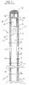
- Figure 1is a cross sectional view of the first embodiment.
- the guide wire shown in Figure 1comprises an elongated flexible shaft 1 having a distal area 2 and a proximal area 3.
- a lumen 4extends through the shaft 1, and the proximal area 3 of the shaft is intended to be connected to a pressure measuring and monitoring equipment (not shown) common in the art.
- the shaft 1is made of an elastic Nickel Titanium alloy such as for instance Nitinol (Trade Name) or Tinel Alloy (Trade Name). Other materials are also possible, for instance plastic materials.
- the lumen 4is surrounded by a wall 5 forming the shaft 1 and having a first portion of length 6 and a second portion of length 7.
- the first portion of length 6is located in the distal area 2 of the shaft 1 and it has a first thickness 8; the second portion of length 7 is located in the proximal area 3 of shaft 1 and it has a second thickness 9, smaller than the first thickness 8, thereby achieving a resistance to kinking which is smaller than that of the first portion of length 6.
- the difference in thicknessresults from the fact that the first portion of length 6 has an outer diameter 11 longer than the diameter 12 of the second portion of length 7.
- the first portion of length 6has a plurality of slots 10 formed therein for entry of the pressure medium; some of these slots 10 are proximal of the first portion of length 6 and some other of these slots are distal of the first portion of length 6.
- This high density metal coilalso provides a radiopaque reference for the first portion of length 6.
- This coil 13is in flush alignment with the outer diameter 11 of the first portion of length 6.
- the second portion of length 7is preceded proximally by a third portion of length 14 of wall 5 having an outer diameter 15 greater than the second diameter 12, in the example shown, equal to the first outer diameter 11.
- the coil 13is thus comprised between the first diameter 11 and the third diameter 15.
- the distal area 2 of shaft 1terminates in a flexible assembly 16 comprising a coil 17, preferably made of a high density metal such as Tungsten, which also provides a radiopaque reference for the first portion of length 6 which is thus easily locatable between the two radiopaque references provided for by coils 13 and 17.
- the coil 17abuts proximally on the distal end 18 of shaft 1 and its distal extremity terminates into a tip 19.
- a cylindrical core 20, for example of stainless steel,has its proximal portion 21 affixed, for instance welded, into the distal end 18 of shaft 1; core 19 tapers into a flattened straight .and narrow distal portion 22 which terminates by welding into the tip 19.
- the flexible assembly 16 of the first embodiment of Figure 1may be replaced by the flexible assembly 44 of the embodiment of Figure 2 and vice versa.
- the second portion of length 7 of the embodiment of Figure 1may have an inner diameter which is larger than the inner diameter of the first portion of length 6, whereby the coil 13 may be located inside the second portion of length 7, preferably in flush alignment with the inner diameter of the first portion of length.
Landscapes
- Health & Medical Sciences (AREA)
- Life Sciences & Earth Sciences (AREA)
- Heart & Thoracic Surgery (AREA)
- Veterinary Medicine (AREA)
- Public Health (AREA)
- General Health & Medical Sciences (AREA)
- Animal Behavior & Ethology (AREA)
- Biophysics (AREA)
- Engineering & Computer Science (AREA)
- Biomedical Technology (AREA)
- Molecular Biology (AREA)
- Cardiology (AREA)
- Pathology (AREA)
- Surgery (AREA)
- Physics & Mathematics (AREA)
- Medical Informatics (AREA)
- Vascular Medicine (AREA)
- Physiology (AREA)
- Pulmonology (AREA)
- Anesthesiology (AREA)
- Hematology (AREA)
- Measuring Pulse, Heart Rate, Blood Pressure Or Blood Flow (AREA)
- Media Introduction/Drainage Providing Device (AREA)
- Measuring And Recording Apparatus For Diagnosis (AREA)
- Measuring Fluid Pressure (AREA)
Description
- This invention relates to a pressure measuring guidewire comprising an elongated flexible shaft with aproximal area, a distal area, a lumen extendingthrough the shaft, wall means surrounding said lumen,and aperture means for entry of a pressure medium intothe lumen.
- The value of intracoronary pressure recordings gives avaluable information to the cardiologist to assess bothcoronary and myocardial flow reserve and collateralblood flow.
- The problem of pressure measuring guide wires is toprovide an uninterrupted lumen throughout the shaftwhich has to be highly flexible to conform with thetortuous pathways of the blood vessels; simultaneously,the shaft must have a reasonably high stiffness toassure pushability and torque transmission thereto; andfurthermore, the shaft must have a very good kinkresistance to avoid the risk of constrictions resultingin modification of the advance of pressure waves throughthe lumen.
- Current pressure measuring guide wires are made of aplastic tube and a stiffening wire. This is, however,very costly and leads to constrictions in the lumenwhich obstruct the advance of pressure waves in thelumen.
- Another approach is shown in the document EP-A1-0419277which describes a guide wire for use in measuring acharacteristic of liquid flow in a vessel comprising aflexible elongate element in the form of a tube with acore wire provided therein the distal extremity of whichis tapered and extends beyond the distal end of the tube. The tapered extremity of the core wire extendsinto a coil spring which is soldered to the tube.. Thecoil spring is formed of two parts which are screwedtogether and the spring is bonded to the core wire bysolder at the region where the two portions of the coilspring are screwed together. A safety wire extends fromthe joint of the two coils to the distal extremity ofthe coil spring where it is secured to a transducercarried by the distal end of the coil spring. Front andrear contacts are provided on the transducer and areconnected to a two conductor wire which extendsrearwardly and interiorly of the coil spring and furtherextends into the tube between the core wire and theinterior of the tube to get out of the tube forconnection to a male connector. According to a variant,an insulating sleeve may form a tight fit with theexterior surface of the core wire and it may also fitwithin the tube to insulate the core from the tube sothat the core and the tube and core may serve asseparate and independent electrical conductors.
- Document EP 0 397 173 shows a pressure monitoring guidewire with a flexibledistal portion. This guidewire comprises an elongated flexible shaft with proximal anddistal area, wall means surrounding a lumen and aperture means for entry of a pressuremedium. The wall means have a first portion of length with a first resistance to kinking,a second portion of length with a second resistance to kinking smaller than said firstresistance and coils means for supporting said second portion of length.
- It is an object of this invention to improve over thecited art by means of a pressure measuring guide wirewhich is easy and cheap to manufacture, which is highlyversatile while having excellent qualities ofpushability and resistance to kinking, and which allowsa smooth advance of pressure waves through the lumen.
- Towards fulfilling of these and other objects, theinvention provides for a pressure measuring guide wirecomprising an elongated flexible shaft with a proximalarea, a distal area, a lumen extending through theshaft, wall means surrounding said lumen, and aperturemeans for entry of a pressure medium into the lumen,wherein said wall means have a first portion of lengthhaving a first resistance to kinking, a second portion of length having a second resistance to kinking, saidsecond resistance to kinking being smaller than saidfirst resistance to kinking, and wherein coil means aresupporting said second portion of length. Accordingly,it becomes possible to modulate the resistance tokinking as a function of the structural organization forthe pressure medium entry into the lumen. The wallthickness may be selected at will, whereby the shaft canbe made flexible and stiff enough to be pushed. Theresistance to kinking can be practically constant andthe risk of constrictions due to kinking is eliminated.A stiffening wire is no more needed, and there is abetter frequency behaviour for the fluid medium.
- The first portion of length isin the distal area of the shaft, making itpossible to select at will the configuration of thesupporting coil means.
- Where the first portion of length has a first thicknessand the second portion of length a second thicknesssmaller than the first one, with the first portion oflength having a plurality of slots formed therein forentry of the pressure medium, the mere choice ofthickness allows mastering the difference in resistanceto kinking due to the presence of the slots.
- Within this frame, the first portion of length may havea first outer diameter and the second portion of lengthmay have a second outer diameter smaller than the firstouter diameter, whereby the coil means may surround thesecond portion of length. In this configuration, thecoil means and diameters may be easily chosen to havethe coil means in flush alignment with the first outerdiameter, for having an overall outer diameter constantand reduced friction upon travelling through the blood vessels. And to assure simple positioning of the coilmeans on the second portion of length, this secondportion of length may be preceded proximally by a thirdportion of length having a third outer diameter largerthan said second outer diameter, with the coil meanssurrounding the second portion of length between saidfirst and third outer diameters. In that configurationthe coil means may also be in flush alignment with thefirst outer diameter for the same reason of diameterconstancy and friction reduction.
- Still within this frame, the first portion of length mayhave a first inner diameter and the second portion oflength may have a second inner diameter larger than thefirst inner diameter, whereby the coil means may belocated within the second portion of length. In thisconfiguration, the coil means and diameters may also beeasily chosen to have the coil means in flush alignmentwith the first inner diameter for having an overallouter shaft surface which is homogeneous while the innerdiameter of the shaft remains constant.
- In any of the arrangements with the first portion oflength in the distal area of the shaft and with slotsformed in the first portion of length, some of the slotsmay be proximal of the first portion of length with someother slots being distal of the first portion of length,thereby avoiding too many holes on the same diameter inorder to minimize the risk of kinking resistancereduction in that area.
- Where the second portion of length has a plurality ofelongated slots formed therein for entry of the pressuremedium and the coil means are located inside the shaftand extend at least under the slots, a very smallthickness of the wall may be achieved all along the shaft, including the weakened area of slot locationwhich is supported by the coil means which avoids therisk of kinking in that delicate area. And as the slotsare fully supported by the coil means, they can belocated at the same level along the second portion oflength. To facilitate entry of the pressure medium, thecoil means may have adjacent windings which are spacedapart from one another extending at least under theslots.
- In order to stiffen the coil means without interferingwith the shaft, core means may extend through the coilmeans. Where such core means have a proximal portion forlongitudinal abutment against a proximal end of the coilmeans and a distal portion for longitudinal abutmentwith a distal end of the coil means, a stress freeassembly is achieved which stiffens the turns of thecoil means and which leaves the shaft lumen free of anyobstruction proximally of the coil means. The core meansmay also have their proximal portion integral with awire which extends proximally along and out of the lumenof the shaft. In that case, the supporting coil may beplaced under the slots only for insertion of the guidewire to assure the required resistance to kinking.During insertion, the wire extending the core also hassome stiffening effect for the shaft and improves itspushability. When the guide wire is properly located,the wire and supporting coil are removed from the guidewire to have the shaft lumen fully free of obstructionfor pressure measurements.
- These and other objects, features and advantages of theinvention will become readily apparent from thefollowing detailed description with reference to theaccompanying drawings which show, diagrammatically and by way of example only, one embodiment of theinvention.
- Figure 1 is a cross sectional view of the firstembodiment.
- The guide wire shown in Figure 1 comprises an elongatedflexible shaft 1 having a
distal area 2 and a proximalarea 3. Alumen 4 extends through the shaft 1, and theproximal area 3 of the shaft is intended to be connectedto a pressure measuring and monitoring equipment (notshown) common in the art. - Preferably, the shaft 1 is made of an elastic NickelTitanium alloy such as for instance Nitinol (Trade Name)or Tinel Alloy (Trade Name). Other materials are alsopossible, for instance plastic materials.
- The
lumen 4 is surrounded by awall 5 forming the shaft1 and having a first portion of length 6 and a secondportion of length 7. The first portion of length 6 islocated in thedistal area 2 of the shaft 1 and it has afirst thickness 8; the second portion of length 7 islocated in the proximal area 3 of shaft 1 and it has asecond thickness 9, smaller than thefirst thickness 8,thereby achieving a resistance to kinking which issmaller than that of the first portion of length 6. Thedifference in thickness results from the fact that thefirst portion of length 6 has anouter diameter 11 longer than thediameter 12 of the second portion oflength 7. - The first portion of length 6 has a plurality of
slots 10 formed therein for entry of the pressure medium; someof theseslots 10 are proximal of the first portion oflength 6 and some other of these slots are distal of thefirst portion of length 6. - A
coil 13, preferably of a high density metal such asfor instance Tungsten, is mounted on the second portionof length 7 for supporting purposes. This high densitymetal coil also provides a radiopaque reference for thefirst portion of length 6. Thiscoil 13 is in flushalignment with theouter diameter 11 of the firstportion of length 6. - The second portion of length 7 is preceded proximally bya third portion of
length 14 ofwall 5 having anouterdiameter 15 greater than thesecond diameter 12, in theexample shown, equal to the firstouter diameter 11. Thecoil 13 is thus comprised between thefirst diameter 11and thethird diameter 15. - The
distal area 2 of shaft 1 terminates in a flexibleassembly 16 comprising acoil 17, preferably made of ahigh density metal such as Tungsten, which also providesa radiopaque reference for the first portion of length 6which is thus easily locatable between the tworadiopaque references provided for bycoils coil 17 abuts proximally on thedistal end 18 ofshaft 1 and its distal extremity terminates into atip 19. Acylindrical core 20, for example of stainlesssteel, has itsproximal portion 21 affixed, for instancewelded, into thedistal end 18 of shaft 1;core 19 tapers into a flattened straight .and narrowdistalportion 22 which terminates by welding into thetip 19. - Variants are available without departing from the scopeof the invention.
- For instance, the flexible assembly 16 of the firstembodiment of Figure 1 may be replaced by the flexibleassembly 44 of the embodiment of Figure 2 and viceversa.
- The second portion of length 7 of the embodiment ofFigure 1 may have an inner diameter which is larger thanthe inner diameter of the first portion of length 6,whereby the
coil 13 may be located inside the secondportion of length 7, preferably in flush alignment withthe inner diameter of the first portion of length.
Claims (13)
- A pressure measuring guide wire comprising an elongatedflexible shaft (1, 31) with a proximal area (3, 33), adistal area (2, 32), a lumen (4, 34) extending through theshaft, wall means (5, 35) surrounding said lumen, andlateral aperture means (10, 38) for entry of a pressuremedium into the lumen, wherein saidwall means (5, 35) have a first portion of length (6, 36)having a first resistance to kinking, a second portion oflength (7, 37) having a second resistance to kinking, saidsecond resistance to kinking being smaller than said firstresistance to kinking, and wherein coil means (13, 39) aresupporting said second portion of length (7, 37),characterized in that said first portion of length (6) isin the distal area (2) of the shaft (1).
- A pressure measuring guide wire according to claim 1,wherein said first portion of length (6) has a first thickness(8) and said second portion of length (7) has a secondthickness (9) smaller than said first thickness (7), andwherein said first portion of length (6) has a plurality ofslots (10) formed therein as aperture means.
- A pressure measuring guide wire according to claim 2,wherein said first portion of length (6) has a firstouter diameter (11) and said second portion of length(7) has a second outer diameter (12) smaller than said first outer diameter (11), and wherein said coil means(13) surround said second portion of length (7).
- A pressure measuring guide wire according to claim 3,wherein said second portion of length (7) is precededproximally by a third portion of length (14) having athird outer diameter (15) larger than said second outerdiameter (12), and wherein the coil means (13) surroundthe second portion of length (7) between said first (11)and third (15) outer diameters.
- A pressure measuring guide wire according to any ofclaims 3 or 4, wherein the coil means (13) are in flushalignment with said first outer diameter (11).
- A pressure measuring guide wire according to claim 2,wherein said first portion of length (6) has a firstinner diameter and said second portion of length (7) hasa second inner diameter larger than said first innerdiameter, and wherein said coil means (13) are locatedwithin said second portion of length.
- A pressure measuring guide wire according to claim 6,wherein the coil means (13) are in flush alignment withsaid first inner diameter.
- A pressure measuring guide wire according to any ofclaims 2, 3, 4, 5, 6 or 7, wherein some of said slots(10) are proximal of said first portion of length (6)and some other slots (10) are distal of the firstportion of length (6).
- A pressure measuring guide wire according to anypreceding claim, wherein the shaft (1) is made of anelastic Nickel Titanium alloy.
- A pressure measuring guide wire according to anypreceding claim, wherein said coil means (13) aremade of high density metal.
- A pressure measuring guide wire according to claim10, wherein the coil means (13 ) are made oftungsten.
- A pressure measuring guide wire according to anypreceding claim, wherein the distal area of the shaft(1) terminates in helical coil means (17)defining a flexible assembly (16) having a distalportion terminating into a tip (19).
- A pressure measuring guide wire according to claim12, wherein said helical coil means (17) aremade of high density metal.
Priority Applications (8)
| Application Number | Priority Date | Filing Date | Title |
|---|---|---|---|
| EP95105777AEP0738495B1 (en) | 1995-04-18 | 1995-04-18 | Pressure measuring guide wire |
| AT95105777TATE219643T1 (en) | 1995-04-18 | 1995-04-18 | PRESSURE MEASUREMENT GUIDE WIRE |
| DE1995627188DE69527188T2 (en) | 1995-04-18 | 1995-04-18 | Pressure measurement guidewire |
| US08/580,477US5916177A (en) | 1995-04-18 | 1995-12-29 | Pressure measuring guide wire |
| CA002168612ACA2168612C (en) | 1995-04-18 | 1996-02-01 | Pressure measuring guide wire |
| JP08063181AJP3062428B2 (en) | 1995-04-18 | 1996-03-19 | Pressure measurement guidewire |
| AU50725/96AAU674642B2 (en) | 1995-04-18 | 1996-04-17 | Pressure measuring guide wire |
| US09/231,569US6183424B1 (en) | 1995-04-18 | 1999-01-14 | Pressure measuring guide wire |
Applications Claiming Priority (2)
| Application Number | Priority Date | Filing Date | Title |
|---|---|---|---|
| EP95105777AEP0738495B1 (en) | 1995-04-18 | 1995-04-18 | Pressure measuring guide wire |
| US08/580,477US5916177A (en) | 1995-04-18 | 1995-12-29 | Pressure measuring guide wire |
Publications (2)
| Publication Number | Publication Date |
|---|---|
| EP0738495A1 EP0738495A1 (en) | 1996-10-23 |
| EP0738495B1true EP0738495B1 (en) | 2002-06-26 |
Family
ID=26138568
Family Applications (1)
| Application Number | Title | Priority Date | Filing Date |
|---|---|---|---|
| EP95105777AExpired - LifetimeEP0738495B1 (en) | 1995-04-18 | 1995-04-18 | Pressure measuring guide wire |
Country Status (5)
| Country | Link |
|---|---|
| US (2) | US5916177A (en) |
| EP (1) | EP0738495B1 (en) |
| JP (1) | JP3062428B2 (en) |
| AU (1) | AU674642B2 (en) |
| CA (1) | CA2168612C (en) |
Cited By (1)
| Publication number | Priority date | Publication date | Assignee | Title |
|---|---|---|---|---|
| CN105209102A (en)* | 2013-03-15 | 2015-12-30 | 波士顿科学国际有限公司 | Pressure sensing guidewire |
Families Citing this family (67)
| Publication number | Priority date | Publication date | Assignee | Title |
|---|---|---|---|---|
| US20030069522A1 (en) | 1995-12-07 | 2003-04-10 | Jacobsen Stephen J. | Slotted medical device |
| US6440088B1 (en)* | 1996-05-24 | 2002-08-27 | Precision Vascular Systems, Inc. | Hybrid catheter guide wire apparatus and method |
| US5951497A (en)* | 1996-09-03 | 1999-09-14 | Clinical Innovation Associates, Inc. | Pressure catheter device with enhanced positioning features |
| ATE237382T1 (en)* | 1997-05-21 | 2003-05-15 | Schneider Europ Gmbh | GUIDE WIRE WITH PRESSURE INDICATOR AND METHOD FOR PRODUCING SUCH A GUIDE WIRE |
| EP0879615A1 (en)* | 1997-05-21 | 1998-11-25 | Schneider (Europe) GmbH | Pressure monitoring guide wire |
| EP0879616A1 (en)* | 1997-05-21 | 1998-11-25 | Schneider (Europe) GmbH | Guide wire |
| US6142958A (en)* | 1998-12-23 | 2000-11-07 | Radi Medical Systems Ab | Sensor and guide wire assembly |
| US20030009208A1 (en)* | 2001-07-05 | 2003-01-09 | Precision Vascular Systems, Inc. | Torqueable soft tip medical device and method of usage |
| US6652508B2 (en) | 2001-11-09 | 2003-11-25 | Scimed Life Systems, Inc. | Intravascular microcatheter having hypotube proximal shaft with transition |
| US6652471B2 (en) | 2001-11-28 | 2003-11-25 | Scimed Life Systems, Inc. | Pressure-sensing guidewire having improved torque |
| US8668650B2 (en) | 2001-12-20 | 2014-03-11 | Boston Scientific Scimed, Inc. | Pressure-sensing guidewire and sheath |
| US7488338B2 (en)* | 2001-12-27 | 2009-02-10 | Boston Scientific Scimed, Inc. | Catheter having an improved torque transmitting shaft |
| US7914467B2 (en) | 2002-07-25 | 2011-03-29 | Boston Scientific Scimed, Inc. | Tubular member having tapered transition for use in a medical device |
| DE60334122D1 (en)* | 2002-07-25 | 2010-10-21 | Boston Scient Ltd | MEDICAL DEVICE FOR NAVIGATING THROUGH ANATOMY |
| US7169118B2 (en)* | 2003-02-26 | 2007-01-30 | Scimed Life Systems, Inc. | Elongate medical device with distal cap |
| US7001369B2 (en) | 2003-03-27 | 2006-02-21 | Scimed Life Systems, Inc. | Medical device |
| US7021152B2 (en) | 2003-07-18 | 2006-04-04 | Radi Medical Systems Ab | Sensor and guide wire assembly |
| US7824345B2 (en) | 2003-12-22 | 2010-11-02 | Boston Scientific Scimed, Inc. | Medical device with push force limiter |
| US7828832B2 (en)* | 2005-04-18 | 2010-11-09 | Medtronic Vascular, Inc. | Intravascular deployment device with improved deployment capability |
| US9445784B2 (en) | 2005-09-22 | 2016-09-20 | Boston Scientific Scimed, Inc | Intravascular ultrasound catheter |
| US7850623B2 (en) | 2005-10-27 | 2010-12-14 | Boston Scientific Scimed, Inc. | Elongate medical device with continuous reinforcement member |
| US8551020B2 (en) | 2006-09-13 | 2013-10-08 | Boston Scientific Scimed, Inc. | Crossing guidewire |
| US8556914B2 (en) | 2006-12-15 | 2013-10-15 | Boston Scientific Scimed, Inc. | Medical device including structure for crossing an occlusion in a vessel |
| US7896820B2 (en)* | 2006-12-26 | 2011-03-01 | Terumo Kabushiki Kaisha | Guide wire |
| US20080262474A1 (en)* | 2007-04-20 | 2008-10-23 | Boston Scientific Scimed, Inc. | Medical device |
| US8409114B2 (en) | 2007-08-02 | 2013-04-02 | Boston Scientific Scimed, Inc. | Composite elongate medical device including distal tubular member |
| US8105246B2 (en) | 2007-08-03 | 2012-01-31 | Boston Scientific Scimed, Inc. | Elongate medical device having enhanced torque and methods thereof |
| US8821477B2 (en) | 2007-08-06 | 2014-09-02 | Boston Scientific Scimed, Inc. | Alternative micromachined structures |
| US9808595B2 (en) | 2007-08-07 | 2017-11-07 | Boston Scientific Scimed, Inc | Microfabricated catheter with improved bonding structure |
| WO2009054803A1 (en)* | 2007-10-26 | 2009-04-30 | Radi Medical Systems Ab | Sensor guide wire |
| US7841994B2 (en) | 2007-11-02 | 2010-11-30 | Boston Scientific Scimed, Inc. | Medical device for crossing an occlusion in a vessel |
| US8376961B2 (en) | 2008-04-07 | 2013-02-19 | Boston Scientific Scimed, Inc. | Micromachined composite guidewire structure with anisotropic bending properties |
| US8535243B2 (en) | 2008-09-10 | 2013-09-17 | Boston Scientific Scimed, Inc. | Medical devices and tapered tubular members for use in medical devices |
| US8795254B2 (en) | 2008-12-10 | 2014-08-05 | Boston Scientific Scimed, Inc. | Medical devices with a slotted tubular member having improved stress distribution |
| US8137293B2 (en) | 2009-11-17 | 2012-03-20 | Boston Scientific Scimed, Inc. | Guidewires including a porous nickel-titanium alloy |
| US8551021B2 (en) | 2010-03-31 | 2013-10-08 | Boston Scientific Scimed, Inc. | Guidewire with an improved flexural rigidity profile |
| CN103328033B (en)* | 2010-11-09 | 2016-05-18 | 奥普森斯公司 | There is the seal wire of internal pressure sensor |
| US8795202B2 (en) | 2011-02-04 | 2014-08-05 | Boston Scientific Scimed, Inc. | Guidewires and methods for making and using the same |
| US9072874B2 (en) | 2011-05-13 | 2015-07-07 | Boston Scientific Scimed, Inc. | Medical devices with a heat transfer region and a heat sink region and methods for manufacturing medical devices |
| JP5370974B2 (en)* | 2011-12-16 | 2013-12-18 | 朝日インテック株式会社 | Medical guidewire |
| EP2887863B1 (en) | 2012-08-27 | 2019-11-27 | Boston Scientific Scimed, Inc. | Pressure-sensing medical device system |
| JP6041427B2 (en)* | 2012-08-31 | 2016-12-07 | 朝日インテック株式会社 | Guide wire with sensor |
| CN105682544B (en) | 2013-05-22 | 2019-09-24 | 波士顿科学国际有限公司 | Pressure detecting godet system including optical connector optical cable |
| US10835183B2 (en) | 2013-07-01 | 2020-11-17 | Zurich Medical Corporation | Apparatus and method for intravascular measurements |
| JP5976983B1 (en) | 2013-07-01 | 2016-08-24 | ズーリック・メディカル・コーポレイションZurich Medical Corporation | Apparatus and method for intravascular measurement |
| WO2015013646A1 (en) | 2013-07-26 | 2015-01-29 | Boston Scientific Scimed, Inc. | Ffr sensor head design that minimizes stress induced pressure offsets |
| US10835182B2 (en) | 2013-08-14 | 2020-11-17 | Boston Scientific Scimed, Inc. | Medical device systems including an optical fiber with a tapered core |
| WO2015057518A1 (en) | 2013-10-14 | 2015-04-23 | Boston Scientific Scimed, Inc. | Pressure sensing guidewire and methods for calculating fractional flow reserve |
| US10932679B2 (en) | 2014-03-18 | 2021-03-02 | Boston Scientific Scimed, Inc. | Pressure sensing guidewires and methods of use |
| US9901706B2 (en) | 2014-04-11 | 2018-02-27 | Boston Scientific Scimed, Inc. | Catheters and catheter shafts |
| EP3132296B1 (en) | 2014-04-17 | 2023-01-04 | Boston Scientific Scimed, Inc. | Self-cleaning optical connector |
| WO2015187385A1 (en) | 2014-06-04 | 2015-12-10 | Boston Scientific Scimed, Inc. | Pressure sensing guidewire systems with reduced pressure offsets |
| WO2016019207A1 (en) | 2014-08-01 | 2016-02-04 | Boston Scientific Scimed, Inc. | Pressure sensing guidewires |
| CN107405089B (en) | 2014-12-05 | 2020-09-04 | 波士顿科学国际有限公司 | Pressure sensing guide wire |
| US20160287178A1 (en)* | 2015-03-30 | 2016-10-06 | St. Jude Medical Coordination Center Bvba | Sensor guide wire having a proximal tube with improved torque performance and maintained low bending stiffness |
| US11351048B2 (en) | 2015-11-16 | 2022-06-07 | Boston Scientific Scimed, Inc. | Stent delivery systems with a reinforced deployment sheath |
| EP3419514B1 (en) | 2016-02-23 | 2023-08-23 | Boston Scientific Scimed, Inc. | Pressure sensing guidewire systems including an optical connector cable |
| US10252024B2 (en) | 2016-04-05 | 2019-04-09 | Stryker Corporation | Medical devices and methods of manufacturing same |
| EP3903675B1 (en) | 2016-08-31 | 2025-01-22 | Nipro Corporation | Pressure measurement device |
| WO2018043483A1 (en)* | 2016-08-31 | 2018-03-08 | ニプロ株式会社 | Pressure measurement device, guide wire connector, guide wire, and method for manufacturing guide wire |
| CN116327157B (en) | 2017-08-03 | 2025-09-30 | 波士顿科学国际有限公司 | Methods for assessing fractional flow reserve |
| US11311196B2 (en) | 2018-02-23 | 2022-04-26 | Boston Scientific Scimed, Inc. | Methods for assessing a vessel with sequential physiological measurements |
| EP3768156B1 (en) | 2018-03-23 | 2023-09-20 | Boston Scientific Scimed, Inc. | Medical device with pressure sensor |
| WO2019195721A1 (en) | 2018-04-06 | 2019-10-10 | Boston Scientific Scimed, Inc. | Medical device with pressure sensor |
| CN119564167A (en) | 2018-04-18 | 2025-03-07 | 波士顿科学国际有限公司 | System for vascular assessment using continuous physiological measurements |
| CA3140414A1 (en)* | 2019-05-17 | 2020-11-26 | Opsens, Inc. | Pressure sensing guidewires, systems and methods for structural heart procedures |
| US12087000B2 (en) | 2021-03-05 | 2024-09-10 | Boston Scientific Scimed, Inc. | Systems and methods for vascular image co-registration |
Citations (2)
| Publication number | Priority date | Publication date | Assignee | Title |
|---|---|---|---|---|
| WO1988006020A1 (en)* | 1987-02-17 | 1988-08-25 | Versaflex Delivery Systems Inc. | Steerable guidewire with deflectable tip |
| EP0397173A1 (en)* | 1989-05-11 | 1990-11-14 | Advanced Cardiovascular Systems, Inc. | Pressure monitoring guidewire with a flexible distal portion |
Family Cites Families (44)
| Publication number | Priority date | Publication date | Assignee | Title |
|---|---|---|---|---|
| US33166A (en)* | 1861-08-27 | Improvement in water-elevators | ||
| US4003369A (en)* | 1975-04-22 | 1977-01-18 | Medrad, Inc. | Angiographic guidewire with safety core wire |
| US4582181A (en)* | 1983-08-12 | 1986-04-15 | Advanced Cardiovascular Systems, Inc. | Steerable dilatation catheter |
| USRE33166E (en) | 1983-08-12 | 1990-02-20 | Advanced Cardiovascular Systems, Inc. | Steerable dilatation catheter |
| CA1232814A (en) | 1983-09-16 | 1988-02-16 | Hidetoshi Sakamoto | Guide wire for catheter |
| US5242394A (en) | 1985-07-30 | 1993-09-07 | Advanced Cardiovascular Systems, Inc. | Steerable dilatation catheter |
| US4724846A (en)* | 1986-01-10 | 1988-02-16 | Medrad, Inc. | Catheter guide wire assembly |
| US4721117A (en)* | 1986-04-25 | 1988-01-26 | Advanced Cardiovascular Systems, Inc. | Torsionally stabilized guide wire with outer jacket |
| US4854330A (en)* | 1986-07-10 | 1989-08-08 | Medrad, Inc. | Formed core catheter guide wire assembly |
| US5105818A (en)* | 1987-04-10 | 1992-04-21 | Cardiometric, Inc. | Apparatus, system and method for measuring spatial average velocity and/or volumetric flow of blood in a vessel and screw joint for use therewith |
| US4779628A (en)* | 1987-06-12 | 1988-10-25 | Medrad, Inc. | Guidewire assembly having moveable core and low profile safety wire |
| US4863430A (en)* | 1987-08-26 | 1989-09-05 | Surgical Dynamics, Inc. | Introduction set with flexible trocar with curved cannula |
| EP0313836A3 (en)* | 1987-09-30 | 1991-01-23 | Advanced Cardiovascular Systems, Inc. | Pressure monitoring guidewire |
| US4964409A (en)* | 1989-05-11 | 1990-10-23 | Advanced Cardiovascular Systems, Inc. | Flexible hollow guiding member with means for fluid communication therethrough |
| US5050606A (en)* | 1987-09-30 | 1991-09-24 | Advanced Cardiovascular Systems, Inc. | Method for measuring pressure within a patient's coronary artery |
| US4895168A (en)* | 1988-01-21 | 1990-01-23 | Schneider (Usa) Inc., A Pfizer Company | Guidewire with movable core and external tubular safety cover |
| US4971490A (en)* | 1988-03-01 | 1990-11-20 | National Standard Company | Flexible guide wire with improved mounting arrangement for coil spring tip |
| US4998923A (en) | 1988-08-11 | 1991-03-12 | Advanced Cardiovascular Systems, Inc. | Steerable dilatation catheter |
| WO1990005486A1 (en)* | 1988-11-23 | 1990-05-31 | Boston Scientific Corporation | Small diameter guidewires |
| US5063935A (en)* | 1989-04-27 | 1991-11-12 | C. R. Bard, Inc. | Catheter guidewire with varying radiopacity |
| US4922924A (en)* | 1989-04-27 | 1990-05-08 | C. R. Bard, Inc. | Catheter guidewire with varying radiopacity |
| US5120308A (en) | 1989-05-03 | 1992-06-09 | Progressive Angioplasty Systems, Inc. | Catheter with high tactile guide wire |
| DK0401158T3 (en)* | 1989-06-01 | 1996-06-10 | Schneider Europ Ag | Catheter device with a guidewire, and method of making such a guidewire |
| US5180376A (en)* | 1990-05-01 | 1993-01-19 | Cathco, Inc. | Non-buckling thin-walled sheath for the percutaneous insertion of intraluminal catheters |
| US5527298A (en)* | 1990-06-11 | 1996-06-18 | Schneider (Usa) Inc. | Tracking guidewire |
| US5345945A (en)* | 1990-08-29 | 1994-09-13 | Baxter International Inc. | Dual coil guidewire with radiopaque distal tip |
| US5527292A (en)* | 1990-10-29 | 1996-06-18 | Scimed Life Systems, Inc. | Intravascular device for coronary heart treatment |
| US5211636A (en)* | 1990-10-31 | 1993-05-18 | Lake Region Manufacturing Co., Inc. | Steerable infusion guide wire |
| CA2057799C (en) | 1990-12-18 | 1999-02-02 | Robert M. Abrams | Superelastic guiding member |
| WO1992014508A1 (en)* | 1991-02-15 | 1992-09-03 | Mallinckrodt Medical, Inc. | Torsionally stable guidewire |
| CA2069052A1 (en)* | 1991-05-21 | 1992-11-22 | L. Venkata Raman | Superelastic formable guidewire |
| DE69226539T2 (en)* | 1991-09-05 | 1999-04-29 | Mayo Foundation For Medical Education And Research, Rochester, Minn. | BENDING TUBULAR DEVICE FOR MEDICAL APPLICATIONS |
| CA2117088A1 (en)* | 1991-09-05 | 1993-03-18 | David R. Holmes | Flexible tubular device for use in medical applications |
| US5217026A (en)* | 1992-04-06 | 1993-06-08 | Kingston Technologies, Inc. | Guidewires with lubricious surface and method of their production |
| US5437288A (en)* | 1992-09-04 | 1995-08-01 | Mayo Foundation For Medical Education And Research | Flexible catheter guidewire |
| US5267574A (en)* | 1992-09-10 | 1993-12-07 | Cordis Corporation | Guidewire with spring and a heat shrinkable connection |
| US5409015A (en)* | 1993-05-11 | 1995-04-25 | Target Therapeutics, Inc. | Deformable tip super elastic guidewire |
| US5404886A (en)* | 1993-05-14 | 1995-04-11 | Schneider (Usa) Inc. | Exchangeable guidewire |
| ATE140159T1 (en)* | 1993-05-19 | 1996-07-15 | Schneider Europ Ag | GUIDE WIRE |
| US5458585A (en)* | 1993-07-28 | 1995-10-17 | Cardiovascular Imaging Systems, Inc. | Tracking tip for a work element in a catheter system |
| DE69421386T2 (en)* | 1994-04-11 | 2000-03-23 | Schneider (Europe) Gmbh, Buelach | Retaining connection for the extension of a guide wire |
| US5425724A (en)* | 1994-04-26 | 1995-06-20 | Akins; Cary W. | Aortic perfusion cannula |
| ES2094010T3 (en)* | 1994-05-11 | 1997-01-01 | Schneider Europ Ag | ASSEMBLY FOR THE EXTENSION OF A GUIDE WIRE. |
| US5569197A (en)* | 1994-12-21 | 1996-10-29 | Schneider (Usa) Inc | Drug delivery guidewire |
- 1995
- 1995-04-18EPEP95105777Apatent/EP0738495B1/ennot_activeExpired - Lifetime
- 1995-12-29USUS08/580,477patent/US5916177A/ennot_activeExpired - Lifetime
- 1996
- 1996-02-01CACA002168612Apatent/CA2168612C/ennot_activeExpired - Fee Related
- 1996-03-19JPJP08063181Apatent/JP3062428B2/ennot_activeExpired - Fee Related
- 1996-04-17AUAU50725/96Apatent/AU674642B2/ennot_activeCeased
- 1999
- 1999-01-14USUS09/231,569patent/US6183424B1/ennot_activeExpired - Lifetime
Patent Citations (2)
| Publication number | Priority date | Publication date | Assignee | Title |
|---|---|---|---|---|
| WO1988006020A1 (en)* | 1987-02-17 | 1988-08-25 | Versaflex Delivery Systems Inc. | Steerable guidewire with deflectable tip |
| EP0397173A1 (en)* | 1989-05-11 | 1990-11-14 | Advanced Cardiovascular Systems, Inc. | Pressure monitoring guidewire with a flexible distal portion |
Cited By (2)
| Publication number | Priority date | Publication date | Assignee | Title |
|---|---|---|---|---|
| CN105209102A (en)* | 2013-03-15 | 2015-12-30 | 波士顿科学国际有限公司 | Pressure sensing guidewire |
| CN105209102B (en)* | 2013-03-15 | 2018-10-02 | 波士顿科学国际有限公司 | Pressure-sensing seal wire |
Also Published As
| Publication number | Publication date |
|---|---|
| CA2168612C (en) | 2000-06-20 |
| JP3062428B2 (en) | 2000-07-10 |
| AU5072596A (en) | 1996-10-31 |
| US5916177A (en) | 1999-06-29 |
| JPH08280634A (en) | 1996-10-29 |
| CA2168612A1 (en) | 1996-10-19 |
| US6183424B1 (en) | 2001-02-06 |
| EP0738495A1 (en) | 1996-10-23 |
| AU674642B2 (en) | 1997-01-02 |
Similar Documents
| Publication | Publication Date | Title |
|---|---|---|
| EP0738495B1 (en) | Pressure measuring guide wire | |
| CA2175980C (en) | Medical appliance for pressure measurement in a blood vessel | |
| US4554929A (en) | Catheter guide wire with short spring tip and method of using the same | |
| US6132388A (en) | Guide wire tip | |
| US7931603B2 (en) | Sensor and guide wire assembly | |
| USRE33911E (en) | Catheter guide wire with short spring tip and method of using the same | |
| US5666969A (en) | Guidewire having multiple radioscopic coils | |
| US5551444A (en) | Flexible guidewire with radiopaque outer coil and non-radiopaque inner coil | |
| US4538622A (en) | Guide wire for catheters | |
| EP0879617B1 (en) | Pressure monitoring guide wire and method for manufacturing such a guide wire | |
| CA2168309C (en) | Guide wire | |
| US5259393A (en) | Guidewire having controlled radiopacity tip | |
| JP3962749B2 (en) | Sensor and guide wire assembly | |
| US5807279A (en) | Guidewire having radiopaque distal tip | |
| EP0879615A1 (en) | Pressure monitoring guide wire | |
| EP0145489B1 (en) | Floppy guide wire with opaque tip | |
| JP2015522347A (en) | Intravascular device, system, and method | |
| JPH10511586A (en) | Intravascular guidewire and method | |
| JP7210699B2 (en) | catheter | |
| WO2025162958A1 (en) | Woven fiber hypotube for intraluminal sensing devices |
Legal Events
| Date | Code | Title | Description |
|---|---|---|---|
| PUAI | Public reference made under article 153(3) epc to a published international application that has entered the european phase | Free format text:ORIGINAL CODE: 0009012 | |
| 17P | Request for examination filed | Effective date:19950427 | |
| AK | Designated contracting states | Kind code of ref document:A1 Designated state(s):AT BE CH DE DK ES FR GB IE IT LI NL SE | |
| AX | Request for extension of the european patent | Free format text:LT;SI | |
| RAX | Requested extension states of the european patent have changed | Free format text:LT;SI | |
| RBV | Designated contracting states (corrected) | Designated state(s):AT BE CH DE DK ES FR GB IE IT LI NL SE | |
| RAP1 | Party data changed (applicant data changed or rights of an application transferred) | Owner name:SCHNEIDER (EUROPE) GMBH | |
| 17Q | First examination report despatched | Effective date:19991012 | |
| GRAG | Despatch of communication of intention to grant | Free format text:ORIGINAL CODE: EPIDOS AGRA | |
| DAX | Request for extension of the european patent (deleted) | ||
| GRAG | Despatch of communication of intention to grant | Free format text:ORIGINAL CODE: EPIDOS AGRA | |
| GRAH | Despatch of communication of intention to grant a patent | Free format text:ORIGINAL CODE: EPIDOS IGRA | |
| GRAH | Despatch of communication of intention to grant a patent | Free format text:ORIGINAL CODE: EPIDOS IGRA | |
| GRAA | (expected) grant | Free format text:ORIGINAL CODE: 0009210 | |
| AK | Designated contracting states | Kind code of ref document:B1 Designated state(s):AT BE CH DE DK ES FR GB IE IT LI NL SE | |
| PG25 | Lapsed in a contracting state [announced via postgrant information from national office to epo] | Ref country code:LI Free format text:LAPSE BECAUSE OF FAILURE TO SUBMIT A TRANSLATION OF THE DESCRIPTION OR TO PAY THE FEE WITHIN THE PRESCRIBED TIME-LIMIT Effective date:20020626 Ref country code:IT Free format text:LAPSE BECAUSE OF FAILURE TO SUBMIT A TRANSLATION OF THE DESCRIPTION OR TO PAY THE FEE WITHIN THE PRE;WARNING: LAPSES OF ITALIAN PATENTS WITH EFFECTIVE DATE BEFORE 2007 MAY HAVE OCCURRED AT ANY TIME BEFORE 2007. THE CORRECT EFFECTIVE DATE MAY BE DIFFERENT FROM THE ONE RECORDED.SCRIBED TIME-LIMIT Effective date:20020626 Ref country code:CH Free format text:LAPSE BECAUSE OF FAILURE TO SUBMIT A TRANSLATION OF THE DESCRIPTION OR TO PAY THE FEE WITHIN THE PRESCRIBED TIME-LIMIT Effective date:20020626 Ref country code:BE Free format text:LAPSE BECAUSE OF FAILURE TO SUBMIT A TRANSLATION OF THE DESCRIPTION OR TO PAY THE FEE WITHIN THE PRESCRIBED TIME-LIMIT Effective date:20020626 Ref country code:AT Free format text:LAPSE BECAUSE OF FAILURE TO SUBMIT A TRANSLATION OF THE DESCRIPTION OR TO PAY THE FEE WITHIN THE PRESCRIBED TIME-LIMIT Effective date:20020626 | |
| REF | Corresponds to: | Ref document number:219643 Country of ref document:AT Date of ref document:20020715 Kind code of ref document:T | |
| REG | Reference to a national code | Ref country code:GB Ref legal event code:FG4D | |
| REG | Reference to a national code | Ref country code:CH Ref legal event code:EP | |
| REG | Reference to a national code | Ref country code:IE Ref legal event code:FG4D | |
| REF | Corresponds to: | Ref document number:69527188 Country of ref document:DE Date of ref document:20020801 | |
| PG25 | Lapsed in a contracting state [announced via postgrant information from national office to epo] | Ref country code:SE Free format text:LAPSE BECAUSE OF FAILURE TO SUBMIT A TRANSLATION OF THE DESCRIPTION OR TO PAY THE FEE WITHIN THE PRESCRIBED TIME-LIMIT Effective date:20020926 Ref country code:DK Free format text:LAPSE BECAUSE OF FAILURE TO SUBMIT A TRANSLATION OF THE DESCRIPTION OR TO PAY THE FEE WITHIN THE PRESCRIBED TIME-LIMIT Effective date:20020926 | |
| ET | Fr: translation filed | ||
| PG25 | Lapsed in a contracting state [announced via postgrant information from national office to epo] | Ref country code:ES Free format text:LAPSE BECAUSE OF FAILURE TO SUBMIT A TRANSLATION OF THE DESCRIPTION OR TO PAY THE FEE WITHIN THE PRESCRIBED TIME-LIMIT Effective date:20021220 | |
| REG | Reference to a national code | Ref country code:CH Ref legal event code:PL | |
| PLBE | No opposition filed within time limit | Free format text:ORIGINAL CODE: 0009261 | |
| STAA | Information on the status of an ep patent application or granted ep patent | Free format text:STATUS: NO OPPOSITION FILED WITHIN TIME LIMIT | |
| 26N | No opposition filed | Effective date:20030327 | |
| PGFP | Annual fee paid to national office [announced via postgrant information from national office to epo] | Ref country code:GB Payment date:20070313 Year of fee payment:13 | |
| PGFP | Annual fee paid to national office [announced via postgrant information from national office to epo] | Ref country code:NL Payment date:20070315 Year of fee payment:13 | |
| PGFP | Annual fee paid to national office [announced via postgrant information from national office to epo] | Ref country code:IE Payment date:20070425 Year of fee payment:13 | |
| PGFP | Annual fee paid to national office [announced via postgrant information from national office to epo] | Ref country code:DE Payment date:20070430 Year of fee payment:13 | |
| PGFP | Annual fee paid to national office [announced via postgrant information from national office to epo] | Ref country code:FR Payment date:20070404 Year of fee payment:13 | |
| GBPC | Gb: european patent ceased through non-payment of renewal fee | Effective date:20080418 | |
| NLV4 | Nl: lapsed or anulled due to non-payment of the annual fee | Effective date:20081101 | |
| REG | Reference to a national code | Ref country code:IE Ref legal event code:MM4A | |
| PG25 | Lapsed in a contracting state [announced via postgrant information from national office to epo] | Ref country code:NL Free format text:LAPSE BECAUSE OF NON-PAYMENT OF DUE FEES Effective date:20081101 Ref country code:DE Free format text:LAPSE BECAUSE OF NON-PAYMENT OF DUE FEES Effective date:20081101 | |
| REG | Reference to a national code | Ref country code:FR Ref legal event code:ST Effective date:20081231 | |
| PG25 | Lapsed in a contracting state [announced via postgrant information from national office to epo] | Ref country code:IE Free format text:LAPSE BECAUSE OF NON-PAYMENT OF DUE FEES Effective date:20080418 Ref country code:FR Free format text:LAPSE BECAUSE OF NON-PAYMENT OF DUE FEES Effective date:20080430 | |
| PG25 | Lapsed in a contracting state [announced via postgrant information from national office to epo] | Ref country code:GB Free format text:LAPSE BECAUSE OF NON-PAYMENT OF DUE FEES Effective date:20080418 |