EP0738047B1 - Portable radio telephone device - Google Patents
Portable radio telephone deviceDownload PDFInfo
- Publication number
- EP0738047B1 EP0738047B1EP96302542AEP96302542AEP0738047B1EP 0738047 B1EP0738047 B1EP 0738047B1EP 96302542 AEP96302542 AEP 96302542AEP 96302542 AEP96302542 AEP 96302542AEP 0738047 B1EP0738047 B1EP 0738047B1
- Authority
- EP
- European Patent Office
- Prior art keywords
- amplifier
- telephone unit
- main telephone
- microphone
- speaker
- Prior art date
- Legal status (The legal status is an assumption and is not a legal conclusion. Google has not performed a legal analysis and makes no representation as to the accuracy of the status listed.)
- Expired - Lifetime
Links
Images

Classifications
- H—ELECTRICITY
- H04—ELECTRIC COMMUNICATION TECHNIQUE
- H04M—TELEPHONIC COMMUNICATION
- H04M1/00—Substation equipment, e.g. for use by subscribers
- H04M1/60—Substation equipment, e.g. for use by subscribers including speech amplifiers
- H04M1/6033—Substation equipment, e.g. for use by subscribers including speech amplifiers for providing handsfree use or a loudspeaker mode in telephone sets
- H04M1/6041—Portable telephones adapted for handsfree use
- H04M1/6075—Portable telephones adapted for handsfree use adapted for handsfree use in a vehicle
- H—ELECTRICITY
- H04—ELECTRIC COMMUNICATION TECHNIQUE
- H04M—TELEPHONIC COMMUNICATION
- H04M1/00—Substation equipment, e.g. for use by subscribers
- H04M1/60—Substation equipment, e.g. for use by subscribers including speech amplifiers
- H04M1/6033—Substation equipment, e.g. for use by subscribers including speech amplifiers for providing handsfree use or a loudspeaker mode in telephone sets
- H04M1/6041—Portable telephones adapted for handsfree use
- H04M1/6058—Portable telephones adapted for handsfree use involving the use of a headset accessory device connected to the portable telephone
Definitions
- the present inventionrelates to a portable radio telephone device, and more particularly to a portable radio telephone device for use on an automobile.
- FIG. 1 of the accompanying drawingsshows a conventional portable radio telephone device for use on an automobile.
- the conventional portable radio telephone devicegenerally comprises a main telephone unit 5a and a microphone-speaker/headphone set 3a connected to the main telephone unit 5a by a curled cord cable 4a and powered by a car battery 1 mounted on the automobile.
- a curled cord cable 4aAn example of this type of portable radio telephone device is described in US5367556.
- the microphone-speaker/headphone set 3acomprises a power source 6 connected to the car battery 1 for supplying electric energy to the main telephone unit 5a, a bias voltage circuit 7 connected to the power source 6, a transmitter amplifier 8 having an output terminal connected to a transmitted voice signal input terminal of the main telephone unit 5a, the transmitter amplifier 8 receiving a reference output voltage from the bias voltage circuit 7, a receiver amplifier 9 having an inverting input terminal connected to a received voice signal output terminal of the main telephone unit 5a, the receiver amplifier 9 receiving the reference output voltage from the bias voltage circuit 7, a microphone amplifier 10 having an input terminal connected to a microphone 12 and an output terminal connected to an inverting input terminal of the transmitter amplifier 8, and a speaker amplifier 11 having an output terminal connected to a speaker 13 and an input terminal connected to an output terminal of the receiver amplifier 9.
- the power source 6, the transmitter amplifier 8, the receiver amplifier 9, and a power source ground terminalare connected through the curled cord cable 4a to the main telephone unit 5a.
- a transmitted voice signal delivered from the transmitter amplifier 8 to the main telephone unit 5acontains noise representing the variations of the ground level within the main telephone unit 5a.
- the noisemay be heard by the party to which the voice signal is transmitted from a radio transmitter and receiver 14 of the main telephone unit 5a.
- a received voice signal delivered from the main telephone unit 5a to the receiver amplifier 9contains noise representing the variations of the ground level within the microphone-speaker/headphone set 3a. Consequently, the noise is heard from the speaker 13.
- the main telephone unit 5ais of a digital circuit arrangement, then a large current flows periodically through the curled cord cable 4a because of intermittent signal transmission between the main telephone unit 5a and the microphone-speaker/headphone set 3a. Inasmuch as a voltage drop is developed across the curled cord cable 4a due to its impedance Z, the ground level of the microphone-speaker/headphone set 3a and the main telephone unit 5a varies periodically in timed relation to the intermittent signal transmission. As a consequence, noise will also be heard by the party to which the voice signal is transmitted from the main telephone unit 5a and also heard from the speaker 13.
- a portable radio telephone devicecomprising a main telephone unit having a radio transmitter and receiver and a microphone-speaker/headphone set connected to the main telephone unit by a curled cord cable, the microphone-speaker/headphone set comprising a power source connected to a car battery for supplying electric energy to the main telephone unit, a bias voltage circuit connected to the power source, a transmitter amplifier having an output terminal connected to a transmitted voice signal input terminal of the main telephone unit, the transmitter amplifier receiving a reference output voltage from the bias voltage circuit, a receiver amplifier having an inverting input terminal connected to a received voice signal output terminal of the main telephone unit, the receiver amplifier receiving the reference output voltage from the bias voltage circuit, a microphone amplifier having an input terminal connected to a microphone and an output terminal connected to an inverting input terminal of the-transmitter amplifier, and a speaker amplifier having an output terminal connected to a speaker and an input terminal connected to an output terminal of the receiver amplifier, the power source, the transmitter amplifier, the receiver amplifier,
- the microphonespeaker/headphone setfurther comprises a capacitor connected at an end thereof to the voice signal ground line, first and second resistors connected between another end of the capacitor and non-inverting input terminals of the transmitter amplifier and the receiver amplifier, respectively, and third and fourth resistors connected between a reference output voltage terminal of the bias voltage circuit and the non-inverting input terminals of the transmitter amplifier and the receiver amplifier, respectively.
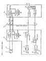
- a portable radio telephone deviceAs shown in Fig. 2, a portable radio telephone device according to an embodiment of the present invention has certain components identical to those of the conventional portable radio telephone device shown in Fig. 1. Those identical components are denoted by identical reference numerals in Fig. 1.
- a curled cord cable 4 interconnecting a microphone-speaker/headphone set 3 and a main telephone unit 5includes a voice signal ground line 21.
- the microphone-speaker/headphone set 3has a capacitor 20C connected at an end thereof to the voice signal ground line 21 and at the other end thereof to non-inverting input terminals of the transmitter amplifier 8 and the receiver amplifier 9 through respective resistors 16R, 18R.
- Resistors 17R, 19Rare connected between the reference output voltage terminal of the bias voltage circuit 7 and the non-inverting input terminals of the transmitter amplifier 8 and the receiver amplifier 9, respectively.
- the transmitter amplifier 8 and the receiver amplifier 9serve as differential amplifiers for amplifying the difference between an AC component on the voice signal ground line 21 and the transmitted and received voice signals, respectively.
- the portable radio telephone devicehas a voice signal ground line connected to the ground terminal of the main telephone unit for adding an AC component on the voice signal ground line to the reference output voltage from the bias voltage circuit of the microphone-speakerlheadphone set, and the voice signal ground line is connected to the non-inverting input terminals of the transmitter and receiver amplifiers, which function as differential amplifiers for amplifying the difference between the AC component on the voice signal ground line and the transmitted and received voice signals, respectively.
- the transmitter and receiver amplifiers connected to the main telephone unit for amplifying the transmitted and received voice signalsfunction as differential amplifiers for amplifying the difference between the AC component on the voice signal ground line and the transmitted and received voice signals, respectively, thereby cancelling the noise caused by the variations in the ground level.
Landscapes
- Engineering & Computer Science (AREA)
- Signal Processing (AREA)
- Telephone Set Structure (AREA)
- Mobile Radio Communication Systems (AREA)
Description
- The present invention relates to a portable radiotelephone device, and more particularly to a portableradio telephone device for use on an automobile.
- Fig. 1 of the accompanying drawings shows aconventional portable radio telephone device for use on anautomobile.
- As shown in Fig. 1, the conventional portable radiotelephone device generally comprises a main telephone unit5a and a microphone-speaker/headphone set 3a connected tothe main telephone unit 5a by a curled cord cable 4a andpowered by a car battery 1 mounted on the automobile. Anexample of this type of portable radio telephone device isdescribed in US5367556.
- The microphone-speaker/headphone set 3a comprises a
power source 6 connected to the car battery 1 forsupplying electric energy to the main telephone unit 5a, abias voltage circuit 7 connected to thepower source 6, atransmitter amplifier 8 having an output terminalconnected to a transmitted voice signal input terminal ofthe main telephone unit 5a, thetransmitter amplifier 8receiving a reference output voltage from thebias voltagecircuit 7, a receiver amplifier 9 having an invertinginput terminal connected to a received voice signal outputterminal of the main telephone unit 5a, the receiver amplifier 9 receiving the reference output voltage fromthebias voltage circuit 7, amicrophone amplifier 10having an input terminal connected to amicrophone 12 andan output terminal connected to an inverting inputterminal of thetransmitter amplifier 8, and aspeakeramplifier 11 having an output terminal connected to aspeaker 13 and an input terminal connected to an outputterminal of the receiver amplifier 9. Thepower source 6,thetransmitter amplifier 8, the receiver amplifier 9, anda power source ground terminal are connected through thecurled cord cable 4a to the main telephone unit 5a. - If noise produced by a
generator 2 on the automobileis applied to the car battery 1, then when the maintelephone unit 5a is transmitting a voice signal, since alarge current flows through the curled cord cable 4a tothe main telephone unit 5a, a voltage drop is developedacross the curled cord cable 4a due to its impedance Z,and hence the ground level of the main telephone unit 5avaries periodically in timed relation to the added noise,as compared with the ground level of the microphone-speaker/headphoneset 3a. The ground level of themicrophone-speaker/ headphone set 3a as viewed from theground level of the main telephone unit 5a variesperiodically in timed relation to the added noise.Therefore, a transmitted voice signal delivered from thetransmitter amplifier 8 to the main telephone unit 5acontains noise representing the variations of the groundlevel within the main telephone unit 5a. As a result, the noise may be heard by the party to which the voice signalis transmitted from a radio transmitter andreceiver 14 ofthe main telephone unit 5a. - Similarly, because ground level of the main telephoneunit 5a as viewed from the ground level of the microphone-speaker/headphoneset 3a varies periodically in timedrelation to the added noise, a received voice signaldelivered from the main telephone unit 5a to the receiveramplifier 9 contains noise representing the variations ofthe ground level within the microphone-speaker/headphoneset 3a. Consequently, the noise is heard from the
speaker 13. - If the main telephone unit 5a is of a digital circuitarrangement, then a large current flows periodicallythrough the curled cord cable 4a because of intermittentsignal transmission between the main telephone unit 5a andthe microphone-speaker/headphone set 3a. Inasmuch as avoltage drop is developed across the curled cord cable 4adue to its impedance Z, the ground level of themicrophone-speaker/headphone set 3a and the main telephoneunit 5a varies periodically in timed relation to theintermittent signal transmission. As a consequence, noisewill also be heard by the party to which the voice signalis transmitted from the main telephone unit 5a and alsoheard from the
speaker 13. - According to a preferred embodiment of the presentinvention, there is provided a portable radio telephonedevice comprising a main telephone unit having a radiotransmitter and receiver and a microphone-speaker/headphoneset connected to the main telephone unitby a curled cord cable, the microphone-speaker/headphoneset comprising a power source connected to a car batteryfor supplying electric energy to the main telephone unit,a bias voltage circuit connected to the power source, atransmitter amplifier having an output terminal connectedto a transmitted voice signal input terminal of the maintelephone unit, the transmitter amplifier receiving areference output voltage from the bias voltage circuit, areceiver amplifier having an inverting input terminalconnected to a received voice signal output terminal ofthe main telephone unit, the receiver amplifier receivingthe reference output voltage from the bias voltagecircuit, a microphone amplifier having an input terminalconnected to a microphone and an output terminal connectedto an inverting input terminal of the-transmitteramplifier, and a speaker amplifier having an outputterminal connected to a speaker and an input terminalconnected to an output terminal of the receiver amplifier,the power source, the transmitter amplifier, the receiveramplifier, and a power source ground terminal beingconnected through the curled cord cable to the main main telephone unit, for adding an AC component thereon tothe reference output voltage from the bias voltagecircuit, the voice signal ground line being connected tonon-inverting input terminal of the transmitter amplifierand the receiver amplifier.
- According to a further embodiment of the presentinvention, the microphonespeaker/headphone set further comprises acapacitor connected at an end thereof to the voice signalground line, first and second resistors connected betweenanother end of the capacitor and non-inverting inputterminals of the transmitter amplifier and the receiveramplifier, respectively, and third and fourth resistorsconnected between a reference output voltage terminal ofthe bias voltage circuit and the non-inverting inputterminals of the transmitter amplifier and the receiveramplifier, respectively.
- The above and other objects, features, and advantagesof the present invention will become apparent from thefollowing description with reference to the accompanyingdrawings which illustrate an example of the presentinvention.
- Fig. 1 is a block diagram of a conventional portableradio telephone device; and
- Fig. 2 is a block diagram of a portable radiotelephone device according to an embodiment of the presentinvention.
- As shown in Fig. 2, a portable radio telephone deviceaccording to an embodiment of the present invention hascertain components identical to those of the conventionalportable radio telephone device shown in Fig. 1. Thoseidentical components are denoted by identical referencenumerals in Fig. 1.
- The portable radio telephone device according to theembodiment of the present invention differs from theconventional portable radio telephone device shownin Fig. 1 as follows: A
curled cord cable 4interconnecting a microphone-speaker/headphone set 3 and amain telephone unit 5 includes a voicesignal ground line 21. The microphone-speaker/headphone set 3 has acapacitor 20C connected at an end thereof to the voicesignal ground line 21 and at the other end thereof to non-invertinginput terminals of thetransmitter amplifier 8and the receiver amplifier 9 through respective resistors16R, 18R.Resistors 17R, 19R are connected between thereference output voltage terminal of thebias voltagecircuit 7 and the non-inverting input terminals of thetransmitter amplifier 8 and the receiver amplifier 9,respectively. Thetransmitter amplifier 8 and thereceiver amplifier 9 serve as differential amplifiers foramplifying the difference between an AC component on thevoicesignal ground line 21 and the transmitted andreceived voice signals, respectively. - In the microphone-speaker/headphone set 3, periodicvariations (AC component) in the ground level of the
maintelephone unit 5 as viewed from the ground level of themicrophone-speaker/headphone set 3 are added to atransmitted voice signal by thetransmitter amplifier 8.In themain telephone unit 5, the noise is cancelled fromthe transmitted voice signal from thetransmitteramplifier 8. - Similarly, periodic variations (AC component) in theground level of the
main telephone unit 5 as viewed fromthe ground level of the microphonespeaker/headphone set 3are added to a received voice signal transmitted from themain telephone unit 5 by the receiver amplifier 9.Therefore, the noise is cancelled from the received voicesignal outputted from the receiver amplifier 9. - According to this embodiment of the presentinvention, as described above, the portable radiotelephone device has a voice signal ground line connectedto the ground terminal of the main telephone unit foradding an AC component on the voice signal ground line tothe reference output voltage from the bias voltage circuitof the microphone-speakerlheadphone set, and the voicesignal ground line is connected to the non-inverting inputterminals of the transmitter and receiver amplifiers,which function as differential amplifiers for amplifyingthe difference between the AC component on the voicesignal ground line and the transmitted and received voicesignals, respectively. Accordingly, even when periodic level variations are developed between the ground levelsof the main telephone unit and the microphone-speaker/headphoneset due to noise from the generator onthe automobile and intermittent signal transmissionbetween the main telephone unit and the microphone-speakerlheadphoneset, the transmitter and receiveramplifiers connected to the main telephone unit foramplifying the transmitted and received voice signalsfunction as differential amplifiers for amplifying thedifference between the AC component on the voice signalground line and the transmitted and received voicesignals, respectively, thereby cancelling the noise causedby the variations in the ground level.
Claims (2)
- A portable radio telephone device comprising:a main telephone unit (5) having a radio transmitterand receiver (14); anda microphone-speaker/headphone set (3) connected tosaid main telephone unit by a curled cord cable (4);said microphone-speaker/headphone set comprising:a power source (6) connected to a car battery forsupplying electric energy to said main telephone unit;a bias voltage circuit (7) connected to said powersource;a transmitter amplifier (8) having an output terminalconnected to a transmitted voice signal input terminal ofsaid main telephone unit, said transmitter amplifierreceiving a reference output voltage (Vref) from said biasvoltage circuit;a receiver amplifier (9) having an inverting inputterminal connected to a received voice signal outputterminal of said main telephone unit, said receiveramplifier receiving the reference output voltage (Vref)from said bias voltage circuit;a microphone amplifier (10) having an input terminalconnected to a microphone (12) and an output terminalconnected to an inverting input terminal of saidtransmitter amplifier (8); anda speaker amplifier (11) having an output terminalconnected to a speaker (13) and an input terminalconnected to an output terminal of said receiveramplifier (9);said power source (6), said transmitter amplifier(8), said receiver amplifier (9), and a power sourceground terminal being connected through said curled cordcable (4) to said main telephone unit (5);said curled cord cable including a voice signalground line (21) connected to a ground terminal of saidmain telephone unit, for adding an AC component thereon tothe reference output voltage from said bias voltagecircuit, said voice signal ground line being connected tonon-inverting input terminal of said transmitter amplifier(8) and said receiver amplifier (9).
- A portable radio telephone device according to claim1 wherein:said microphone-speaker/headphone set furthercomprises:a capacitor (20C) connected at an end thereof to saidvoice signal ground line;first and second resistors (18, 16R) connectedbetween another end of said capacitor and non-invertinginput terminals of said transmitter amplifier and saidreceiver amplifier, respectively; andthird and fourth resistors (17, 19R) connectedbetween a reference output voltage terminal of said biasvoltage circuit and the non-inverting input terminals ofsaid transmitter amplifier and said receiver amplifier,respectively.
Applications Claiming Priority (3)
| Application Number | Priority Date | Filing Date | Title |
|---|---|---|---|
| JP85137/95 | 1995-04-11 | ||
| JP7085137AJP2648125B2 (en) | 1995-04-11 | 1995-04-11 | Mobile phone |
| JP8513795 | 1995-04-11 |
Publications (3)
| Publication Number | Publication Date |
|---|---|
| EP0738047A2 EP0738047A2 (en) | 1996-10-16 |
| EP0738047A3 EP0738047A3 (en) | 2001-05-09 |
| EP0738047B1true EP0738047B1 (en) | 2003-01-22 |
Family
ID=13850273
Family Applications (1)
| Application Number | Title | Priority Date | Filing Date |
|---|---|---|---|
| EP96302542AExpired - LifetimeEP0738047B1 (en) | 1995-04-11 | 1996-04-11 | Portable radio telephone device |
Country Status (4)
| Country | Link |
|---|---|
| US (1) | US5745859A (en) |
| EP (1) | EP0738047B1 (en) |
| JP (1) | JP2648125B2 (en) |
| AU (1) | AU696719B2 (en) |
Families Citing this family (14)
| Publication number | Priority date | Publication date | Assignee | Title |
|---|---|---|---|---|
| US6381454B1 (en)* | 1995-10-10 | 2002-04-30 | Qualcomm Incorporated | Method and system for over-the-air (OTA) service programming |
| DE19545762C1 (en)* | 1995-12-07 | 1997-04-24 | Siemens Ag | Operating condition detection system for cordless mobile telephone |
| US6470197B1 (en) | 1997-08-29 | 2002-10-22 | Veijo Matias Tuoriniemi | Headset control system for operating a microcontroller based device |
| KR100557155B1 (en)* | 1998-11-07 | 2006-06-07 | 삼성전자주식회사 | Circuit for controlling the built-in earphone-microphone connection in portable wireless terminal |
| US6574417B1 (en)* | 1999-08-20 | 2003-06-03 | Thomson Licensing S.A. | Digital video processing and interface system for video, audio and ancillary data |
| US6795718B2 (en) | 2002-02-15 | 2004-09-21 | Youngbo Engineering, Inc. | Headset communication device |
| USD471898S1 (en) | 2002-02-15 | 2003-03-18 | Youngbo Engineering, Inc. | Wireless headset |
| US6760459B2 (en) | 2002-02-15 | 2004-07-06 | Youngbo Engineering, Inc. | Method for securing a headset |
| US9112583B2 (en)* | 2006-09-14 | 2015-08-18 | Symbol Technologies, Llc | Mitigating audible cross talk |
| US20100056096A1 (en)* | 2008-08-29 | 2010-03-04 | Sony Ericsson Mobile Communications Ab | Method for driving a ground reference on a signal path, control circuit for driving a ground reference on a signal path, and mobile device |
| US20100073079A1 (en)* | 2008-09-24 | 2010-03-25 | Sony Ericsson Mobile Communications Ab | Bias arrangement and apparatus |
| JP5958033B2 (en)* | 2012-04-10 | 2016-07-27 | ブラザー工業株式会社 | Voice communication terminal |
| JP6821126B2 (en)* | 2017-05-19 | 2021-01-27 | 株式会社Jvcケンウッド | Noise removal device, noise removal method and noise removal program |
| TWI763028B (en)* | 2020-09-08 | 2022-05-01 | 瑞昱半導體股份有限公司 | Method and audio receiver capable of effectively reducing or avoiding current noise |
Family Cites Families (3)
| Publication number | Priority date | Publication date | Assignee | Title |
|---|---|---|---|---|
| US5265158A (en)* | 1989-05-25 | 1993-11-23 | Nokia Mobile Phones Ltd. | Construction of a stand alone portable telephone unit |
| US5191602A (en)* | 1991-01-09 | 1993-03-02 | Plantronics, Inc. | Cellular telephone headset |
| JPH04239251A (en)* | 1991-01-11 | 1992-08-27 | Toshiba Corp | Radio telephony equipment adaptor |
- 1995
- 1995-04-11JPJP7085137Apatent/JP2648125B2/ennot_activeExpired - Fee Related
- 1996
- 1996-04-03USUS08/627,064patent/US5745859A/ennot_activeExpired - Fee Related
- 1996-04-10AUAU50595/96Apatent/AU696719B2/ennot_activeCeased
- 1996-04-11EPEP96302542Apatent/EP0738047B1/ennot_activeExpired - Lifetime
Also Published As
| Publication number | Publication date |
|---|---|
| AU696719B2 (en) | 1998-09-17 |
| JPH08288899A (en) | 1996-11-01 |
| AU5059596A (en) | 1996-10-24 |
| EP0738047A2 (en) | 1996-10-16 |
| US5745859A (en) | 1998-04-28 |
| JP2648125B2 (en) | 1997-08-27 |
| EP0738047A3 (en) | 2001-05-09 |
Similar Documents
| Publication | Publication Date | Title |
|---|---|---|
| US5802167A (en) | Hands-free device for use with a cellular telephone in a car to permit hands-free operation of the cellular telephone | |
| EP0738047B1 (en) | Portable radio telephone device | |
| US5991420A (en) | Battery pack with audio coil | |
| US6349223B1 (en) | Universal hand-free system for cellular phones in combination with vehicle's audio stereo system | |
| US4491694A (en) | Telephone to stereo amplifier interface coupling | |
| US6173195B1 (en) | Wireless mobile telephone adapter for automobiles | |
| JPH0621730A (en) | Weak power amplifier / transducer driver with signal extension | |
| US4782524A (en) | Telephone headset interface circuit | |
| GB916545A (en) | Improvements in or relating to loud speaking telephone sets | |
| US4599491A (en) | Apparatus for converting direct coupled data devices to acoustic coupled data devices | |
| US7096047B2 (en) | Electronic audio accessory for use with automotive stereo loudspeakers | |
| EP1536663A1 (en) | Headset interface circuit | |
| KR960009436A (en) | Sidetone Reduction Circuit and Method in Receive Signal Path | |
| JPH07231293A (en) | Mobile communication battery charging method | |
| US4518829A (en) | Two terminal microphone active load gain regulation circuit | |
| JP2894882B2 (en) | Hands-free telephone equipment | |
| JPH10174194A (en) | Hearing Aid Adapter for Mobile Phone | |
| KR100419190B1 (en) | Portable infrared rays transmitter | |
| KR930002582B1 (en) | Apparatus in a loud speaking telephone set for supplying power to an amplifier connected to the lond speaker | |
| US5251257A (en) | 2-wire/3-wire converting apparatus | |
| JPH03136418A (en) | two-part radiotelephone | |
| JP3605265B2 (en) | Loudspeaker | |
| JPH11196173A (en) | Communication equipment | |
| KR830001580B1 (en) | Voiceless two-wire simultaneous call device for a loudspeaker | |
| JP3033753B1 (en) | In-vehicle adapter with noise suppression function |
Legal Events
| Date | Code | Title | Description |
|---|---|---|---|
| PUAI | Public reference made under article 153(3) epc to a published international application that has entered the european phase | Free format text:ORIGINAL CODE: 0009012 | |
| AK | Designated contracting states | Kind code of ref document:A2 Designated state(s):GB IT | |
| PUAL | Search report despatched | Free format text:ORIGINAL CODE: 0009013 | |
| AK | Designated contracting states | Kind code of ref document:A3 Designated state(s):GB IT | |
| RIC1 | Information provided on ipc code assigned before grant | Free format text:7H 04B 1/38 A, 7H 04M 1/60 B | |
| 17P | Request for examination filed | Effective date:20010924 | |
| 17Q | First examination report despatched | Effective date:20011115 | |
| GRAG | Despatch of communication of intention to grant | Free format text:ORIGINAL CODE: EPIDOS AGRA | |
| GRAG | Despatch of communication of intention to grant | Free format text:ORIGINAL CODE: EPIDOS AGRA | |
| GRAH | Despatch of communication of intention to grant a patent | Free format text:ORIGINAL CODE: EPIDOS IGRA | |
| GRAH | Despatch of communication of intention to grant a patent | Free format text:ORIGINAL CODE: EPIDOS IGRA | |
| GRAA | (expected) grant | Free format text:ORIGINAL CODE: 0009210 | |
| AK | Designated contracting states | Kind code of ref document:B1 Designated state(s):GB IT | |
| REG | Reference to a national code | Ref country code:GB Ref legal event code:FG4D | |
| PLBE | No opposition filed within time limit | Free format text:ORIGINAL CODE: 0009261 | |
| STAA | Information on the status of an ep patent application or granted ep patent | Free format text:STATUS: NO OPPOSITION FILED WITHIN TIME LIMIT | |
| 26N | No opposition filed | Effective date:20031023 | |
| PGFP | Annual fee paid to national office [announced via postgrant information from national office to epo] | Ref country code:GB Payment date:20060405 Year of fee payment:11 | |
| PGFP | Annual fee paid to national office [announced via postgrant information from national office to epo] | Ref country code:IT Payment date:20060430 Year of fee payment:11 | |
| GBPC | Gb: european patent ceased through non-payment of renewal fee | Effective date:20070411 | |
| PG25 | Lapsed in a contracting state [announced via postgrant information from national office to epo] | Ref country code:GB Free format text:LAPSE BECAUSE OF NON-PAYMENT OF DUE FEES Effective date:20070411 | |
| PG25 | Lapsed in a contracting state [announced via postgrant information from national office to epo] | Ref country code:IT Free format text:LAPSE BECAUSE OF NON-PAYMENT OF DUE FEES Effective date:20070411 |