EP0737285B1 - Multpile valve manifold for use with a pressure sensing apparatus - Google Patents
Multpile valve manifold for use with a pressure sensing apparatusDownload PDFInfo
- Publication number
- EP0737285B1 EP0737285B1EP94907471AEP94907471AEP0737285B1EP 0737285 B1EP0737285 B1EP 0737285B1EP 94907471 AEP94907471 AEP 94907471AEP 94907471 AEP94907471 AEP 94907471AEP 0737285 B1EP0737285 B1EP 0737285B1
- Authority
- EP
- European Patent Office
- Prior art keywords
- manifold
- valve
- chamber
- outlet
- inlet
- Prior art date
- Legal status (The legal status is an assumption and is not a legal conclusion. Google has not performed a legal analysis and makes no representation as to the accuracy of the status listed.)
- Expired - Lifetime
Links
Images


Classifications
- F—MECHANICAL ENGINEERING; LIGHTING; HEATING; WEAPONS; BLASTING
- F16—ENGINEERING ELEMENTS AND UNITS; GENERAL MEASURES FOR PRODUCING AND MAINTAINING EFFECTIVE FUNCTIONING OF MACHINES OR INSTALLATIONS; THERMAL INSULATION IN GENERAL
- F16K—VALVES; TAPS; COCKS; ACTUATING-FLOATS; DEVICES FOR VENTING OR AERATING
- F16K27/00—Construction of housing; Use of materials therefor
- F16K27/02—Construction of housing; Use of materials therefor of lift valves
- F16K27/0263—Construction of housing; Use of materials therefor of lift valves multiple way valves
- F—MECHANICAL ENGINEERING; LIGHTING; HEATING; WEAPONS; BLASTING
- F16—ENGINEERING ELEMENTS AND UNITS; GENERAL MEASURES FOR PRODUCING AND MAINTAINING EFFECTIVE FUNCTIONING OF MACHINES OR INSTALLATIONS; THERMAL INSULATION IN GENERAL
- F16K—VALVES; TAPS; COCKS; ACTUATING-FLOATS; DEVICES FOR VENTING OR AERATING
- F16K11/00—Multiple-way valves, e.g. mixing valves; Pipe fittings incorporating such valves
- F16K11/10—Multiple-way valves, e.g. mixing valves; Pipe fittings incorporating such valves with two or more closure members not moving as a unit
- F16K11/20—Multiple-way valves, e.g. mixing valves; Pipe fittings incorporating such valves with two or more closure members not moving as a unit operated by separate actuating members
- F16K11/22—Multiple-way valves, e.g. mixing valves; Pipe fittings incorporating such valves with two or more closure members not moving as a unit operated by separate actuating members with an actuating member for each valve, e.g. interconnected to form multiple-way valves
- G—PHYSICS
- G01—MEASURING; TESTING
- G01L—MEASURING FORCE, STRESS, TORQUE, WORK, MECHANICAL POWER, MECHANICAL EFFICIENCY, OR FLUID PRESSURE
- G01L19/00—Details of, or accessories for, apparatus for measuring steady or quasi-steady pressure of a fluent medium insofar as such details or accessories are not special to particular types of pressure gauges
- G01L19/0007—Fluidic connecting means
- G01L19/0015—Fluidic connecting means using switching means
- Y—GENERAL TAGGING OF NEW TECHNOLOGICAL DEVELOPMENTS; GENERAL TAGGING OF CROSS-SECTIONAL TECHNOLOGIES SPANNING OVER SEVERAL SECTIONS OF THE IPC; TECHNICAL SUBJECTS COVERED BY FORMER USPC CROSS-REFERENCE ART COLLECTIONS [XRACs] AND DIGESTS
- Y10—TECHNICAL SUBJECTS COVERED BY FORMER USPC
- Y10T—TECHNICAL SUBJECTS COVERED BY FORMER US CLASSIFICATION
- Y10T137/00—Fluid handling
- Y10T137/8158—With indicator, register, recorder, alarm or inspection means
- Y10T137/8175—Plural
- Y—GENERAL TAGGING OF NEW TECHNOLOGICAL DEVELOPMENTS; GENERAL TAGGING OF CROSS-SECTIONAL TECHNOLOGIES SPANNING OVER SEVERAL SECTIONS OF THE IPC; TECHNICAL SUBJECTS COVERED BY FORMER USPC CROSS-REFERENCE ART COLLECTIONS [XRACs] AND DIGESTS
- Y10—TECHNICAL SUBJECTS COVERED BY FORMER USPC
- Y10T—TECHNICAL SUBJECTS COVERED BY FORMER US CLASSIFICATION
- Y10T137/00—Fluid handling
- Y10T137/8593—Systems
- Y10T137/87249—Multiple inlet with multiple outlet
- Y—GENERAL TAGGING OF NEW TECHNOLOGICAL DEVELOPMENTS; GENERAL TAGGING OF CROSS-SECTIONAL TECHNOLOGIES SPANNING OVER SEVERAL SECTIONS OF THE IPC; TECHNICAL SUBJECTS COVERED BY FORMER USPC CROSS-REFERENCE ART COLLECTIONS [XRACs] AND DIGESTS
- Y10—TECHNICAL SUBJECTS COVERED BY FORMER USPC
- Y10T—TECHNICAL SUBJECTS COVERED BY FORMER US CLASSIFICATION
- Y10T137/00—Fluid handling
- Y10T137/8593—Systems
- Y10T137/877—With flow control means for branched passages
- Y10T137/87885—Sectional block structure
Definitions
- the present inventionrelates to a multiple valve manifold for use with a pressure sensing apparatus.
- Fluid pipeline systemsoften require the measurement of pressure or flow characteristics within a given section of a pipeline.
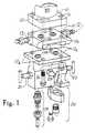
- Reference numeral 10designates a "smart" pressure transmitter the structure of which is not a part of the present invention.
- the transmitter 10is provided with four threaded holes 11.
- a so-called co-planar flange 12provides the diverting function of the 1 1 ⁇ 4 " centres at the transmitter housing 10 to the existing spacing of 21 ⁇ 8" at the high and low pressure inlets of system fluid.
- the co-planar flange 12is thus in fact a diverting attachment to the new transmitter 10. It also provides drain or vent valves 13 and 14 for high pressure and low pressure sides of the transmitter.
- the sealing between the co-planar flange 12 and the transmitter housing 10is accomplished by the use of two seal rings 15 which are spaced at 11 ⁇ 4" centres corresponding to the centres of inlet ports of the transmitter 10.
- a manifold 16is attached to the co-planar flange 12 by means of four mounting bolts of which only two bolts 17 are shown in Figure 1.
- the bolts 17pass through the bolt passages 17a in the upper part of the manifold 16, through bolt passages 17b in the coplanar flange 12 and into the threaded holes 11.
- seal rings 18disposed at the 21 ⁇ 8" centres, are disposed between the manifold 16 and the co-planar flange 12 to provide a hermetical engagement between the two.
- process fluid inlet assemblies 19 or 20Secured to the underside of the manifold body 16 are process fluid inlet assemblies 19 or 20. Two different inlet assemblies are shown in Figure 1. Since they are well known in the art, they do not have to be described in detail.
- Reference numeral 21 and 22designates so-called block or shut-off valves adapted to block the passage of process fluid to the high and low pressure sections of the transmitter housing 10.
- An equalizer valve 23is designed to interconnect the high and low pressure passages with each other.
- the drain or vent valves 13 and 14serve the purpose of venting or draining either the high or the low pressure processed fluid or both.
- the arrangementrequires a substantial space between the process fluid inlet assemblies and the inlet ports of the pressure transmitter.
- the multiple valve manifold according to the features of the preamble of claim 1is well-known in this technical field.
- the present inventionprovides a multiple valve manifold for use with a process fluid pressure sensing apparatus, including a manifold block provided with process fluid inlet means and process fluid outlet means, said outlet means being provided in a normally generally horizontal upper face of said manifold block, said block comprising passage means for selectively opening or blocking the communication between said inlet means and said outlet means, and vent passage means for selectively connecting the outlet means with a vent outlet of said block, characterized in that
- the axes of the actuating stem portionsare generally parallel with the second face section and are located in a general coincidence with an intermediate reference plane generally parallel with said second face and generally equidistantly spaced from the first and second face sections.
- the spacing between the high and low pressure inletsis different from that of the high and low pressure outlets.
- the five valve manifold of the present inventioncomprises an integral body 25.
- the bodyhas a first face section 26 and a second face section 27.
- the first and second face sections 26 and 27are generally parallel with each other.
- the first face section 26is provided with a threaded high pressure inlet 28 which is adapted to receive a connecting assembly such as assembly 29 shown in Figure 2.
- arrangementcan be made for mounting bores which would be compatible with a so called football flange 30 having a threaded hole for receiving the threaded end 31 of a low pressure pipe 32.
- FIG. 2show an arrangement which is only suitable for connection with the assembly 29.
- the periphery of the body 25is comprised of wall portions ( Figure 3) 33-40.
- the wall portions 33-40are summarily referred to as "a peripheral wall section".
- Figure 3shows that the peripheral wall section defines a slightly elongated octagon, it being understood that the actual configuration of the contour of the peripheral wall section is optional.
- the distance between the first and second faces 26, 27is smaller than the width (distance between wall portions 36 and 40) or the length (the distance between the wall portions 34, 38) of the body 25.
- a passage systemwhich includes the already mentioned high pressure inlet 28 for the process flow, a high pressure outlet 41 having the shape of a shallow cylindric recess or chamber in the second face section 27, a low pressure inlet 42 for the process flow and a low pressure outlet 43 having a structure similar to that of the high pressure outlet 41, including the shape of a shallow cylindric recess or chamber.
- the outlets 41, 43are designated as being outlets "for the instrument flow" which means in the context of the present application that the flow active in these outlets is active in transmitting the pressure value to a respective instrument.
- the spacing between the centres of the high and low pressure outlets 41, 43corresponds to that of the instrument housing 44 (the housing shown only in Figure 2). In the embodiment shown, the spacing between the cylindric chambers 41 and 43 is smaller than that between the inlet ports 28, 42. The spacing is selected to accommodate the standard tolerance in the industry.
- the second face section 27is sealingly compatible with respect to the inlet portion of the housing 44.
- the sealing compatibilityis due to seal rings (not shown) and by the provision of mounting holes or passages 45 the spacing of which matches that of the corresponding passages in the housing 44, to receive mounting bolts disposed in threaded bores 46.
- the passages 45do not interfere with any part of the passage system of the manifold.
- the sealing engagementmust be fully hermetical to provide the required accuracy of measurement by the respective instrument.
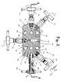
- the manifold of the present inventionis provided with a total of five valves.
- Each valveis of a known structure which includes a valve stem portion disposed inside the body 25 and carrying a valve member. Referring, for instance, to Figure 4, the left-hand valve designated with reference number 47. It is a low pressure block valve. Number 48 designates a high pressure block valve.
- the valvesare of identical structure each carrying, at the free end of the inside valve stem, a conical valve member 49, 50.
- Each valvehas an actuating stem portion projecting outwardly from the wall portions 34 and 38 in opposite directions. The free end of each actuating stem portion is provided with a handle 51, 52, as is well known in the art.
- valves 47, 48In addition to the block valves 47, 48, the manifold body is provided with two equalizer valves 53, 54. One more valve 55 is a vent valve as will be described later. All valves have a structural configuration generally identical to that of valves of 47, 48.
- valves 47, 48, 53-55are spaced from each other about the periphery of the body. They are all located ( Figure 4) within a space limited by a first reference plane P 1 and a second reference plane P 2 , the two planes being generally coincident with the first and second face sections 26, 27.
- the spacing between the high pressure outlet 41 and the low pressure outlet 43is different from the high pressure inlet 28 and the low pressure inlet 42, to accommodate the usual centers of the connecting piping at the first face section 26 and of the housing 44 "smart" transmitter at the second face section 27.
- the outlet 41has the shape of a cylindric chamber.
- the chamberdefines a recess in the second face section 27.
- the depth of the recessis only a fraction of the distance between the face sections 26 and 27.
- the cross-sectional area of chamber 41is a multiple of that of the passages within the body as will be described hereafter.
- reference numeral 56designates a straight discharge portion. Its one end is in a permanent communication with the high pressure outlet chamber 41. The other end of the discharge portion 56 is in a permanent communication with a high pressure valve chamber 57 in which is disposed the valve member 50.
- the cylindric chamber of the low pressure outlet 43communicates with a straight discharge portion 58 extending between the low pressure outlet 43 and a cylindric valve chamber 59 of the low pressure block valve 47, in which is disposed the valve member 49.
- valve chamber 57further communicates with a straight high pressure inlet portion 60 whose end remote from the chamber 57 is in a permanent communication at the high pressure inlet 28 as best seen in Figure 4.
- valve chamber 59communicates with the low pressure inlet 42 by a straight low pressure inlet portion 61.
- Each of the inlet portions 60 and 61defines, at its communication with the respective chamber 57 or 59, a seat for the valve member 50, 49 of the respective shut-off or block valve.
- FIG. 5shows that the cylindric chamber of the high pressure outlet 41 further communicates, by an equalizer passage 62, with a cylindric valve chamber 63 of the equalizer valve 54.
- the part of the passage 62 just before the valve chamber 63is angled to bring the port of the passage 62 at the chamber 63 into coaxial arrangement with the chamber 63.
- Figure 5has the valve 54 removed from chamber 63 for the sake of clarity.
- the manipulation of the high pressure equalization valve 54may selectively open or close the passage 62 and thus the communication with the high pressure outlet chamber 41.
- the valve chamber 63is further in a permanent communication with an equalizer chamber 64 which is provided with a threaded-in plug 65.
- the high pressure equalizer passage extending between the chambers 63 and 64is designated with reference number 66.
- the equalizer chamber 64communicates via a short straight coaxial passage 68 with a valve chamber 69 of the vent valve 55.
- the conical valve member of the vent valve 55may selectively close or open the communication between chambers 64 and 69.
- the valve chamber 69is in permanent communication with an angled vent passage 70 communicating the chamber 69 with a vent outlet 71.
- the vent passage 70 of the embodiment shownis angled to by-pass the mounting opening 45.
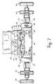
- FIG. 7presents a detail not shown in previous Figures.
- the diagrammatic modification shown in Fig. 7utilizes the same reference numbers for the corresponding parts as those used above, even though some of the designated elements are shown in a slightly modified version.
- Fig. 7presents an improvement, which is intended to solve a problem which is common to all known manifolds of this type.
- air bubblestend to become entrapped in the chambers.
- the entrapment of air bubblesgives rise to inaccuracies in the pressure reading as the reading assumes that the transmission is purely hydraulic.
- reference numeral 25designates the integral body having a first face section 26 and a second face section 27.
- the first face section 26is provided with the high pressure inlet 28 and a low pressure inlet 42.
- the high and low pressure inletscommunicate, in the same fashion as described above, via the associated blocking valves 48, 47, with the cylindric chambers or high and low pressure outlets 41, 43, respectively.
- the communicationis through a passage system which includes, as already mentioned the discharge portion 56 and 58.
- the manifoldis shown fixedly secured to the body housing 44 of the measuring instrument.
- the housing 44 and its partsdo not form a part of the present invention.
- the housing 44includes a high pressure passage 72 and a low pressure passage 73, each generally concentric with the respective cylindric chamber of the outlets 41, 43.
- the passages 72, 73are filled with instrument fluid which is separated from the process fluid, delivered through the manifold, by means isolating diaphragms 74,75.
- the diaphragms 74,75transmit the pressure prevailing in the chambers 41, 43 to the respective parts of the pressure transmitter housing 44, as is well known in the art.
- the diaphragms 74, 75are each disposed at the bottom of an inverse cylindric chamber 76, 77, formed in the lower face of the housing 44.
- the diameter of the chambers 76, 77is the same as that of the respective diaphragm 74, 75.
- the sealssurround each chamber 76, 77 around its periphery to sealingly engage the block or body 25.
- the chamber 41is surrounded by an annular dam 80 and the chamber 43 is similarly surrounded by an annular dam 81.
- the annular dams 80, 81are so arranged that their upper edges project upwardly beyond the second face section 27, to a close proximity of the process fluid side of the respective diaphragm 74, 75.
- the term "close proximity" in the context of the present applicationmeans about 0.4 mm but the actual measurement may depend on the nature of the process fluid and many other considerations.
- the dams 80, 81are continuations of the peripheral walls of the chambers 41, 43. They separate each chamber 41, 43 from the respective annular groove 82, 83 machined in the second face section 27.
- the groove 82forms an end of the equalization or vent passage 62 and the groove 83 likewise communicates with its associated passage 62
- the process fluidis delivered by the manifold from the inlets 28, 42 to the respective outlet chambers 41, 43.
- one of the equalization valvesfor instance, the valve 54 is open to communicate with the equalizer chamber 64.
- the vent valve 55(not shown in Fig. 7) is open.
- the process flowis evacuated from the manifold 25 via the vent outlet 71. If an air bubble is present in the chamber 41, it would distort the reading at the pressure transmitter.
- the incoming pressurized process fluidforces the entrapped air over the dam 80 into the groove 82 and into the passage 62 to eventually reach the vent outlet 71. It has been found out that visual observation of the fluid discharged at 71 is sufficient to determined when the air has been evacuated and the venting can be stopped.
- venting the second chamber 43is analogous with the procedure just described.
- the entire venting of the transmitteris achieved by closing the block valves 47, 48 and opening valves 53, 54 and 55.
- any of the five desired mutual positions of the manifoldcan be achieved. For instance, if it is desired to measure the absolute pressure value at the high pressure inlet, the block valve 47 is closed, the equalizer valve 53 and vent valve 55 open and the equalizer valve 54 closed. If it is desired to vent the high pressure portion of the instrument, the valve 48 is closed and the valves 54 and 55 open. If it is desired to provide both sides of the transmitter with the same pressure (which may be desirable to calibrate the instrument) the valves 48, 54 and 53 are open and the valves 47 and 55 closed.
- the present inventionprovides a simple, reliable and space saving five valve manifold.
- Many other embodiments of the present inventionmay exist which differ from the embodiment disclosed without departing from the present invention. Accordingly, we wish to protect by letters patent which may issue on the present application all such embodiments as fairly fall within the scope of our invention as defined in the appended claims.
Landscapes
- Engineering & Computer Science (AREA)
- General Engineering & Computer Science (AREA)
- Mechanical Engineering (AREA)
- Physics & Mathematics (AREA)
- General Physics & Mathematics (AREA)
- Measuring Fluid Pressure (AREA)
- Valve Housings (AREA)
Abstract
Description
characterized in that
Claims (11)
- A multiple valve manifold for use with a process fluid pressuresensing apparatus, including a manifold block (25) provided with process fluidinlet means (28, 42) and process fluid outlet means (41,43), said outlet means(41, 43) being provided in a normally generally horizontal upper face (27) ofsaid manifold block, said block comprising passage means (60,56, 61, 58) forselectively opening or blocking the communication between said inlet means(28,42) and said outlet means (41, 43), and vent passage means (62, 66, 70) forselectively connecting the outlet means (41,43) with a vent outlet (71) of saidblock,
characterized in that(a) the outlet means is a generally vertical cylindric outlet chamber (41,43)open on top, formed in said upper face (27),(b) the vent passage means includes an upstream end portion having theshape of an annular groove (82, 83) formed in the upper face (27), saidgroove being concentric with and disposed about said cylindric chamber(41,43),(c) an annular dam (80,81) is disposed between the groove (82, 83) and therespective chamber (41, 43), said dam defining a normally generallyhorizontal circular top edge projecting beyond said upper face (27) apredetermined distance which distance selected so as to locate the topedge of the dam (80,81) closely to an isolating diaphragm (74, 75) ofan associated pressure sensing apparatus, when the block (25) issecured to a body (44) of the respective pressure sensing apparatus. - The manifold of claim 1, adapted to be associated with a pressuresensing apparatus in which apparatus the diaphragm (74, 75) forms a bottomof an inverse cylindric chamber (76, 77), characterized in that the outerdiameter of the annular groove (82, 83) corresponds to the diameter of therespective inverse cylindric chamber (76, 77).
- The manifold of claim 1 or claim 2, characterized in that the annulardam (80, 81) is integral with the block (25) and - when the block (25) and the pressure sensing apparatus (44) are assembled, is spaced from thediaphragm by a small distance of about 0.4 mm.
- The manifold of any one of claims 1, 2 or 3, characterized in that itcomprises:(i) a high pressure inlet (28) for a process flow;(ii) a high pressure outlet (41) for the process flow;(iii) a low pressure inlet (42) for the process flow;(iv) a low pressure outlet (43) for the process flow;(v) said vent outlet (71).
- The manifold of any one of claims 1-4, characterized in that itfurther comprises(a) selectively operable valves (47, 48, 53, 54, 55), each having a valvestem portion disposed inside the block (25) and carrying a valve memberand an actuating stem portion projecting outwardly fromthe peripheral wall portion (33, 40) of the body (25);(b) said actuating stem portions being spaced from each other about theperiphery of the body (25) and being all located within a space limitedby a first reference plane (P1) generally coincident with said first facesection (26), and by a second reference plane (P2) generally coincidentwith said upper face section (27).
- The manifold of one of claims 4 or 5, characterized in that thespacing between the high and low pressure inlets (28, 42) is different fromthat of the high and low pressure outlets (41, 43).
- The manifold of one of claims 4-6, characterized in that each outletchamber (41, 43) communicates with one end of a straight discharge portion(56, 58) forming a part of said passage system, the other end of said dischargeportion (56, 58) being in a permanent communication with a cylindric valvechamber (57, 59) of the respective shut-off valve (48, 47).
- The manifold of claim 7 characterized in that each of said shut-offvalve chambers (57, 59) further communicates with one end of a respectivestraight inlet portion (60, 61), the other end of each straight inlet portion (60,61) terminating at the respective inlet (28, 42).
- The manifold of claim 8, characterized in that each pair of respectiveinlet and discharge portions (60-56, 61-58) are disposed at an acute anglerelative to each other, the apex of each acute angle being at the respectivevalve chamber (57, 59).
- The manifold of any one of the preceding claims, characterized inthat(a) each said outlet chamber (41, 43) further communicates with a first endof a respective equalizer passage means (62);(b) the other end of the equalizer passage means (62) being in a permanentcommunication with a respective cylindric equalizer valve chamber (63,67);(c) each equalizer valve chamber (63, 67) further communicating with atransverse passage (66) forming a part of the passage system andpermanently communicating the respective equalizer valve chamber (63,67) with an equalizer chamber (64) disposed generally centrally of theblock (25);(d) each equalizer valve chamber (63, 67) is provided with an equalizervalve (54, 53), a valve member at one end of each respective valvestem portion being compatible with an inlet of said transverse passage(66) to selectively close or open the respective transverse passage atthe respective equalizer valve chamber (63, 67).
- The manifold of claim 10, characterized in that said vent passagemeans includes a vent shut-off valve (55) disposed upstream of said ventoutlet (71), a portion (82-83, 62, 66, 65) of said vent passage means locatedupstream of said vent shut-off valve (55) is a part of said equalizer passagemeans.
Applications Claiming Priority (3)
| Application Number | Priority Date | Filing Date | Title |
|---|---|---|---|
| US24758 | 1993-03-02 | ||
| US08/024,758US5277224A (en) | 1993-03-02 | 1993-03-02 | Five valve manifold for use with a pressure sensing apparatus |
| PCT/CA1994/000100WO1994020777A1 (en) | 1993-03-02 | 1994-03-02 | Five valve manifold for use with a pressure sensing apparatus |
Publications (2)
| Publication Number | Publication Date |
|---|---|
| EP0737285A1 EP0737285A1 (en) | 1996-10-16 |
| EP0737285B1true EP0737285B1 (en) | 1998-12-02 |
Family
ID=21822256
Family Applications (1)
| Application Number | Title | Priority Date | Filing Date |
|---|---|---|---|
| EP94907471AExpired - LifetimeEP0737285B1 (en) | 1993-03-02 | 1994-03-02 | Multpile valve manifold for use with a pressure sensing apparatus |
Country Status (7)
| Country | Link |
|---|---|
| US (1) | US5277224A (en) |
| EP (1) | EP0737285B1 (en) |
| AU (1) | AU6104894A (en) |
| CA (1) | CA2156847A1 (en) |
| DE (1) | DE69415045T2 (en) |
| GB (1) | GB2290830B (en) |
| WO (1) | WO1994020777A1 (en) |
Families Citing this family (56)
| Publication number | Priority date | Publication date | Assignee | Title |
|---|---|---|---|---|
| JPH06505079A (en)* | 1991-03-04 | 1994-06-09 | バルツァース ウント ライボルト ドイチュラント ホールディング アクチエンゲゼルシャフト | Inert gas supply device that supplies inert gas to a multi-stage dry operation type vacuum pump |
| WO1996018091A1 (en) | 1994-12-08 | 1996-06-13 | Rosemount Inc. | Manifold for use with a pressure transmitter |
| US5655560A (en)* | 1994-12-16 | 1997-08-12 | Affymax Technologies N.V. | Clog-free valving system |
| US5725024A (en)* | 1995-09-11 | 1998-03-10 | Pgi International, Ltd. | Manifold valve having controlled vent port integral with flange |
| US5832956A (en)* | 1995-09-25 | 1998-11-10 | Pgi International Ltd. | Three valve controlled vent manifold |
| US6182701B1 (en) | 1995-10-10 | 2001-02-06 | Pgi International, Ltd. | Swivel-type static pressure bar adapter |
| US5709247A (en)* | 1995-12-15 | 1998-01-20 | Hutton; Peter B. | Multiple valve manifold for use with a pressure processing apparatus |
| US5868155A (en)* | 1996-03-13 | 1999-02-09 | Hutton; Peter B. | Valve manifold system |
| USD398375S (en) | 1996-03-29 | 1998-09-15 | Keystone International Holdings Corp. | Manifold |
| US5668322A (en)* | 1996-06-13 | 1997-09-16 | Rosemount Inc. | Apparatus for coupling a transmitter to process fluid having a sensor extension selectively positionable at a plurality of angles |
| US5931192A (en)* | 1996-07-22 | 1999-08-03 | Johnston Pump/General Valve Inc. | External unified integral bleed system for valves |
| US5720317A (en)* | 1996-08-21 | 1998-02-24 | Pgi International, Ltd. | Low profile flanged manifold valve |
| US5906223A (en)* | 1996-09-16 | 1999-05-25 | Itt Industries, Inc. | Chromatography valve assembly |
| TW354371B (en)* | 1997-01-09 | 1999-03-11 | Peter B Hutton | A module valve manifold, a valve module and an integral valve manifold/differential pressure transducer/differential pressure transmitter |
| US5988203A (en)* | 1997-10-01 | 1999-11-23 | Hutton; Peter B. | Two-piece manifold |
| US5823228A (en)* | 1997-02-05 | 1998-10-20 | Keystone International Holdings Corp. | Valve manifold |
| US5771914A (en)* | 1997-02-13 | 1998-06-30 | Baxter International Inc. | Flexible fluid junction |
| SE510074C2 (en)* | 1997-04-04 | 1999-04-19 | Robovalve Ab | Multipath type diaphragm valve |
| US5881766A (en) | 1997-06-06 | 1999-03-16 | Armstrong International, Inc. | Manifold and station for mounting steam/condensate responsive devices in a condensate return line |
| SE513253C2 (en)* | 1997-09-09 | 2000-08-07 | Robovalve Ab | Diaphragm valve and valve housing for a diaphragm valve |
| USD414844S (en) | 1997-10-29 | 1999-10-05 | Tyco Flow Control, Inc. | Manifold |
| USD406320S (en)* | 1997-10-29 | 1999-03-02 | Tyco Flow Control, Inc. | Manifold |
| USD415703S (en)* | 1997-12-04 | 1999-10-26 | Hutton Peter B | Manifold |
| USD407984S (en)* | 1997-12-04 | 1999-04-13 | Hutton Peter B | Manifold |
| USD410398S (en)* | 1997-12-04 | 1999-06-01 | Hutton Peter B | Manifold |
| US6176262B1 (en) | 1998-09-14 | 2001-01-23 | Spencer M. Nimberger | Two-piece manifold system for pressure sensing transmitters |
| US6079443A (en)* | 1998-10-19 | 2000-06-27 | Hutton; Peter B. | Instrument valve manifolds for use with pressure transmitters |
| USD423387S (en)* | 1998-10-19 | 2000-04-25 | Hutton Peter B | Instrument manifolds for use with pressure transmitters |
| US6000427A (en)* | 1998-10-19 | 1999-12-14 | Hutton; Peter B. | Manifold for use with dual pressure sensor units |
| WO2000025049A1 (en) | 1998-10-23 | 2000-05-04 | Chemand Corporation | Fluid handling port array |
| JP3868650B2 (en)* | 1999-02-09 | 2007-01-17 | 株式会社小松製作所 | Hydraulic circuit, priority valve block and operation valve block assembly |
| JP2001304115A (en)* | 2000-04-26 | 2001-10-31 | Toyota Industries Corp | Gas feeding device for vacuum pump |
| US6612618B2 (en)* | 2001-11-16 | 2003-09-02 | Louis Giordano | All-purpose pressure test kit |
| JP4331464B2 (en)* | 2002-12-02 | 2009-09-16 | 株式会社渡辺商行 | Raw material solution supply system to vaporizer and cleaning method |
| US8931519B2 (en)* | 2004-02-19 | 2015-01-13 | Waters Technologies Corporation | Pin valve assembly |
| USD601586S1 (en) | 2004-09-01 | 2009-10-06 | Phoenix Precision | Five valve manifold with angle bonnet |
| US7225832B2 (en)* | 2004-09-01 | 2007-06-05 | Phoenix Precision | Five valve manifold with angle bonnet details |
| US7721764B2 (en)* | 2006-10-13 | 2010-05-25 | Rosemount Inc. | Process pressure measurement system with improved venting |
| US7398695B2 (en)* | 2006-10-27 | 2008-07-15 | Unique Industrial Product Company | Universal converter plate for pressure transmitters |
| JP2008291941A (en)* | 2007-05-25 | 2008-12-04 | Surpass Kogyo Kk | Fluid apparatus unit structure |
| GB2454661A (en)* | 2007-11-13 | 2009-05-20 | Bifold Fluidpower Ltd | Valve manifold |
| GB2457473A (en)* | 2008-02-14 | 2009-08-19 | Bifold Fluidpower Ltd | Isolation valve manifold |
| CN101509563B (en)* | 2009-03-24 | 2011-06-22 | 温州市金星阀门有限公司 | Multifunction multipath multi-control high-pressure needle valve |
| CA2721884A1 (en)* | 2009-11-19 | 2011-05-19 | Peter B. Hutton | Purge manifold |
| CN101943188B (en)* | 2010-04-29 | 2013-08-21 | 上海人豪液压技术有限公司 | Compact two-way cartridge valve adopting combined type flange control cover plate |
| CN101949464A (en)* | 2010-09-10 | 2011-01-19 | 温州市金星阀门有限公司 | Double-off discharging sampling valve |
| CN101963248A (en)* | 2010-09-10 | 2011-02-02 | 温州市金星阀门有限公司 | Double-stop discharge needle-shaped valve |
| US9127858B2 (en) | 2010-11-24 | 2015-09-08 | David Wayne McKeown | Multi-circuit manifold and method for a geothermal energy system |
| GB2493152A (en)* | 2011-07-25 | 2013-01-30 | Aes Eng Ltd | Modular valve with block and bleed functions |
| BR102014023895A2 (en) | 2014-09-25 | 2016-05-17 | Fmc Technologies Do Brasil Ltda | block architecture manifold |
| CN105736764B (en)* | 2016-04-05 | 2018-07-20 | 建德市新安江气动元件有限公司 | A kind of plug-in Integrated valve group and its working method |
| CN108801541A (en)* | 2018-06-21 | 2018-11-13 | 国网福建省电力有限公司检修分公司 | A kind of SF6Pressure gauge structure |
| DE202018107099U1 (en) | 2018-12-12 | 2019-01-04 | Anni Hjorth Blum | Device for measuring the flow of ballast water through a pipeline |
| USD1094488S1 (en)* | 2021-12-10 | 2025-09-23 | Lam Research Corporation | Manifold for supplying coolant to components of substrate processing systems |
| US12416539B2 (en)* | 2022-03-16 | 2025-09-16 | R.J. Machine Company, Inc. | Manifold with inter-opening features for use with a pressure transmitter |
| CN119435766B (en)* | 2025-01-09 | 2025-04-15 | 浙江方顿仪表阀门有限公司 | High-temperature high-pressure double-seal double-regulating needle valve |
Family Cites Families (18)
| Publication number | Priority date | Publication date | Assignee | Title |
|---|---|---|---|---|
| US1797591A (en)* | 1927-05-23 | 1931-03-24 | Wayne Pump Co | Battery of valves |
| US2804879A (en)* | 1953-07-27 | 1957-09-03 | Frank R Hanson | Water distributor |
| US2871881A (en)* | 1957-01-28 | 1959-02-03 | John E Hewson | Valve manifold |
| US3450157A (en)* | 1967-07-31 | 1969-06-17 | John E Hewson | Valve manifold |
| US3633618A (en)* | 1970-02-26 | 1972-01-11 | Joseph J Blackmore | Valved manifold for gauging a plurality of fluid pressures |
| US3768511A (en)* | 1971-11-15 | 1973-10-30 | S Bias | Control device |
| CA990102A (en)* | 1973-06-25 | 1976-06-01 | Sydney C. Bias | Control device |
| US3894559A (en)* | 1974-03-28 | 1975-07-15 | Leland Q Depuy | Manifold valve |
| US4092865A (en)* | 1976-06-24 | 1978-06-06 | Gould Inc. | Fluid-test apparatus |
| US4319492A (en)* | 1980-01-23 | 1982-03-16 | Anderson, Greenwood & Co. | Pressure transmitter manifold |
| US4582089A (en)* | 1984-10-31 | 1986-04-15 | General Screw Products Company | Valve manifold having a removable flange |
| US4602657A (en)* | 1985-02-11 | 1986-07-29 | Anderson-Greenwood & Co. | Valve manifold for a differential pressure transmitter |
| CA1240584A (en)* | 1986-01-28 | 1988-08-16 | Edward R. Coleman | Valve manifold |
| US4977917A (en)* | 1986-06-06 | 1990-12-18 | Adams Don L | Modular differential pressure transmitter/manifold for a fluid conveying pipeline |
| US5117867A (en)* | 1986-06-06 | 1992-06-02 | Adams Don L | Manifold for a differential pressure transmitter |
| US5209258A (en)* | 1987-03-02 | 1993-05-11 | Daniel Flow Products | Apparatus and method for minimizing pulsation-induced errors in differential pressure flow measuring devices |
| DE4004834C2 (en)* | 1990-02-16 | 1996-06-13 | Festo Kg | Valve assembly |
| US5036884A (en)* | 1990-11-19 | 1991-08-06 | Keystone International Holdings Corp. | Mounting means for fluid pressure transmitters |
- 1993
- 1993-03-02USUS08/024,758patent/US5277224A/ennot_activeExpired - Lifetime
- 1994
- 1994-03-02DEDE69415045Tpatent/DE69415045T2/ennot_activeExpired - Fee Related
- 1994-03-02CACA002156847Apatent/CA2156847A1/ennot_activeAbandoned
- 1994-03-02EPEP94907471Apatent/EP0737285B1/ennot_activeExpired - Lifetime
- 1994-03-02WOPCT/CA1994/000100patent/WO1994020777A1/enactiveIP Right Grant
- 1994-03-02GBGB9517496Apatent/GB2290830B/ennot_activeExpired - Fee Related
- 1994-03-02AUAU61048/94Apatent/AU6104894A/ennot_activeAbandoned
Also Published As
| Publication number | Publication date |
|---|---|
| EP0737285A1 (en) | 1996-10-16 |
| DE69415045T2 (en) | 1999-06-10 |
| DE69415045D1 (en) | 1999-01-14 |
| AU6104894A (en) | 1994-09-26 |
| CA2156847A1 (en) | 1994-09-15 |
| GB9517496D0 (en) | 1995-10-25 |
| US5277224A (en) | 1994-01-11 |
| GB2290830A (en) | 1996-01-10 |
| GB2290830B (en) | 1997-11-26 |
| WO1994020777A1 (en) | 1994-09-15 |
Similar Documents
| Publication | Publication Date | Title |
|---|---|---|
| EP0737285B1 (en) | Multpile valve manifold for use with a pressure sensing apparatus | |
| US6675658B2 (en) | Manifold for use with a pressure transmitter | |
| AU714184B2 (en) | Multiple valve manifold for use with a pressure processing apparatus | |
| US5988203A (en) | Two-piece manifold | |
| CA1240584A (en) | Valve manifold | |
| US6000427A (en) | Manifold for use with dual pressure sensor units | |
| US6176262B1 (en) | Two-piece manifold system for pressure sensing transmitters | |
| US5868155A (en) | Valve manifold system | |
| CN1187586C (en) | split manifold | |
| EP1123493B1 (en) | Instrument valve manifolds for use with pressure transmitters | |
| EP0866959B1 (en) | Multiple valve manifold for use with a pressure processing apparatus | |
| MXPA98004668A (en) | Distributor of multiple valves for use with a processing device of pres | |
| US6182701B1 (en) | Swivel-type static pressure bar adapter | |
| MXPA99006393A (en) | Two-piece valve manifold |
Legal Events
| Date | Code | Title | Description |
|---|---|---|---|
| PUAI | Public reference made under article 153(3) epc to a published international application that has entered the european phase | Free format text:ORIGINAL CODE: 0009012 | |
| 17P | Request for examination filed | Effective date:19951214 | |
| AK | Designated contracting states | Kind code of ref document:A1 Designated state(s):DE FR IT NL | |
| 17Q | First examination report despatched | Effective date:19970725 | |
| GRAG | Despatch of communication of intention to grant | Free format text:ORIGINAL CODE: EPIDOS AGRA | |
| GRAG | Despatch of communication of intention to grant | Free format text:ORIGINAL CODE: EPIDOS AGRA | |
| GRAH | Despatch of communication of intention to grant a patent | Free format text:ORIGINAL CODE: EPIDOS IGRA | |
| GRAG | Despatch of communication of intention to grant | Free format text:ORIGINAL CODE: EPIDOS AGRA | |
| GRAG | Despatch of communication of intention to grant | Free format text:ORIGINAL CODE: EPIDOS AGRA | |
| GRAH | Despatch of communication of intention to grant a patent | Free format text:ORIGINAL CODE: EPIDOS IGRA | |
| GRAA | (expected) grant | Free format text:ORIGINAL CODE: 0009210 | |
| AK | Designated contracting states | Kind code of ref document:B1 Designated state(s):DE FR IT NL | |
| REF | Corresponds to: | Ref document number:69415045 Country of ref document:DE Date of ref document:19990114 | |
| ITF | It: translation for a ep patent filed | ||
| ET | Fr: translation filed | ||
| PLBE | No opposition filed within time limit | Free format text:ORIGINAL CODE: 0009261 | |
| STAA | Information on the status of an ep patent application or granted ep patent | Free format text:STATUS: NO OPPOSITION FILED WITHIN TIME LIMIT | |
| 26N | No opposition filed | ||
| PGFP | Annual fee paid to national office [announced via postgrant information from national office to epo] | Ref country code:FR Payment date:20010227 Year of fee payment:8 | |
| PGFP | Annual fee paid to national office [announced via postgrant information from national office to epo] | Ref country code:NL Payment date:20010330 Year of fee payment:8 | |
| PGFP | Annual fee paid to national office [announced via postgrant information from national office to epo] | Ref country code:DE Payment date:20010430 Year of fee payment:8 | |
| PG25 | Lapsed in a contracting state [announced via postgrant information from national office to epo] | Ref country code:NL Free format text:LAPSE BECAUSE OF NON-PAYMENT OF DUE FEES Effective date:20021001 Ref country code:DE Free format text:LAPSE BECAUSE OF NON-PAYMENT OF DUE FEES Effective date:20021001 | |
| PG25 | Lapsed in a contracting state [announced via postgrant information from national office to epo] | Ref country code:FR Free format text:LAPSE BECAUSE OF NON-PAYMENT OF DUE FEES Effective date:20021129 | |
| NLV4 | Nl: lapsed or anulled due to non-payment of the annual fee | Effective date:20021001 | |
| REG | Reference to a national code | Ref country code:FR Ref legal event code:ST | |
| PG25 | Lapsed in a contracting state [announced via postgrant information from national office to epo] | Ref country code:IT Free format text:LAPSE BECAUSE OF NON-PAYMENT OF DUE FEES;WARNING: LAPSES OF ITALIAN PATENTS WITH EFFECTIVE DATE BEFORE 2007 MAY HAVE OCCURRED AT ANY TIME BEFORE 2007. THE CORRECT EFFECTIVE DATE MAY BE DIFFERENT FROM THE ONE RECORDED. Effective date:20050302 |