EP0734988A2 - Method and apparatus for the movement of perforating needles - Google Patents
Method and apparatus for the movement of perforating needlesDownload PDFInfo
- Publication number
- EP0734988A2 EP0734988A2EP96104310AEP96104310AEP0734988A2EP 0734988 A2EP0734988 A2EP 0734988A2EP 96104310 AEP96104310 AEP 96104310AEP 96104310 AEP96104310 AEP 96104310AEP 0734988 A2EP0734988 A2EP 0734988A2
- Authority
- EP
- European Patent Office
- Prior art keywords
- puncture
- cutting
- cylinder
- drive
- puncture needle
- Prior art date
- Legal status (The legal status is an assumption and is not a legal conclusion. Google has not performed a legal analysis and makes no representation as to the accuracy of the status listed.)
- Granted
Links
Images
Classifications
- B—PERFORMING OPERATIONS; TRANSPORTING
- B65—CONVEYING; PACKING; STORING; HANDLING THIN OR FILAMENTARY MATERIAL
- B65H—HANDLING THIN OR FILAMENTARY MATERIAL, e.g. SHEETS, WEBS, CABLES
- B65H45/00—Folding thin material
- B65H45/12—Folding articles or webs with application of pressure to define or form crease lines
- B65H45/16—Rotary folders
- B65H45/162—Rotary folders with folding jaw cylinders
- B65H45/165—Details of sheet gripping means therefor
- Y—GENERAL TAGGING OF NEW TECHNOLOGICAL DEVELOPMENTS; GENERAL TAGGING OF CROSS-SECTIONAL TECHNOLOGIES SPANNING OVER SEVERAL SECTIONS OF THE IPC; TECHNICAL SUBJECTS COVERED BY FORMER USPC CROSS-REFERENCE ART COLLECTIONS [XRACs] AND DIGESTS
- Y10—TECHNICAL SUBJECTS COVERED BY FORMER USPC
- Y10T—TECHNICAL SUBJECTS COVERED BY FORMER US CLASSIFICATION
- Y10T83/00—Cutting
- Y10T83/04—Processes
- Y10T83/0448—With subsequent handling [i.e., of product]
- Y10T83/0467—By separating products from each other
- Y—GENERAL TAGGING OF NEW TECHNOLOGICAL DEVELOPMENTS; GENERAL TAGGING OF CROSS-SECTIONAL TECHNOLOGIES SPANNING OVER SEVERAL SECTIONS OF THE IPC; TECHNICAL SUBJECTS COVERED BY FORMER USPC CROSS-REFERENCE ART COLLECTIONS [XRACs] AND DIGESTS
- Y10—TECHNICAL SUBJECTS COVERED BY FORMER USPC
- Y10T—TECHNICAL SUBJECTS COVERED BY FORMER US CLASSIFICATION
- Y10T83/00—Cutting
- Y10T83/202—With product handling means
- Y10T83/2092—Means to move, guide, or permit free fall or flight of product
- Y10T83/2096—Means to move product out of contact with tool
- Y10T83/21—Out of contact with a rotary tool
- Y10T83/2105—Mover mounted on rotary tool
- Y—GENERAL TAGGING OF NEW TECHNOLOGICAL DEVELOPMENTS; GENERAL TAGGING OF CROSS-SECTIONAL TECHNOLOGIES SPANNING OVER SEVERAL SECTIONS OF THE IPC; TECHNICAL SUBJECTS COVERED BY FORMER USPC CROSS-REFERENCE ART COLLECTIONS [XRACs] AND DIGESTS
- Y10—TECHNICAL SUBJECTS COVERED BY FORMER USPC
- Y10T—TECHNICAL SUBJECTS COVERED BY FORMER US CLASSIFICATION
- Y10T83/00—Cutting
- Y10T83/202—With product handling means
- Y10T83/2092—Means to move, guide, or permit free fall or flight of product
- Y10T83/2183—Product mover including gripper means
- Y10T83/219—Rotating or oscillating product handler
- Y—GENERAL TAGGING OF NEW TECHNOLOGICAL DEVELOPMENTS; GENERAL TAGGING OF CROSS-SECTIONAL TECHNOLOGIES SPANNING OVER SEVERAL SECTIONS OF THE IPC; TECHNICAL SUBJECTS COVERED BY FORMER USPC CROSS-REFERENCE ART COLLECTIONS [XRACs] AND DIGESTS
- Y10—TECHNICAL SUBJECTS COVERED BY FORMER USPC
- Y10T—TECHNICAL SUBJECTS COVERED BY FORMER US CLASSIFICATION
- Y10T83/00—Cutting
- Y10T83/647—With means to convey work relative to tool station
- Y10T83/658—With projections on work-carrier [e.g., pin wheel]
- Y—GENERAL TAGGING OF NEW TECHNOLOGICAL DEVELOPMENTS; GENERAL TAGGING OF CROSS-SECTIONAL TECHNOLOGIES SPANNING OVER SEVERAL SECTIONS OF THE IPC; TECHNICAL SUBJECTS COVERED BY FORMER USPC CROSS-REFERENCE ART COLLECTIONS [XRACs] AND DIGESTS
- Y10—TECHNICAL SUBJECTS COVERED BY FORMER USPC
- Y10T—TECHNICAL SUBJECTS COVERED BY FORMER US CLASSIFICATION
- Y10T83/00—Cutting
- Y10T83/647—With means to convey work relative to tool station
- Y10T83/6584—Cut made parallel to direction of and during work movement
- Y10T83/6635—By feed roller
Definitions
- the inventionrelates to a method and a device for moving pin needles in accordance with the preamble of claim 1.
- DE 38 10 439 C1discloses a folder consisting of a cutting cylinder, puncturing, collecting and folding knife cylinder as well as a folding jaw cylinder, by means of which a paper strand entering between the cutting cylinder and the puncturing, collecting and folding knife cylinder is initially passed through on the puncture -, collecting and folding knife cylinders arranged punctures, cut by cutting knife of the cutting cylinder in connection with cutting bars arranged on the puncturing, collecting and folding knife cylinder in the vicinity of the punctures, the signatures on the puncturing, collecting and folding knife cylinder transported or collected , transported and subsequently handed over to the jaw cylinder.
- puncturesconsist, among other things, of a plurality of puncture needles arranged one behind the other in the axial direction on a control spindle and pivotable in puncture holder arms. These emerge with their needle tips for needling the product according to the production requirements from the periphery of the puncturing, collecting and folding knife cylinder by the spindle, which is mounted on the cylinder, is turned by means of a cam mechanism.
- the needle tips of the puncture needlesdescribe part of a circular path around the axis of rotation of the spindle, which is mounted on the cylinder.
- a disadvantage of these puncturesis that the puncture needles are arranged relatively far from the cutting bar in order to prevent a collision with the cutting edge of the cutting knife.
- a large distance between a separating cut of the paper web and the puncture systems piercing the paper webis disadvantageous with regard to the paper waste when, like in commercial or telephone book printing, an edge strip provided with puncture holes has to be cut off again after production has taken place.
- the inventionhas for its object to provide a method and a device for moving pin needles on the periphery of a cylinder, by means of which a puncture into a product strand near the cutting line of a knife acting against a cutting bar is made possible.
- a transport cylinder 1is mounted on side plates 2 arranged on the end face (second side plate not shown), as well as axle journals (not shown) in side frames (not shown) and has cross members 3 extending in the axis-parallel direction.
- Each traverse 3carries a groove bar 4, which receives a cutting bar 7 on its side directed towards the periphery 6 of the transport cylinder 1, on which a cutting knife 8 of a cutting cylinder, not shown, acts, ie between which a strand-shaped product 24 is cut.
- a puncture holder arm 10is clamped onto a control spindle 9 which is fixedly mounted on the side window, on the free end 11 of which a puncture needle holder 12 is arranged in a form-fitting manner.
- the puncture needle holder 12has a puncture needle 14 at its peripheral end 13.
- the puncture needle holder 12is at its puncture needle end 16 with a drive 17, z. B. connected to a solenoid.
- the puncture needle 14is fastened in a plunger 29 which has a plunger guide 31, which is connected to the solenoid. In the idle state, the plunger 29 is pressed with the puncture needle 14 against the force of a compression spring 32 into an end position directed in the direction of the drive 17.
- the groove strip 4 carried by the crossmember 3 and fastened to the side windows 2each has an opening 18 for each puncture holder arm 10.
- a plurality of puncture holder arms 10, puncture holder 12 and puncture needles 14are arranged on the control spindle 9 at a distance from one another in the manner described above.
- the control spindle 9is at least at one end firmly connected to a roller lever, not shown, which is in a non-positive or positive connection with a side disc-fixed control cam.
- the control spindle 9is designed as a hollow spindle, accommodates in its interior a torsion bar spring 21 which is connected in a rotationally fixed manner to the hollow spindle at one end and is fastened to the side window at the other end, as a result of which the roller lever is always pressed against the control cam.
- the puncture needle 14can emerge from the periphery 6 of the transport cylinder 1 through a slot 22 running in the axis-parallel direction.
- the slot 22can be widened by removing a cover strip 23 (FIG. 1).
- a product strand 24runs in the specified production direction D between the cutting cylinder (not shown) and the one Transport cylinder 1, the product strand 24 being needled by means of the puncture needles 14, which are still in a central position B, and subsequently being cross-separated from the cutting knife 8 acting against the cutting bar 7 of the transport cylinder 1.
- the needle tips 26perform an ascending curve 36 to a central position B (FIG. 2) from their basic position A (FIG. 2) as a result of an arc-shaped pivoting movement E of the puncture holder arm 10 from E1 to E2 (FIG . 1 and 2).
- the center position B of the needle tips 26is in the immediate vicinity of a radial or perpendicular 33, which represents the center line of the cutting knife 8 located in the cutting cylinder at the time the product strand 24 is cut.
- the needle tips 26 of the puncture needles 14each carry out a linear, almost radial movement F of the plunger 29 from F1 to F2 to their end position C. , the needle tips 26 having traveled their longest path after leaving the periphery 6.
- this linear movement F of the puncture needles 14, ie from F1 to F2 (curve 37 according to FIG. 2) from the central position B to the end position Conly slight additional forces act on the products, as a result of which slitting of the puncture holes is avoided.
- the transport cylinder 1not shown folding knife.
- the needle tips 26 of the puncture needles 14are moved from the end position C into the basic position A, which is located within the periphery 6 of the transport cylinder 1, that is to say from F2 returned to E1 without passing through the middle position B (curve 38, FIG. 2).
- the curve 38runs approximately as a straight line with an average angle beta of approximately 40 ° to the radial or perpendicular 33 (FIG. 2). This end of the folded signature is thus released by the puncture needles 14.
- the actuation of the drive 17, for. B. a solenoidcan be located on the transport cylinder 1, not shown power supplies, z. B. slip rings.
- the needle tips 26 of the puncture needles 14cover a path of five to 15 mm, preferably eleven millimeters for thick products, measured in the radial direction of the transport cylinder 1, from their exit from the periphery 6 of the transport cylinder 1 to the maximum position C of the needle tips 26.
- a radial distance from the basic position A to the central position B of the needle tips 26corresponds to two thirds of the radial distance of the needle tips 26 from the basic position A to the maximum position C.
- the drive 17is a reversing lifting magnet.
- the reversing solenoidhas two switching positions, so that a compression spring 32 for the automatic resetting of the plunger 29 can be omitted.
- the drive 17can be designed as any linear drive, for. B as a pneumatic working cylinder with air supply via a rotary entry on the axle journal.
Landscapes
- Folding Of Thin Sheet-Like Materials, Special Discharging Devices, And Others (AREA)
Abstract
Description
Translated fromGermanDie Erfindung betrifft ein Verfahren sowie eine Einrichtung zum Bewegen von Punkturnadeln entsprechend dem Oberbegriff des Anspruches 1.The invention relates to a method and a device for moving pin needles in accordance with the preamble of claim 1.
Durch die DE 38 10 439 C1 ist ein aus Schneidzylinder, Punktur-, Sammel- und Falzmesserzylinder sowie aus einem Falzklappenzylinder bestehender Falzapparat bekannt, mittels welchem ein zwischen dem Schneidzylinder sowie Punktur-, Sammel- und Falzmesserzylinder einlaufender Papierstrang an seinem Anfang durch auf dem Punktur-, Sammel- und Falzmesserzylinder angeordneten Punkturen aufgenadelt, durch Schneidmesser des Schneidzylinders in Verbindung mit auf dem Punktur-, Sammel- und Falzmesserzylinder in der Nähe der Punkturen angeordneten Schneidleisten geschnitten, die Signaturen auf dem Punktur-, Sammel- und Falzmesserzylinder transportiert bzw. gesammelt, transportiert und nachfolgend dem Falzklappenzylinder übergeben werden. Diese Punkturen bestehen u.a. aus mehreren in axialer Richtung hintereinander auf einer Steuerspindel schwenkbar in Punkturhalterarmen angeordneten Punkturnadeln. Diese treten mit ihren Nadelspitzen zum Aufnadeln des Produktes entsprechend den Produktionserfordernissen aus der Peripherie des Punktur-, Sammel- und Falzmesserzylinders heraus, indem die zylinderfest gelagerte Spindel mittels eines Kurvengetriebes verdreht wird. Dabei beschreiben die Nadelspitzen der Punkturnadeln einen Teil einer Kreisbahn um die Rotationsachse der zylinderfest gelagerten Spindel.
Nachteilig bei diesen Punkturen ist es, daß die Punkturnadeln verhältnismäßig weit von der Schneidleiste angeordnet sind, um eine Kollision mit der Schneide des Schneidmesser zu verhindern. Ein großer Abstand zwischen einem Trennschnitt der Papierbahn und der in die Papierbahn einstechenden Punktursysteme ist hinsichtlich des Papierverschnittes dann von Nachteil, wenn wie beim Akzidenz- oder Telefonbuchdruck, ein mit Punkturlöchern versehener Randstreifen nach erfolgter Produktion wieder abgeschnitten werden muß.A disadvantage of these punctures is that the puncture needles are arranged relatively far from the cutting bar in order to prevent a collision with the cutting edge of the cutting knife. A large distance between a separating cut of the paper web and the puncture systems piercing the paper web is disadvantageous with regard to the paper waste when, like in commercial or telephone book printing, an edge strip provided with puncture holes has to be cut off again after production has taken place.
Der Erfindung liegt die Aufgabe zugrunde, ein Verfahren sowie eine Einrichtung zum Bewegen von Punkturnadeln an der Peripherie eines Zylinders zu schaffen, mittels welchen ein Einstich in einen Produktstrang nahe der Schneidlinie eines gegen eine Schneidleiste wirkenden Messers ermöglicht wird.The invention has for its object to provide a method and a device for moving pin needles on the periphery of a cylinder, by means of which a puncture into a product strand near the cutting line of a knife acting against a cutting bar is made possible.
Diese Aufgabe wird erfindungsgemäß durch die im kennzeichnenden Teil der Ansprüche 1 und 4 genannten Merkmale gelöst.
Die mit der Erfindung erzielbaren Vorteile bestehen insbesondere darin, daß zwischen den Punkturlöchern und der Schnittkante des Druckproduktes ein geringer Abstand besteht, ohne daß die Punkturnadeln den Schneidvorgang behindern. Dies ist insbesondere bei Telefonbuch- und Akzidenzdruckmaschinen von Vorteil, da bei der nachfolgenden Bearbeitung der Signaturen dann ein schmalerer Randstreifen abgeschnitten werden kann und somit ein Papierverlust reduziert wird.
Weiterhin ist von Vorteil, daß bei Abgabe der Signaturen von einem Punktur-, Sammel- und Falzmesserzylinder, nachfolgend als Transportzylinder bezeichnet, auf einen Falzklappenzylinder für das bei der Abgabe an den Falzklappenzylinder noch auf dem Transportzylinder befindliche und von den Punkturnadeln gehaltene Ende ein Bewegen der Punkturnadelspitzen in die Rückzugsrichtung des Signaturendes erfolgt, was das "Abnadeln" der Signaturen, d. h. das Zurückziehen der Punkturnadeln erleichtert, so daß ein Schlitzen von Punkturlöchern, ein Beschädigen von Punkturnadeln oder ein Herausziehen der Signaturen aus den Falzklappen des Falzklappenzylinders vermieden wird.This object is achieved by the features mentioned in the characterizing part of
The advantages that can be achieved with the invention are, in particular, that between the puncture holes and there is a small distance between the cut edge of the printed product and the pin needles do not impede the cutting process. This is particularly advantageous in the case of telephone book and commercial printing presses, since a narrower edge strip can then be cut off during the subsequent processing of the signatures and thus paper loss is reduced.
It is also advantageous that when the signatures are delivered from a puncture, collecting and folding knife cylinder, hereinafter referred to as the transport cylinder, to a folding jaw cylinder for moving the end located on the transport cylinder when it is delivered to the folding jaw cylinder and held by the puncture needles Puncture needle tips are in the retraction direction of the signature end, which facilitates the "needling" of the signatures, ie the retraction of the puncture needles, so that slitting of puncture holes, damage to puncture needles or pulling out of the signatures from the jaws of the jaw cylinder is avoided.
Ein Ausführungsbeispiel der Erfindung ist in der Zeichnung dargestellt und wird im folgenden näher beschrieben.An embodiment of the invention is shown in the drawing and will be described in more detail below.
Es zeigen
- Fig. 1
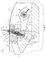
- einen Teil eines Querschnittes eines Transportzylinders mit der schematischen Darstellung eines Punkturantriebes, einer Schneidleiste sowie eines Schneidmessers eines mit dem Transportzylinder zusammenwirkenden Schneidmesserzylinders;
- Fig. 2
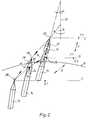
- eine Bewegungsablaufkurve einer Punkturnadelspitze entsprechend der Bewegung des Punkturantriebes nach Fig. 1.
- Fig. 1
- a part of a cross section of a transport cylinder with the schematic Representation of a puncture drive, a cutting bar and a cutting knife of a cutting knife cylinder interacting with the transport cylinder;
- Fig. 2
- 2 shows a movement sequence curve of a puncture needle tip corresponding to the movement of the puncture drive according to FIG. 1.
Ein Transportzylinder 1 ist über stirnseitig angeordnete Seitenscheiben 2 (zweite Seitenscheibe nicht dargestellt), sowie nichtdargestellte Achszapfen in nichtdargestellten Seitengestellen gelagert und weist sich in achsparalleler Richtung erstreckende Traversen 3 auf. Jede Traverse 3 trägt eine Nutleiste 4, welche an ihrer in Richtung Peripherie 6 des Transportzylinders 1 gerichteten Seite eine Schneidleiste 7 aufnimmt, auf welche ein Schneidmesser 8 eines nichtdargestellten Schneidzylinders einwirkt, d. h. zwischen welchen ein strangförmiges Produkt 24 geschnitten wird. Auf einer seitenscheibenfest gelagerten Steuerspindel 9 ist ein Punkturhalterarm 10 festgeklemmt, an dessen freiem Ende 11 ein Punkturnadelhalter 12 formschlüssig angeordnet ist. Der Punkturnadelhalter 12 weist an seinem peripherienahen Ende 13 eine Punkturnadel 14 auf. Der Punkturnadelhalter 12 ist an seinem punkturnadelfernen Ende 16 mit einem Antrieb 17, z. B. einem Hubmagneten verbunden. Dabei ist die Punkturnadel 14 in einem Stößel 29 befestigt, welcher eine Stößelführung 31 aufweist, die mit dem Hubmagneten in Verbindung steht. Im Ruhezustand wird der Stößel 29 mit der Punkturnadel 14 gegen die Kraft einer Druckfeder 32 in eine in Richtung Antrieb 17 gerichtete Endstellung gedrückt. Die von der Traverse 3 getragene und an den Seitenscheiben 2 befestigte Nutleiste 4 weist jeweils einen Durchbruch 18 für jeden Punkturhalterarm 10 auf. Es sind entsprechend den Erfordernissen mehrere Punkturhalterarme 10, Punkturhalter 12 sowie Punkturnadeln 14 in der vorbeschriebenen Art voneinander beabstandet auf der Steuerspindel 9 angeordnet. Die Steuerspindel 9 ist zumindest an einem Ende fest mit einem nichtdargestellten Rollenhebel verbunden, welcher mit einer seitenscheibenfesten Steuerkurve in kraft- oder formschlüssiger Verbindung steht. Die Steuerspindel 9 ist als Hohlspindel ausgebildet, nimmt in ihrem Inneren eine Drehstabfeder 21 auf, welche an einem Ende drehfest mit der Hohlspindel verbunden ist und am anderen Ende an der Seitenscheibe befestigt ist, wodurch der Rollenhebel stets an die Steuerkurve gedrückt wird. Die Punkturnadel 14 kann infolge der Bewegung des Punkturnadelarmes 10 durch einen in achsparalleler Richtung verlaufenden Schlitz 22 aus der Peripherie 6 des Transportzylinders 1 heraustreten. Der Schlitz 22 kann durch herausnehmen einer Abdeckleiste 23 verbreitert werden (Fig. 1).A transport cylinder 1 is mounted on
Während der Produktion läuft ein Produktstrang 24 in der angegebenen Produktionsrichtung D zwischen dem nichtdargestellten Schneidzylinder sowie dem Transportzylinder 1 ein, wobei der Produktstrang 24 mittels der Punkturnadeln 14, die sich noch in einer Mittelstellung B befinden, aufgenadelt und nachfolgend von dem gegen die Schneidleiste 7 des Transportzylinders 1 wirkenden Schneidmesser 8 quergetrennt wird. Vor dem "Aufnadeln" vollführen die Nadelspitzen 26 nach dem Durchtritt durch die Peripherie 6 des Transportzylinders 1 aus ihrer Grundstellung A (Fig. 2) infolge einer kreisbogenförmigen Schwenkbewegung E des Punkturhalterarmes 10 von E1 nach E2 eine ansteigende Kurve 36 zu einer Mittelstellung B (Fig. 1 und 2). Die Mittelstellung B der Nadelspitzen 26 befindet sich in unmittelbarer Nähe einer Radialen oder Senkrechten 33, welche die Mittellinie des im Schneidzylinder befindlichen Schneidmessers 8 zum Zeitpunkt des Schneidens des Produktstranges 24 darstellt. Nach erfolgtem Querschneidvorgang des Produktstranges 24 durch das Schneidmesser 8 und dem beginnenden Auseinanderbewegen der Punkturnadeln 14 und der Spitze des Schneidmessers 8 vollführen die Nadelspitzen 26 der Punkturnadeln 14 jeweils eine lineare, nahezu radiale Bewegung F des Stößels 29 von F1 nach F2 bis zu ihrer Endstellung C, wobei die Nadelspitzen 26 nach dem Verlassen der Peripherie 6 ihren weitesten Weg zurückgelegt haben. Durch diese lineare Bewegung F der Punkturnadeln 14, d. h. von F1 zu F2 (Kurve 37 nach Fig. 2) von der Mittelstellung B nach der Endstellung C wirken auf die Produkte nur geringe zusätzliche Kräfte, wodurch ein Schlitzen der Punkturlöcher vermieden wird.During production, a
Desgleichen wird in der Endstellung C der Punkturnadeln 14 nach dem Vollzug des zweiten Trennschnittes durch den Produktstrang 24 eine so entstandene Signatur 27 gegen ein selbständiges "Abnadeln" auf dem Transportzylinder 1 geschützt.
Die bereits beschriebene Lineare Bewegung F der Nadelspitzen 26 von der Mittelstellung B in die Endstellung C erfolgt in etwa radialer Richtung zum Transportzylinder 1, d. h. etwa in einem Winkel Alpha von 20° zur Radialen oder Senkrechten 33. Die lineare Bewegung F wird durch die magnetische Betätigung der Stößelführung 31 bewirkt und verläuft in Richtung einer Rotations- oder Längsachse 34 der Punkturnadel 14. Zur Abgabe der Signaturen 27 an einen anderen Zylinder eines Falzapparates, z. B. an einen Falzklappenzylinder, wie in der DE 38 10 439 C1 dargestellt, weist der Transportzylinder 1 nichtdargestellte Falzmesser auf. Nach Ausbildung des Querfalzes und bei der übernahme des noch von den Punkturnadeln 14 auf dem Transportzylinder 1 gehaltenen Endes der Signatur 27 werden die Nadelspitzen 26 der Punkturnadeln 14 von der Endstellung C in die innerhalb der Peripherie 6 des Transportzylinders 1 liegende Grundstellung A, d. h. von F2 nach E1 zurückgefahren, ohne dabei die Mittelstellung B zu durchlaufen (Kurve 38, Fig. 2). Dabei verläuft die Kurve 38 annähernd als Gerade mit einem mittleren Winkel Beta von etwa 40° zur Radialen oder Senkrechten 33 (Fig. 2). Somit wird dieses Ende der gefalzten Signatur von den Punkturnadeln 14 freigegeben. Dabei erfolgt durch die überlagerung der Bewegung E des Punkturhalterarmes 10 sowie der Bewegung F des Stößels 29 als teilsprialförmige Bewegung nicht nur ein Rückzug der Nadelspitzen 26 unter die Peripherie 6 des Transportzylinders 1, sondern gleichzeitig ein Bewegen der Nadelspitzen 26 in die Rückzugsrichtung des Endes der bereits gefalzten Signatur, also entgegen der Drehrichtung des Transportzylinders 1. Somit ist die Umfangsgeschwindigkeit der Punkturnadeln 14 während dieses Zeitraumes reduziert, was eine qualitätsgerechte übergabe des Druckproduktes an einen anderen Zylinder sichert.Likewise, in the end position C of the
The already described linear movement F of the
Die Betätigung des Antriebes 17, z. B. eines Hubmagneten kann mittels am Transportzylinder 1 befindlichen, nichtdargestellten Stromzuführungen, z. B. Schleifringen erfolgen.The actuation of the
Die Nadelspitzen 26 der Punkturnadeln 14 legen ab ihrem Austritt aus der Peripherie 6 des Transportzylinders 1 bis zur Maximalstellung C der Nadelspitzen 26 einen Weg von fünf bis 15 mm, vorzugsweise elf Millimetern bei dicken Produkten, gemessen in radialer Richtung des Transportzylinders 1 zurück. Ein radiale Entfernung von der Grundstellung A zur Mittelstellung B der Nadelspitzen 26 entspricht zwei Drittel der radialen Entfernung der Nadelspitzen 26 von der Grundstellung A zur Maximalstellung C.The
Bei einer anderen Ausführungsvariante ist es möglich, den Antrieb 17 als Umkehr-Hubmagneten auszubilden. Der Umkehr-Hubmagnet weist zwei Schaltstellungen auf, so daß eine Druckfeder 32 für die selbsttätige Rückstellung des Stößels 29 entfallen kann.In another embodiment variant, it is possible to design the
Bei weiteren Ausführungsvarianten kann der Antrieb 17 als beliebiger Linearantrieb ausgeführt sein, so z. B als pneumatischer Arbeitszylinder mit Luftzufuhr über eine Dreheinführung am Achszapfen.In further design variants, the
- 11
- TransportzylinderTransport cylinder
- 22nd
- SeitenscheibeSide window
- 33rd
- Traversetraverse
- 44th
- NutleisteGroove strip
- 55
- --
- 66
- Peripherie (1)Periphery (1)
- 77
- SchneidleisteCutting bar
- 88th
- SchneidmesserCutting knife
- 99
- SteuerspindelControl spindle
- 1010th
- PunkturhalterarmPuncture holder arm
- 1111
- Ende, freies (10)Free end (10)
- 1212th
- PunkturnadelhalterPuncture needle holder
- 1313
- Ende, peripherienahes (12)End near the periphery (12)
- 1414
- PunkturnadelPinpoint
- 1515
- --
- 1616
- Ende, punkturnadelfern (12)End, remote from the pinpoint (12)
- 1717th
- Antriebdrive
- 1818th
- Durchbruchbreakthrough
- 1919th
- --
- 2020th
- --
- 2121
- DrehstabfederTorsion bar spring
- 2222
- Schlitzslot
- 2323
- AbdeckleisteCover strip
- 2424th
- ProduktstrangProduct line
- 2525th
- --
- 2626
- Nadelspitze (14)Needle point (14)
- 2727
- Signatursignature
- 2828
- PunkturhalterPuncture holder
- 2929
- Stößel (10)Pestle (10)
- 3030th
- --
- 3131
- StößelführungRam guide
- 3232
- DruckfederCompression spring
- 3333
- Senkrechte (8)Vertical (8)
- 3434
- Längsachse (14)Longitudinal axis (14)
- 3535
- --
- 3636
- Kurve (E1, E2)Curve (E1, E2)
- 3737
- Kurve (F1, F2)Curve (F1, F2)
- 3838
- Kurve (C, A)Curve (C, A)
- AA
- Grundstellunginitial position
- BB
- MittelstellungMiddle position
- CC.
- EndstellungEnd position
- DD
- ProduktionsrichtungProduction direction
- EE
- Schwenkbewegung (11)Swivel motion (11)
- FF
- Linearbewegung (29)Linear motion (29)
- Alpha WinkelAlpha angle
- (33, BC)(33, BC)
- Beta WinkelBeta angle
- (33, AC)(33, AC)
Claims (9)
Translated fromGermanApplications Claiming Priority (4)
| Application Number | Priority Date | Filing Date | Title |
|---|---|---|---|
| DE19511052 | 1995-03-25 | ||
| DE19511052 | 1995-03-25 | ||
| DE19518430ADE19518430C2 (en) | 1995-03-25 | 1995-05-19 | Procedure for moving pin needles |
| DE19518430 | 1995-05-19 |
Publications (3)
| Publication Number | Publication Date |
|---|---|
| EP0734988A2true EP0734988A2 (en) | 1996-10-02 |
| EP0734988A3 EP0734988A3 (en) | 1998-05-13 |
| EP0734988B1 EP0734988B1 (en) | 2001-09-26 |
Family
ID=26013748
Family Applications (1)
| Application Number | Title | Priority Date | Filing Date |
|---|---|---|---|
| EP19960104310Expired - LifetimeEP0734988B1 (en) | 1995-03-25 | 1996-03-19 | Method and apparatus for the movement of perforating needles |
Country Status (3)
| Country | Link |
|---|---|
| US (2) | US5765459A (en) |
| EP (1) | EP0734988B1 (en) |
| JP (1) | JP2695406B2 (en) |
Families Citing this family (5)
| Publication number | Priority date | Publication date | Assignee | Title |
|---|---|---|---|---|
| US6322487B1 (en)* | 1998-12-09 | 2001-11-27 | Heidelberger Druckmaschinen Ag | Method and apparatus for delivery of flat printed products |
| DE10209213B4 (en)* | 2002-03-04 | 2004-03-25 | Koenig & Bauer Ag | transport device |
| US7143668B2 (en)* | 2002-08-12 | 2006-12-05 | Wagic, Inc. | Customizable light bulb changer |
| JP3669354B2 (en)* | 2002-09-17 | 2005-07-06 | 株式会社東京機械製作所 | Folding device |
| DE102006042592B4 (en)* | 2006-09-11 | 2009-04-09 | Koenig & Bauer Aktiengesellschaft | folding |
Family Cites Families (34)
| Publication number | Priority date | Publication date | Assignee | Title |
|---|---|---|---|---|
| DE1074057B (en)* | 1960-01-28 | |||
| DE138846C (en)* | ||||
| US100367A (en)* | 1870-03-01 | Improvement in rotary paper-cutting machines | ||
| US1177933A (en)* | 1913-10-29 | 1916-04-04 | Us Printing Company | Gripper device. |
| US1185088A (en)* | 1914-06-10 | 1916-05-30 | Goss Printing Press Co Ltd | Cutting and folding machine. |
| US1578436A (en)* | 1924-05-12 | 1926-03-30 | R Hoe And Co Inc | Sheet-control mechanism |
| US1717257A (en)* | 1928-08-11 | 1929-06-11 | Rasmussen George | Folding cylinder for printing presses |
| US1816947A (en)* | 1928-09-27 | 1931-08-04 | Wood Newspaper Mach Corp | Impaling pin |
| US1831220A (en)* | 1928-11-21 | 1931-11-10 | Wood Newspaper Mach Corp | Paper folding control guide |
| DE536459C (en)* | 1929-01-26 | 1931-10-23 | Albert Schnellpressen | Cross cutting and collecting device for rotary printing machines |
| US1784757A (en)* | 1930-02-21 | 1930-12-09 | Scott Isabella | Folding or other device |
| US1829243A (en)* | 1930-03-28 | 1931-10-27 | Goss Printing Press Co Ltd | Sheet folding and delivering mechanism |
| US1868125A (en)* | 1931-07-10 | 1932-07-19 | Hoe & Co R | Cutting mechanism for printing machine folders |
| US2031780A (en)* | 1932-02-10 | 1936-02-25 | Hoe & Co R | Rotary cutting and folding mechanism for printing machines |
| US2318953A (en)* | 1942-08-05 | 1943-05-11 | Cottrell C B & Sons Co | Sheet and signature handling mechanism |
| US2555267A (en)* | 1945-10-30 | 1951-05-29 | Goss Printing Press Co Ltd | All size folder |
| US3593606A (en)* | 1969-06-06 | 1971-07-20 | William B Raybuck | Web feeding mechanism |
| US3606308A (en)* | 1969-06-20 | 1971-09-20 | Miller Printing Machinery Co | Sheet gripping device |
| US3758102A (en)* | 1971-05-28 | 1973-09-11 | Hantscho Co George | Signature cutting and trimming apparatus |
| DE2557866B2 (en)* | 1975-12-22 | 1977-11-03 | Heidelberger Druckmaschinen Ag, 6900 Heidelberg | ROTATING LOOP DRUM |
| DE2652159C3 (en)* | 1976-11-16 | 1981-04-30 | Koenig & Bauer AG, 8700 Würzburg | Wheel folder |
| DE2925376C2 (en)* | 1979-06-22 | 1982-08-05 | Windmöller & Hölscher, 4540 Lengerich | Collecting cylinder for forming stacks from flat workpieces |
| US4437855A (en)* | 1980-03-24 | 1984-03-20 | Publishers Equipment Corporation | Reduction of cutoff length for folding mechanisms |
| US4368879A (en)* | 1980-06-23 | 1983-01-18 | Komori Printing Machinery Company, Ltd. | Cutting and folding apparatus in rotary press |
| DD201422A1 (en)* | 1981-10-12 | 1983-07-20 | Hans Johne | ARCH HOOK SYSTEM |
| DE3217169C2 (en)* | 1982-05-07 | 1985-08-08 | Koenig & Bauer AG, 8700 Würzburg | Folding knife cylinder |
| DE3404170C2 (en)* | 1984-02-07 | 1993-11-11 | Heidelberger Druckmasch Ag | Folder on web-fed rotary printing machines |
| JPS6121169U (en)* | 1984-07-12 | 1986-02-07 | 日本ビクター株式会社 | Paper ejection mechanism |
| DE3621384A1 (en)* | 1986-06-26 | 1988-01-14 | Roland Man Druckmasch | DEVICE FOR DRIVING A VIBRATING PRE-GRIPPER OF A PRINTING MACHINE |
| DE3810439C1 (en)* | 1988-03-26 | 1989-08-10 | Man Roland Druckmaschinen Ag, 6050 Offenbach, De | |
| US5249493A (en)* | 1992-01-21 | 1993-10-05 | Heidelberg-Harris Gmbh | Device for extracting samples from a folder |
| DE4307142C1 (en)* | 1993-03-06 | 1994-05-11 | Peguform Werke Gmbh | Grab on robot arm for flat flexible plastics items - has hollow spreader forming pressure accumulator for tools in mountings at sides |
| DE4316352C2 (en)* | 1993-05-15 | 2001-02-08 | Zirkon Druckmaschinen Gmbh | Collection and folding cylinders in one folder |
| DE4340858C2 (en)* | 1993-12-01 | 1998-02-12 | Koenig & Bauer Albert Ag | cylinder |
- 1996
- 1996-03-19EPEP19960104310patent/EP0734988B1/ennot_activeExpired - Lifetime
- 1996-03-25USUS08/621,462patent/US5765459A/ennot_activeExpired - Fee Related
- 1996-03-25JPJP6831696Apatent/JP2695406B2/ennot_activeExpired - Fee Related
- 1998
- 1998-06-02USUS09/088,768patent/US6125728A/ennot_activeExpired - Fee Related
Also Published As
| Publication number | Publication date |
|---|---|
| JP2695406B2 (en) | 1997-12-24 |
| US6125728A (en) | 2000-10-03 |
| EP0734988A3 (en) | 1998-05-13 |
| EP0734988B1 (en) | 2001-09-26 |
| JPH08259106A (en) | 1996-10-08 |
| US5765459A (en) | 1998-06-16 |
Similar Documents
| Publication | Publication Date | Title |
|---|---|---|
| EP0711724B1 (en) | Apparatus for separating perforated tubular web sections | |
| EP0660780B1 (en) | Device for supplying printing plates to a plate cylinder and for carrying away the same from the plate cylinder | |
| EP0553679A1 (en) | Device for removing a sample in a folding device | |
| DE4340858C2 (en) | cylinder | |
| EP0931747B1 (en) | Folder for a printing press | |
| EP0938443B1 (en) | Folding apparatus | |
| DE19716628C2 (en) | Method and device for cross-folding signatures | |
| DE4130678A1 (en) | DEVICE FOR TOWING RAILS IN ROLLING ROTARY PRINTING MACHINES | |
| EP0931748B1 (en) | Pinless folder for a printing press | |
| EP0586926B1 (en) | Device for cutting and stapling multi-layered printed products in folding machines | |
| EP1926596B1 (en) | Device for threading at least one material web or web strand into a folding device | |
| EP1116560A2 (en) | Cutting device with adjustable cutting lenght | |
| EP0734988B1 (en) | Method and apparatus for the movement of perforating needles | |
| EP0693377B1 (en) | Apparatus for transversally separating a paper web | |
| WO2004014770B1 (en) | Devices for guiding a partial width web, guide element for guiding a partial width web and processing machine comprising said devices | |
| EP0406581B1 (en) | Arrangement for chopping of a web on a reversing winder | |
| EP1090754A1 (en) | Device for changing a cylindrical printing sleeve | |
| DE19518430C2 (en) | Procedure for moving pin needles | |
| DE10040580A1 (en) | Device for guiding signatures, in particular in the area of an outlet gusset of a cutting cylinder arrangement in a folder of a rotary printing press | |
| EP1732833B1 (en) | Method and devices for severing sheets from and/or feeding a web into a subsequent processing stage | |
| EP0734989B1 (en) | Apparatus for the movement of perforating needles | |
| DD154595A1 (en) | ROLLER ROTARY PRINTING PRESS | |
| DE2126610A1 (en) | Rotary folder | |
| DE10015857A1 (en) | Device for drawing a material web into a rotary printing machine has hanging stations for web associated with components of machine along path of threading material web through machine | |
| DE68908348T2 (en) | Device for the automatic determination of the thread or wire start on winding machines. |
Legal Events
| Date | Code | Title | Description |
|---|---|---|---|
| PUAI | Public reference made under article 153(3) epc to a published international application that has entered the european phase | Free format text:ORIGINAL CODE: 0009012 | |
| AK | Designated contracting states | Kind code of ref document:A2 Designated state(s):CH DE FR GB IT LI SE | |
| PUAL | Search report despatched | Free format text:ORIGINAL CODE: 0009013 | |
| AK | Designated contracting states | Kind code of ref document:A3 Designated state(s):CH DE FR GB IT LI SE | |
| RAP1 | Party data changed (applicant data changed or rights of an application transferred) | Owner name:KOENIG & BAUER AKTIENGESELLSCHAFT | |
| 17P | Request for examination filed | Effective date:19981105 | |
| 17Q | First examination report despatched | Effective date:20000620 | |
| GRAG | Despatch of communication of intention to grant | Free format text:ORIGINAL CODE: EPIDOS AGRA | |
| GRAG | Despatch of communication of intention to grant | Free format text:ORIGINAL CODE: EPIDOS AGRA | |
| GRAH | Despatch of communication of intention to grant a patent | Free format text:ORIGINAL CODE: EPIDOS IGRA | |
| GRAH | Despatch of communication of intention to grant a patent | Free format text:ORIGINAL CODE: EPIDOS IGRA | |
| GRAA | (expected) grant | Free format text:ORIGINAL CODE: 0009210 | |
| ITF | It: translation for a ep patent filed | ||
| AK | Designated contracting states | Kind code of ref document:B1 Designated state(s):CH DE FR GB IT LI SE | |
| REG | Reference to a national code | Ref country code:CH Ref legal event code:EP | |
| GBT | Gb: translation of ep patent filed (gb section 77(6)(a)/1977) | Effective date:20010927 | |
| REF | Corresponds to: | Ref document number:59607747 Country of ref document:DE Date of ref document:20011031 | |
| REG | Reference to a national code | Ref country code:GB Ref legal event code:IF02 | |
| ET | Fr: translation filed | ||
| PLBE | No opposition filed within time limit | Free format text:ORIGINAL CODE: 0009261 | |
| STAA | Information on the status of an ep patent application or granted ep patent | Free format text:STATUS: NO OPPOSITION FILED WITHIN TIME LIMIT | |
| 26N | No opposition filed | ||
| PGFP | Annual fee paid to national office [announced via postgrant information from national office to epo] | Ref country code:GB Payment date:20030224 Year of fee payment:8 | |
| PGFP | Annual fee paid to national office [announced via postgrant information from national office to epo] | Ref country code:DE Payment date:20030317 Year of fee payment:8 | |
| PGFP | Annual fee paid to national office [announced via postgrant information from national office to epo] | Ref country code:FR Payment date:20030320 Year of fee payment:8 | |
| PGFP | Annual fee paid to national office [announced via postgrant information from national office to epo] | Ref country code:SE Payment date:20030325 Year of fee payment:8 | |
| PGFP | Annual fee paid to national office [announced via postgrant information from national office to epo] | Ref country code:CH Payment date:20030403 Year of fee payment:8 | |
| PG25 | Lapsed in a contracting state [announced via postgrant information from national office to epo] | Ref country code:GB Free format text:LAPSE BECAUSE OF NON-PAYMENT OF DUE FEES Effective date:20040319 | |
| PG25 | Lapsed in a contracting state [announced via postgrant information from national office to epo] | Ref country code:SE Free format text:LAPSE BECAUSE OF NON-PAYMENT OF DUE FEES Effective date:20040320 | |
| PG25 | Lapsed in a contracting state [announced via postgrant information from national office to epo] | Ref country code:LI Free format text:LAPSE BECAUSE OF NON-PAYMENT OF DUE FEES Effective date:20040331 Ref country code:CH Free format text:LAPSE BECAUSE OF NON-PAYMENT OF DUE FEES Effective date:20040331 | |
| PG25 | Lapsed in a contracting state [announced via postgrant information from national office to epo] | Ref country code:DE Free format text:LAPSE BECAUSE OF NON-PAYMENT OF DUE FEES Effective date:20041001 | |
| EUG | Se: european patent has lapsed | ||
| GBPC | Gb: european patent ceased through non-payment of renewal fee | Effective date:20040319 | |
| REG | Reference to a national code | Ref country code:CH Ref legal event code:PL | |
| PG25 | Lapsed in a contracting state [announced via postgrant information from national office to epo] | Ref country code:FR Free format text:LAPSE BECAUSE OF NON-PAYMENT OF DUE FEES Effective date:20041130 | |
| REG | Reference to a national code | Ref country code:FR Ref legal event code:ST | |
| PG25 | Lapsed in a contracting state [announced via postgrant information from national office to epo] | Ref country code:IT Free format text:LAPSE BECAUSE OF NON-PAYMENT OF DUE FEES Effective date:20050319 |