EP0732082B1 - Remote surgery support system - Google Patents
Remote surgery support systemDownload PDFInfo
- Publication number
- EP0732082B1 EP0732082B1EP96102360AEP96102360AEP0732082B1EP 0732082 B1EP0732082 B1EP 0732082B1EP 96102360 AEP96102360 AEP 96102360AEP 96102360 AEP96102360 AEP 96102360AEP 0732082 B1EP0732082 B1EP 0732082B1
- Authority
- EP
- European Patent Office
- Prior art keywords
- data
- supporting system
- surgical
- force
- remote surgery
- Prior art date
- Legal status (The legal status is an assumption and is not a legal conclusion. Google has not performed a legal analysis and makes no representation as to the accuracy of the status listed.)
- Expired - Lifetime
Links
- 238000001356surgical procedureMethods0.000titleclaimsdescription71
- 230000009471actionEffects0.000claimsdescription64
- 238000000034methodMethods0.000claimsdescription32
- 230000000007visual effectEffects0.000claimsdescription29
- 238000012545processingMethods0.000claimsdescription26
- 238000005259measurementMethods0.000claimsdescription23
- 230000008569processEffects0.000claimsdescription22
- 230000001225therapeutic effectEffects0.000claimsdescription21
- 238000010586diagramMethods0.000claimsdescription20
- 238000001727in vivoMethods0.000claimsdescription20
- 238000009826distributionMethods0.000claimsdescription19
- 230000007246mechanismEffects0.000claimsdescription12
- 238000003860storageMethods0.000claimsdescription10
- 230000001133accelerationEffects0.000claimsdescription8
- 230000007850degenerationEffects0.000claimsdescription7
- 239000000463materialSubstances0.000claimsdescription7
- 230000005679Peltier effectEffects0.000claimsdescription6
- 210000000056organAnatomy0.000claimsdescription6
- 238000005520cutting processMethods0.000claimsdescription3
- 230000006378damageEffects0.000claimsdescription3
- 230000002194synthesizing effectEffects0.000claimsdescription2
- 239000000696magnetic materialSubstances0.000claims1
- 239000013307optical fiberSubstances0.000claims1
- 239000011368organic materialSubstances0.000claims1
- 230000033001locomotionEffects0.000description41
- 210000001519tissueAnatomy0.000description38
- 238000004422calculation algorithmMethods0.000description25
- 230000035882stressEffects0.000description25
- 230000008859changeEffects0.000description18
- 230000006870functionEffects0.000description12
- 238000004088simulationMethods0.000description11
- 238000012549trainingMethods0.000description11
- 238000013500data storageMethods0.000description10
- 238000007781pre-processingMethods0.000description8
- 239000012636effectorSubstances0.000description7
- 238000006073displacement reactionMethods0.000description6
- 230000002093peripheral effectEffects0.000description6
- 238000012546transferMethods0.000description6
- 230000000694effectsEffects0.000description5
- 210000005036nerveAnatomy0.000description5
- 238000011282treatmentMethods0.000description5
- 230000003321amplificationEffects0.000description4
- 239000008280bloodSubstances0.000description4
- 210000004369bloodAnatomy0.000description4
- 230000008878couplingEffects0.000description4
- 238000010168coupling processMethods0.000description4
- 238000005859coupling reactionMethods0.000description4
- 230000002708enhancing effectEffects0.000description4
- 210000001508eyeAnatomy0.000description4
- 238000005286illuminationMethods0.000description4
- NJPPVKZQTLUDBO-UHFFFAOYSA-NnovaluronChemical compoundC1=C(Cl)C(OC(F)(F)C(OC(F)(F)F)F)=CC=C1NC(=O)NC(=O)C1=C(F)C=CC=C1FNJPPVKZQTLUDBO-UHFFFAOYSA-N0.000description4
- 238000003199nucleic acid amplification methodMethods0.000description4
- 230000004044responseEffects0.000description4
- 210000000988bone and boneAnatomy0.000description3
- 210000004556brainAnatomy0.000description3
- 210000005252bulbus oculiAnatomy0.000description3
- 238000004364calculation methodMethods0.000description3
- 230000004438eyesightEffects0.000description3
- 239000011159matrix materialSubstances0.000description3
- 239000000523sampleSubstances0.000description3
- 238000007514turningMethods0.000description3
- OKTJSMMVPCPJKN-UHFFFAOYSA-NCarbonChemical compound[C]OKTJSMMVPCPJKN-UHFFFAOYSA-N0.000description2
- 230000005856abnormalityEffects0.000description2
- 239000000853adhesiveSubstances0.000description2
- 230000001070adhesive effectEffects0.000description2
- 230000032683agingEffects0.000description2
- 229910052799carbonInorganic materials0.000description2
- 230000015556catabolic processEffects0.000description2
- 150000001875compoundsChemical class0.000description2
- 210000003792cranial nerveAnatomy0.000description2
- 238000007428craniotomyMethods0.000description2
- 238000006731degradation reactionMethods0.000description2
- 201000010099diseaseDiseases0.000description2
- 208000037265diseases, disorders, signs and symptomsDiseases0.000description2
- 238000005516engineering processMethods0.000description2
- 238000003875gradient-accelerated spectroscopyMethods0.000description2
- 208000015181infectious diseaseDiseases0.000description2
- 230000009545invasionEffects0.000description2
- 238000005459micromachiningMethods0.000description2
- 238000002559palpationMethods0.000description2
- 230000005855radiationEffects0.000description2
- 238000005057refrigerationMethods0.000description2
- 238000005070samplingMethods0.000description2
- 208000019901Anxiety diseaseDiseases0.000description1
- 208000012661DyskinesiaDiseases0.000description1
- 206010028980NeoplasmDiseases0.000description1
- 239000004642PolyimideSubstances0.000description1
- 230000002159abnormal effectEffects0.000description1
- 230000036506anxietyEffects0.000description1
- 210000004204blood vesselAnatomy0.000description1
- 230000003925brain functionEffects0.000description1
- 210000005013brain tissueAnatomy0.000description1
- 230000002490cerebral effectEffects0.000description1
- 239000003086colorantSubstances0.000description1
- 238000005094computer simulationMethods0.000description1
- 229920001940conductive polymerPolymers0.000description1
- 239000013039cover filmSubstances0.000description1
- 238000013461designMethods0.000description1
- 238000001514detection methodMethods0.000description1
- 238000011161developmentMethods0.000description1
- 230000018109developmental processEffects0.000description1
- 229940079593drugDrugs0.000description1
- 239000003814drugSubstances0.000description1
- 230000002349favourable effectEffects0.000description1
- 239000010408filmSubstances0.000description1
- 239000012530fluidSubstances0.000description1
- 210000004247handAnatomy0.000description1
- 238000003780insertionMethods0.000description1
- 230000037431insertionEffects0.000description1
- 238000004519manufacturing processMethods0.000description1
- 238000012544monitoring processMethods0.000description1
- 230000002969morbidEffects0.000description1
- 210000003205muscleAnatomy0.000description1
- 230000003287optical effectEffects0.000description1
- 239000004033plasticSubstances0.000description1
- 229920003023plasticPolymers0.000description1
- 229920001721polyimidePolymers0.000description1
- 229920000642polymerPolymers0.000description1
- 238000013139quantizationMethods0.000description1
- 230000009467reductionEffects0.000description1
- 238000009738saturatingMethods0.000description1
- 210000004872soft tissueAnatomy0.000description1
- 230000003068static effectEffects0.000description1
- 208000024891symptomDiseases0.000description1
- 230000007704transitionEffects0.000description1
- 238000013519translationMethods0.000description1
- 230000017105transpositionEffects0.000description1
- 238000005303weighingMethods0.000description1
- 210000000707wristAnatomy0.000description1
Images


Classifications
- A—HUMAN NECESSITIES
- A61—MEDICAL OR VETERINARY SCIENCE; HYGIENE
- A61B—DIAGNOSIS; SURGERY; IDENTIFICATION
- A61B34/00—Computer-aided surgery; Manipulators or robots specially adapted for use in surgery
- A61B34/70—Manipulators specially adapted for use in surgery
- A—HUMAN NECESSITIES
- A61—MEDICAL OR VETERINARY SCIENCE; HYGIENE
- A61B—DIAGNOSIS; SURGERY; IDENTIFICATION
- A61B34/00—Computer-aided surgery; Manipulators or robots specially adapted for use in surgery
- A61B34/70—Manipulators specially adapted for use in surgery
- A61B34/76—Manipulators having means for providing feel, e.g. force or tactile feedback
- A—HUMAN NECESSITIES
- A61—MEDICAL OR VETERINARY SCIENCE; HYGIENE
- A61B—DIAGNOSIS; SURGERY; IDENTIFICATION
- A61B34/00—Computer-aided surgery; Manipulators or robots specially adapted for use in surgery
- A61B34/70—Manipulators specially adapted for use in surgery
- A61B34/77—Manipulators with motion or force scaling
Definitions
- the inventionrelates to a remote surgery supporting system, and more particularly to a remote surgery supporting system suitable for supporting one or more surgical operators in giving a surgical treatment of brain, nerve system, eyeballs or the like by remote-controlling surgical tools or therapeutic instruments by a manipulator having a high degree of freedom.
- the system described in the JP-A-4-53533is supposed to be used in a treatment mainly by means of a catheter and it is difficult to perform with it an operation which requires a direct manipulation of diseased part with a highly sophisticated technical skill such as a removal of tumor adhering on a blood capillary or nerve.
- an ultrasonic motorpiezoelectric element
- itis difficult to increase a compliance to enable works of treating soft tissues.
- the system described in the above-mentioned JP-A-3-121064is used for stereotaxy and is capable of performing only puncturing.
- the above-mentioned systemis unable to deal with such case.
- the disclosuredescribes nothing about other parts for controlling the puncturing manipulator.
- JP-A-4-146097isolates the surgical operator completely from the patient, so that it will have a difficulty in responding to an emergency and even if it could, it may be late considerably.
- the master manipulator and the slave manipulatorcorrespond in a relation of one-to-one to the end and no consideration is given to the enhancement of works and simplification of control attained by controlling a plurality of slave manipulators by one master manipulator and to the training function attained by controlling one slave manipulator by a plurality of master manipulators.
- WO93/13916describes a tele-operator system with telepresence which can be used for surgical procedures including right- and left-hand controllers for control of a right and a left manipulator through the use of a servo mechanism including a computer.
- Video camerasview a workspace from different angles for the production of stereoscopic signal outputs at lines.
- a 3-D imageis produced and reflected towards the eyes of the operator.
- a virtual imageis produced adjacent the control arms which is viewed by the operator looking in the direction of the control arms.
- a mechanism for positioning the surgical tools or therapeutic instruments of the diseased tissue manipulating means of the present inventionis made of a material and is constructed by a drive theory less sensitive to the magnetic field.
- the realism control data generated by the realism control data generating means of the present inventioncontains at least one of: a virtual image to be presented to the surgical operator by synthesizing with the image data taken in by the working environment data detecting means and the measured data image generated by the measurement data processing means; a virtual sound field to be presented to the surgical operator as sound data; and virtual force reflection data to be presented to the surgical operator by combining with the contact force in the manipulation command generating means.
- the manipulation command generating means of the present inventiontransmits synthesized force reflection obtained by combining force sensor data detected by the working environment data detecting means and virtual force reflection generated by the realism control data generating means to each surgical operator via the action command inputting means.
- the diseased tissue manipulating meansis positioned against the diseased part via the surgical tool or therapeutic instrument as it receives the manipulation command as input and causes deformation, destruction or degeneration of diseased tissues by generating or transmitting at least one energy of kinetic energy, light energy, electrical energy and thermal energy.
- the remote surgery supporting system of the present inventionfurther comprises data storage means for storing one or both of the realism control data generated by the realism control data generating means and the measured data image generated by the measurement data processing means to add a function of giving a training of surgical operators by simulating the surgical works by using data stored in said storage means or a function for presenting the data stored in said storage means to explain the condition of the disease.
- models for generating one or both of the realism control data and measured data imageis stored to add a function of giving a training of surgical operators by simulating the surgical works by using that model or a function for presenting the data stored in said storage means to explain the condition of the disease.
- a remote surgery supporting method for supporting one or more surgical operators performing surgical works to a diseased part by driving a slave manipulator equipped with a surgical tool or therapeutic instrument by manipulating a master manipulatorcomprises a step of driving one slave manipulator by a combined command obtained by multiplying action commands output from the master manipulators of the surgical operators with a predetermined weighing factor and adding them.
- the present inventioncan realize the remote surgery supporting system for supporting one or more surgical operators in giving a surgical treatment of brain, nerve system, eyeballs or the like by remote-controlling surgical tools or therapeutic instruments by a manipulator having a high degree of freedom while seeing data of various measuring instruments visually reconstructed.
- the present inventioncan realize the master-slave type remote surgery supporting system which allows to perform surgical works which require a large degree of freedom and a plurality of cooperation at the terminal within a narrow space.
- the present inventioncan realize the remote surgery supporting system which compensate a drop of working skill of a surgical operator caused by a drop of eyesight and degradation of terminal resolution from aging.
- the present inventioncan also realize the remote surgery supporting system which prevents blood infection between a patient and a surgical operator.
- the present inventioncan realize the remote surgery supporting system which realizes surgery having less invasion by utilizing mainly a degeneration of tissues.
- the present inventioncan realize the remote surgery supporting system which allows the surgical operators to transfer their working skill among them.
- the present inventioncan realize the remote surgery supporting system which allows to perform consistently from a surgery training to a surgery simulation, to informed consent for a patient utilizing results thereof, and to a surgical operation.
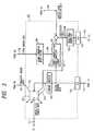
- Fig. 1is a block diagram showing one embodiment of a remote surgery supporting system of the present invention, which comprises realism control data generating means 101 for outputting virtual force reflection data 108, synthesized processed image 109 and virtual sound field, diseased tissue manipulating means 102, whose part is composed of a slave manipulator, for outputting slave manipulator position data 115, manipulation command generating means 103 for outputting manipulation command data 111 and synthesized force reflection 112, work environment data detecting means 104 for outputting force sensor data 105, proximity sensor data 106, visual sensor data 107 and magnification ratio data 116, in vivo data measuring means 117 for outputting an input signal for measuring the inside of organism and in measured data of the inside of the organism 121 and receiving an output signal 120 passed through or reflected from the inside of the organism, measurement data processing means 118 for outputting visualized in vivo data 122 reconstructed in 3-D or the like and action command inputting means 114 for outputting an
- the work environment data detecting means 104has sensor parts at the tip of and around the slave manipulator which is a component of the diseased tissue manipulating means 102 and detects the diseased part and the surrounding environment thereof as detection data 124 by a visual sensor, a force sensor and a proximity sensor at the end of the aforementioned manipulator.
- the realism control data generating means 101processes and synthesizes the data detected by the work environment data detecting means 104, the in vivo 3-D reconstructed image data outputted by the measurement data processing means 118 and the slave manipulator position data 115 to generate image, sound and virtual force reflection. Thereby, it shows the state of the patient to one or more surgical operators.
- the data of the force sensor and the proximity sensoris transmitted also to the manipulation command generating means 103.
- Actual force reflection detected by the force sensoris converted into a range which allows each surgical operator to sense.
- the virtual force reflection generated by the realism control data generating means 101is synthesized (combined) with the range-converted actual force reflection and manipulation force of other surgical operators and is transmitted to each surgical operator via the action command inputting means 114.
- Each surgical operatorinputs an action command to the diseased tissue manipulating means 102 via the action command inputting means 114 based on the data shown by the realism control data generating means 101.
- the action commandis translated into the manipulation command data 111 by the manipulation command generating means 103.
- the diseased tissue manipulating means 102interprets and executes the manipulation command data 111 with a parameter of the magnification ratio data 116 to manipulate (123) the diseased tissue.
- the in vivo data measuring means 117inputs the measuring input signal 119 to a diseased part 125 periodically and gets the output signal 120 passed therethrough or reflected therefrom. This signal is digitized and is sent to the measurement data processing means 118 as the measured data.
- the measurement data processing means 118operates the measured data obtained periodically and reconstructs the result as 3-D image data.
- Fig. 2shows one structural example of the realism control data generating means 101. It comprises a work environment data processor 201, a binocular view field controller 202, a display 203 for displaying processed image and virtual sound field reproducing means 210 and outputs the synthesized image data 211 synthesized with what virtual image data generated by the work environment data processor 201 and the visual sensor data 107, which is an actual image, are processed into and visualized, a control signal 213 of the binocular view field controller 202 and the virtual sound field 110 to the outside by a number of the surgical operators.
- the work environment data processor 201is equipped with a secondary data storage section 214 for recording data and is capable of recording time series data or the like of each sensor data of the visual, force and proximity sensors. This data is used in a simulation and training of surgery as described later.
- Fig. 14is a drawing showing the scene of Fig. 2 seen from the top. Hands of each surgical operator beyond the wrists appear as if they are tips 1401 of the slave manipulator.
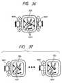
- Fig. 36shows an arrangement for a relatively small number of surgical operators.
- each own slave manipulatoris allocated to each surgical operator and each surgical operator can have a feeling as if each own hand is extending and continuing into the display.
- the surgical operatorscan refer the same image each other as if they are seeing an optically enlarged image of the diseased part (as if a lens is placed there) and can talk directly from each other.
- FIG. 15An example of an operation of the work environment data processor 201 will be explained below with reference to Figs. 15 through 24.
- a process for generating the virtual image datawill be explained first by using Figs. 15 through 18.
- a distance from a target position of the tip of the slave manipulatoris calculated based on the visual sensor data 107 and the proximity sensor data 106 in Step 1505 and the degree of the distance is represented by using one or a plurality of type of color (e.g., farther in red to nearer in violet), lightness of color (e.g., farther in higher lightness to nearer in lower lightness) and saturation of color (e.g., farther in higher saturation to nearer in lower saturation) in Step 1506.
- type of colore.g., farther in red to nearer in violet
- lightness of colore.g., farther in higher lightness to nearer in lower lightness
- saturation of colore.g., farther in higher saturation to nearer in lower saturation
- the proximity sensoris adapted to obtain the distance data by measuring an intensity of reflected wave of ultrasonic or light and a reflection time thereof for example.
- a distribution of stress at the diseased partis estimated based on the visual sensor data 107 and the proximity sensor data 106 in Step 1503 and the magnitude of the stress at each point of the image is represented by type of color (e.g., larger stress in red to small stress in violet), lightness of color (e.g., larger stress in high lightness to small stress in lower lightness) and saturation of color (e.g., larger stress in high saturation to small stress in lower saturation) in Step 1504.
- type of colore.g., larger stress in red to small stress in violet
- lightness of colore.g., larger stress in high lightness to small stress in lower lightness
- saturation of colore.g., larger stress in high saturation to small stress in lower saturation
- Step 1504 or Step 1506When the process in Step 1504 or Step 1506 ends, a virtual image composed of the color or the like representative of the distance or the stress is displayed by superimposing on the original image in Step 1507. That is, the spot where the distance between the diseased part and the slave manipulator is shorter or where more stress is applied is displayed more vividly or is colored with a specific color.
- the above-mentioned imagemay be displayed by superimposing on the in vivo data 122 reconstructed in 3-D or without superimposing it. In that case, it is possible to prepare different displays or to display them by opening different windows on the same display.
- Fig. 16shows a case when a motion of the tip of the slave manipulator is displayed in correspondence with the type, lightness and saturation of color.
- a positional deviation, velocity and acceleration of the slave manipulatorare calculated from the tip position data 115 thereof which contains reference values and responses in Step 1601.
- the values of the positional deviation, velocity and accelerationare represented by the type of color (e.g., larger value in red to smaller value in violet), the lightness of color (e.g., larger value in higher lightness to smaller value in lower lightness) and the saturation of color (e.g., larger value in higher saturation and smaller value in lower saturation) in Step 1602.
- the correspondence between the positional deviation, velocity and acceleration and the type, lightness and saturation of coloris arbitrary and a number of ways is conceivable.
- the representative colorsare displayed around the tip of the manipulator in the original image while being superimposed thereon in Step 1603. It may be displayed by superimposing on the in vivo data 122 reconstructed in 3-D or without superimposing it.
- Fig. 17shows a case when an image in an infrared wavelength range which has been converted into that in a visual light range is displayed.
- an infrared component at each point within the original imageis sampled from the visual sensor data 107 in Step 1701.
- the wavelength of the infrared component of each pointis shifted to a visual range while leaving the intensity of light of the component as it is in Step 1702.
- the imageis displayed by superimposing on the original image in Step 1703.
- the displaying method described aboveallows the diseased position to be readily specified by visualizing a distribution of temperature which is originally invisible because a temperature of ill part of the tissue is often different from that of the surrounding part in general.
- in vivo data reconstructed in imagesuch as image data given by MRI, X-ray CT and ultrasonic CT.
- Fig. 18shows one example thereof.
- a time derivative of position vector of the tip or a variation vector between sampled timesis calculated from the 115 in Step 1801.
- the magnitude and direction of the vectorare indicated by a translucent arrow in Step 1802 and the arrow is drawn starting from the tip of the manipulator in the original image in Step 1803.
- the virtual image data generated or synthesized by the process in Figs. 15 through 18 as described aboveis presented as a stereoscopic image to the operator (surgical operator) by driving the binocular view field controlling means 202 and the display 203 for displaying the synthesized image in synchronism.
- the in vivo data 122 reconstructed in 3-Dmay be also superimposed on the above-mentioned image.
- the imagemay be displayed by providing another display or by opening another window on the same display.
- Fig. 19it is detected and determined first whether the tip of the slave manipulator is in contact or not by the force sensor data 105 and the proximity sensor data 106 in Steps 1901 and 1902.
- the distanceis calculated based on the visual sensor data 107 and the proximity sensor data 106 in Step 1905 and the magnitude of the distance is represented by using one or a plurality of sound volume (e.g., farther in larger sound volume to nearer in smaller sound volume), timbre (time change of sound volume) (e.g., farther in larger change to nearer in smaller change), musical interval (height of sound) (e.g., farther in higher musical interval to nearer in lower musical interval) and tone color (distribution of components of fundamental wave and higher harmonic) (e.g., farther in fewer components to nearer in more components) in Step 1906.
- sound volumee.g., farther in larger sound volume to nearer in smaller sound volume
- timbretime change of sound volume
- musical intervale.g., farther in higher musical interval to nearer in lower musical interval
- tone colordistributed of components of fundamental wave and higher harmonic
- a distribution of stress at the diseased partis estimated based on the visual sensor data 107 and the proximity sensor data 106 in Step 1903 and the magnitude of the stress at one point of the tissue closest from the tip of the manipulator is represented by using one or a plurality of the sound volume (e.g., larger stress in larger sound volume to smaller stress in smaller sound volume), timbre (time change of sound volume) (e.g., larger stress in larger change to smaller stress in smaller change), musical interval (height of sound) (e.g., larger stress in higher musical interval to smaller stress in lower musical interval) and tone color (distribution of components of fundamental wave and higher harmonic) (e.g., larger stress in fewer components to smaller stress in more components) in Step 1904.
- the sound volumee.g., larger stress in larger sound volume to smaller stress in smaller sound volume
- timbretime change of sound volume
- musical intervalheight of sound
- tone colordistributed of components of fundamental wave and higher harmonic
- Step 1904 or 1906ends, the above-mentioned sound data is reproduced by means of the virtual sound field reproducing means 210 in Step 1907. That is, the sound volume becomes larger, the musical interval becomes higher, the timbre becomes brighter or the sound type becomes metallic at the spot where the distance between the diseased part and the slave manipulator is shorter or where a more stress is applied.
- the virtual sound fieldrepresents the distribution of stress or the distance, it can be done easily by changing the musical interval or by interrupting the sound for example.
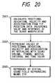
- Fig. 20shows a process when the motion of the tip of the slave manipulator is represented in correspondence with the sound volume, timbre, musical interval and tone color.
- a positional deviation, velocity and acceleration of the slave manipulatoris calculated from the tip position data 115 thereof which contains reference values and responses in Step 2001.
- the values of the positional deviation, velocity and accelerationare represented by the sound volume (e.g., larger value in larger volume to smaller value in smaller volume), the timbre (time change of sound volume) (e.g., larger value in larger change to smaller value in smaller change), musical interval (height of sound) (e.g., larger value in higher musical interval to smaller value in lower musical interval) and tone color (distribution of components of fundamental wave and higher harmonic) (e.g., larger value in fewer components to smaller value in more components) in Step 2002.
- the correspondence between the positional deviation, velocity and acceleration and the sound volume, timbre, musical interval and tone coloris arbitrary and a number of ways is conceivable.
- Fig. 21shows a process for making a distribution of temperature obtained from an image in an infrared wavelength range to correspond with changes of sound.
- an infrared component at each point within the original imageis sampled from the visual sensor data 107 in Step 2101.
- an intensity of light at the point closest to the slave manipulatoris interpreted as a temperature and is made to correspond with any one of the sound volume, timbre, musical interval or tone color in Step 2102.
- the virtual sound filed reproducing means 210is reproduced by the virtual sound filed reproducing means 210 in Step 2103.
- Fig. 22shows one example thereof.
- a time derivative of position vector of the tip or a variation vector between sampled timesis calculated from the 115 in Step 2201. Then, the magnitude and direction of the vector are represented by sound volume, timbre, musical interval, tone color and image orientation of wind-cutting sound in Step 2202 and is reproduced by the virtual sound field reproducing means 2101 in Step 2203.
- the virtual sound field generated by the work environment data processor 201 as described aboveis presented to the operator by the virtual sound field reproducing means 210. Thereby, the use of the sound field allows the realism to be added further and each surgical operator to operate more readily.
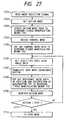
- Fig. 23shows one example thereof. At first, it is detected and determined whether the tip of the slave manipulator is in contact or not from the force sensor data 105 and 106 in Steps 2301 and 2302. No action is taken in Step 2303 when the slave manipulator is not in contact.
- the virtual force reflection data 108is transmitted to the manipulation command generating means 103 in Step 2306.
- a potentialis set which will create a large virtual repulsive force when the distance between the diseased part and the slave manipulator is short.
- a distribution of intensity of light of an infrared rangeis sampled from the visual sensor data 107 in Step 2401.
- virtual force reflection Fvwhich corresponds to the intensity of light at each point of image and whose depth direction is opposite is calculated in Step 2402. It is then transmitted to the manipulation command generating means 103. Thereby, it allows a contactless palpation of sensing a degree of temperature by a magnitude of the force reflection.
- a method for calculating the virtual force reflection Fvis the same with that described before. However, it becomes impossible to distinguish which value is indicated if the generated virtual force reflection and the virtual force reflection obtained by the process in Fig. 23 are generated and output in the same time. Accordingly, it is preferable to set which value is indicated in advance by switching modes for example.
- an operation which can be called as a so-called contactless palpationmay be performed by taking out the in vivo data reconstructed in image such as the brightness at the tip of the manipulator of the image data given by MRI, X-ray CT and ultrasonic CT, instead of the intensity of light in the infrared wavelength range, and by converting it into force reflection by the method described above. It is very effective from the aspects of the specification of the diseased position and of the readiness of operation.
- the work environment data processor 201superimposes and processes the force sensor data 105, the proximity sensor data 106, the visual sensor data 107, the 115 and the visualized in vivo data 122 reconstructed in 3-D and based on them, converts the quality of the data or generates new data.
- Fig. 3is a block diagram showing a structure of the manipulation command generating means 103 which comprises a virtual switch 307 for controlling a transfer of an action command, a force sensor data operating section 308 for amplifying the force sensor data 105 so as to convert into an adequate range and for performing a recursive calculation which corresponds to removal of noise to output actual force reflection data 309, a command converter 310 for setting an action mode/control mode from the action command data 113 and for taking in each joint data from the action command inputting means 114, an A/D converter 318, a D/A converter 319, an other's manipulation force computing element 320 for giving a value obtained by adding and converting a weighted quantity of manipulation (e.g., manipulation force) of each surgical operator other than oneself to that surgical operator as force reflection and a force/torque transducer 322.
- Arrows in the figureindicate flows of signal or data.
- the force sensor data operating section 308converts the magnitude of the force sensor data 105 into an adequate level for human muscle force in Step 2501 and performs a recursive calculation equivalent to a low-pass filter to remove noise in Step 2502.
- Step 2503After weighting each degree of freedom in Step 2503, it adds an output 321 of the other's manipulation force computing element 320 and the value of the virtual force reflection data 108 to generate synthesized force reflection data in Step 2504 and inputs it to the force/torque transducer in Step 2505.
- the force/torque transducer 322converts the synthesized force reflection data into each joint torque value of a force reflection generating section of the action command inputting means 114 in Step 2601 and outputs it as analog data through the D/A converter 319 as shown in Fig. 26.
- the outputis transmitted to the action command inputting means 114 and becomes a torque command of a driver of each joint actuator in Step 2603.
- the above-mentioned processis performed by a number of the action command inputting means 114, i.e., a number of channels.
- An operation of the other's manipulation force computing element 320will be explained later in detail.
- the command converter 310reads a mode selection signal which is contained in the signal from the action command inputting means 114 in Step 2701. It sets an action mode in Step 2702 and outputs the action mode to the diseased tissue manipulating means 102 in Step 2703.
- Step 2704decides a control mode based on the action mode in Step 2704 and puts out the control mode to the diseased tissue manipulating means 102 in Step 2705.
- Some control modeis not permitted depending on the action mode, so that the control mode is decided in Step 2704 by automatically selecting from ones other than such unpermissible control mode in accordance to an adequately set algorithm or is decided by inputting from the action command inputting means 114.
- Step 2706After deciding the control mode and outputting it to the diseased tissue manipulating means 102, it gets each joint angle data through the AID converter 319 in Step 2706 and translates it into a work coordinate system in Step 2707.
- Step 2708After putting out manipulator tip position reference value data to the diseased tissue manipulating means 102 in Step 2708, it monitors the action mode in Step 2709 and if the action mode is "Stop", it advances to a stop mode and if it is not, returns to Step 2706 in Steps 2710 and 2711.
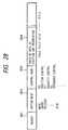
- a train of data transmitted to the diseased tissue manipulating means 102comprises a header 2801, an action mode 2802, a control mode 2803 and a train of data of position and orientation 2804 until an arbitrary time tn. It is transmitted to the diseased tissue manipulating means 102 sequentially.
- Step 2901a distance between the position of the tip of the manipulator and the diseased part is detected in Step 2901 and is checked whether it is less than a certain value or not in Step 2902. If it is not less than the certain value, the process returns to Step 2901.
- the position and velocity of the tip of the manipulator in the neighborhood of the diseased partare detected by the proximity sensor in Step 2903.
- Step 2901the magnitude of the velocity vector and the magnitude of each component thereof, the magnitude of the virtual force reflection and the magnitude of each component thereof and the magnitude of a velocity command vector and the magnitude of each component thereof when the control mode is velocity- servo are checked and if they are all less than the certain value, the process returns to Step 2901 and if any one of the conditions is not met, the control mode is turned to position control and the current position is set as a command value in Steps 2904 through 2910.
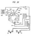
- the action command inputting means 114will be explained below with reference to Fig. 30. Even if a plurality of the action command inputting means 114 are used, the structure thereof is the same. It comprises a magnet 3001 for coupling grip and force reflection generating section, a grip constraining solenoid controlling signal 3002 and a coupling electromagnet current controlling signal 3003, a grip constraining solenoid 3004, an action mode switching switch 3006, a grip 3007, a globular coupler 3008, spherical joints 3009 and direct acting cylindrical electrostatic actuators 3010.
- the synthesized force reflection 112 decomposed per each actuator and output from the manipulation command generating means 103is applied to each actuator as control input 3011.
- Each actuator 3010is driven by it and generates a required force reflection as a whole. Displacement of each actuator 3010 is detected by a displacement sensor not shown and is output as a displacement sensor output 3012.
- Each surgical operatorholds the grip 3007 and moves it while sensing force reflection to input action data.
- the modeis switched by manipulating the action mode switching switch 3006 on the grip to output an action mode setting signal 3005.
- the globular coupling 3008 between the grip 3007 and the force reflection generating sectionis coupled by magnetic force of the electromagnet.
- the coupler 3008is constructed so as to be controlled by the grip constraining solenoid controlling signal 3002 and the coupling electromagnet current controlling signal 3003 from the magnetic force controlling means 3001 in accordance to the action mode and the magnitude of input and to be able to change a constraint in terms of a degree of freedom.
- Fig. 35is a flow chart showing the operation of the magnetic force controlling means 3001, wherein it reads the action mode switch in Step 3501 and when the action mode is a mode which instructs only position in Step 3502, it exerts only the magnetic force of the electromagnet in Step 3503.
- the coupler 3008is globular as shown in Fig. 30, it is free in terms of its orientation. In other words, only three degrees of freedom of position can be instructed by manipulating the grip 3007.
- change in the orientationcan be instructed by clipping the bottom of the grip by the solenoids 3004 when all six degrees of freedom of position and orientation are to be instructed, as indicated in Step 3504 in Fig. 35.
- the grip 3007may be those as shown in Fig. 38, beside the pen-type grip shown in Fig. 37.
- Fig. 38ashows a pincette-type grip
- Fig. 38ba ligator-type grip
- Fig. 38ca clamp-type grip. The operator can manipulate any one of them while sensing force reflection generated by the grip force reflection generating actuator 38001.
- one side or both sides of part of the grip for hooking fingersrotate centering on an axis of rotation 3802.
- the operatorcan replace the grip 3007 by releasing both the clipping and magnetic force caused by the solenoids 3004 at this time. That is, the operator can attach/remove the grip corresponding to the circumstance to use to input action commands.
- an initial signal corresponding to the shape of the gripis transmitted to the diseased tissue manipulating means 102 via the manipulation command generating means 103 and a manipulator having a tool corresponding to that as an effector is assigned. Accordingly, it is just necessary to provide several kinds of tools for this part and it is not necessary to prepare the action command inputting means by a number of tools in advance.
- Fref kW 1 f 1 + W 2 f 2 + ... + W k-1 f k-1 + W k+1 f k+1 + ... + W n f n
- Fextis the force sensor data 105 and is a vector quantity.
- Fref k and Fext kare added and output in Step 3905. It is synthesized with the virtual force reflection data 108.
- the algorithm described aboveallows the operators who input action from different input means to perform works while sensing the force generated by the others and the force reflection from the object.
- the work environment data detecting means 104will be explained below with reference to Fig. 4.
- the work environment data detecting means 104comprises visual sensors 402, a visual sensor mounting section 403, a passive rotary joint 404 for linking the both of them, a linear actuator 405 for adjusting angle of parallax, an illumination 410 for illuminating the diseased part, a force sensor and force sensor signal pre-processing circuit 412 a proximity sensor and proximity sensor signal pre-processing circuit 413 attached at the tip portion of the slave manipulator.
- the visual sensors 402take in an image of the diseased part and outputs the image signals for right-eye and left-eye 406 and 407.
- the visual sensors 402are linked to the mounting section 403 via the passive rotary joint 404.
- the image signals 406 and 407are digitized and turned into the visual sensor data 107 in the operation controlling means 401.
- the force sensor signal 414 and the proximity sensor signal 416are also converted into digital values to turn to the force sensor data 105 and the proximity sensor data 106.
- the operation controlling means 401controls each part by an algorithm as shown below.
- Fig. 32when it detects a quantity of move of a coarse motion part 503 (see Fig. 5, described later) of the diseased tissue manipulating means 102 in the depth direction of the diseased part in Step 3201, it sends the control signal 408 to the linear actuator 405 so that the angle of parallax of the right and left visual sensors becomes equal to a value at the reference position in Step 3202. Then, the angle of parallax can be maintained constant as the linear actuator 405 expands/contracts and the right and left visual sensors 402 rotate finely and equally centering on the passive rotary joint 404.
- the force sensor and the pre-processing circuit 412 thereof and the proximity sensor and the pre-processing circuit 413 thereofare mounted at the tip 411 portion of the slave manipulator.
- the small force and proximity sensors and the signal processing circuits thereofmay be manufactured by micro-machining technology. While the force sensor outputs the force sensor signal 414 and the proximity sensor outputs the proximity sensor signal 416, respectively, the operation controlling means 401 sends the control signals 415 and 417 to each processing circuit corresponding to a signal level to change the amplification factor at that time.
- a digital signal of several bits having a higher voltage as compared to a noise level assumed to be brought about thereis used for the control signal and a control process as shown in Fig. 31 is carried out.
- the operation controlling means 401instructs the pre-processing circuit to multiply the amplification factor by c times in Step 3104.
- the processing time between the Steps 3101 and 3103is very short and it is assumed that the value of the signal will not change during that time.
- the above-mentioned amplifier outputis again sampled and zero-order-held in Step 3105 and is converted from analog to digital in Step 3106. Then, the digitized value is expressed by real number and is divided by c in Step 3107. That is, when the signal level is small, the amplification factor of the pre-processing circuit is increased to prevent the signal from being buried by the noise which is mixed in until it is input to the operation controlling means 401 and when the signal level is large, the amplification factor is reduced to prevent the signal from saturating. Thereby, it becomes possible to reduce the effect of the noise from the surrounding environment and the actuator and to reduce the effect of quantization due to the digital sampling.
- the diseased tissue manipulating means 102will now be explained.
- Fig. 5it comprises manipulation command interpreting and controlling means 502, the coarse motion part 503, the fine motion part 504 and the superfine motion part 508 as a whole.
- Each partis manufactured by using only a material which receives almost no force from a magnetic field as compared to a structural material often used, such as polymeric materials like plastics.
- the diseased tissuemay be manipulated without being influenced by the magnetic field even when MRI is used as one of structural element of the in vivo data measuring means 117 described later. Or, conversely, because in vivo data created by the MRI can be obtained during operation, i.e., during when the diseased tissue is manipulated, it becomes possible to pursue any deformation in the tissue surrounding the diseased part in real-time and to perform operations while measuring functions in addition to shape especially in craniotomy for example.
- the superfine motion part 508has a plurality of manipulators and various treatment effectors may be attached to the tip thereof.
- the manipulation command 111comprises a command whose degree of abstraction is high such as "grasp", a control mode and a train of time-series motion command data of the tip of one manipulator.
- the manipulation command interpreting and controlling means 502interprets it and generates motion commands of each joint of the 505 and the manipulator (a plurality of manipulators if necessary) of the superfine motion part 508 and makes a servo-level primitive control in the same time from the grasp command, the control mode and the motion command value of one manipulator.
- Control input 506 to each joint of the 505 and control input 509 to each joint of the superfine motion part 508 and the end effectorare determined by using the above-mentioned manipulation command, displacement sensor data at each part 504, 507 and 510 and the force sensor data 105.
- Fig. 34shows an operation flow of the manipulation command interpreting and controlling means 502.
- Step 3403it reads the control mode and the action mode from data transmitted in the sequence as shown in Fig. 28 from the manipulation command generating means 103 in Steps 3401 and 3402 and interprets train of position and orientation data based on the control mode in Step 3403.
- the control modespecifies a control scheme such as position control/velocity control/impedance control, an instructed number of degree of freedom and existence of anisotropy related to the degree of freedom.
- the controlling means 502makes joint servo control of the specific manipulator based on the command value in Step-3405.
- the processis ramified here in accordance to the action mode in Step 3406 and if the mode is MOVE, the process is finished.
- a virtual attracting force potentialwhich acts between tips of the specific manipulator (the manipulator to be manipulated by the train of position and orientation data) and the other manipulator is set in Step 3407 and a balanced point of the potential (point where the attracting force becomes zero) is set within a space created by the tip of each manipulator in Step 3408.
- the other manipulatordecomposes the force which virtually acts on the tip to torque of each joint to control the torque in Step 3409.
- the coarse motion part 503will now be explained with reference to Fig. 6.
- the coarse motion part 503comprises a pedestal 601, a first link 602, a first joint 603, a second link 604, a second joint 605, a third link 606 and a third joint 607 and a 608 is provided at the third joint 607.
- the pedestal 601is coupled with the first link 602 with a linear motion rail and the mechanism of the first link and thereafter may be moved horizontally along the transverse direction of the pedestal 601.
- a degree of freedom of this partis manually set and a mechanical lock is provided so as to be able to secure at any position.
- first link 602is semi-circular, it is not always necessarily to be semi-circular so long as it does not interfere with the mechanism of the second link and thereafter.
- the second link 604is coupled with the first link 602 via the first joint 603 and rotates axially on the center line of the first joint 603 on the both sides.
- the first joint 603is also constructed so as to be manually rotated and to be locked by the same reason with the case of the manual linear motion rail.
- the shape of the second link 604is semi-circular.
- the third link 606is coupled with the second link 604 via the second joint 605 and rotates axially on the center line of the second joint 605.
- the third link 606is also constructed so as to be manually rotated and to be mechanically locked to enhance the safety.
- the shape of the third link 606is also semi-circular.
- the fine motion part 608is coupled with the third link 606 via the third joint 607.
- the third joint 607moves directly in the normal direction of the third link 606.
- Displacement sensor data 504 of each jointis sent to the manipulation command interpreting and controlling means 502 which has been described with reference to Fig. 5.
- this coarse motion part systemcan have the mechanism and structure of degree of freedom of one degree of freedom of the parallel move and three degrees of freedom of the spherical coordinate system which accommodate with a shape of cranial bone of a lying patient and allows coarse positioning of the patient in the beginning of an operation and removal thereof in case of emergency for example to be swiftly and readily made.
- the 505comprises a pedestal link 704, a first joint 705, a second link 706, a second joint 707, a third link 708, a third joint 709 and a base 712 of the fine motion part.
- the first through third jointsare all rotary joints and it is constructed so that only an orientation of the whole superfine motion part is changed.
- the change in orientationis independent of scaling. That is, while a small value becomes an object of the work with respect to a distance, the fine work is the same with the normal work with respect to the change in orientation. Accordingly, the degree of freedom of the position and orientation can be separated and the same driving method and mechanism with those in the normal scale can be used in terms of the orientation.
- the change in orientation of the superfine motion part 508is linked with the visual sensor 402. Thereby, a focus point of the visual sensor 402 is always positioned approximately in the work space of the manipulator of the superfine motion part 508.
- the 505has had a gimbal structure in Fig. 7, a mechanism such as Stewart platform may be used.
- the superfine motion part 508will be explained below with reference to Fig. 8.
- the superfine motion part 508comprises columns 801, a ring rail 802, a first joint 803, a first link 804, a second joint 805, a second link (tip of slave manipulator) 411 and a Peltier effect element 809.
- the first joint 803moves in two degree of freedom of linear motion in the direction of center line of the ring rail 802 and of rotation around the center line.
- the second joint 805is cylindrical and rotates around its center line.
- the structure described aboveallows the whole manipulator to be compact. While the superfine motion part 508 is constructed to have three degrees of freedom, it is possible to increase the degree of freedom by replacing the structures of the first link 804 and the second link 411 so as to have the same structure with the first joint 803. In the present embodiment, more than six degrees of freedom has been realized by adding the degrees of freedom of the superfine motion part 508 with the three degrees of freedom of rotation of the fine motion part.
- the Peltier effect element 809 which is attached at the tip of the manipulatoris an element for realizing thermoelectric refrigeration by the Peltier effect which can be realized by micro-machining technology.
- the manipulator itselfis provided with mechanical force which can destroy organic tissues such as brain tissue, nerve and blood vessel, it becomes very dangerous when it causes an accident such as a runaway. Then, it is necessary to replace cutting and peeling of diseased tissues which has been done by mechanical force in the past with the manipulation which causes tissues to degenerate by controlling a flow of energy in the fine surgery.
- the reduction of the required mechanical forcebrings about merits in design that the manipulator and the actuator which drives the manipulator can be miniaturized further or specifications required for them may be eased and is very favorable.
- the superfine motion part which is less invasive and causes less effect around itmay be realized as described above.
- the manipulatormay be equipped with a laser knife, an ultrasonic knife or an electric knife or a small clamp, knife or clip may be attached to it.
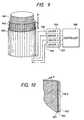
- Fig. 9shows what the first joint 803 in Fig. 8 is taken out.
- the first joint 803comprises an inner stator 901, i.e., a small portion of the ring rail 802, a multi-degree of freedom mover 902, an outer stator 903 to which the first link 804 is coupled hardly, a driving circuit 904 for controlling an electrode voltage of the outer stator 903, driving circuits 905 and 907 for controlling electrode voltages of the peripheral surface and of the inner peripheral surface of the multi-degree of freedom mover 902, a driving circuit 906 for controlling an electrode voltage of the inner stator 901 and a main controller 908.
- Materials of the mover and statorare polyimide and adhesive.
- a conductive polymer compound mainly composed of carbon moleculesis used as the electrode.
- Ring-shaped electrodesare disposed on the periphery of the inner stator 901 vertically to the axis of the cylinder. Electrodes are also disposed on the inner periphery of the multi-degree of freedom mover 902 in parallel with the inner stator 901 and a large number of linear electrodes are disposed on the periphery thereof vertically to the inner stator 901. Although not shown, flanges are attached on the both sides of the multi-degree of freedom mover 902 to constrain the degree of freedom of the outer stator 903 only to rotation around the center line of the cylinder. A large number of linear electrodes are disposed on the inner periphery of the outer stator 903 in parallel with the electrodes on the periphery of the multi-degree of freedom mover 902.
- Fig. 10is a section view of the first joint 803 shown in Fig. 9 cut along a plane including the center axis and a plane orthogonal to that.
- Fig. 11is an enlarge view of the section at part A in Fig. 10 and
- Fig. 12is an enlarged view of the section at part B.
- the outer stator 903is covered with an inner cover 1110 and an outer cover film 1113 on the both sides thereof and an adhesive 1112 is filled between th both films.
- Carbon polymer compound electrodes 1111are disposed at equal intervals so that it becomes a line of intersection of the cylinder and the plane including the center axis of the cylinder. Its section is like a chain line as shown in Fig. 12.
- the structure of the peripheral portion of the multi-degree of freedom mover 902is the same with that of the outer stator 903 and the structure of the inner peripheral portion thereof with that of the inner stator 901. Insulating fluids 1108 and 1109 are filled between the inner stator 901 and the multi-degree of freedom mover 902 and between the multi-degree of freedom mover 902 and the outer stator 903, respectively.
- Fig. 12is the sectional enlarged view of part B in Fig. 10 and the same members are denoted with the same reference numerals.
- the direction of the electrodesis opposite from that in Fig. 11 because the direction of section is orthogonal to that in Fig. 11.
- Fig. 13is a section view showing a combination of the outer stator 903 and the peripheral portion of the multi-degree of freedom mover 902.
- Three-phase alternating voltagesare applied to the electrode 1111 of the outer stator 903 and a peripheral electrode 1303 of the multi-degree of freedom mover 902, in a set of three electrodes, via wires 1301 and 1304.
- the voltages applied to the electrodes 1111 and 1303are antiphase or when their frequency is different, a driving force is generated between the mover and the stator, translating the mover 902 in the direction of axis of the cylinder.
- the set of the electrodes at the inner portionis orthogonal to the set of the electrodes at the outer portion, the set of the inner electrodes generates, microscopically, a driving force in the tangential direction of a circular section vertical to the axis of the cylinder. Integrating this driving force in the circumferential direction turns it to a turning force around the axis and the multi-degree of freedom mover 902 rotates.
- the above-mentioned motions in the two directionsare orthogonal from each other and one motion generated by one combination will not change the positional relationship of the electrodes in another combination. Accordingly, the first joint 803 can translate in the axial direction of the cylinder and rotate around the axis in the same time.
- the in vivo data measuring means 117will be explained below with reference to Fig. 40.
- the in vivo data measuring means 117comprises a measurement signal transmitting section 4001 and a measurement signal receiving section 4002.
- the measurement signal transmitting section 4001is equipped with an X-ray tube, a superconductive magnet and magnetic coils, ultrasonic transducer and the like to be able to transmit measurement signals in various modalities such as X-ray, magnetic field and ultrasonic.
- the measurement signal receiving section 4002is equipped with receiving equipments which correspond to each modality to receive an input signal 119 which penetrates through or is reflected by the body of the patient and comes out as an output signal 120.
- X-ray transmitted from the X-ray tube and penetrated through the bodyis received by an arrayed two-dimensional X-ray sensors.
- Signals which originate 3-D CT imagemay be obtained in a very short time by turning those transmitting and receiving sections around the patient. This is a system called a cone-beam CT.
- a fluctuating magnetic field generated by the magnetic coilis caught by a RF (Radio Frequency) probe. It adopts the same principle with a measuring instrument called MRI.
- MRIMagnetic resonance Imaging
- a transmitting section and a receiving section of the ultrasonic transduceris arranged and disposed in a shape of two-dimensional array.
- the X-ray CTprovides signals which originate the data of shape of the neighborhood of the patient including the bone and the MRI provides signals which originate data of shape, visualized data of difference of tissues which is undistinguishable by naked eyes and visualized data of brain function.
- the ultrasonicprovides signals which originate data of shape and data which indicate local abnormal blood stream and dyskinesia.
- the measurement by means of the multiplex modalities described aboveis carried out with a very short period regardless whether before or during operation and obtained signal data is digitized and pre-processed in the signal receiving section 4002.
- the digitized measurement data 121is sent to the measurement data processing means 118.
- the measurement data processing means 118comprises an image processing and operating section 4101, a main storage 4102, a secondary data storage 4103 and an address and data bus 1104.
- the main storage 4102is a normal memory and the secondary data storage 4103 is a mass storage like an optical magnetic disk. These devices 4101 through 4103 are linked closely by the address and data bus 4101 to allow a super-high speed image processing and operation.
- the measured data 121is stored in the main storage 4102 passing through the image processing and operating section 4101. It is processed and is reconstructed as three-dimensional image data by the image processing and operating section 4101.
- the reconstructed data 122is sent to the realism control data generating means 101 to be synthesized with the other images.
- the in vivo datais reconstructed in 3-D and visualized regardless whether before or during operation and is presented to the surgical operator while being updated with a short period.
- the 3-D image data reconstructed at this timeis stored in the secondary data storage 4103. This data is used in carrying out simulations and training, beside during the surgical operation.
- a virtual diseased partis produced by the realism control data generating means 101.
- Actual diseased part image datagenerated by reconstructing in 3-D from the measured data and stored in the secondary data storage 214 in Fig. 2 or the second storage 4103 in Fig. 41 is used or virtual diseased part image data is generated from some model. It is then displayed and virtual force reflection data 108 is generated and is sent to the manipulation command generating means 103. Because there is no force reflection from the actual world at this time, the virtual force reflection is equal to synthesized force reflection.
- the virtual force reflectionis calculated based on a dynamic model stored in the secondary data storage 214 within the work environment data processor 201.
- the calculation resultis sent to the action command inputting means of each surgical operator to transfer the virtual force reflection.
- the surgical operatorsmanipulate the slave manipulators in the real world within the virtual environment.
- the manipulatormoves following the intention of the surgical operator and detects each sensor data. Among them, only the visual sensor is sent to the realism control data generating means 101 to combine with the virtual diseased part image data.
- the simulationmay be carried out by one person or the "bodily" training may be carried out by using the multi-to-one master/slave function described before.
- the secondary data storage 214 within the work environment data processor 201records also each data time series of this simulation of surgery. Accordingly, the recorded result may be reproduced in another occasion to evaluate actions and decisions.
- a case when the explanation is made by using actual, not virtual, operation record datais done as follows.
- the data in the secondary data storage 214 within the work environment data processor 201 and the data in the secondary data storage 4103 in the measurement data processing means 118contain data for synchronization. Those data is combined and reproduced on the display 203 of the realism control data generating means 101 based on that data. It is possible to reproduce only the actual image or to reproduce only the measured data reconstructed into 3-D image.
- the surgical operatorcan explain the operation to the patient having the similar symptom by reproducing the image.
Landscapes
- Health & Medical Sciences (AREA)
- Surgery (AREA)
- Engineering & Computer Science (AREA)
- Life Sciences & Earth Sciences (AREA)
- Medical Informatics (AREA)
- General Health & Medical Sciences (AREA)
- Biomedical Technology (AREA)
- Heart & Thoracic Surgery (AREA)
- Nuclear Medicine, Radiotherapy & Molecular Imaging (AREA)
- Molecular Biology (AREA)
- Animal Behavior & Ethology (AREA)
- Robotics (AREA)
- Public Health (AREA)
- Veterinary Medicine (AREA)
- Manipulator (AREA)
- Magnetic Resonance Imaging Apparatus (AREA)
- Surgical Instruments (AREA)
- Ultra Sonic Daignosis Equipment (AREA)
- User Interface Of Digital Computer (AREA)
Description
- The invention relates to a remote surgerysupporting system, and more particularlyto a remote surgery supporting systemsuitable for supporting one or more surgical operators in givinga surgical treatment of brain, nerve system, eyeballs or thelike by remote-controlling surgical tools or therapeuticinstruments by a manipulator having a high degree of freedom.
- Hitherto, as a system for performing an operation forcranial nerve or the like while seeing data of measuringinstruments visually reconstructed, there has been known amagnetic resonance monitoring treatment system by which aposition of catheter is automatically controlled by apositioning mechanism when a surgical operator instructs aposition and insertion of the catheter while seeing an imageof the MRI as disclosed in the JP-A-4-53533for example.
- Further, as a system for cerebral surgical works, therehas been a puncturing manipulator for stereotaxy as disclosedin Japanese Patent Laid-open No. Hei. 3-121064 for example. Asa system for performing a surgery by way of remote control, therehas been a system having a remote-controlled surgicalmanipulator in a double-piped probe as disclosed inthe JP-A-4-146097 for example.
- Further, there has been known a micro-handling systemconstructed so as to allocate degrees of freedom to turning andtranslation to a manipulator and a stage as disclosed in acollection of papers pp. 693 - 696 of the Symposium on RoboticsMechatoronics in 1993, The Japan Society of MechanicalEngineers.
- The system described in the JP-A-4-53533is supposed to be used in a treatment mainly bymeans of a catheter and it is difficult to perform with it anoperation which requires a direct manipulation of diseased partwith a highly sophisticated technical skill such as a removalof tumor adhering on a blood capillary or nerve.
- Furthermore, because an ultrasonic motor (piezoelectricelement) is used for an actuator to operate in a static magneticfield, it is difficult to increase a compliance to enable worksof treating soft tissues.
- It is also incomplete more or less in terms of the modefor supporting data because the modality thereof is onlymagnetic resonance such that it is hard to understand changesin a shape of a cranial bone when craniotomy is performed, themeasured contents only show shapes and no functionalmeasurement is implemented and the measured and displayedcontents show a 2-dimensional tomographic image which is notintuitional.
- The system described in the above-mentionedJP-A-3-121064 is used for stereotaxy and is capable of performing only puncturing. However, there are manytroubles of cranial nerve which cannot be surgically treatedwell only by puncturing and which require a plurality ofmechanisms having a more degree of freedom in order to manipulatetissues of diseased part. The above-mentioned system is unableto deal with such case. Further, the disclosure describesnothing about other parts for controlling the puncturingmanipulator.
- The system disclosed in the above-mentionedJP-A-4-146097 isolates the surgical operatorcompletely from the patient, so that it will have a difficultyin responding to an emergency and even if it could, it may belate considerably.
- The system described in the collection of papers of theSymposium on Robotics Mechatoronics in 1993, The Japan Societyof Mechanical Engineers, is constructed so that the work cannotbe started unless an object is placed on the stage and is notsuitable for actual surgical works.
- Further, in all the examples described above, the mastermanipulator and the slave manipulator correspond in a relationof one-to-one to the end and no consideration is given to theenhancement of works and simplification of control attained bycontrolling a plurality of slave manipulators by one mastermanipulator and to the training function attained bycontrolling one slave manipulator by a plurality of mastermanipulators.
- Still more, all the known examples described abovesuppose tacitly that one surgical operator manipulates thesystem and describe nothing about a joint surgical work functiongiven by a plurality of surgical operators, the manipulationof one slave manipulator by a number of master manipulators,and the training function thereof.
- In the known examples described above, the data has beenobtained only for the sake of the surgical operator to the endregardless whether before or during the operator.
- Furthermore, they had no function of giving a surgicalsimulation and could offer no profit from the result regardlesswhether the object of the surgery is an actual dummy vital tissueor a model in a computer.
- WO93/13916 describes a tele-operator system with telepresencewhich can be used for surgical procedures includingright- and left-hand controllers for control of a right and aleft manipulator through the use of a servo mechanismincluding a computer. Video cameras view a workspace fromdifferent angles for the production of stereoscopic signaloutputs at lines. In response to the camera outputs a 3-Dimage is produced and reflected towards the eyes of theoperator. A virtual image is produced adjacent the controlarms which is viewed by the operator looking in the directionof the control arms. By locating the work space imageadjacent the control arms the operator is provided with asense that end effectors carried by manipulator arms andcontrol arms are substantially integral and that he isdirectly controlling the end effectors by hand.
- Several concepts for a robot work station for computer-assistedsurgery are described by P. Dario, S. Matelli and A.M. Sabatini in the article "An experimental set-up forinvestigating sensor-based tele-operated surgery procedures"published in: Proceedings of the twelfth annual internationalconference of the IEEE Engineering in Medicine and BiologySociety, Volume 12, 1990, page 1942.
- In Surgical Enthroscopy 7 (1993), No. 3, pages 203 to 205, apaper by R. M. Satawa titled "Virtual Reality SurgicalSimulator" has been published giving an overview on thedevelopment of virtual reality surgical simulators as anexample for the use of computer simulation for surgery.
- It is an object of the invention toprovide a remote surgery supporting systemfor supporting one or more surgical operators in giving asurgical treatment of brain, nerve system, eyeballs or the likeby remote-controlling surgical tools or therapeuticinstruments by a manipulator having a high degree of freedomwhile seeing data of various measuring instruments visuallyreconstructed.
- It is another object of the invention to providea master-slave type remote surgery supporting systemwhich allows to perform surgical works which require a large degree of freedom and a plurality of cooperationat the terminal within a narrow space.
- It is still another object of the invention toprovide a multi-master and multi-slave type remote surgerysupporting system which allows a pluralityof surgical operators to perform surgical works in cooperation.
- It is s further object of the invention to providea remote surgery supporting system whichcompensates a drop of working skill of a surgical operator causedby a drop of eyesight and degradation of terminal resolutionfrom aging.
- It is another object of the invention to providea remote surgery supporting system whichprevents blood infection between a patient and a surgicaloperator.
- It is another object of the invention to providea remote surgery supporting system whichrealizes surgery having less invasion by utilizing mainly adegeneration of tissues.
- It is another object of the invention to providea remote surgery supporting system which allows the surgicaloperators to transfer their working skill among them.
- It is another object of the invention to providea remote surgery supporting system which allows to performconsistently from a surgery training to a surgery simulation,to informed consent for a patient utilizing results thereof, and to a surgical operation. These objects are accomplishedby a remote surgery supporting system having thefeatures of claim 1.
- A mechanism for positioning the surgical tools ortherapeutic instruments of the diseased tissue manipulatingmeans of the present invention is made of a material and isconstructed by a drive theory less sensitive to the magneticfield.
- Further, the realism control data generated by therealism control data generating means of the present inventioncontains at least one of: a virtual image to be presented tothe surgical operator by synthesizing with the image data takenin by the working environment data detecting means and themeasured data image generated by the measurement dataprocessing means; a virtual sound field to be presented to thesurgical operator as sound data; and virtual force reflectiondata to be presented to the surgical operator by combining withthe contact force in the manipulation command generating means.
- The manipulation command generating means of the presentinvention transmits synthesized force reflection obtained bycombining force sensor data detected by the working environmentdata detecting means and virtual force reflection generated bythe realism control data generating means to each surgicaloperator via the action command inputting means.
- Further, according to the invention, the diseased tissue manipulating means is positioned against the diseasedpart via the surgical tool or therapeutic instrument as itreceives the manipulation command as input and causesdeformation, destruction or degeneration of diseased tissuesby generating or transmitting at least one energy of kineticenergy, light energy, electrical energy and thermal energy.
- The remote surgery supporting system of the presentinvention further comprises data storage means for storing oneor both of the realism control data generated by the realismcontrol data generating means and the measured data imagegenerated by the measurement data processing means to add afunction of giving a training of surgical operators bysimulating the surgical works by using data stored in saidstorage means or a function for presenting the data stored insaid storage means to explain the condition of the disease.
- Further, according to the present invention, models forgenerating one or both of the realism control data and measureddata image is stored to add a function of giving a training ofsurgical operators by simulating the surgical works by usingthat model or a function for presenting the data stored in saidstorage means to explain the condition of the disease.
- Still more, a remote surgery supporting methodfor supporting one or more surgical operatorsperforming surgical works to a diseased part by driving a slavemanipulator equipped with a surgical tool or therapeuticinstrument by manipulating a master manipulator comprises a step of driving one slave manipulator by a combined commandobtained by multiplying action commands output from the mastermanipulators of the surgical operators with a predeterminedweighing factor and adding them.
- As described above, the present invention can realize theremote surgery supporting system for supporting one or moresurgical operators in giving a surgical treatment of brain,nerve system, eyeballs or the like by remote-controllingsurgical tools or therapeutic instruments by a manipulatorhaving a high degree of freedom while seeing data of variousmeasuring instruments visually reconstructed.
- Further, the present invention can realize themaster-slave type remote surgery supporting system which allowsto perform surgical works which require a large degree of freedomand a plurality of cooperation at the terminal within a narrowspace.
- Still more, the present invention can realize the remotesurgery supporting system which compensate a drop of workingskill of a surgical operator caused by a drop of eyesight anddegradation of terminal resolution from aging.
- The present invention can also realize the remote surgerysupporting system which prevents blood infection between apatient and a surgical operator.
- The present invention can realize the remote surgerysupporting system which realizes surgery having less invasionby utilizing mainly a degeneration of tissues.
- The present invention can realize the remote surgerysupporting system which allows the surgical operators totransfer their working skill among them.
- The present invention can realize the remote surgerysupporting system which allows to perform consistently from asurgery training to a surgery simulation, to informed consentfor a patient utilizing results thereof, and to a surgicaloperation.
- FIG. 1 is a block diagram showing one embodiment of aremote surgery supporting system of the present invention;
- FIG. 2 is a block diagram showing one structural exampleof realism control data generating means;
- FIG. 3 is a block diagram showing one structural examplemanipulation command generating means;
- FIG. 4 is a block diagram showing one structural exampleof working environment data detecting means;
- FIG. 5 is a block diagram showing a whole structure ofdiseased tissue manipulating means;
- FIG. 6 is a schematic diagram showing a structural exampleof a coarse motion part;
- FIG. 7 is a schematic diagram showing a fine motion part;
- FIG. 8 is a schematic diagram showing a superfine motionpart;
- FIG. 9 is a schematic diagram showing a first joint of the superfine motion part;
- FIG. 10 is a section view of two parts of the first joint;
- FIG. 11 is an enlarged view of the section at part A inFig. 11;
- FIG. 12 is an enlarged view of the section at part B inFig. 10;
- FIG. 13 is a schematic diagram showing a basic drive theoryof the first joint;
- FIG. 14 is a schematic diagram seeing FIG. 2 from the top;
- FIG. 15 is a flow chart showing an example of algorithmfor generating visualized data of a distribution of stress ordistance;
- FIG. 16 is a flow chart showing an example of algorithmfor translating motion of a manipulator into color data;
- FIG. 17 is a flow chart showing an example of algorithmfor translating the motion of the manipulator into graphic data;
- FIG. 18 is a flow chart showing an example of algorithmfor generating visualized data of a distribution of temperatureof a diseased part;
- FIG. 19 is a flow chart showing an example of algorithmfor generating audible data of the distribution of stress orthe distance;
- FIG. 20 is a flow chart showing an example of algorithmfor translating the motion of the manipulator into sound fielddata;
- FIG. 21 is a flow chart showing an example of algorithm for generating audible data of the distribution of temperatureof the diseased part;
- FIG. 22 is a flow chart showing an example of algorithmfor translating the motion of the manipulator into effectivesound;
- FIG. 23 is a flow chart showing an example of algorithmfor generating virtual force reflection from distance;
- FIG. 24 is a flow chart showing an example of algorithmfor generating virtual force reflection from the distributionof temperature;
- FIG. 25 is a flow chart showing an algorithm for operatinga force sensor data operating section;
- FIG. 26 is a flow chart showing an algorithm fortranslating synthesized force reflection;
- FIG. 27 is a flow chart showing an algorithm for operatinga command converting section;
- FIG. 28 is a diagram showing a data format of manipulationcommand data;
- FIG. 29 is a flow chart showing an algorithm for operatinga virtual switch;
- FIG. 30 is a block diagram showing one structural exampleof action command inputting means;
- FIG. 31 is a flow chart showing algorithm for processingsignals of the force sensor;
- FIG. 32 is a flow chart showing an algorithm forcontrolling an actuator for controlling an angle of parallax;
- FIG. 33 is a flow chart showing an algorithm forcontrolling illumination;
- FIG. 34 is a flow chart showing an example of algorithmfor executing interpretation;
- FIG. 35 is a flow chart showing an example of algorithmof magnetic force controlling means;
- FIG. 36 is a schematic diagram showing an example in whichone display is allocated to a plurality of surgical operators;
- FIG. 37 is a schematic diagram showing an example in whichone display is allocated to one surgical operator;
- FIG. 38 is schematic drawings showing examples of gripportion in the action command inputting means;
- FIG. 39 is a flow chart showing an operation algorithmof a computing element of manipulated force by other;
- FIG. 40 is a block diagram showing in vivo data measuringmeans; and
- FIG. 41 is a block diagram showing measurement dataprocessing means.
- The present invention will be explained in detail basedon preferred embodiments thereof. Fig. 1 is a block diagramshowing one embodiment of a remote surgery supporting systemof the present invention, which comprises realism control datagenerating means 101 for outputting virtual force reflectiondata 108, synthesized processed image 109 and virtual sound field, diseased tissue manipulating means 102, whose part iscomposed of a slave manipulator, for outputting slavemanipulator position data 115, manipulation command generatingmeans 103 for outputting manipulation command data 111 andsynthesized force reflection 112, work environment datadetecting means 104 for outputting force sensor data 105,proximity sensor data 106, visual sensor data 107 andmagnification ratio data 116, in vivo data measuring means 117for outputting an input signal for measuring the inside oforganism and in measured data of the inside of the organism 121and receiving an output signal 120 passed through or reflectedfrom the inside of the organism, measurement data processingmeans 118 for outputting visualized in vivo data 122reconstructed in 3-D or the like and action command inputtingmeans 114 for outputting an action command 113.
- The work environment data detecting means 104 has sensorparts at the tip of and around the slave manipulator which isa component of the diseased tissue manipulating means 102 anddetects the diseased part and the surrounding environmentthereof as detection data 124 by a visual sensor, a force sensorand a proximity sensor at the end of the aforementionedmanipulator.
- The realism control data generating means 101 processesand synthesizes the data detected by the work environment datadetecting means 104, the in vivo 3-D reconstructed image dataoutputted by the measurement data processing means 118 and the slave manipulator position data 115 to generate image, soundand virtual force reflection. Thereby, it shows the state ofthe patient to one or more surgical operators.
- The data of the force sensor and the proximity sensor istransmitted also to the manipulation command generating means103. Actual force reflection detected by the force sensor isconverted into a range which allows each surgical operator tosense. The virtual force reflection generated by the realismcontrol data generating means 101 is synthesized (combined) withthe range-converted actual force reflection and manipulationforce of other surgical operators and is transmitted to eachsurgical operator via the action command inputting means 114.
- Each surgical operator inputs an action command to thediseased tissue manipulating means 102 via the action commandinputting means 114 based on the data shown by the realismcontrol data generating means 101. The action command istranslated into the manipulation command data 111 by themanipulation command generating means 103.
- The diseased tissue manipulating means 102 interprets andexecutes the manipulation command data 111 with a parameter ofthe magnification ratio data 116 to manipulate (123) thediseased tissue.
- In the same time, the in vivo data measuring means 117inputs the measuring input signal 119 to a diseased part 125periodically and gets the output signal 120 passed therethroughor reflected therefrom. This signal is digitized and is sent to the measurement data processing means 118 as the measureddata.
- The measurement data processing means 118 operates themeasured data obtained periodically and reconstructs the resultas 3-D image data.
- A structure and operation of each means will be explainedin detail below. Fig. 2 shows one structural example of therealism control data generating means 101. It comprises a workenvironment data processor 201, a binocular view fieldcontroller 202, a display 203 for displaying processed imageand virtual sound field reproducing means 210 and outputs thesynthesized image data 211 synthesized with what virtual imagedata generated by the work environment data processor 201 andthe visual sensor data 107, which is an actual image, areprocessed into and visualized, a control signal 213 of thebinocular view field controller 202 and the virtual sound field110 to the outside by a number of the surgical operators.
- The work environment data processor 201 is equipped witha secondary data storage section 214 for recording data and iscapable of recording time series data or the like of each sensordata of the visual, force and proximity sensors. This data isused in a simulation and training of surgery as described later.
- Fig. 14 is a drawing showing the scene of Fig. 2 seen fromthe top. Hands of each surgical operator beyond the wristsappear as if they are tips 1401 of the slave manipulator.
- When there are a plurality of surgical operators, it is preferable to arrange so that one display 203 is referred fromplural directions as shown in Fig. 36 or to arrange so that eachdisplay 203 is allocated to each surgical operator as shown inFig. 37.
- Fig. 36 shows an arrangement for a relatively small numberof surgical operators. In this case, each own slave manipulatoris allocated to each surgical operator and each surgicaloperator can have a feeling as if each own hand is extendingand continuing into the display.
- Further, the surgical operators can refer the same imageeach other as if they are seeing an optically enlarged imageof the diseased part (as if a lens is placed there) and can talkdirectly from each other.
- While each surgical operator has the feeling as if thehand of own extends and continues into the display in thearrangement of Fig. 37, the actual slave manipulator iscontrolled by what manipulation force of each surgical operatoris weighed and combined. This will be described later.
- In the arrangement in Fig. 37, it is not necessary to wearthe binocular view field controller 202 because the display isallocated to each surgical operator and it is desirable to adopta method of realizing stereoscopy by showing different imagesto both eyes by using lenticular lenses for example.
- An example of an operation of the work environment dataprocessor 201 will be explained below with reference to Figs.15 through 24. A process for generating the virtual image data will be explained first by using Figs. 15 through 18.
- In Fig. 15, it is detected and determined first whetherthe tip of the slave manipulator is in contact or not by theforce sensor data 105 and the proximity sensor data 106 in Steps1501 and 1502. When the slave manipulator is not in contact,a distance from a target position of the tip of the slavemanipulator is calculated based on the visual sensor data 107and the proximity sensor data 106 in Step 1505 and the degreeof the distance is represented by using one or a plurality oftype of color (e.g., farther in red to nearer in violet),lightness of color (e.g., farther in higher lightness to nearerin lower lightness) and saturation of color (e.g., farther inhigher saturation to nearer in lower saturation) in Step 1506.
- Here, the proximity sensor is adapted to obtain thedistance data by measuring an intensity of reflected wave ofultrasonic or light and a reflection time thereof for example.
- When the slave manipulator is in contact, a distributionof stress at the diseased part is estimated based on the visualsensor data 107 and the proximity sensor data 106 in Step 1503and the magnitude of the stress at each point of the image isrepresented by type of color (e.g., larger stress in red to smallstress in violet), lightness of color (e.g., larger stress inhigh lightness to small stress in lower lightness) andsaturation of color (e.g., larger stress in high saturation tosmall stress in lower saturation) in Step 1504.
- When the process in Step 1504 or Step 1506 ends, a virtual image composed of the color or the like representative of thedistance or the stress is displayed by superimposing on theoriginal image in Step 1507. That is, the spot where thedistance between the diseased part and the slave manipulatoris shorter or where more stress is applied is displayed morevividly or is colored with a specific color.
- The above-mentioned image may be displayed bysuperimposing on the in vivo data 122 reconstructed in 3-D orwithout superimposing it. In that case, it is possible toprepare different displays or to display them by openingdifferent windows on the same display.
- By the way, it is necessary to indicate whether the type,lightness and saturation of the color are representative of thedistance or the stress when they are displayed insuperimposition. To that end, it is preferable to arrange sothat they can be distinguished by a displayed color of themanipulator itself for example.
- Fig. 16 shows a case when a motion of the tip of the slavemanipulator is displayed in correspondence with the type,lightness and saturation of color. At first, a positionaldeviation, velocity and acceleration of the slave manipulatorare calculated from the tip position data 115 thereof whichcontains reference values and responses in Step 1601.
- Next, the values of the positional deviation, velocityand acceleration are represented by the type of color (e.g.,larger value in red to smaller value in violet), the lightness of color (e.g., larger value in higher lightness to smaller valuein lower lightness) and the saturation of color (e.g., largervalue in higher saturation and smaller value in lowersaturation) in Step 1602. At this time, the correspondencebetween the positional deviation, velocity and acceleration andthe type, lightness and saturation of color is arbitrary anda number of ways is conceivable.
- Finally, the representative colors are displayed aroundthe tip of the manipulator in the original image while beingsuperimposed thereon in Step 1603. It may be displayed bysuperimposing on the in vivo data 122 reconstructed in 3-D orwithout superimposing it.
- Fig. 17 shows a case when an image in an infraredwavelength range which has been converted into that in a visuallight range is displayed. At first, an infrared component ateach point within the original image is sampled from the visualsensor data 107 in Step 1701. Next, only the wavelength of theinfrared component of each point is shifted to a visual rangewhile leaving the intensity of light of the component as it isin Step 1702. Finally, the image is displayed by superimposingon the original image in Step 1703. Thereby, thedisplaying method described above allows the diseased positionto be readily specified by visualizing a distribution oftemperature which is originally invisible because a temperatureof ill part of the tissue is often different from that of thesurrounding part in general.
- It is also possible to use the in vivo data reconstructedin image such as image data given by MRI, X-ray CT and ultrasonicCT.
- It may be also preferable to display the image bysuperimposing on arrows and effect lines for making the motionof the slave manipulator within the environment comprehensibleand with tracing letters of onomatopoeic words and mimetic wordsfor explaining the situation.
- Fig. 18 shows one example thereof. At first, a timederivative of position vector of the tip or a variation vectorbetween sampled times is calculated from the 115 in Step 1801.Then, the magnitude and direction of the vector are indicatedby a translucent arrow in Step 1802 and the arrow is drawnstarting from the tip of the manipulator in the original imagein Step 1803.
- The virtual image data generated or synthesized by theprocess in Figs. 15 through 18 as described above is presentedas a stereoscopic image to the operator (surgical operator) bydriving the binocular view field controlling means 202 and thedisplay 203 for displaying the synthesized image insynchronism.
- As shown in fig. 36, in the case that one display 203 isreferred from multiple directions, we could take either suchway that left and right eyesight are obstructed in turn and theimages for left and right eye are displayed in synchronism, orsuch way that two images with sligth parallax are displayed by dividing a display into two, which are seen through some kindof special lens.
- When the display is allocated to each surgical operatoras shown in Fig. 37, it is possible to realize a stereoscopicsystem which requires no device to be worn, such as thelenticular lens system described above.
- The in vivo data 122 reconstructed in 3-D may be alsosuperimposed on the above-mentioned image. In that case, theimage may be displayed by providing another display or by openinganother window on the same display.
- As described above, the algorithms shown in Figs. 15through 18 allow the more reality to be added to the actual imageand the operability of each surgical operator to be increased.
- Further, a decision higher in grade than that in the pastcan be made by referring the in vivo data image and the actualimage in the same time.
- Still more, because it becomes possible to accuratelycatch the position of the diseased part, an accurate surgicaloperation can be performed to a morbid tissue which is hardlyvisible.
- The process for generating the virtual sound field 110by the work environment data processor 201 will be explainedbelow with reference to Figs. 19 through 22. In Fig. 19, itis detected and determined first whether the tip of the slavemanipulator is in contact or not by the force sensor data 105and the proximity sensor data 106 in Steps 1901 and 1902.
- When the slave manipulator is not in contact, the distanceis calculated based on the visual sensor data 107 and theproximity sensor data 106 in Step 1905 and the magnitude of thedistance is represented by using one or a plurality of soundvolume (e.g., farther in larger sound volume to nearer in smallersound volume), timbre (time change of sound volume) (e.g.,farther in larger change to nearer in smaller change), musicalinterval (height of sound) (e.g., farther in higher musicalinterval to nearer in lower musical interval) and tone color(distribution of components of fundamental wave and higherharmonic) (e.g., farther in fewer components to nearer in morecomponents) in Step 1906.
- When the slave manipulator is in contact with the diseasedpart, a distribution of stress at the diseased part is estimatedbased on the visual sensor data 107 and the proximity sensordata 106 in Step 1903 and the magnitude of the stress at onepoint of the tissue closest from the tip of the manipulator isrepresented by using one or a plurality of the sound volume (e.g.,larger stress in larger sound volume to smaller stress in smallersound volume), timbre (time change of sound volume) (e.g.,larger stress in larger change to smaller stress in smallerchange), musical interval (height of sound) (e.g., largerstress in higher musical interval to smaller stress in lowermusical interval) and tone color (distribution of componentsof fundamental wave and higher harmonic) (e.g., larger stressin fewer components to smaller stress in more components) in Step 1904.
- When the process in Step 1904 or 1906 ends, theabove-mentioned sound data is reproduced by means of the virtualsound field reproducing means 210 in Step 1907. That is, thesound volume becomes larger, the musical interval becomeshigher, the timbre becomes brighter or the sound type becomesmetallic at the spot where the distance between the diseasedpart and the slave manipulator is shorter or where a more stressis applied. By the way, while it is necessary to be able todistinguish whether the virtual sound field represents thedistribution of stress or the distance, it can be done easilyby changing the musical interval or by interrupting the soundfor example.
- Fig. 20 shows a process when the motion of the tip of theslave manipulator is represented in correspondence with thesound volume, timbre, musical interval and tone color. At first,a positional deviation, velocity and acceleration of the slavemanipulator is calculated from the tip position data 115 thereofwhich contains reference values and responses in Step 2001.
- Next, the values of the positional deviation, velocityand acceleration are represented by the sound volume (e.g.,larger value in larger volume to smaller value in smaller volume),the timbre (time change of sound volume) (e.g., larger valuein larger change to smaller value in smaller change), musicalinterval (height of sound) (e.g., larger value in higher musicalinterval to smaller value in lower musical interval) and tone color (distribution of components of fundamental wave andhigher harmonic) (e.g., larger value in fewer components tosmaller value in more components) in Step 2002. At this time,the correspondence between the positional deviation, velocityand acceleration and the sound volume, timbre, musical intervaland tone color is arbitrary and a number of ways is conceivable.
- Finally, the representative sound is reproduced by thevirtual sound field reproducing means 210 in Step 2003.
- Fig. 21 shows a process for making a distribution oftemperature obtained from an image in an infrared wavelengthrange to correspond with changes of sound. At first, aninfrared component at each point within the original image issampled from the visual sensor data 107 in Step 2101. Next,an intensity of light at the point closest to the slavemanipulator is interpreted as a temperature and is made tocorrespond with any one of the sound volume, timbre, musicalinterval or tone color in Step 2102. Finally, it is reproducedby the virtual sound filed reproducing means 210 in Step 2103.
- It allows the diseased position to be readily specifiedby making the distribution of temperature, which is originallyinvisible, audible because a temperature of ill part of thetissue is often different from that of the surrounding part ingeneral.
- It is also considered to be effective for thespecification of the diseased position to sample the brightnessof the slave manipulator tip part from the in vivo data reconstructed in image such as image data given by MRI, X-rayCT and ultrasonic CT and to make it audible.
- It may be also preferable to generate effect sound formaking the motion of the slave manipulator within theenvironment comprehensible and to generate onomatopoeic wordsand mimetic words for explaining the situation in the same time.Fig. 22 shows one example thereof.
- In Fig. 22, a time derivative of position vector of thetip or a variation vector between sampled times is calculatedfrom the 115 in Step 2201. Then, the magnitude and directionof the vector are represented by sound volume, timbre, musicalinterval, tone color and image orientation of wind-cuttingsound in Step 2202 and is reproduced by the virtual sound fieldreproducing means 2101 in Step 2203.
- The virtual sound field generated by the work environmentdata processor 201 as described above is presented to theoperator by the virtual sound field reproducing means 210.Thereby, the use of the sound field allows the realism to beadded further and each surgical operator to operate morereadily.
- A process for generating the virtual force reflectiondata 108 will be explained below with reference to Figs. 23 and24. Fig. 23 shows one example thereof. At first, it is detectedand determined whether the tip of the slave manipulator is incontact or not from the force sensor data 105 and 106 in Steps2301 and 2302. No action is taken in Step 2303 when the slave manipulator is not in contact. When the slave manipulator isin contact, a distance r between the diseased part and the tipposition and m-order differential value or m-order differencevalue (m = 1, 2, ...) thereof are calculated in Step 2304:
- Next, virtual force reflection Fv (r, r(1), r(2) ...) whichacts between The tip of the manipulator and the diseased partis calculated in Step 2305.
- Then, the virtual force reflection data 108 istransmitted to the manipulation command generating means 103in Step 2306. For example, a potential is set which will createa large virtual repulsive force when the distance between thediseased part and the slave manipulator is short.
- Thereby, it allows a discontinuity of force reflectionbetween the in-contact state and the non-contact state whichmight otherwise be felt by the operator to be avoided, so thatthe operator can manipulate the manipulator without beingconscious of the transition of the in-contact and non-contactstates and the operability is enhanced.
- A process for generating virtual force reflectioncorresponding to a distribution of temperature will be explained below with reference to Fig. 24.
- A distribution of intensity of light of an infrared rangeis sampled from the visual sensor data 107 in Step 2401. Next,considering that the distribution of intensity is equal to thedistribution of temperature, virtual force reflection Fv whichcorresponds to the intensity of light at each point of imageand whose depth direction is opposite is calculated in Step 2402.It is then transmitted to the manipulation command generatingmeans 103. Thereby, it allows a contactless palpation ofsensing a degree of temperature by a magnitude of the forcereflection.
- A method for calculating the virtual force reflection Fvis the same with that described before. However, it becomesimpossible to distinguish which value is indicated if thegenerated virtual force reflection and the virtual forcereflection obtained by the process in Fig. 23 are generated andoutput in the same time. Accordingly, it is preferable to setwhich value is indicated in advance by switching modes forexample.
- The provision of the virtual force reflection of the tipof the manipulator or the virtual force reflection indicatinga temperature of the diseased part to the surgical operatorallows a realism to be added further and the surgical operatorto manipulate the manipulator more readily.
- Further, an operation which can be called as a so-calledcontactless palpation may be performed by taking out the in vivo data reconstructed in image such as the brightness at the tipof the manipulator of the image data given by MRI, X-ray CT andultrasonic CT, instead of the intensity of light in the infraredwavelength range, and by converting it into force reflectionby the method described above. It is very effective from theaspects of the specification of the diseased position and ofthe readiness of operation.
- As described above, the work environment data processor201 superimposes and processes the force sensor data 105, theproximity sensor data 106, the visual sensor data 107, the 115and the visualized in vivo data 122 reconstructed in 3-D andbased on them, converts the quality of the data or generatesnew data.
- That is, it converts quality by converting a physicalquantity which cannot be originally sensed by human sensitiveorgans into what can be sensed by human, adjusts a range bymodifying a physical quantity which is out of a range detectableby human sensitive organs to a value within the range and soto speak, replaces the sensitive organs by converting a quantitywhich is difficult to comprehend intuitively, though detectableby the human sensitive organs, into a quantity which is morecomprehensive by detecting it in another way. Thereby, therealism of the surgery can be controlled and the operabilityof each surgical operator can be enhanced.
- Next, the manipulation command generating means 103 willbe explained below. Fig. 3 is a block diagram showing a structure of the manipulation command generating means 103which comprises a virtual switch 307 for controlling a transferof an action command, a force sensor data operating section 308for amplifying the force sensor data 105 so as to convert intoan adequate range and for performing a recursive calculationwhich corresponds to removal of noise to output actual forcereflection data 309, a command converter 310 for setting anaction mode/control mode from the action command data 113 andfor taking in each joint data from the action command inputtingmeans 114, an A/D converter 318, a D/A converter 319, an other'smanipulation force computing element 320 for giving a valueobtained by adding and converting a weighted quantity ofmanipulation (e.g., manipulation force) of each surgicaloperator other than oneself to that surgical operator as forcereflection and a force/torque transducer 322. Arrows in thefigure indicate flows of signal or data.
- There are a number of channels for the signals of thesynthesized force reflection 112 and the action command 113equal to a number of the action command inputting means 114 andthe force sensor data 105, 106 and the virtual force reflectiondata 108 have a number of channels equal to a number of slavemanipulators in the diseased tissue manipulating means 102 andmultiplexed.
- An operation of the force sensor data operating section308, the other's manipulation force computing element 320 andthe force/torque transducer 322 will be explained below with reference to Figs. 25 and 26.
- In Fig. 25, the force sensor data operating section 308converts the magnitude of the force sensor data 105 into anadequate level for human muscle force in Step 2501 and performsa recursive calculation equivalent to a low-pass filter toremove noise in Step 2502.
- Then, after weighting each degree of freedom in Step 2503,it adds an output 321 of the other's manipulation force computingelement 320 and the value of the virtual force reflection data108 to generate synthesized force reflection data in Step 2504and inputs it to the force/torque transducer in Step 2505.
- The force/torque transducer 322 converts the synthesizedforce reflection data into each joint torque value of a forcereflection generating section of the action command inputtingmeans 114 in Step 2601 and outputs it as analog data throughthe D/A converter 319 as shown in Fig. 26.
- The output is transmitted to the action command inputtingmeans 114 and becomes a torque command of a driver of each jointactuator in Step 2603.
- The above-mentioned process is performed by a number ofthe action command inputting means 114, i.e., a number ofchannels. An operation of the other's manipulation forcecomputing element 320 will be explained later in detail.
- An operation of the command converter 310 will beexplained below with reference to Fig. 27.
- The command converter 310 reads a mode selection signal which is contained in the signal from the action commandinputting means 114 in Step 2701. It sets an action mode inStep 2702 and outputs the action mode to the diseased tissuemanipulating means 102 in Step 2703.
- Then, it decides a control mode based on the action modein Step 2704 and puts out the control mode to the diseased tissuemanipulating means 102 in Step 2705. Some control mode is notpermitted depending on the action mode, so that the control modeis decided in Step 2704 by automatically selecting from onesother than such unpermissible control mode in accordance to anadequately set algorithm or is decided by inputting from theaction command inputting means 114.
- After deciding the control mode and outputting it to thediseased tissue manipulating means 102, it gets each joint angledata through the AID converter 319 in Step 2706 and translatesit into a work coordinate system in Step 2707.
- After putting out manipulator tip position referencevalue data to the diseased tissue manipulating means 102 in Step2708, it monitors the action mode in Step 2709 and if the actionmode is "Stop", it advances to a stop mode and if it is not,returns to Step 2706 in Steps 2710 and 2711.
- A train of data transmitted to the diseased tissuemanipulating means 102 comprises a header 2801, an action mode2802, a control mode 2803 and a train of data of position andorientation 2804 until an arbitrary time tn. It is transmittedto the diseased tissue manipulating means 102 sequentially.
- Next, an operation of the virtual switch 307 will beexplained with reference to Fig. 29 which shows an operatingalgorithm thereof. In the figure, a distance between theposition of the tip of the manipulator and the diseased partis detected in Step 2901 and is checked whether it is less thana certain value or not in Step 2902. If it is not less thanthe certain value, the process returns to Step 2901.
- When it is less than the certain value, the position andvelocity of the tip of the manipulator in the neighborhood ofthe diseased part are detected by the proximity sensor in Step2903.
- Next, the magnitude of the velocity vector and themagnitude of each component thereof, the magnitude of thevirtual force reflection and the magnitude of each componentthereof and the magnitude of a velocity command vector and themagnitude of each component thereof when the control mode isvelocity- servo are checked and if they are all less than thecertain value, the process returns to Step 2901 and if any oneof the conditions is not met, the control mode is turned toposition control and the current position is set as a commandvalue in Steps 2904 through 2910.
- The above-mentioned process is performed for all thechannels. Thereby, the command value will not be changed whenan abnormality occurs, thus enhancing the safety of the works.
- The action command inputting means 114 will be explainedbelow with reference to Fig. 30. Even if a plurality of the action command inputting means 114 are used, the structurethereof is the same. It comprises a magnet 3001 for couplinggrip and force reflection generating section, a gripconstraining solenoid controlling signal 3002 and a couplingelectromagnet current controlling signal 3003, a gripconstraining solenoid 3004, an action mode switching switch3006, a grip 3007, a globular coupler 3008, spherical joints3009 and direct acting cylindrical electrostatic actuators3010.
- The synthesized force reflection 112 decomposed per eachactuator and output from the manipulation command generatingmeans 103 is applied to each actuator as control input 3011.
- Each actuator 3010 is driven by it and generates a requiredforce reflection as a whole. Displacement of each actuator 3010is detected by a displacement sensor not shown and is outputas a displacement sensor output 3012.
- Each surgical operator holds the grip 3007 and moves itwhile sensing force reflection to input action data. The modeis switched by manipulating the action mode switching switch3006 on the grip to output an action mode setting signal 3005.At this time, the globular coupling 3008 between the grip 3007and the force reflection generating section is coupled bymagnetic force of the electromagnet.
- The coupler 3008 is constructed so as to be controlledby the grip constraining solenoid controlling signal 3002 andthe coupling electromagnet current controlling signal 3003 from the magnetic force controlling means 3001 in accordance to theaction mode and the magnitude of input and to be able to changea constraint in terms of a degree of freedom.
- Fig. 35 is a flow chart showing the operation of themagnetic force controlling means 3001, wherein it reads theaction mode switch in Step 3501 and when the action mode is amode which instructs only position in Step 3502, it exerts onlythe magnetic force of the electromagnet in Step 3503.
- Because the coupler 3008 is globular as shown in Fig. 30,it is free in terms of its orientation. In other words, onlythree degrees of freedom of position can be instructed bymanipulating the grip 3007.
- On the other hand, change in the orientation can beinstructed by clipping the bottom of the grip by the solenoids3004 when all six degrees of freedom of position and orientationare to be instructed, as indicated in Step 3504 in Fig. 35.
- When an excessive force or moment is applied in the statewherein the joint composed of the coupler 3008 and the solenoids3004 is fixed, the constraint is released. Thereby, it becomespossible to prevent an instruction from being input withexcessive force, thus enhancing the safety of the manipulation.The direct acting cylindrical electrostatic actuator 3010 willbe explained later.
- Thereby, no command value is transmitted to the diseasedtissue manipulating means 102 when an abnormality occurs, thusenhancing the safety of the works.
- It is noted that the grip 3007 may be those as shown inFig. 38, beside the pen-type grip shown in Fig. 37. Fig. 38ashows a pincette-type grip, Fig. 38b a ligator-type grip andFig. 38c a clamp-type grip. The operator can manipulate anyone of them while sensing force reflection generated by the gripforce reflection generating actuator 38001.
- In Figs. 38b and 38c, one side or both sides of part ofthe grip for hooking fingers rotate centering on an axis ofrotation 3802. The operator can replace the grip 3007 byreleasing both the clipping and magnetic force caused by thesolenoids 3004 at this time. That is, the operator canattach/remove the grip corresponding to the circumstance to useto input action commands.
- When a conduction is detected in the joint as the operatorreplaces the grip 3007, an initial signal corresponding to theshape of the grip is transmitted to the diseased tissuemanipulating means 102 via the manipulation command generatingmeans 103 and a manipulator having a tool corresponding to thatas an effector is assigned. Accordingly, it is just necessaryto provide several kinds of tools for this part and it is notnecessary to prepare the action command inputting means by anumber of tools in advance.
- Thereby, the operator will not be confused which tool canbe used by using which input means. Further, because one inputmeans will do for one hand, the space at the hand can be wideopen.
- The other's manipulation force computing element 320 willnow be explained below with reference to Fig. 39. Assume a casewhen a plurality of the action command inputting means 114 areassigned to one slave manipulator. When that number is n,weights W1 through Wn are set on each action command inputtingmeans at first in Step 3901:
- Next, action command data 113 input from each actioncommand inputting means is converted into force in Step 3902.While it is not necessary to convert it when the mode at thistime is a force command mode, a value which is obtained byinputting an error between a command and a response to anadequate transfer function is used as a tip driving force commandvalue when the command value is position, velocity or the like.Those values are vector quantity having a magnitude anddirection and are set as f1 through fn. At this time, amongforce reflection given to the k-th (k = 1 to n) action commandinputting means, one which is caused by manipulation force byothers is calculated in Step 3903. When it is set as Frefk, it may be expressed as follows:
- When force feedback is implemented, force reflectionFextk = Wrk * Fext given to the k-th (k = 1 to n) action commandinputting means is calculated in Step 3904. Where Fext is theforce sensor data 105 and is a vector quantity.
- It is normally considered that it is natural to set Wk= Wrk (k = 1 ... n) in the above-mentioned process. That is,it is a method of returning a large portion of force reflectionto more dominant input means. However, it is not alwaysnecessary to be Wk = Wrk in general and an anisotropy may begiven with respect to direction. That is, Wk and Wrk can beexpressed in a matrix. In that case, it follows:
- The algorithm described above allows the operators whoinput action from different input means to perform works whilesensing the force generated by the others and the forcereflection from the object.
- It then allows to teach how to handle a surgery "bodily"for example and to transfer surgical techniques by combiningwith surgical simulations.
- The work environment data detecting means 104 will be explained below with reference to Fig. 4.
- The work environment data detecting means 104 comprisesvisual sensors 402, a visual sensor mounting section 403, apassive rotary joint 404 for linking the both of them, a linearactuator 405 for adjusting angle of parallax, an illumination410 for illuminating the diseased part, a force sensor and forcesensor signal pre-processing circuit 412 a proximity sensor andproximity sensor signal pre-processing circuit 413 attached atthe tip portion of the slave manipulator. It further comprisesoperation controlling means 401 for taking in an image signalfor right-eye 406 and an image signal for left-eye 407 togenerate and output the visual sensor data 107, for generatingand outputting control signals 408 and 409 of the linear actuator405 and the illumination 410, for taking in a force sensor signal414 and a proximity sensor signal 416 to control the sensorsby a force sensor signal pre-processing circuit controllingsignal 415 and a proximity sensor signal pre-processing circuitcontrolling signal 417 and for outputting the force sensor data105 and the proximity sensor data 106.
- The visual sensors 402 take in an image of the diseasedpart and outputs the image signals for right-eye and left-eye406 and 407. The visual sensors 402 are linked to the mountingsection 403 via the passive rotary joint 404.
- The image signals 406 and 407 are digitized and turnedinto the visual sensor data 107 in the operation controllingmeans 401. The force sensor signal 414 and the proximity sensor signal 416 are also converted into digital values to turn tothe force sensor data 105 and the proximity sensor data 106.Here, the operation controlling means 401 controls each partby an algorithm as shown below.
- First, as shown in Fig. 32, when it detects a quantityof move of a coarse motion part 503 (see Fig. 5, described later)of the diseased tissue manipulating means 102 in the depthdirection of the diseased part in Step 3201, it sends the controlsignal 408 to the linear actuator 405 so that the angle ofparallax of the right and left visual sensors becomes equal toa value at the reference position in Step 3202. Then, the angleof parallax can be maintained constant as the linear actuator405 expands/contracts and the right and left visual sensors 402rotate finely and equally centering on the passive rotary joint404.
- It also controls brightness of the illumination 410 bydetecting a distance from the visual sensor to the diseased partin Step 3301 in Fig. 33 to find:
- The force sensor and the pre-processing circuit 412thereof and the proximity sensor and the pre-processing circuit413 thereof are mounted at the tip 411 portion of the slavemanipulator. The small force and proximity sensors and thesignal processing circuits thereof may be manufactured bymicro-machining technology. While the force sensor outputs theforce sensor signal 414 and the proximity sensor outputs theproximity sensor signal 416, respectively, the operationcontrolling means 401 sends the control signals 415 and 417 toeach processing circuit corresponding to a signal level tochange the amplification factor at that time. A digital signalof several bits having a higher voltage as compared to a noiselevel assumed to be brought about there is used for the controlsignal and a control process as shown in Fig. 31 is carried out.
- An amplifier output within the above-mentionedprocessing circuit is sampled and zero-order-held in Step 3101and is converted from analog to digital in Step 3102. Then,c = (standard value of sensor signal) / (value of sensor signal)is found in Step 3103.
- Next, the operation controlling means 401 instructs thepre-processing circuit to multiply the amplification factor byc times in Step 3104. The processing time between the Steps3101 and 3103 is very short and it is assumed that the valueof the signal will not change during that time.
- The above-mentioned amplifier output is again sampled and zero-order-held in Step 3105 and is converted from analog todigital in Step 3106. Then, the digitized value is expressedby real number and is divided by c in Step 3107. That is, whenthe signal level is small, the amplification factor of thepre-processing circuit is increased to prevent the signal frombeing buried by the noise which is mixed in until it is inputto the operation controlling means 401 and when the signal levelis large, the amplification factor is reduced to prevent thesignal from saturating. Thereby, it becomes possible to reducethe effect of the noise from the surrounding environment andthe actuator and to reduce the effect of quantization due tothe digital sampling.
- The diseased tissue manipulating means 102 will now beexplained.
- As shown in Fig. 5, it comprises manipulation commandinterpreting and controlling means 502, the coarse motion part503, the fine motion part 504 and the superfine motion part 508as a whole.
- Each part is manufactured by using only a material whichreceives almost no force from a magnetic field as compared toa structural material often used, such as polymeric materialslike plastics.
- Thereby, the diseased tissue may be manipulated withoutbeing influenced by the magnetic field even when MRI is usedas one of structural element of the in vivo data measuring means117 described later. Or, conversely, because in vivo data created by the MRI can be obtained during operation, i.e., duringwhen the diseased tissue is manipulated, it becomes possibleto pursue any deformation in the tissue surrounding thediseased part in real-time and to perform operations whilemeasuring functions in addition to shape especially incraniotomy for example.
- The superfine motion part 508 has a plurality ofmanipulators and various treatment effectors may be attachedto the tip thereof.
- It is assigned in advance that which manipulator shouldbe activated in a certain circumstance by the signal from themanipulation command generating means 103. The manipulationcommand 111 comprises a command whose degree of abstraction ishigh such as "grasp", a control mode and a train of time-seriesmotion command data of the tip of one manipulator.
- Receiving the train of data, the manipulation commandinterpreting and controlling means 502 interprets it andgenerates motion commands of each joint of the 505 and themanipulator (a plurality of manipulators if necessary) of thesuperfine motion part 508 and makes a servo-level primitivecontrol in the same time from the grasp command, the controlmode and the motion command value of one manipulator.
- Control input 506 to each joint of the 505 and controlinput 509 to each joint of the superfine motion part 508 andthe end effector are determined by using the above-mentionedmanipulation command, displacement sensor data at each part 504, 507 and 510 and the force sensor data 105.
- Fig. 34 shows an operation flow of the manipulationcommand interpreting and controlling means 502.
- At first, it reads the control mode and the action modefrom data transmitted in the sequence as shown in Fig. 28 fromthe manipulation command generating means 103 in Steps 3401 and3402 and interprets train of position and orientation data basedon the control mode in Step 3403.
- The control mode specifies a control scheme such asposition control/velocity control/impedance control, aninstructed number of degree of freedom and existence ofanisotropy related to the degree of freedom.
- Assuming then that the above-mentioned commands andspecifications are tip position and orientation command valuesof a specific single manipulator, it converts them into commandvalues of each joint angle of the 505 and 508. Here, a quantityof displacement of a direct acting joint will be also referredto as an angle.
- Next, the controlling means 502 makes joint servo controlof the specific manipulator based on the command value in Step-3405.The process is ramified here in accordance to the actionmode in Step 3406 and if the mode is MOVE, the process isfinished.
- When the action mode is GRASP, a virtual attracting forcepotential which acts between tips of the specific manipulator(the manipulator to be manipulated by the train of position and orientation data) and the other manipulator is set in Step 3407and a balanced point of the potential (point where the attractingforce becomes zero) is set within a space created by the tipof each manipulator in Step 3408.
- The other manipulator decomposes the force whichvirtually acts on the tip to torque of each joint to controlthe torque in Step 3409.
- When the action mode is RELEASE, the action is almost thesame with that of GRASP except that the balanced point of thepotential is set outside of the above-mentioned space in Step3410.
- Although only three types of action modes have beenexemplified as described above, it is necessary to provideseveral more types of basic action modes in reality. Then, amode in which a master manipulator and a slave manipulatorcorrespond one-to-one in controlling position/force, which isbeing practiced conventionally, and a mode in which a pluralityof master manipulators correspond to one slave manipulator areprovided and are switched according to circumstances.
- The coarse motion part 503 will now be explained withreference to Fig. 6. The coarse motion part 503 comprises apedestal 601, a first link 602, a first joint 603, a second link604, a second joint 605, a third link 606 and a third joint 607and a 608 is provided at the third joint 607.
- The pedestal 601 is coupled with the first link 602 witha linear motion rail and the mechanism of the first link and thereafter may be moved horizontally along the transversedirection of the pedestal 601. A degree of freedom of this partis manually set and a mechanical lock is provided so as to beable to secure at any position.
- By constructing the part of the mechanism of the firstlink and thereafter so as to be manually moved, it becomespossible to deal quickly with an emergency such as power failure,thus enhancing the safety.
- Although the shape of the first link 602 is semi-circular,it is not always necessarily to be semi-circular so long as itdoes not interfere with the mechanism of the second link andthereafter.
- The second link 604 is coupled with the first link 602via the first joint 603 and rotates axially on the center lineof the first joint 603 on the both sides. The first joint 603is also constructed so as to be manually rotated and to be lockedby the same reason with the case of the manual linear motionrail. The shape of the second link 604 is semi-circular.
- The third link 606 is coupled with the second link 604via the second joint 605 and rotates axially on the center lineof the second joint 605. The third link 606 is also constructedso as to be manually rotated and to be mechanically locked toenhance the safety. The shape of the third link 606 is alsosemi-circular.
- The fine motion part 608 is coupled with the third link606 via the third joint 607. The third joint 607 moves directly in the normal direction of the third link 606.
- Displacement sensor data 504 of each joint is sent to themanipulation command interpreting and controlling means 502which has been described with reference to Fig. 5.
- By constructing as described above, this coarse motionpart system can have the mechanism and structure of degree offreedom of one degree of freedom of the parallel move and threedegrees of freedom of the spherical coordinate system whichaccommodate with a shape of cranial bone of a lying patient andallows coarse positioning of the patient in the beginning ofan operation and removal thereof in case of emergency for exampleto be swiftly and readily made.
- A structure of the 505 will now be explained with referenceto Fig. 7.
- The 505 comprises a pedestal link 704, a first joint 705,a second link 706, a second joint 707, a third link 708, a thirdjoint 709 and a base 712 of the fine motion part.
- The first through third joints are all rotary joints andit is constructed so that only an orientation of the wholesuperfine motion part is changed.
- It has been pointed out that in a case of fine works, thechange in orientation is independent of scaling. That is, whilea small value becomes an object of the work with respect to adistance, the fine work is the same with the normal work withrespect to the change in orientation. Accordingly, the degreeof freedom of the position and orientation can be separated and the same driving method and mechanism with those in the normalscale can be used in terms of the orientation.
- The change in orientation of the superfine motion part508 is linked with the visual sensor 402. Thereby, a focus pointof the visual sensor 402 is always positioned approximately inthe work space of the manipulator of the superfine motion part508. Although the 505 has had a gimbal structure in Fig. 7,a mechanism such as Stewart platform may be used.
- The superfine motion part 508 will be explained below withreference to Fig. 8.
- The superfine motion part 508 comprises columns 801, aring rail 802, a first joint 803, a first link 804, a secondjoint 805, a second link (tip of slave manipulator) 411 and aPeltier effect element 809.
- The first joint 803 moves in two degree of freedom oflinear motion in the direction of center line of the ring rail802 and of rotation around the center line. The second joint805 is cylindrical and rotates around its center line.
- The structure described above allows the wholemanipulator to be compact. While the superfine motion part 508is constructed to have three degrees of freedom, it is possibleto increase the degree of freedom by replacing the structuresof the first link 804 and the second link 411 so as to have thesame structure with the first joint 803. In the presentembodiment, more than six degrees of freedom has been realizedby adding the degrees of freedom of the superfine motion part 508 with the three degrees of freedom of rotation of the finemotion part.
- The Peltier effect element 809 which is attached at thetip of the manipulator is an element for realizingthermoelectric refrigeration by the Peltier effect which canbe realized by micro-machining technology.
- If the manipulator itself is provided with mechanicalforce which can destroy organic tissues such as brain tissue,nerve and blood vessel, it becomes very dangerous when it causesan accident such as a runaway. Then, it is necessary to replacecutting and peeling of diseased tissues which has been done bymechanical force in the past with the manipulation which causestissues to degenerate by controlling a flow of energy in thefine surgery.
- Further, the reduction of the required mechanical forcebrings about merits in design that the manipulator and theactuator which drives the manipulator can be miniaturizedfurther or specifications required for them may be eased andis very favorable.
- Hitherto, while a super-high temperature method (by meansof a laser knife and others) has been used as a tissuedegeneration method using energy control, it affectssurroundings thereof considerably with its radiation, leavingsome anxiety about the application to the fine surgicaloperation. On the other hand, the degeneration and destructionof tissues by means of refrigeration causes only manipulated part to degenerate reliably as almost no heat is transferredunless in contact.
- Further, because it does not have much temperaturedifference with the environment as compared to laser, it is notnecessary to consider about the problem of radiation (thoughthe temperature difference is opposite in this case).
- The superfine motion part which is less invasive andcauses less effect around it may be realized as described above.
- It is noted that although it is advantageous in many pointsto cause degeneration and spallation of tissues by the Peltiereffect element, it is not realistic to carry out all surgicaltreatments by the cryo-spallation. Further, the treatmenteffector is not confined only to the Peltier effect element andthose tools known from the past may be used in combination. Thatis, the manipulator may be equipped with a laser knife, anultrasonic knife or an electric knife or a small clamp, knifeor clip may be attached to it.
- Further, there are a plurality of manipulators, it ispossible to prepare those having different treatment effectors.
- Fig. 9 shows what the first joint 803 in Fig. 8 is takenout. The first joint 803 comprises an inner stator 901, i.e.,a small portion of the ring rail 802, a multi-degree of freedommover 902, an outer stator 903 to which the first link 804 iscoupled hardly, a driving circuit 904 for controlling anelectrode voltage of the outer stator 903, driving circuits 905and 907 for controlling electrode voltages of the peripheral surface and of the inner peripheral surface of the multi-degreeof freedom mover 902, a driving circuit 906 for controlling anelectrode voltage of the inner stator 901 and a main controller908. Materials of the mover and stator are polyimide andadhesive. A conductive polymer compound mainly composed ofcarbon molecules is used as the electrode.
- Ring-shaped electrodes are disposed on the periphery ofthe inner stator 901 vertically to the axis of the cylinder.Electrodes are also disposed on the inner periphery of themulti-degree of freedom mover 902 in parallel with the innerstator 901 and a large number of linear electrodes are disposedon the periphery thereof vertically to the inner stator 901.Although not shown, flanges are attached on the both sides ofthe multi-degree of freedom mover 902 to constrain the degreeof freedom of the outer stator 903 only to rotation around thecenter line of the cylinder. A large number of linearelectrodes are disposed on the inner periphery of the outerstator 903 in parallel with the electrodes on the periphery ofthe multi-degree of freedom mover 902.
- Fig. 10 is a section view of the first joint 803 shownin Fig. 9 cut along a plane including the center axis and a planeorthogonal to that. Fig. 11 is an enlarge view of the sectionat part A in Fig. 10 and Fig. 12 is an enlarged view of the sectionat part B.
- In Fig. 11, the outer stator 903 is covered with an innercover 1110 and an outer cover film 1113 on the both sides thereof and an adhesive 1112 is filled between th both films. Carbonpolymer compound electrodes 1111 are disposed at equalintervals so that it becomes a line of intersection of thecylinder and the plane including the center axis of the cylinder.Its section is like a chain line as shown in Fig. 12.
- The structure of the peripheral portion of the multi-degreeof freedom mover 902 is the same with that of the outerstator 903 and the structure of the inner peripheral portionthereof with that of the inner stator 901. Insulating fluids1108 and 1109 are filled between the inner stator 901 and themulti-degree of freedom mover 902 and between the multi-degreeof freedom mover 902 and the outer stator 903, respectively.
- Fig. 12 is the sectional enlarged view of part B in Fig.10 and the same members are denoted with the same referencenumerals. In this section view, the direction of the electrodesis opposite from that in Fig. 11 because the direction of sectionis orthogonal to that in Fig. 11.
- Next, the basic operating principle of the first joint803 will be explained with reference to Fig. 13. Fig. 13 isa section view showing a combination of the outer stator 903and the peripheral portion of the multi-degree of freedom mover902. Three-phase alternating voltages are applied to theelectrode 1111 of the outer stator 903 and a peripheral electrode1303 of the multi-degree of freedom mover 902, in a set of threeelectrodes, via wires 1301 and 1304. When the voltages appliedto the electrodes 1111 and 1303 are antiphase or when their frequency is different, a driving force is generated betweenthe mover and the stator, translating the mover 902 in thedirection of axis of the cylinder. The same applies alsobetween the inner portion of the multi-degree of freedom mover902 and the inner stator 901.
- Further, because the set of the electrodes at the innerportion is orthogonal to the set of the electrodes at the outerportion, the set of the inner electrodes generates,microscopically, a driving force in the tangential directionof a circular section vertical to the axis of the cylinder.Integrating this driving force in the circumferential directionturns it to a turning force around the axis and the multi-degreeof freedom mover 902 rotates.
- Further, the above-mentioned motions in the twodirections are orthogonal from each other and one motiongenerated by one combination will not change the positionalrelationship of the electrodes in another combination.Accordingly, the first joint 803 can translate in the axialdirection of the cylinder and rotate around the axis in the sametime.
- An explanation of the second joint 805 is omitted herebecause its structure is the same with the combination of themulti-degree of freedom mover 902 and the outer stator 903 inFig. 9.
- The in vivo data measuring means 117 will be explainedbelow with reference to Fig. 40. The in vivo data measuring means 117 comprises a measurement signal transmitting section4001 and a measurement signal receiving section 4002.
- The measurement signal transmitting section 4001 isequipped with an X-ray tube, a superconductive magnet andmagnetic coils, ultrasonic transducer and the like to be ableto transmit measurement signals in various modalities such asX-ray, magnetic field and ultrasonic.
- On the other hand, the measurement signal receivingsection 4002 is equipped with receiving equipments whichcorrespond to each modality to receive an input signal 119 whichpenetrates through or is reflected by the body of the patientand comes out as an output signal 120.
- X-ray transmitted from the X-ray tube and penetratedthrough the body is received by an arrayed two-dimensional X-raysensors. Signals which originate 3-D CT image may be obtainedin a very short time by turning those transmitting and receivingsections around the patient. This is a system called acone-beam CT.
- A fluctuating magnetic field generated by the magneticcoil is caught by a RF (Radio Frequency) probe. It adopts thesame principle with a measuring instrument called MRI. Atransmitting section and a receiving section of the ultrasonictransducer is arranged and disposed in a shape of two-dimensionalarray.
- Thereby, the X-ray CT provides signals which originatethe data of shape of the neighborhood of the patient including the bone and the MRI provides signals which originate data ofshape, visualized data of difference of tissues which isundistinguishable by naked eyes and visualized data of brainfunction. The ultrasonic provides signals which originate dataof shape and data which indicate local abnormal blood streamand dyskinesia.
- The measurement by means of the multiplex modalitiesdescribed above is carried out with a very short periodregardless whether before or during operation and obtainedsignal data is digitized and pre-processed in the signalreceiving section 4002. The digitized measurement data 121 issent to the measurement data processing means 118.
- Next, the measurement data processing means 118 will beexplained with reference to Fig. 41. The measurement dataprocessing means 118 comprises an image processing andoperating section 4101, a main storage 4102, a secondary datastorage 4103 and an address and data bus 1104.
- It is preferable to construct the image processing andoperating section 4101 like a massively parallel computer. Themain storage 4102 is a normal memory and the secondary datastorage 4103 is a mass storage like an optical magnetic disk.These devices 4101 through 4103 are linked closely by the addressand data bus 4101 to allow a super-high speed image processingand operation.
- The measured data 121 is stored in the main storage 4102passing through the image processing and operating section 4101. It is processed and is reconstructed as three-dimensional imagedata by the image processing and operating section 4101. Thereconstructed data 122 is sent to the realism control datagenerating means 101 to be synthesized with the other images.
- By constructing as described above, the in vivo data isreconstructed in 3-D and visualized regardless whether beforeor during operation and is presented to the surgical operatorwhile being updated with a short period. The 3-D image datareconstructed at this time is stored in the secondary datastorage 4103. This data is used in carrying out simulationsand training, beside during the surgical operation.
- The explanation described above is applicable not onlyto the explanation of the detail structure of the embodimentin Fig. 1 and of the support of the surgical operation, but alsoto that of the training by way of simulation of surgery and ofthe surgical operation explanation to the patient (informedconsent).
- The simulation training function will be explained below.
- At first, a virtual diseased part is produced by therealism control data generating means 101. Actual diseasedpart image data generated by reconstructing in 3-D from themeasured data and stored in the secondary data storage 214 inFig. 2 or the second storage 4103 in Fig. 41 is used or virtualdiseased part image data is generated from some model. It isthen displayed and virtual force reflection data 108 isgenerated and is sent to the manipulation command generating means 103. Because there is no force reflection from the actualworld at this time, the virtual force reflection is equal tosynthesized force reflection.
- The virtual force reflection is calculated based on adynamic model stored in the secondary data storage 214 withinthe work environment data processor 201. The calculationresult is sent to the action command inputting means of eachsurgical operator to transfer the virtual force reflection.
- The surgical operators manipulate the slave manipulatorsin the real world within the virtual environment. Themanipulator moves following the intention of the surgicaloperator and detects each sensor data. Among them, only thevisual sensor is sent to the realism control data generatingmeans 101 to combine with the virtual diseased part image data.
- At this time, the simulation may be carried out by oneperson or the "bodily" training may be carried out by using themulti-to-one master/slave function described before. Thesecondary data storage 214 within the work environment dataprocessor 201 records also each data time series of thissimulation of surgery. Accordingly, the recorded result maybe reproduced in another occasion to evaluate actions anddecisions.
- Next, the case when the surgical operation is explainedto the patient will be explained. Because the above-mentionedsimulation result has been recorded, contents of the operationmay be explained by reproducing the result. Thereby, the patient can deepen his understanding of the operation andenhance his reliability to the surgical operator and theoperation itself.
- A case when the explanation is made by using actual, notvirtual, operation record data is done as follows. The datain the secondary data storage 214 within the work environmentdata processor 201 and the data in the secondary data storage4103 in the measurement data processing means 118 contain datafor synchronization. Those data is combined and reproduced onthe display 203 of the realism control data generating means101 based on that data. It is possible to reproduce only theactual image or to reproduce only the measured datareconstructed into 3-D image. The surgical operator canexplain the operation to the patient having the similar symptomby reproducing the image.
- Thereby, the patient can deepen his understanding of theoperation and enhance his reliability to the surgical operatorand the surgerical operation itself similarly to the casedescribed above.
Claims (25)
- Remote surgery supporting system for supporting surgicaloperations of one or more surgical operators remote-controllingat least one of a surgical tool and a therapeutic instrument,comprising:diseased tissue manipulating means (102) carrying at least oneof said surgical tool and therapeutic instrument as amanipulator;in vivo data measuring means (117) for measuring in vivo data(121) by periodically applying one or more of fluctuatingmagnetic field, X-rays and ultrasonic waves to a diseased partof a patient and the surrounding part thereof before andduring an operation and by measuring a penetrated orresonated signal;measurement data processing means (118) for generating a3-D measured data image from the measured data (121) andproviding an output (122) thereof;work environment data detecting means (104) for generatingforce sensor data (105), proximity sensor data (106) and visualsensor data (107) providing information regarding the diseasedpart, the approaching state and a contact force which saiddiseased tissue manipulating means (102) has applied to thediseased part (125) and providing an output indicative thereof;realism control data generating means (101) for processing,combining and modifying data from the group of said force sensor data (105) said proximity sensor data (106), said visualsensor data (107) and manipulator tip position data (115), andthe output (122) of said measurement data processing means(118) by a work environment data processor (201) andpresenting the processed data to each surgical operator asrealism control data (108, 109, 110), containing at least one of:a virtual image (109) to be presented to the surgical operatorby synthesizing with the image data taken in by said workingenvironment data detecting means (104) and the measureddata image generated by said measurement data processingmeans (118);a virtual sound field (110) to be presented to the surgicaloperator as sound data; andvirtual force reflection data (112) to be presented to thesurgical operator by combining with said contact force in saidmanipulation command generating means (103);action command inputting means (114) for inputting actionstaken by each surgical operator based on said realism controldata (108, 109, 110) and providing an action command output(113);manipulation command generating means (103) for translatingthe action command output (113) to manipulation commanddata (111), for transmitting said manipulation command data(111) to said diseased tissue manipulating means (102) and fortransmitting a contact force detected by said workenvironment data detecting means (104) to said diseasedtissue manipulating means (102).
- The remote surgery supporting system according to claim 1,wherein a mechanism for positioning the surgical tools ortherapeutic instruments of said diseased tissue manipulatingmans (102) is made of a material and is constructed by a drivetheory less sensitive to the fluctuating magnetic field.
- The remote surgery supporting system according to claims 1 or2, wherein said work environment data processor (201) of said realism control data generating means (101)processes combines and modifies data to convert a physicalquantity which cannot be sensed by human sensitive organs intoa physical quantity detectable by human sensitive organs.
- The remote surgery supporting system according to claim 1,wherein said virtual image is an image which representsstress at the diseased part (125) and at the surrounding partthereof when said surgical tool or therapeutic instrument isin contact with the diseased part by using at least one oftype, lightness and saturation of color.
- The remote surgery supporting system according to claim 1,wherein said virtual image is an image which represents a distance between said surgical tool or therapeutic instrumentand the diseased part when said surgical tool or therapeuticinstrument is not in contact with the diseased part by usingat least one of type, lightness and saturation of color.
- The remote surgery supporting system according toClaim 1, wherein said virtual image is an image which representsa positional deviation from a target, velocity and accelerationof a tip of said surgical tool or therapeutic instrument by usingat least one of type, lightness and saturation of color.
- The remote surgery supporting system according toClaim 1, wherein said virtual image is a vector diagramindicating a moving direction of a tip of said surgical toolor therapeutic instrument.
- The remote surgery supporting system according toClaim 1, wherein said virtual image is an image produced bywavelength-converting an image in the neighborhood of thediseased part in an infrared range into that of wavelength ofa visible range.
- The remote surgery supporting system according toClaim 1, wherein said virtual sound field represents stress atthe diseased part and at the surrounding part thereof when saidsurgical tool or therapeutic instrument is in contact with thediseased part by using at least one of sound volume, timbre,musical interval and tone color.
- The remote surgery supporting system according toClaim 1, wherein said virtual sound field represents a distance between said surgical tool or therapeutic instrument and thediseased part when said surgical tool or therapeutic instrumentis not in contact with the diseased part by using at least oneof sound volume, timbre, musical interval and tone color.
- The remote surgery supporting system according toClaim 1, wherein said virtual sound field represents apositional deviation from a target, velocity and accelerationof a tip of said surgical tool or therapeutic instrument by usingat least one of sound volume, timbre, musical interval and tonecolor.
- The remote surgery supporting system according toClaim 1, wherein said virtual sound field represents a magnitudeand direction of a vector which indicates a moving directionof said surgical tool or therapeutic instrument by using at leastone of sound volume, timbre, musical interval and tone colorof wind-cutting sound.
- The remote surgery supporting system according toClaim 1, wherein said virtual sound field represents atemperature in the neighborhood of the diseased part found froman infrared image by using at least one of sound volume, timbre,musical interval and tone color.
- The remote surgery supporting system according toClaim 1, wherein said virtual force reflection is calculatedfrom one-order or a plurality of orders of differential valuesrelating to a distance between a position of a tip of saidsurgical tool or therapeutic instrument and the diseased part and time thereof.
- The remote surgery supporting system according to claim1, wherein said virtual force reflection represents adistribution of intensity of an infrared image in theneighborhood of the diseased part by force in the oppositedirection from the depth.
- The remote surgery supporting system according to claim1, wherein said manipulation command generating means (103)transmits synthesized force reflection obtained by combiningforce sensor data detected by said working environment datadetecting means (104) and virtual force reflection generatedby said realism control data generating means (101) to eachsurgical operator via said action command inputting means(114).
- The remote surgery supporting system according to claim16, wherein said manipulation command generating means (103)is provided with other's manipulation force computing means(308) for calculating force applied to said diseased tissuemanipulating means as other surgical operators manipulate byinputting action commands from said action command inputtingmeans and outputs a weighted result of addition of the forcecaused by the manipulation of each surgical operatorcalculated by said other's manipulation force computing meansand said synthesized force reflection.
- The remote surgery supporting system accordingto claim 1, wherein said diseased tissue manipulatingmeans (102) is positioned against the diseased partvia said surgical tool or therapeutic instrument as it receives the manipulation commandas input and causes deformation, destruction or degenerationof diseased tissues by generating or transmitting at least oneenergy of kinetic energy, light energy, electrical energy andthermal energy.
- The remote surgery supporting system according toClaim 18, wherein a source of said kinetic energy is amanipulator having a plurality of degrees of freedom and saidlight energy or thermal energy is generated by a laser beamgenerator and is transmitted through optical fibers.
- The remote surgery supporting system according toClaim 19, wherein a driving mechanism of said manipulator isan actuator utilizing electrostatic force acting between alarge number of electrodes.
- The remote surgery supporting system according toClaim 20, wherein said actuator is made of a non-magnetic organicmaterial.
- The remote surgery supporting system according toClaim 19, wherein a non-magnetic material is used as astructuring material of said manipulator.
- The remote surgery supporting system according toClaim 1, wherein at least one of said surgical tools is composedof a Peltier effect element.
- The remote surgery supporting system according toClaim 1, further comprising storage means for storing one orboth of the realism control data generated by said realism control data generating means (101) and the measured dataimage generated by said measurement data processing means(118).
- The remote surgery supporting system according toClaim 24, wherein models for generating one or both of saidrealism control data and measured data image is stored in saidstorage means.
Priority Applications (1)
| Application Number | Priority Date | Filing Date | Title |
|---|---|---|---|
| EP01111968AEP1125557B1 (en) | 1995-02-16 | 1996-02-16 | Remote surgery support system |
Applications Claiming Priority (3)
| Application Number | Priority Date | Filing Date | Title |
|---|---|---|---|
| JP02839195AJP3539645B2 (en) | 1995-02-16 | 1995-02-16 | Remote surgery support device |
| JP2839195 | 1995-02-16 | ||
| JP28391/95 | 1995-02-16 |
Related Child Applications (1)
| Application Number | Title | Priority Date | Filing Date |
|---|---|---|---|
| EP01111968ADivisionEP1125557B1 (en) | 1995-02-16 | 1996-02-16 | Remote surgery support system |
Publications (3)
| Publication Number | Publication Date |
|---|---|
| EP0732082A2 EP0732082A2 (en) | 1996-09-18 |
| EP0732082A3 EP0732082A3 (en) | 1996-11-20 |
| EP0732082B1true EP0732082B1 (en) | 2002-09-18 |
Family
ID=12247364
Family Applications (2)
| Application Number | Title | Priority Date | Filing Date |
|---|---|---|---|
| EP96102360AExpired - LifetimeEP0732082B1 (en) | 1995-02-16 | 1996-02-16 | Remote surgery support system |
| EP01111968AExpired - LifetimeEP1125557B1 (en) | 1995-02-16 | 1996-02-16 | Remote surgery support system |
Family Applications After (1)
| Application Number | Title | Priority Date | Filing Date |
|---|---|---|---|
| EP01111968AExpired - LifetimeEP1125557B1 (en) | 1995-02-16 | 1996-02-16 | Remote surgery support system |
Country Status (4)
| Country | Link |
|---|---|
| US (1) | US5855553A (en) |
| EP (2) | EP0732082B1 (en) |
| JP (1) | JP3539645B2 (en) |
| DE (2) | DE69623674T2 (en) |
Cited By (24)
| Publication number | Priority date | Publication date | Assignee | Title |
|---|---|---|---|---|
| US8369930B2 (en) | 2009-06-16 | 2013-02-05 | MRI Interventions, Inc. | MRI-guided devices and MRI-guided interventional systems that can track and generate dynamic visualizations of the devices in near real time |
| US9101397B2 (en) | 1999-04-07 | 2015-08-11 | Intuitive Surgical Operations, Inc. | Real-time generation of three-dimensional ultrasound image using a two-dimensional ultrasound transducer in a robotic system |
| US9138129B2 (en) | 2007-06-13 | 2015-09-22 | Intuitive Surgical Operations, Inc. | Method and system for moving a plurality of articulated instruments in tandem back towards an entry guide |
| US9259290B2 (en) | 2009-06-08 | 2016-02-16 | MRI Interventions, Inc. | MRI-guided surgical systems with proximity alerts |
| US9333042B2 (en) | 2007-06-13 | 2016-05-10 | Intuitive Surgical Operations, Inc. | Medical robotic system with coupled control modes |
| US9345387B2 (en) | 2006-06-13 | 2016-05-24 | Intuitive Surgical Operations, Inc. | Preventing instrument/tissue collisions |
| US9469034B2 (en) | 2007-06-13 | 2016-10-18 | Intuitive Surgical Operations, Inc. | Method and system for switching modes of a robotic system |
| US9492927B2 (en) | 2009-08-15 | 2016-11-15 | Intuitive Surgical Operations, Inc. | Application of force feedback on an input device to urge its operator to command an articulated instrument to a preferred pose |
| US9516996B2 (en) | 2008-06-27 | 2016-12-13 | Intuitive Surgical Operations, Inc. | Medical robotic system providing computer generated auxiliary views of a camera instrument for controlling the position and orienting of its tip |
| US9622826B2 (en) | 2010-02-12 | 2017-04-18 | Intuitive Surgical Operations, Inc. | Medical robotic system providing sensory feedback indicating a difference between a commanded state and a preferred pose of an articulated instrument |
| US9718190B2 (en) | 2006-06-29 | 2017-08-01 | Intuitive Surgical Operations, Inc. | Tool position and identification indicator displayed in a boundary area of a computer display screen |
| US9717563B2 (en) | 2008-06-27 | 2017-08-01 | Intuitive Surgical Operations, Inc. | Medical robotic system providing an auxilary view including range of motion limitations for articulatable instruments extending out of a distal end of an entry guide |
| US9789608B2 (en) | 2006-06-29 | 2017-10-17 | Intuitive Surgical Operations, Inc. | Synthetic representation of a surgical robot |
| US9788909B2 (en) | 2006-06-29 | 2017-10-17 | Intuitive Surgical Operations, Inc | Synthetic representation of a surgical instrument |
| US9795446B2 (en) | 2005-06-06 | 2017-10-24 | Intuitive Surgical Operations, Inc. | Systems and methods for interactive user interfaces for robotic minimally invasive surgical systems |
| US9956044B2 (en) | 2009-08-15 | 2018-05-01 | Intuitive Surgical Operations, Inc. | Controller assisted reconfiguration of an articulated instrument during movement into and out of an entry guide |
| US10008017B2 (en) | 2006-06-29 | 2018-06-26 | Intuitive Surgical Operations, Inc. | Rendering tool information as graphic overlays on displayed images of tools |
| US10258425B2 (en) | 2008-06-27 | 2019-04-16 | Intuitive Surgical Operations, Inc. | Medical robotic system providing an auxiliary view of articulatable instruments extending out of a distal end of an entry guide |
| US10507066B2 (en) | 2013-02-15 | 2019-12-17 | Intuitive Surgical Operations, Inc. | Providing information of tools by filtering image areas adjacent to or on displayed images of the tools |
| US10603127B2 (en) | 2005-06-06 | 2020-03-31 | Intuitive Surgical Operations, Inc. | Laparoscopic ultrasound robotic surgical system |
| US11259870B2 (en) | 2005-06-06 | 2022-03-01 | Intuitive Surgical Operations, Inc. | Interactive user interfaces for minimally invasive telesurgical systems |
| US12239396B2 (en) | 2008-06-27 | 2025-03-04 | Intuitive Surgical Operations, Inc. | Medical robotic system providing an auxiliary view including range of motion limitations for articulatable instruments extending out of a distal end of an entry guide |
| US12266040B2 (en) | 2009-03-31 | 2025-04-01 | Intuitive Surgical Operations, Inc. | Rendering tool information as graphic overlays on displayed images of tools |
| US12357400B2 (en) | 2006-06-29 | 2025-07-15 | Intuitive Surgical Operations, Inc. | Synthetic representation of a surgical robot |
Families Citing this family (232)
| Publication number | Priority date | Publication date | Assignee | Title |
|---|---|---|---|---|
| US5631973A (en)* | 1994-05-05 | 1997-05-20 | Sri International | Method for telemanipulation with telepresence |
| US5762458A (en)* | 1996-02-20 | 1998-06-09 | Computer Motion, Inc. | Method and apparatus for performing minimally invasive cardiac procedures |
| US6487914B1 (en)* | 1995-09-14 | 2002-12-03 | Structural Integrity Monitoring Systems, Inc. | Structural monitoring sensor system |
| US7811090B2 (en)* | 1996-05-08 | 2010-10-12 | Gaumard Scientific Company, Inc. | Interactive education system for teaching patient care |
| US20090148822A1 (en) | 2007-12-07 | 2009-06-11 | Gaumard Scientific Company, Inc. | Interactive Education System for Teaching Patient Care |
| US8016598B2 (en)* | 1996-05-08 | 2011-09-13 | Gaumard Scientific Company, Inc. | Interactive education system for teaching patient care |
| US7976312B2 (en)* | 1996-05-08 | 2011-07-12 | Gaumard Scientific Company, Inc. | Interactive education system for teaching patient care |
| US8696362B2 (en)* | 1996-05-08 | 2014-04-15 | Gaumard Scientific Company, Inc. | Interactive education system for teaching patient care |
| US6167296A (en)* | 1996-06-28 | 2000-12-26 | The Board Of Trustees Of The Leland Stanford Junior University | Method for volumetric image navigation |
| US6364888B1 (en)* | 1996-09-09 | 2002-04-02 | Intuitive Surgical, Inc. | Alignment of master and slave in a minimally invasive surgical apparatus |
| US6132441A (en) | 1996-11-22 | 2000-10-17 | Computer Motion, Inc. | Rigidly-linked articulating wrist with decoupled motion transmission |
| US8206406B2 (en) | 1996-12-12 | 2012-06-26 | Intuitive Surgical Operations, Inc. | Disposable sterile surgical adaptor |
| US6331181B1 (en) | 1998-12-08 | 2001-12-18 | Intuitive Surgical, Inc. | Surgical robotic tools, data architecture, and use |
| US7727244B2 (en) | 1997-11-21 | 2010-06-01 | Intuitive Surgical Operation, Inc. | Sterile surgical drape |
| US6132368A (en) | 1996-12-12 | 2000-10-17 | Intuitive Surgical, Inc. | Multi-component telepresence system and method |
| US8182469B2 (en) | 1997-11-21 | 2012-05-22 | Intuitive Surgical Operations, Inc. | Surgical accessory clamp and method |
| US8529582B2 (en) | 1996-12-12 | 2013-09-10 | Intuitive Surgical Operations, Inc. | Instrument interface of a robotic surgical system |
| JPH11155881A (en)* | 1997-09-26 | 1999-06-15 | Olympus Optical Co Ltd | Operative path retrieval device |
| DE19749903A1 (en)* | 1997-11-12 | 1999-05-20 | Siemens Ag | Active electric device with electric supply for operation in examination area of nuclear spin tomography appts. |
| DE69817622T2 (en)* | 1998-01-30 | 2004-06-17 | Tecnimed S.R.L., Vedano Olona | INFRARED THERMOMETER |
| US7901399B2 (en)* | 1998-02-24 | 2011-03-08 | Hansen Medical, Inc. | Interchangeable surgical instrument |
| US7775972B2 (en)* | 1998-02-24 | 2010-08-17 | Hansen Medical, Inc. | Flexible instrument |
| US7758569B2 (en) | 1998-02-24 | 2010-07-20 | Hansen Medical, Inc. | Interchangeable surgical instrument |
| US8414598B2 (en) | 1998-02-24 | 2013-04-09 | Hansen Medical, Inc. | Flexible instrument |
| US6949106B2 (en) | 1998-02-24 | 2005-09-27 | Endovia Medical, Inc. | Surgical instrument |
| US20080177285A1 (en)* | 1998-02-24 | 2008-07-24 | Hansen Medical, Inc. | Surgical instrument |
| US7713190B2 (en)* | 1998-02-24 | 2010-05-11 | Hansen Medical, Inc. | Flexible instrument |
| US8303576B2 (en)* | 1998-02-24 | 2012-11-06 | Hansen Medical, Inc. | Interchangeable surgical instrument |
| US6860878B2 (en) | 1998-02-24 | 2005-03-01 | Endovia Medical Inc. | Interchangeable instrument |
| US7297142B2 (en)* | 1998-02-24 | 2007-11-20 | Hansen Medical, Inc. | Interchangeable surgical instrument |
| US20020095175A1 (en) | 1998-02-24 | 2002-07-18 | Brock David L. | Flexible instrument |
| US7789875B2 (en)* | 1998-02-24 | 2010-09-07 | Hansen Medical, Inc. | Surgical instruments |
| JP3582348B2 (en) | 1998-03-19 | 2004-10-27 | 株式会社日立製作所 | Surgical equipment |
| US6074213A (en)* | 1998-08-17 | 2000-06-13 | Hon; David C. | Fractional process simulator with remote apparatus for multi-locational training of medical teams |
| US6951535B2 (en) | 2002-01-16 | 2005-10-04 | Intuitive Surgical, Inc. | Tele-medicine system that transmits an entire state of a subsystem |
| US6468265B1 (en)* | 1998-11-20 | 2002-10-22 | Intuitive Surgical, Inc. | Performing cardiac surgery without cardioplegia |
| US8527094B2 (en) | 1998-11-20 | 2013-09-03 | Intuitive Surgical Operations, Inc. | Multi-user medical robotic system for collaboration or training in minimally invasive surgical procedures |
| US6398726B1 (en) | 1998-11-20 | 2002-06-04 | Intuitive Surgical, Inc. | Stabilizer for robotic beating-heart surgery |
| US6659939B2 (en)* | 1998-11-20 | 2003-12-09 | Intuitive Surgical, Inc. | Cooperative minimally invasive telesurgical system |
| US8600551B2 (en)* | 1998-11-20 | 2013-12-03 | Intuitive Surgical Operations, Inc. | Medical robotic system with operatively couplable simulator unit for surgeon training |
| US6852107B2 (en)* | 2002-01-16 | 2005-02-08 | Computer Motion, Inc. | Minimally invasive surgical training using robotics and tele-collaboration |
| US6522906B1 (en)* | 1998-12-08 | 2003-02-18 | Intuitive Surgical, Inc. | Devices and methods for presenting and regulating auxiliary information on an image display of a telesurgical system to assist an operator in performing a surgical procedure |
| US6556695B1 (en)* | 1999-02-05 | 2003-04-29 | Mayo Foundation For Medical Education And Research | Method for producing high resolution real-time images, of structure and function during medical procedures |
| US10820949B2 (en) | 1999-04-07 | 2020-11-03 | Intuitive Surgical Operations, Inc. | Medical robotic system with dynamically adjustable slave manipulator characteristics |
| US6424885B1 (en)* | 1999-04-07 | 2002-07-23 | Intuitive Surgical, Inc. | Camera referenced control in a minimally invasive surgical apparatus |
| US6594552B1 (en) | 1999-04-07 | 2003-07-15 | Intuitive Surgical, Inc. | Grip strength with tactile feedback for robotic surgery |
| EP1224918A3 (en) | 1999-05-10 | 2002-12-18 | endoVia Medical Inc. | Surgical instrument |
| DE10040498A1 (en)* | 1999-09-07 | 2001-03-15 | Zeiss Carl Fa | Device for image-supported processing of working object has display unit for simultaneous visual acquisition of current working object and working object data, freedom of head movement |
| US20020064302A1 (en)* | 2000-04-10 | 2002-05-30 | Massengill R. Kemp | Virtual cosmetic autosurgery via telemedicine |
| JP4621338B2 (en)* | 2000-07-11 | 2011-01-26 | 株式会社東芝 | Ultrasonic remote diagnosis system |
| US7976313B2 (en)* | 2000-08-17 | 2011-07-12 | Gaumard Scientific Company, Inc. | Interactive education system for teaching patient care |
| JP4014792B2 (en) | 2000-09-29 | 2007-11-28 | 株式会社東芝 | manipulator |
| US7665995B2 (en) | 2000-10-23 | 2010-02-23 | Toly Christopher C | Medical training simulator including contact-less sensors |
| US7857626B2 (en)* | 2000-10-23 | 2010-12-28 | Toly Christopher C | Medical physiological simulator including a conductive elastomer layer |
| US8556635B2 (en) | 2000-10-23 | 2013-10-15 | Christopher C. Toly | Physiological simulator for use as a brachial plexus nerve block trainer |
| WO2002043569A2 (en) | 2000-11-28 | 2002-06-06 | Intuitive Surgical, Inc. | Endoscopic beating-heart stabilizer and vessel occlusion fastener |
| JP4655175B2 (en)* | 2000-12-19 | 2011-03-23 | ソニー株式会社 | MANIPULATOR SYSTEM, MASTER MANIPULATOR, SLAVE MANIPULATOR, CONTROL METHOD THEREOF, AND RECORDING MEDIUM |
| GB0102245D0 (en)* | 2001-01-29 | 2001-03-14 | Acrobot Company The Ltd | Systems/Methods |
| US20030135204A1 (en) | 2001-02-15 | 2003-07-17 | Endo Via Medical, Inc. | Robotically controlled medical instrument with a flexible section |
| US8414505B1 (en) | 2001-02-15 | 2013-04-09 | Hansen Medical, Inc. | Catheter driver system |
| US20090182226A1 (en)* | 2001-02-15 | 2009-07-16 | Barry Weitzner | Catheter tracking system |
| US7699835B2 (en) | 2001-02-15 | 2010-04-20 | Hansen Medical, Inc. | Robotically controlled surgical instruments |
| US7766894B2 (en)* | 2001-02-15 | 2010-08-03 | Hansen Medical, Inc. | Coaxial catheter system |
| JP3660887B2 (en)* | 2001-03-19 | 2005-06-15 | 株式会社日立製作所 | Surgery support device |
| AU2002252664A1 (en)* | 2001-04-13 | 2002-10-28 | First Genetic Trust | Methods and systems for managing informed consent processes |
| US20060178556A1 (en) | 2001-06-29 | 2006-08-10 | Intuitive Surgical, Inc. | Articulate and swapable endoscope for a surgical robot |
| US6817974B2 (en) | 2001-06-29 | 2004-11-16 | Intuitive Surgical, Inc. | Surgical tool having positively positionable tendon-actuated multi-disk wrist joint |
| NL1018874C2 (en)* | 2001-09-03 | 2003-03-05 | Michel Petronella Hub Vleugels | Surgical instrument. |
| US6728599B2 (en)* | 2001-09-07 | 2004-04-27 | Computer Motion, Inc. | Modularity system for computer assisted surgery |
| US6587750B2 (en) | 2001-09-25 | 2003-07-01 | Intuitive Surgical, Inc. | Removable infinite roll master grip handle and touch sensor for robotic surgery |
| JP4032410B2 (en)* | 2001-11-09 | 2008-01-16 | ソニー株式会社 | Information processing system, information processing method, program, recording medium, and information processing apparatus |
| US11202676B2 (en) | 2002-03-06 | 2021-12-21 | Mako Surgical Corp. | Neural monitor-based dynamic haptics |
| US7831292B2 (en)* | 2002-03-06 | 2010-11-09 | Mako Surgical Corp. | Guidance system and method for surgical procedures with improved feedback |
| US8010180B2 (en) | 2002-03-06 | 2011-08-30 | Mako Surgical Corp. | Haptic guidance system and method |
| US8996169B2 (en) | 2011-12-29 | 2015-03-31 | Mako Surgical Corp. | Neural monitor-based dynamic haptics |
| TW200304608A (en)* | 2002-03-06 | 2003-10-01 | Z Kat Inc | System and method for using a haptic device in combination with a computer-assisted surgery system |
| US7163655B2 (en)* | 2002-03-28 | 2007-01-16 | Scimed Life Systems, Inc. | Method and apparatus for extruding polymers employing microwave energy |
| US6979420B2 (en)* | 2002-03-28 | 2005-12-27 | Scimed Life Systems, Inc. | Method of molding balloon catheters employing microwave energy |
| CA2477758A1 (en) | 2002-03-28 | 2003-10-09 | Scimed Life Systems, Inc. | Polymer welding using ferromagnetic particles |
| WO2004012646A2 (en)* | 2002-08-06 | 2004-02-12 | Stereotaxis, Inc. | Virtual device interface control for medical devices |
| US20040176751A1 (en)* | 2002-08-14 | 2004-09-09 | Endovia Medical, Inc. | Robotic medical instrument system |
| TW558689B (en)* | 2002-08-30 | 2003-10-21 | Univ Taipei Medical | Three-dimensional surgery simulation system and method |
| US7331967B2 (en)* | 2002-09-09 | 2008-02-19 | Hansen Medical, Inc. | Surgical instrument coupling mechanism |
| US7386365B2 (en) | 2004-05-04 | 2008-06-10 | Intuitive Surgical, Inc. | Tool grip calibration for robotic surgery |
| KR101087996B1 (en) | 2002-12-06 | 2011-12-01 | 인튜어티브 서지컬 인코포레이티드 | Minimally invasive surgical instruments |
| US8862203B2 (en)* | 2003-03-27 | 2014-10-14 | Boston Scientific Scimed Inc. | Medical device with temperature modulator for use in magnetic resonance imaging |
| US8007511B2 (en)* | 2003-06-06 | 2011-08-30 | Hansen Medical, Inc. | Surgical instrument design |
| JP2005018529A (en)* | 2003-06-27 | 2005-01-20 | Ricoh Co Ltd | Image processing device |
| JP4696307B2 (en)* | 2003-07-24 | 2011-06-08 | 学校法人慶應義塾 | Position / force control device |
| EP1658588A1 (en)* | 2003-08-21 | 2006-05-24 | Philips Intellectual Property & Standards GmbH | Device and method for combined display of angiograms and current x-ray images |
| US20050166239A1 (en)* | 2003-10-09 | 2005-07-28 | Olympus Corporation | Surgery support system |
| US20060036162A1 (en)* | 2004-02-02 | 2006-02-16 | Ramin Shahidi | Method and apparatus for guiding a medical instrument to a subsurface target site in a patient |
| US20050181340A1 (en)* | 2004-02-17 | 2005-08-18 | Haluck Randy S. | Adaptive simulation environment particularly suited to laparoscopic surgical procedures |
| WO2005081175A1 (en)* | 2004-02-17 | 2005-09-01 | Verefi Technologies | Adaptive simulation environment particularly suited to laparoscopic surgical procedures |
| US7289106B2 (en)* | 2004-04-01 | 2007-10-30 | Immersion Medical, Inc. | Methods and apparatus for palpation simulation |
| US20060020206A1 (en)* | 2004-07-01 | 2006-01-26 | Luis Serra | System and method for a virtual interface for ultrasound scanners |
| US7837674B2 (en) | 2005-01-24 | 2010-11-23 | Intuitive Surgical Operations, Inc. | Compact counter balance for robotic surgical systems |
| US7763015B2 (en) | 2005-01-24 | 2010-07-27 | Intuitive Surgical Operations, Inc. | Modular manipulator support for robotic surgery |
| US7623250B2 (en) | 2005-02-04 | 2009-11-24 | Stryker Leibinger Gmbh & Co. Kg. | Enhanced shape characterization device and method |
| US8073528B2 (en) | 2007-09-30 | 2011-12-06 | Intuitive Surgical Operations, Inc. | Tool tracking systems, methods and computer products for image guided surgery |
| US10555775B2 (en) | 2005-05-16 | 2020-02-11 | Intuitive Surgical Operations, Inc. | Methods and system for performing 3-D tool tracking by fusion of sensor and/or camera derived data during minimally invasive robotic surgery |
| US8535217B2 (en)* | 2005-07-26 | 2013-09-17 | Ams Research Corporation | Methods and systems for treatment of prolapse |
| US8784336B2 (en) | 2005-08-24 | 2014-07-22 | C. R. Bard, Inc. | Stylet apparatuses and methods of manufacture |
| US8079950B2 (en)* | 2005-09-29 | 2011-12-20 | Intuitive Surgical Operations, Inc. | Autofocus and/or autoscaling in telesurgery |
| DE102005054575B3 (en)* | 2005-11-16 | 2007-04-26 | Deutsches Zentrum für Luft- und Raumfahrt e.V. | Robot arm regulating method, for medical engineering, involves utilizing redundancy of hinges to optimize quality factor to adjust hinges at angle that is perpendicular to instrument axis, where force caused by regulating hinges is zero |
| JP4876246B2 (en)* | 2006-03-03 | 2012-02-15 | 国立大学法人長岡技術科学大学 | Haptic control method and tactile control device |
| WO2007117586A2 (en)* | 2006-04-08 | 2007-10-18 | Allan Millman | Method and system for interactive simulation of materials |
| US8786613B2 (en) | 2006-04-08 | 2014-07-22 | Alan Millman | Method and system for interactive simulation of materials and models |
| WO2007136769A2 (en) | 2006-05-19 | 2007-11-29 | Mako Surgical Corp. | Method and apparatus for controlling a haptic device |
| US20100241111A1 (en)* | 2006-07-04 | 2010-09-23 | Bracco Imaging S.P.A. | Device for localized thermal ablation of biological tissues, particularly tumoral tissues or the like |
| JP5415950B2 (en)* | 2006-07-25 | 2014-02-12 | アルコン,インコーポレイティド | Surgical console operable to play multimedia content |
| US20080085499A1 (en)* | 2006-10-05 | 2008-04-10 | Christopher Horvath | Surgical console operable to simulate surgical procedures |
| US7794407B2 (en) | 2006-10-23 | 2010-09-14 | Bard Access Systems, Inc. | Method of locating the tip of a central venous catheter |
| US8388546B2 (en) | 2006-10-23 | 2013-03-05 | Bard Access Systems, Inc. | Method of locating the tip of a central venous catheter |
| US8903546B2 (en) | 2009-08-15 | 2014-12-02 | Intuitive Surgical Operations, Inc. | Smooth control of an articulated instrument across areas with different work space conditions |
| US9883818B2 (en) | 2007-06-19 | 2018-02-06 | Accuray Incorporated | Fiducial localization |
| US20090003528A1 (en) | 2007-06-19 | 2009-01-01 | Sankaralingam Ramraj | Target location by tracking of imaging device |
| US9649048B2 (en) | 2007-11-26 | 2017-05-16 | C. R. Bard, Inc. | Systems and methods for breaching a sterile field for intravascular placement of a catheter |
| US9636031B2 (en) | 2007-11-26 | 2017-05-02 | C.R. Bard, Inc. | Stylets for use with apparatus for intravascular placement of a catheter |
| US10751509B2 (en) | 2007-11-26 | 2020-08-25 | C. R. Bard, Inc. | Iconic representations for guidance of an indwelling medical device |
| ES2465915T3 (en) | 2007-11-26 | 2014-06-09 | C.R. Bard, Inc. | Integrated system for intravascular catheter placement |
| US10449330B2 (en) | 2007-11-26 | 2019-10-22 | C. R. Bard, Inc. | Magnetic element-equipped needle assemblies |
| US10524691B2 (en) | 2007-11-26 | 2020-01-07 | C. R. Bard, Inc. | Needle assembly including an aligned magnetic element |
| US9521961B2 (en) | 2007-11-26 | 2016-12-20 | C. R. Bard, Inc. | Systems and methods for guiding a medical instrument |
| US8849382B2 (en) | 2007-11-26 | 2014-09-30 | C. R. Bard, Inc. | Apparatus and display methods relating to intravascular placement of a catheter |
| US8781555B2 (en) | 2007-11-26 | 2014-07-15 | C. R. Bard, Inc. | System for placement of a catheter including a signal-generating stylet |
| US8473031B2 (en)* | 2007-12-26 | 2013-06-25 | Intuitive Surgical Operations, Inc. | Medical robotic system with functionality to determine and display a distance indicated by movement of a tool robotically manipulated by an operator |
| US9881520B2 (en)* | 2008-01-08 | 2018-01-30 | Immersion Medical, Inc. | Virtual tool manipulation system |
| US8478382B2 (en) | 2008-02-11 | 2013-07-02 | C. R. Bard, Inc. | Systems and methods for positioning a catheter |
| US20090209888A1 (en)* | 2008-02-18 | 2009-08-20 | Seyed Hessam Khatami | Spine Wheel |
| US8916134B2 (en)* | 2008-07-11 | 2014-12-23 | Industry-Academic Cooperation Foundation, Yonsei University | Metal nanocomposite, preparation method and use thereof |
| US9901714B2 (en) | 2008-08-22 | 2018-02-27 | C. R. Bard, Inc. | Catheter assembly including ECG sensor and magnetic assemblies |
| US8437833B2 (en) | 2008-10-07 | 2013-05-07 | Bard Access Systems, Inc. | Percutaneous magnetic gastrostomy |
| WO2010048160A2 (en) | 2008-10-20 | 2010-04-29 | The Johns Hopkins University | Environment property estimation and graphical display |
| US8063621B2 (en)* | 2008-11-05 | 2011-11-22 | Semiconductor Components Industries Llc | Current balancing circuit and method |
| JP5795576B2 (en) | 2009-06-12 | 2015-10-14 | バード・アクセス・システムズ,インコーポレーテッド | Method of operating a computer-based medical device that uses an electrocardiogram (ECG) signal to position an intravascular device in or near the heart |
| US9532724B2 (en) | 2009-06-12 | 2017-01-03 | Bard Access Systems, Inc. | Apparatus and method for catheter navigation using endovascular energy mapping |
| EP2464407A4 (en) | 2009-08-10 | 2014-04-02 | Bard Access Systems Inc | Devices and methods for endovascular electrography |
| US8207651B2 (en) | 2009-09-16 | 2012-06-26 | Tyco Healthcare Group Lp | Low energy or minimum disturbance method for measuring frequency response functions of ultrasonic surgical devices in determining optimum operating point |
| WO2011044421A1 (en) | 2009-10-08 | 2011-04-14 | C. R. Bard, Inc. | Spacers for use with an ultrasound probe |
| WO2011097312A1 (en) | 2010-02-02 | 2011-08-11 | C.R. Bard, Inc. | Apparatus and method for catheter navigation and tip location |
| EP2912999B1 (en) | 2010-05-28 | 2022-06-29 | C. R. Bard, Inc. | Apparatus for use with needle insertion guidance system |
| EP4122385A1 (en) | 2010-05-28 | 2023-01-25 | C. R. Bard, Inc. | Insertion guidance system for needles and medical components |
| CN103228219B (en) | 2010-08-09 | 2016-04-27 | C·R·巴德股份有限公司 | Support and Covering Structures for Ultrasound Probe Heads |
| BR112013002431B1 (en) | 2010-08-20 | 2021-06-29 | C.R. Bard, Inc | SYSTEM FOR RECONFIRMING THE POSITION OF A CATHETER INSIDE A PATIENT |
| US11309081B2 (en) | 2010-10-13 | 2022-04-19 | Gholam A. Peyman | Telemedicine system with dynamic imaging |
| US9931171B1 (en) | 2010-10-13 | 2018-04-03 | Gholam A. Peyman | Laser treatment of an eye structure or a body surface from a remote location |
| US9037217B1 (en) | 2010-10-13 | 2015-05-19 | Gholam A. Peyman | Laser coagulation of an eye structure or a body surface from a remote location |
| US9510974B1 (en) | 2010-10-13 | 2016-12-06 | Gholam A. Peyman | Laser coagulation of an eye structure or a body surface from a remote location |
| US8452372B2 (en)* | 2010-10-13 | 2013-05-28 | Gholam Peyman | System for laser coagulation of the retina from a remote location |
| US10456209B2 (en) | 2010-10-13 | 2019-10-29 | Gholam A. Peyman | Remote laser treatment system with dynamic imaging |
| US8903468B2 (en)* | 2010-10-13 | 2014-12-02 | Gholam Peyman | Laser coagulation of an eye structure from a remote location |
| US8801693B2 (en) | 2010-10-29 | 2014-08-12 | C. R. Bard, Inc. | Bioimpedance-assisted placement of a medical device |
| US9119655B2 (en) | 2012-08-03 | 2015-09-01 | Stryker Corporation | Surgical manipulator capable of controlling a surgical instrument in multiple modes |
| US9921712B2 (en) | 2010-12-29 | 2018-03-20 | Mako Surgical Corp. | System and method for providing substantially stable control of a surgical tool |
| WO2012112251A1 (en) | 2011-02-15 | 2012-08-23 | Intuitive Surgical Operations, Inc. | Systems for indicating a clamping prediction |
| RU2609203C2 (en) | 2011-07-06 | 2017-01-30 | Си.Ар. Бард, Инк. | Determination and calibration of needle length for needle guidance system |
| USD699359S1 (en) | 2011-08-09 | 2014-02-11 | C. R. Bard, Inc. | Ultrasound probe head |
| USD724745S1 (en) | 2011-08-09 | 2015-03-17 | C. R. Bard, Inc. | Cap for an ultrasound probe |
| US9211107B2 (en) | 2011-11-07 | 2015-12-15 | C. R. Bard, Inc. | Ruggedized ultrasound hydrogel insert |
| KR101828452B1 (en)* | 2012-01-05 | 2018-02-12 | 삼성전자주식회사 | Servo control apparatus and method for controlling the same |
| US9936896B2 (en)* | 2012-01-12 | 2018-04-10 | Siemens Medical Solutions Usa, Inc. | Active system and method for imaging with an intra-patient probe |
| EP3915504A1 (en) | 2012-06-01 | 2021-12-01 | Intuitive Surgical Operations, Inc. | Surgical instrument manipulator aspects |
| KR102386692B1 (en)* | 2012-06-01 | 2022-04-14 | 인튜어티브 서지컬 오퍼레이션즈 인코포레이티드 | Redundant axis and degree of freedom for hardware-constrained remote center robotic manipulator |
| EP2861153A4 (en) | 2012-06-15 | 2016-10-19 | Bard Inc C R | Apparatus and methods for detection of a removable cap on an ultrasound probe |
| US9226796B2 (en) | 2012-08-03 | 2016-01-05 | Stryker Corporation | Method for detecting a disturbance as an energy applicator of a surgical instrument traverses a cutting path |
| CN107198567B (en) | 2012-08-03 | 2021-02-09 | 史赛克公司 | Systems and methods for robotic surgery |
| KR20140039418A (en)* | 2012-09-21 | 2014-04-02 | 삼성전자주식회사 | Medical robot system |
| WO2014156229A1 (en)* | 2013-03-27 | 2014-10-02 | オリンパス株式会社 | Operation input device and master-slave system |
| WO2014156250A1 (en)* | 2013-03-29 | 2014-10-02 | オリンパス株式会社 | Master-slave system |
| CN105658166B (en)* | 2013-08-23 | 2018-12-11 | 皇家飞利浦有限公司 | Medical instrument with multiple displays for controlling disposal system |
| JP6410022B2 (en)* | 2013-09-06 | 2018-10-24 | パナソニックIpマネジメント株式会社 | Master-slave robot control device and control method, robot, master-slave robot control program, and integrated electronic circuit for master-slave robot control |
| JP6410023B2 (en)* | 2013-09-06 | 2018-10-24 | パナソニックIpマネジメント株式会社 | Master-slave robot control device and control method, robot, master-slave robot control program, and integrated electronic circuit for master-slave robot control |
| US10037715B2 (en) | 2013-10-16 | 2018-07-31 | Simulab Corporation | Detecting insertion of needle into simulated vessel using a conductive fluid |
| WO2015120256A2 (en) | 2014-02-06 | 2015-08-13 | C.R. Bard, Inc. | Systems and methods for guidance and placement of an intravascular device |
| WO2015143067A1 (en) | 2014-03-19 | 2015-09-24 | Intuitive Surgical Operations, Inc. | Medical devices, systems, and methods using eye gaze tracking |
| EP3119343A4 (en) | 2014-03-19 | 2017-12-20 | Intuitive Surgical Operations, Inc. | Medical devices, systems, and methods integrating eye gaze tracking for stereo viewer |
| JP6576042B2 (en)* | 2015-01-14 | 2019-09-18 | キヤノン株式会社 | Display control apparatus and method, and program |
| US10973584B2 (en) | 2015-01-19 | 2021-04-13 | Bard Access Systems, Inc. | Device and method for vascular access |
| US9974619B2 (en)* | 2015-02-11 | 2018-05-22 | Engineering Services Inc. | Surgical robot |
| WO2016179355A1 (en) | 2015-05-07 | 2016-11-10 | Tyb Llc | Remote ophthalmic system and related methods |
| DE102015109371A1 (en)* | 2015-06-12 | 2016-12-15 | avateramedical GmBH | Apparatus and method for robotic surgery |
| JP2017006634A (en)* | 2015-06-25 | 2017-01-12 | パナソニック インテレクチュアル プロパティ コーポレーション オブ アメリカPanasonic Intellectual Property Corporation of America | Remote work device and control method |
| WO2016210325A1 (en) | 2015-06-26 | 2016-12-29 | C.R. Bard, Inc. | Connector interface for ecg-based catheter positioning system |
| KR101709494B1 (en)* | 2015-07-08 | 2017-02-23 | 주식회사 삼육오엠씨네트웍스 | Medical operations tracking devices |
| US11000207B2 (en) | 2016-01-29 | 2021-05-11 | C. R. Bard, Inc. | Multiple coil system for tracking a medical device |
| CN105997252A (en)* | 2016-06-20 | 2016-10-12 | 深圳市罗伯医疗科技有限公司 | Method for feeding back touch force through robot in operation of and robot |
| JP7039497B2 (en) | 2016-07-14 | 2022-03-22 | インテュイティブ サージカル オペレーションズ, インコーポレイテッド | Systems and methods for controlling surgical instruments |
| JP6918844B2 (en) | 2016-07-14 | 2021-08-11 | インテュイティブ サージカル オペレーションズ, インコーポレイテッド | Systems and methods for on-screen menus in remote-controlled medical systems |
| KR102764208B1 (en) | 2016-07-14 | 2025-02-07 | 인튜어티브 서지컬 오퍼레이션즈 인코포레이티드 | Secondary instrument control in a computer-assisted teleoperated system |
| US11202682B2 (en) | 2016-12-16 | 2021-12-21 | Mako Surgical Corp. | Techniques for modifying tool operation in a surgical robotic system based on comparing actual and commanded states of the tool relative to a surgical site |
| JP6902370B2 (en)* | 2017-03-15 | 2021-07-14 | 株式会社オカムラ | Management system, management method and program |
| US10368955B2 (en)* | 2017-03-31 | 2019-08-06 | Johnson & Johnson Innovation-Jjdc, Inc. | Multi-functional foot pedal assembly for controlling a robotic surgical system |
| JP6708581B2 (en)* | 2017-04-07 | 2020-06-10 | ライフロボティクス株式会社 | Teaching device, display device, teaching program and display program |
| JP6959991B2 (en)* | 2017-12-19 | 2021-11-05 | 株式会社ソニー・インタラクティブエンタテインメント | Information processing equipment, information processing methods, and programs |
| US10835276B2 (en)* | 2018-01-11 | 2020-11-17 | Misonix, Incorporated | Ultrasonic surgical system for osseous transection |
| CN111886113B (en) | 2018-03-28 | 2024-10-11 | 索尼公司 | Control device, control method and master-slave system |
| JP7000253B2 (en)* | 2018-05-31 | 2022-01-19 | 国立大学法人東海国立大学機構 | Force visualization device, robot and force visualization program |
| WO2020003727A1 (en) | 2018-06-28 | 2020-01-02 | ソニー株式会社 | Decoding device, decoding method, and program |
| WO2020003728A1 (en)* | 2018-06-28 | 2020-01-02 | ソニー株式会社 | Encoding device, encoding method, decoding device, decoding method, and program |
| WO2020008716A1 (en) | 2018-07-03 | 2020-01-09 | ソニー株式会社 | Encoding device, encoding method, decoding device, decoding method, transmission system, receiving device, and program |
| US10888383B2 (en) | 2018-07-17 | 2021-01-12 | Verb Surgical Inc. | Robotic surgical pedal with integrated foot sensor |
| US10503199B1 (en) | 2018-07-17 | 2019-12-10 | Verb Surgical Inc. | Pedal with sliding and locking mechanisms for surgical robots |
| US12053254B2 (en) | 2018-07-26 | 2024-08-06 | Sony Corporation | Information processing apparatus and information processing method |
| WO2020059007A1 (en)* | 2018-09-18 | 2020-03-26 | オリンパス株式会社 | Endoscopic training system, controller, and recording medium |
| CN119770189A (en)* | 2018-10-04 | 2025-04-08 | 直观外科手术操作公司 | System and method for motion control of a steerable device |
| US10992079B2 (en) | 2018-10-16 | 2021-04-27 | Bard Access Systems, Inc. | Safety-equipped connection systems and methods thereof for establishing electrical connections |
| US11497566B2 (en)* | 2018-10-26 | 2022-11-15 | Biosense Webster (Israel) Ltd. | Loose mode for robot |
| US11490981B2 (en) | 2019-03-15 | 2022-11-08 | Cilag Gmbh International | Robotic surgical controls having feedback capabilities |
| US11690690B2 (en) | 2019-03-15 | 2023-07-04 | Cilag Gmbh International | Segmented control inputs for surgical robotic systems |
| US11701190B2 (en)* | 2019-03-15 | 2023-07-18 | Cilag Gmbh International | Selectable variable response of shaft motion of surgical robotic systems |
| US11992282B2 (en) | 2019-03-15 | 2024-05-28 | Cilag Gmbh International | Motion capture controls for robotic surgery |
| US11583350B2 (en) | 2019-03-15 | 2023-02-21 | Cilag Gmbh International | Jaw coordination of robotic surgical controls |
| US11666401B2 (en) | 2019-03-15 | 2023-06-06 | Cilag Gmbh International | Input controls for robotic surgery |
| JP7287045B2 (en)* | 2019-03-26 | 2023-06-06 | コベルコ建機株式会社 | remote control system |
| CN111273645A (en)* | 2020-03-23 | 2020-06-12 | 深圳市踏路科技有限公司 | Remote control car and remote control method |
| US11813746B2 (en) | 2020-12-30 | 2023-11-14 | Cilag Gmbh International | Dual driving pinion crosscheck |
| US12059170B2 (en) | 2020-12-30 | 2024-08-13 | Cilag Gmbh International | Surgical tool with tool-based translation and lock for the same |
| US12070287B2 (en) | 2020-12-30 | 2024-08-27 | Cilag Gmbh International | Robotic surgical tools having dual articulation drives |
| US12239404B2 (en) | 2020-12-30 | 2025-03-04 | Cilag Gmbh International | Torque-based transition between operating gears |
| CN115245385A (en)* | 2020-12-30 | 2022-10-28 | 北京和华瑞博医疗科技有限公司 | Mechanical arm motion control method and system and surgical operation system |
| CN112826458B (en)* | 2021-01-08 | 2022-11-01 | 广州中医药大学(广州中医药研究院) | Pulse diagnosis system and pulse diagnosis method |
| FR3120777B1 (en)* | 2021-03-17 | 2023-04-21 | Quantum Surgical | Collaborative medical robot to secure the guidance of instruments |
| US20240359335A1 (en)* | 2021-03-30 | 2024-10-31 | Keio University | Control system, control device, and control method |
| WO2023037966A1 (en)* | 2021-09-09 | 2023-03-16 | 国立大学法人名古屋工業大学 | System and method for control of robot avatar by plurality of persons |
| JP2023065725A (en)* | 2021-10-28 | 2023-05-15 | 住友重機械工業株式会社 | Robot system and remote control device |
| JP2023069957A (en)* | 2021-11-08 | 2023-05-18 | トヨタ紡織株式会社 | Position/Force Control System, Position/Force Control Device, Position/Force Control Method and Program |
| CN118102996A (en) | 2021-12-27 | 2024-05-28 | 瑞德医疗机器股份有限公司 | Surgical auxiliary device |
| WO2023127026A1 (en) | 2021-12-27 | 2023-07-06 | リバーフィールド株式会社 | Surgery assisting device |
| CN118102999B (en) | 2021-12-27 | 2025-07-25 | 瑞德医疗机器股份有限公司 | Surgical assist devices |
| US12137904B2 (en) | 2022-06-15 | 2024-11-12 | Cilag Gmbh International | Impact mechanism for grasp clamp fire |
| CN118267077B (en)* | 2024-04-12 | 2025-09-30 | 以诺康医疗科技(苏州)股份有限公司 | Surgical instrument integrating ultrasonic scalpel and monopolar electrosurgery |
Family Cites Families (16)
| Publication number | Priority date | Publication date | Assignee | Title |
|---|---|---|---|---|
| JPS5638359A (en)* | 1979-09-05 | 1981-04-13 | Nippon Zeon Co Ltd | Room temperature curing covering composition |
| JPS57114380A (en)* | 1980-12-30 | 1982-07-16 | Chiyuushiyou Kigiyou Shinkou J | Discriminator for force of remote control type manipulator |
| JPS5846929A (en)* | 1981-09-17 | 1983-03-18 | 富士写真光機株式会社 | Endoscope apparatus |
| US4545713A (en)* | 1983-11-10 | 1985-10-08 | At&T Bell Laboratories | Waveguide robot system for laser beam |
| US5078140A (en)* | 1986-05-08 | 1992-01-07 | Kwoh Yik S | Imaging device - aided robotic stereotaxis system |
| JPH0685784B2 (en)* | 1987-03-30 | 1994-11-02 | 株式会社東芝 | Surgical three-dimensional viewer system |
| JPH0286698A (en)* | 1988-09-24 | 1990-03-27 | Mitsubishi Petrochem Co Ltd | liquid cleaning composition |
| JPH03121064A (en)* | 1989-10-04 | 1991-05-23 | Raifu Technol Kenkyusho | Robot for operation |
| JP2907963B2 (en)* | 1990-06-21 | 1999-06-21 | 株式会社東芝 | Magnetic resonance monitoring therapy device |
| JP3295890B2 (en)* | 1990-09-18 | 2002-06-24 | 三菱プレシジョン株式会社 | Self-operation pilot training method |
| JPH04146097A (en)* | 1990-10-05 | 1992-05-20 | Olympus Optical Co Ltd | Robot for surgical operation |
| US5217453A (en)* | 1991-03-18 | 1993-06-08 | Wilk Peter J | Automated surgical system and apparatus |
| CA2128606C (en)* | 1992-01-21 | 2008-07-22 | Philip S. Green | Teleoperator system and method with telepresence |
| US5275165A (en)* | 1992-11-06 | 1994-01-04 | General Electric Company | Magnetic resonance guided ultrasound therapy system with inclined track to move transducers in a small vertical space |
| US5389849A (en)* | 1993-01-20 | 1995-02-14 | Olympus Optical Co., Ltd. | Tactility providing apparatus and manipulating device using the same |
| AU7468494A (en)* | 1993-07-07 | 1995-02-06 | Cornelius Borst | Robotic system for close inspection and remote treatment of moving parts |
- 1995
- 1995-02-16JPJP02839195Apatent/JP3539645B2/ennot_activeExpired - Fee Related
- 1996
- 1996-02-16USUS08/601,356patent/US5855553A/ennot_activeExpired - Fee Related
- 1996-02-16EPEP96102360Apatent/EP0732082B1/ennot_activeExpired - Lifetime
- 1996-02-16DEDE69623674Tpatent/DE69623674T2/ennot_activeExpired - Fee Related
- 1996-02-16EPEP01111968Apatent/EP1125557B1/ennot_activeExpired - Lifetime
- 1996-02-16DEDE69636176Tpatent/DE69636176T2/ennot_activeExpired - Fee Related
Cited By (67)
| Publication number | Priority date | Publication date | Assignee | Title |
|---|---|---|---|---|
| US10433919B2 (en) | 1999-04-07 | 2019-10-08 | Intuitive Surgical Operations, Inc. | Non-force reflecting method for providing tool force information to a user of a telesurgical system |
| US9101397B2 (en) | 1999-04-07 | 2015-08-11 | Intuitive Surgical Operations, Inc. | Real-time generation of three-dimensional ultrasound image using a two-dimensional ultrasound transducer in a robotic system |
| US9232984B2 (en) | 1999-04-07 | 2016-01-12 | Intuitive Surgical Operations, Inc. | Real-time generation of three-dimensional ultrasound image using a two-dimensional ultrasound transducer in a robotic system |
| US10271909B2 (en) | 1999-04-07 | 2019-04-30 | Intuitive Surgical Operations, Inc. | Display of computer generated image of an out-of-view portion of a medical device adjacent a real-time image of an in-view portion of the medical device |
| US11717365B2 (en) | 2005-06-06 | 2023-08-08 | Intuitive Surgical Operations, Inc. | Laparoscopic ultrasound robotic surgical system |
| US9795446B2 (en) | 2005-06-06 | 2017-10-24 | Intuitive Surgical Operations, Inc. | Systems and methods for interactive user interfaces for robotic minimally invasive surgical systems |
| US10646293B2 (en) | 2005-06-06 | 2020-05-12 | Intuitive Surgical Operations, Inc. | Laparoscopic ultrasound robotic surgical system |
| US12108998B2 (en) | 2005-06-06 | 2024-10-08 | Intuitive Surgical Operations, Inc. | Laparoscopic ultrasound robotic surgical system |
| US11399909B2 (en) | 2005-06-06 | 2022-08-02 | Intuitive Surgical Operations, Inc. | Laparoscopic ultrasound robotic surgical system |
| US10603127B2 (en) | 2005-06-06 | 2020-03-31 | Intuitive Surgical Operations, Inc. | Laparoscopic ultrasound robotic surgical system |
| US11259870B2 (en) | 2005-06-06 | 2022-03-01 | Intuitive Surgical Operations, Inc. | Interactive user interfaces for minimally invasive telesurgical systems |
| US9345387B2 (en) | 2006-06-13 | 2016-05-24 | Intuitive Surgical Operations, Inc. | Preventing instrument/tissue collisions |
| US10730187B2 (en) | 2006-06-29 | 2020-08-04 | Intuitive Surgical Operations, Inc. | Tool position and identification indicator displayed in a boundary area of a computer display screen |
| US10773388B2 (en) | 2006-06-29 | 2020-09-15 | Intuitive Surgical Operations, Inc. | Tool position and identification indicator displayed in a boundary area of a computer display screen |
| US11638999B2 (en) | 2006-06-29 | 2023-05-02 | Intuitive Surgical Operations, Inc. | Synthetic representation of a surgical robot |
| US10737394B2 (en) | 2006-06-29 | 2020-08-11 | Intuitive Surgical Operations, Inc. | Synthetic representation of a surgical robot |
| US10137575B2 (en) | 2006-06-29 | 2018-11-27 | Intuitive Surgical Operations, Inc. | Synthetic representation of a surgical robot |
| US9718190B2 (en) | 2006-06-29 | 2017-08-01 | Intuitive Surgical Operations, Inc. | Tool position and identification indicator displayed in a boundary area of a computer display screen |
| US11865729B2 (en) | 2006-06-29 | 2024-01-09 | Intuitive Surgical Operations, Inc. | Tool position and identification indicator displayed in a boundary area of a computer display screen |
| US9789608B2 (en) | 2006-06-29 | 2017-10-17 | Intuitive Surgical Operations, Inc. | Synthetic representation of a surgical robot |
| US9788909B2 (en) | 2006-06-29 | 2017-10-17 | Intuitive Surgical Operations, Inc | Synthetic representation of a surgical instrument |
| US12357400B2 (en) | 2006-06-29 | 2025-07-15 | Intuitive Surgical Operations, Inc. | Synthetic representation of a surgical robot |
| US9801690B2 (en) | 2006-06-29 | 2017-10-31 | Intuitive Surgical Operations, Inc. | Synthetic representation of a surgical instrument |
| US10008017B2 (en) | 2006-06-29 | 2018-06-26 | Intuitive Surgical Operations, Inc. | Rendering tool information as graphic overlays on displayed images of tools |
| US11399908B2 (en) | 2007-06-13 | 2022-08-02 | Intuitive Surgical Operations, Inc. | Medical robotic system with coupled control modes |
| US9901408B2 (en) | 2007-06-13 | 2018-02-27 | Intuitive Surgical Operations, Inc. | Preventing instrument/tissue collisions |
| US9629520B2 (en) | 2007-06-13 | 2017-04-25 | Intuitive Surgical Operations, Inc. | Method and system for moving an articulated instrument back towards an entry guide while automatically reconfiguring the articulated instrument for retraction into the entry guide |
| US10188472B2 (en) | 2007-06-13 | 2019-01-29 | Intuitive Surgical Operations, Inc. | Medical robotic system with coupled control modes |
| US11432888B2 (en) | 2007-06-13 | 2022-09-06 | Intuitive Surgical Operations, Inc. | Method and system for moving a plurality of articulated instruments in tandem back towards an entry guide |
| US9469034B2 (en) | 2007-06-13 | 2016-10-18 | Intuitive Surgical Operations, Inc. | Method and system for switching modes of a robotic system |
| US11751955B2 (en) | 2007-06-13 | 2023-09-12 | Intuitive Surgical Operations, Inc. | Method and system for retracting an instrument into an entry guide |
| US10271912B2 (en) | 2007-06-13 | 2019-04-30 | Intuitive Surgical Operations, Inc. | Method and system for moving a plurality of articulated instruments in tandem back towards an entry guide |
| US9333042B2 (en) | 2007-06-13 | 2016-05-10 | Intuitive Surgical Operations, Inc. | Medical robotic system with coupled control modes |
| US9138129B2 (en) | 2007-06-13 | 2015-09-22 | Intuitive Surgical Operations, Inc. | Method and system for moving a plurality of articulated instruments in tandem back towards an entry guide |
| US12097002B2 (en) | 2007-06-13 | 2024-09-24 | Intuitive Surgical Operations, Inc. | Medical robotic system with coupled control modes |
| US10695136B2 (en) | 2007-06-13 | 2020-06-30 | Intuitive Surgical Operations, Inc. | Preventing instrument/tissue collisions |
| US12295681B2 (en) | 2007-06-13 | 2025-05-13 | Intuitive Surgical Operations, Inc. | Method and system for retracting an instrument into an entry guide |
| US10368952B2 (en) | 2008-06-27 | 2019-08-06 | Intuitive Surgical Operations, Inc. | Medical robotic system providing an auxiliary view including range of motion limitations for articulatable instruments extending out of a distal end of an entry guide |
| US12239396B2 (en) | 2008-06-27 | 2025-03-04 | Intuitive Surgical Operations, Inc. | Medical robotic system providing an auxiliary view including range of motion limitations for articulatable instruments extending out of a distal end of an entry guide |
| US11638622B2 (en) | 2008-06-27 | 2023-05-02 | Intuitive Surgical Operations, Inc. | Medical robotic system providing an auxiliary view of articulatable instruments extending out of a distal end of an entry guide |
| US9717563B2 (en) | 2008-06-27 | 2017-08-01 | Intuitive Surgical Operations, Inc. | Medical robotic system providing an auxilary view including range of motion limitations for articulatable instruments extending out of a distal end of an entry guide |
| US9516996B2 (en) | 2008-06-27 | 2016-12-13 | Intuitive Surgical Operations, Inc. | Medical robotic system providing computer generated auxiliary views of a camera instrument for controlling the position and orienting of its tip |
| US11382702B2 (en) | 2008-06-27 | 2022-07-12 | Intuitive Surgical Operations, Inc. | Medical robotic system providing an auxiliary view including range of motion limitations for articulatable instruments extending out of a distal end of an entry guide |
| US10258425B2 (en) | 2008-06-27 | 2019-04-16 | Intuitive Surgical Operations, Inc. | Medical robotic system providing an auxiliary view of articulatable instruments extending out of a distal end of an entry guide |
| US11941734B2 (en) | 2009-03-31 | 2024-03-26 | Intuitive Surgical Operations, Inc. | Rendering tool information as graphic overlays on displayed images of tools |
| US10984567B2 (en) | 2009-03-31 | 2021-04-20 | Intuitive Surgical Operations, Inc. | Rendering tool information as graphic overlays on displayed images of tools |
| US12266040B2 (en) | 2009-03-31 | 2025-04-01 | Intuitive Surgical Operations, Inc. | Rendering tool information as graphic overlays on displayed images of tools |
| US10282881B2 (en) | 2009-03-31 | 2019-05-07 | Intuitive Surgical Operations, Inc. | Rendering tool information as graphic overlays on displayed images of tools |
| US9259290B2 (en) | 2009-06-08 | 2016-02-16 | MRI Interventions, Inc. | MRI-guided surgical systems with proximity alerts |
| US9439735B2 (en) | 2009-06-08 | 2016-09-13 | MRI Interventions, Inc. | MRI-guided interventional systems that can track and generate dynamic visualizations of flexible intrabody devices in near real time |
| US8825133B2 (en) | 2009-06-16 | 2014-09-02 | MRI Interventions, Inc. | MRI-guided catheters |
| US8768433B2 (en) | 2009-06-16 | 2014-07-01 | MRI Interventions, Inc. | MRI-guided devices and MRI-guided interventional systems that can track and generate dynamic visualizations of the devices in near real time |
| US8886288B2 (en) | 2009-06-16 | 2014-11-11 | MRI Interventions, Inc. | MRI-guided devices and MRI-guided interventional systems that can track and generate dynamic visualizations of the devices in near real time |
| US8369930B2 (en) | 2009-06-16 | 2013-02-05 | MRI Interventions, Inc. | MRI-guided devices and MRI-guided interventional systems that can track and generate dynamic visualizations of the devices in near real time |
| US8396532B2 (en) | 2009-06-16 | 2013-03-12 | MRI Interventions, Inc. | MRI-guided devices and MRI-guided interventional systems that can track and generate dynamic visualizations of the devices in near real time |
| US10959798B2 (en) | 2009-08-15 | 2021-03-30 | Intuitive Surgical Operations, Inc. | Application of force feedback on an input device to urge its operator to command an articulated instrument to a preferred pose |
| US9492927B2 (en) | 2009-08-15 | 2016-11-15 | Intuitive Surgical Operations, Inc. | Application of force feedback on an input device to urge its operator to command an articulated instrument to a preferred pose |
| US11596490B2 (en) | 2009-08-15 | 2023-03-07 | Intuitive Surgical Operations, Inc. | Application of force feedback on an input device to urge its operator to command an articulated instrument to a preferred pose |
| US9956044B2 (en) | 2009-08-15 | 2018-05-01 | Intuitive Surgical Operations, Inc. | Controller assisted reconfiguration of an articulated instrument during movement into and out of an entry guide |
| US10772689B2 (en) | 2009-08-15 | 2020-09-15 | Intuitive Surgical Operations, Inc. | Controller assisted reconfiguration of an articulated instrument during movement into and out of an entry guide |
| US10271915B2 (en) | 2009-08-15 | 2019-04-30 | Intuitive Surgical Operations, Inc. | Application of force feedback on an input device to urge its operator to command an articulated instrument to a preferred pose |
| US9622826B2 (en) | 2010-02-12 | 2017-04-18 | Intuitive Surgical Operations, Inc. | Medical robotic system providing sensory feedback indicating a difference between a commanded state and a preferred pose of an articulated instrument |
| US10537994B2 (en) | 2010-02-12 | 2020-01-21 | Intuitive Surgical Operations, Inc. | Medical robotic system providing sensory feedback indicating a difference between a commanded state and a preferred pose of an articulated instrument |
| US10828774B2 (en) | 2010-02-12 | 2020-11-10 | Intuitive Surgical Operations, Inc. | Medical robotic system providing sensory feedback indicating a difference between a commanded state and a preferred pose of an articulated instrument |
| US11806102B2 (en) | 2013-02-15 | 2023-11-07 | Intuitive Surgical Operations, Inc. | Providing information of tools by filtering image areas adjacent to or on displayed images of the tools |
| US11389255B2 (en) | 2013-02-15 | 2022-07-19 | Intuitive Surgical Operations, Inc. | Providing information of tools by filtering image areas adjacent to or on displayed images of the tools |
| US10507066B2 (en) | 2013-02-15 | 2019-12-17 | Intuitive Surgical Operations, Inc. | Providing information of tools by filtering image areas adjacent to or on displayed images of the tools |
Also Published As
| Publication number | Publication date |
|---|---|
| EP1125557B1 (en) | 2006-05-24 |
| JP3539645B2 (en) | 2004-07-07 |
| US5855553A (en) | 1999-01-05 |
| EP1125557A2 (en) | 2001-08-22 |
| JPH08215211A (en) | 1996-08-27 |
| DE69636176T2 (en) | 2007-07-12 |
| DE69636176D1 (en) | 2006-06-29 |
| EP0732082A2 (en) | 1996-09-18 |
| DE69623674T2 (en) | 2003-05-22 |
| DE69623674D1 (en) | 2002-10-24 |
| EP1125557A3 (en) | 2004-01-02 |
| EP0732082A3 (en) | 1996-11-20 |
Similar Documents
| Publication | Publication Date | Title |
|---|---|---|
| EP0732082B1 (en) | Remote surgery support system | |
| JPH07184923A (en) | Remote microsurgery support device | |
| Tendick et al. | Applications of micromechatronics in minimally invasive surgery | |
| CN109791801B (en) | Virtual reality training, simulation and collaboration in robotic surgical systems | |
| CA2633137C (en) | Microsurgical robot system | |
| Dario et al. | A novel mechatronic tool for computer-assisted arthroscopy | |
| KR20230054760A (en) | Configuring surgical system with surgical procedures atlas | |
| Salisbury | The heart of microsurgery | |
| US20230149085A1 (en) | Surgical simulation device | |
| Jensen et al. | Advanced telepresence surgery system development | |
| Lirici et al. | Telerobotics in medicine and surgery | |
| Ortmaier et al. | Design requirements for a new robot for minimally invasive surgery | |
| JPH06285021A (en) | Surgery system under endoscope | |
| SHERIDAN | 13 Human Factors in Telesurgery | |
| Rovetta et al. | Telerobotics surgery in a transatlantic experiment: application in laparoscopy | |
| Rovetta et al. | The first experiment in the world of robotic telesurgery for laparoscopy carried out by means of satellites networks and optical fibres networks on 7th July 1993 | |
| Troccaz et al. | Surgical robot dependability: propositions and examples | |
| Payne | Ungrounded haptic-feedback for hand-held surgical robots. | |
| US20230414307A1 (en) | Systems and methods for remote mentoring | |
| Tendick et al. | Minimally invasive robotic telesurgery | |
| WO2024226481A1 (en) | System and method for controlled ultrasonic sealing and cutting | |
| Troccaz et al. | Interactive robots for medical applications | |
| Coste-Manière et al. | Preparedness in robotically assisted interventions | |
| Panfilov et al. | Building Tele-Presence Framework for Performing Robotic Surgical Procedures | |
| Thorne et al. | An experimental telesurgery robot |
Legal Events
| Date | Code | Title | Description |
|---|---|---|---|
| PUAI | Public reference made under article 153(3) epc to a published international application that has entered the european phase | Free format text:ORIGINAL CODE: 0009012 | |
| AK | Designated contracting states | Kind code of ref document:A2 Designated state(s):DE FR SE | |
| PUAL | Search report despatched | Free format text:ORIGINAL CODE: 0009013 | |
| AK | Designated contracting states | Kind code of ref document:A3 Designated state(s):DE FR SE | |
| 17P | Request for examination filed | Effective date:19961008 | |
| 17Q | First examination report despatched | Effective date:19990622 | |
| GRAG | Despatch of communication of intention to grant | Free format text:ORIGINAL CODE: EPIDOS AGRA | |
| GRAG | Despatch of communication of intention to grant | Free format text:ORIGINAL CODE: EPIDOS AGRA | |
| GRAH | Despatch of communication of intention to grant a patent | Free format text:ORIGINAL CODE: EPIDOS IGRA | |
| GRAH | Despatch of communication of intention to grant a patent | Free format text:ORIGINAL CODE: EPIDOS IGRA | |
| GRAA | (expected) grant | Free format text:ORIGINAL CODE: 0009210 | |
| AK | Designated contracting states | Kind code of ref document:B1 Designated state(s):DE FR SE | |
| REF | Corresponds to: | Ref document number:69623674 Country of ref document:DE Date of ref document:20021024 | |
| ET | Fr: translation filed | ||
| PLBE | No opposition filed within time limit | Free format text:ORIGINAL CODE: 0009261 | |
| STAA | Information on the status of an ep patent application or granted ep patent | Free format text:STATUS: NO OPPOSITION FILED WITHIN TIME LIMIT | |
| 26N | No opposition filed | Effective date:20030619 | |
| PGFP | Annual fee paid to national office [announced via postgrant information from national office to epo] | Ref country code:SE Payment date:20060208 Year of fee payment:11 | |
| PGFP | Annual fee paid to national office [announced via postgrant information from national office to epo] | Ref country code:FR Payment date:20060224 Year of fee payment:11 | |
| PGFP | Annual fee paid to national office [announced via postgrant information from national office to epo] | Ref country code:DE Payment date:20060309 Year of fee payment:11 | |
| PG25 | Lapsed in a contracting state [announced via postgrant information from national office to epo] | Ref country code:SE Free format text:LAPSE BECAUSE OF NON-PAYMENT OF DUE FEES Effective date:20070217 | |
| EUG | Se: european patent has lapsed | ||
| REG | Reference to a national code | Ref country code:FR Ref legal event code:ST Effective date:20071030 | |
| PG25 | Lapsed in a contracting state [announced via postgrant information from national office to epo] | Ref country code:DE Free format text:LAPSE BECAUSE OF NON-PAYMENT OF DUE FEES Effective date:20070901 | |
| PG25 | Lapsed in a contracting state [announced via postgrant information from national office to epo] | Ref country code:FR Free format text:LAPSE BECAUSE OF NON-PAYMENT OF DUE FEES Effective date:20070228 |