EP0728275B1 - Theatrical lighting control network - Google Patents
Theatrical lighting control networkDownload PDFInfo
- Publication number
- EP0728275B1 EP0728275B1EP95901850AEP95901850AEP0728275B1EP 0728275 B1EP0728275 B1EP 0728275B1EP 95901850 AEP95901850 AEP 95901850AEP 95901850 AEP95901850 AEP 95901850AEP 0728275 B1EP0728275 B1EP 0728275B1
- Authority
- EP
- European Patent Office
- Prior art keywords
- network
- settings
- control
- controller
- node
- Prior art date
- Legal status (The legal status is an assumption and is not a legal conclusion. Google has not performed a legal analysis and makes no representation as to the accuracy of the status listed.)
- Expired - Lifetime
Links
Images


Classifications
- H—ELECTRICITY
- H05—ELECTRIC TECHNIQUES NOT OTHERWISE PROVIDED FOR
- H05B—ELECTRIC HEATING; ELECTRIC LIGHT SOURCES NOT OTHERWISE PROVIDED FOR; CIRCUIT ARRANGEMENTS FOR ELECTRIC LIGHT SOURCES, IN GENERAL
- H05B47/00—Circuit arrangements for operating light sources in general, i.e. where the type of light source is not relevant
- H05B47/10—Controlling the light source
- H05B47/155—Coordinated control of two or more light sources
- H—ELECTRICITY
- H05—ELECTRIC TECHNIQUES NOT OTHERWISE PROVIDED FOR
- H05B—ELECTRIC HEATING; ELECTRIC LIGHT SOURCES NOT OTHERWISE PROVIDED FOR; CIRCUIT ARRANGEMENTS FOR ELECTRIC LIGHT SOURCES, IN GENERAL
- H05B47/00—Circuit arrangements for operating light sources in general, i.e. where the type of light source is not relevant
- H05B47/10—Controlling the light source
- H05B47/175—Controlling the light source by remote control
- H05B47/18—Controlling the light source by remote control via data-bus transmission
- H05B47/184—Controlling the light source by remote control via data-bus transmission using digital multiplexed [DMX] communication protocols
- H—ELECTRICITY
- H05—ELECTRIC TECHNIQUES NOT OTHERWISE PROVIDED FOR
- H05B—ELECTRIC HEATING; ELECTRIC LIGHT SOURCES NOT OTHERWISE PROVIDED FOR; CIRCUIT ARRANGEMENTS FOR ELECTRIC LIGHT SOURCES, IN GENERAL
- H05B47/00—Circuit arrangements for operating light sources in general, i.e. where the type of light source is not relevant
- H05B47/10—Controlling the light source
- H05B47/175—Controlling the light source by remote control
- H05B47/196—Controlling the light source by remote control characterised by user interface arrangements
- H05B47/1965—Controlling the light source by remote control characterised by user interface arrangements using handheld communication devices
- Y—GENERAL TAGGING OF NEW TECHNOLOGICAL DEVELOPMENTS; GENERAL TAGGING OF CROSS-SECTIONAL TECHNOLOGIES SPANNING OVER SEVERAL SECTIONS OF THE IPC; TECHNICAL SUBJECTS COVERED BY FORMER USPC CROSS-REFERENCE ART COLLECTIONS [XRACs] AND DIGESTS
- Y10—TECHNICAL SUBJECTS COVERED BY FORMER USPC
- Y10S—TECHNICAL SUBJECTS COVERED BY FORMER USPC CROSS-REFERENCE ART COLLECTIONS [XRACs] AND DIGESTS
- Y10S370/00—Multiplex communications
- Y10S370/908—Local area network
Definitions
- the present inventionrelates to a theatrical lighting control network.
- a typical theatreemploys hundreds of separate lights and lighting systems for house lights, stage lights, scenery lighting, spotlights and various special effects.
- individual lights or groups of lightsare controlled through dimmers, which are located at remote locations from the lights for environmental considerations such as noise and temperature control.
- Individual dimmersare mounted in racks, which contain power and signal distribution to the individual dimmers.
- Control of dimmer rackshas been provided through lighting consoles, which allow adjustment of individual dimmers. Recent advances in lighting consoles have allowed flexibility in the number and use of individual controls allowing ganging of slide controls for simultaneous operation, sequencing of controls for multiple light settings and memory of various setting requirements. Master control panels have previously been wired directly to dimmers being controlled or, as a minimum, to dimmer racks, which provide signal distribution to individual dimmers. Industry standards for communication between control consoles and dimmer racks has been established by the United Sates Institute for Theatre Technology, Inc. ("USITT"). Multiplexed data transmission of information to dimmers from controllers using analog technology has been established by the USITT in a standard designated AMX192. Similarly, digital data transmission between controllers and dimmers has been established by the USITT in a standard identified as DMX512.
- AMX192 and DMX512 standardsprovide flexibility over direct hardwired systems for individual dimmer control, however, significant limitations on the number of dimmers which may be controlled and the flexibility and timing of the control signals are present in these industry standards. While wiring requirements have been significantly reduced, AMX and DMX systems still require direct hard wiring from controllers to dimmer racks, with constant limitation as to physical location and severe limitations on flexibility of rearrangement of dimmer rack locations and controller locations, depending on charging theatre needs.
- the AMX and DMX dimmer and controller standardsfurther do not provide the capability for interactive control with feedback from the dimmer systems to controller consoles at a level necessary for enhanced lighting design and real-time control.
- WO-A-89 05086discloses an electrical control system for controlling a plurality of devices. It comprises a computer based control unit including at least one computer coupled to an interface and to a plurality of lighting elements. A keyboard is connected to the computer together with a VDU to enables an operator to select and view a menu display of programs held in a disc drive unit for controlling the lighting elements.
- FR 2628335discloses a simple command distribution system with a control station that sends commands to slave stations. Communications are only one way.
- US Patent No. 5 209 560discloses a stage lighting system having a plurality of automated lamp units which can vary the parameters of a light beam for pan, tilt, brightness intensity and size.
- a remote console controlleris connected to each of the lamp units via an intelligent data like system.
- Each of the lamp unitsincludes a microprocessor and a memory. Control programmes for driving each of the lamps are stored in the memory and are executed by the lamp controller.
- the console controller systemincludes a plurality of controllers each of which can alternately or additionally control the operations of the driving system.
- the present inventionallows the control of a significantly expanded number of dimmers, and provides the capability for feedback control from the dimmers. Further, the system allows flexible placement of control consoles, monitoring devices and dimmer racks themselves, with minimal wiring requirements. The system remains downward compatible, allowing continued use of DMX and AMX hardware elements of the network.
- a theatrical lighting control networkcomprising:
- a theatrical lighting control networkcomprising:
- the theatrical lighting control network to be describedare integrated in a local area network (LAN).
- LANlocal area network
- the embodiments disclosed in this specificationemploy thin Ethernet technology, however, other standard LAN technologies are applicable.
- a master control console and associated display and peripheral devicesprovide overall control for the system.
- Standard DMX outputsare provided by the control console for use in hardwired dimmer racks, and communication with the LAN is provided through an integral network controller or network interface card (NIC).
- NICnetwork interface card
- Individual node controllersare placed on the network at medium attachment units (MAU), available at desired locations on the coaxial cable net.
- MAUmedium attachment units
- the coaxial cableprovides the only necessary hardwired portion of the system.
- Remote display and control devicesare operable through node controllers configured as peripheral node controllers (PNC).
- Dimmer racksare attached to node controllers configured as network protocol converters (NPC).
- NPCsadditionally employ inputs which receive standard DMX/AMX control data, allowing interfacing of existing equipment consoles for secondary or supplemental control.
- NPCsprovide standard outputs with DMX/AMX capability for connection to existing equipment dimmer racks.
- a microprocessor and memory storage capability within the NPCprovide the capability to control the LAN interface, DMX/AMX hardwired inputs and DMX/AMX outputs.
- the internal intelligence in the NPCallows control input through the LAN, with priority determination and "pile-on" of multiple control signals received on the LAN and direct DMX/AMX control inputs.
- Memoryis provided in the node controller for storage of multiple "looks", which define individual dimmer settings for an entire dimmer rack for each "look". Stored "looks" may be recalled to achieve desired lighting effects without the requirement for a master console operating on the LAN.
- the microprocessor in the NPCautomatically institutes one or more prestored "looks” upon loss of signal from the master console through the LAN. Supplemental analog inputs and outputs and hardwired configuration switching enhances flexibility of the NPC for monitoring and control functionality.
- PCpersonal computer
- master consoleattached to the LAN for upload and download of configuration data to the node controllers.
- the elements of the theatrical lighting control network for a representative embodimentare shown FIG. 1.
- the local area network for the embodiment shown in the drawingscomprises a thin Ethernet system employing coaxial cable 100, which is installed in the theatre, sound stage or other application location.
- Medium attachment units (MAU) 102are located throughout the cable network at desired locations to allow interfacing to the network.
- the MAUscomprise standard BNC T-connectors.
- the LAN cable networkemploys standard terminator 104 to define the extent of the network.
- a master console 106is provided in the system for operator control of the various lighting systems.
- Standard panel operator devicessuch as level slide controls 108, ganged slide controls 110 and dedicated function keys 112, are provided for control.
- a standard configuration of 96 slides for individual dimmer controlare provided.
- Status display for the operatoris provided on two text displays 114, with Programming and operator system information provided on graphic display 116.
- Additional control input devicessuch as a hand-held remote 118, submaster outrigger slide panels 120 and Magic Sheet 122, a lighting designer control tablet produced by Colortran, Inc., supplement the primary panel operator controls for the master console.
- Programming control and computer functions interface in the master consoleis provided through standard keyboard 124 and track ball 126 inputs.
- a printer 128is provided for hard copy of lighting designs and other output information from the master console.
- An integral LAN interface in the master consoleconnects to the coaxial cable for data communication through the LAN.
- DMX/CMX outputs 130are provided from the master console for direct hardwired connection to DMX/CMX dimmer racks 132, which are not on the network.
- Additional master consolescan be incorporated into the network at desired locations for duplicate control of common dimmers or additional control of separate dimmers, as will be discussed in greater detail subsequently.
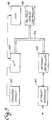
- FIG. 2discloses, in block diagram form, the internal configuration of an exemplary master controller.
- Overall operation of the master controlleris accomplished through a master single-board computer (SBC) 210 incorporating a processor and integral memory.
- SBCmaster single-board computer
- Operator device interfaces 212connect directly with the SBC for communication with programming devices, such as the standard keyboard and track ball, and supplemental external controllers and peripherals, such as the hand-held remotes, Magic Sheet, and hard copy printer.
- a processor communications busconnects the SBC to a multiple display controller 216 for the text and graphics displays and to a calculation coprocessor 218 and device control processor 220 to supplement the processing capability of the SBC.
- a calculation coprocessorallows rapid computation of light levels for dimmers controlled by the master console based on the various control inputs.
- the device control processorprovides an interface for the panel operator devices, generally designated 222, which include the slide controllers and designated function keypad inputs.
- direct output of DMX/CMX datais provided through the device control processor to a DMX/CMX interface 224.
- a network controller 226communicates to the SBC through the processor bus and attaches the master console to the LAN through network interface 228.
- VPCvideo peripheral controller
- VPCsare located on the network for use by designers, stage managers and others to monitor, control or design lighting remote from the master console.
- Devices supported by a VPCinclude remote text displays 136, remote graphic displays 138, dedicated function key input devices, such as remote keypads, 140, designer remotes 142 and Magic Sheets 144, remote submaster outriggers 146 and hand-held remotes 148.
- Exemplary use of the VPCwould be a stage manager's booth backstage in a theater, allowing the stage manager to view lighting cues on the text display to coordinate scene cues, actor entrances, etc.
- a second NPC configuration identified in the embodiment shown in the drawingsconstitutes an RF device interface 150, which provides communications through a radio frequency link 152 to roving design and control devices, such as Magic Sheets, designer remotes and hand-held remotes incorporating RF transceivers.
- roving design and control devicessuch as Magic Sheets, designer remotes and hand-held remotes incorporating RF transceivers.
- FIG. 3The internal configuration of an exemplary VPC is shown in FIG. 3.
- the VPCis connected to the LAN through a network interface 300, which communicates through network controller 302 to a microprocessor 304 on the microprocessor bus 306.
- the microprocessorcontrols the VPC, providing output to displays through a multiple display controller interface 308 connected to the processor bus and providing direct connection to the hand-held remote and other operator devices, generally designated 310.
- PNCssuch as the RF device interface
- RF device interfaceemploys a similar structure to that disclosed in FIG. 3, with appropriate interface modifications, such as the addition of an RF link between the microprocessor and operator devices. Flexibility obtained through the use of a network in the present invention allows PNCs to be developed with single or plural interfaces which may be attached at any T-connector on the LAN.
- NPCnetwork protocol converters
- Outputs from the NPCare provided to drive AMX dimmer racks 156 and CMX/DMX dimmer racks 158.
- the flexibility of the present systemallows the use of dimmer racks of any size including standard dimmer racks having 12, 24 or 48 single or dual dimmer modules (96 dimmers per rack).
- the present configuration of the embodiments shown in the drawingsallows designation of up to 8,192 dimmers for control on the LAN, with up to 4,096 dimmers controlled through an individual master console.
- FIG. 4demonstrates a present embodiment of the NPC.
- a master microprocessor 400provides overall control of the NPC.
- the master microprocessorcommunicates through a processor bus 402 with a slave mode microprocessor controller 404.
- An erasable programmable read-only memory (EPROM) 406 and random access memory (RAM) 408provide control software and operating data storage capability for the NPC.
- a network controller 410connected to the bus, provides communications to the LAN through a network interface 412. Communications with the dimmers is provided through DMX/CMX/AMX input/output interfaces 414.
- Additional interfaces for alternate control devicescan be incorporated in the NPC for additional local control flexibility.
- direct connection of DMX/CMX/AMX control devices to these interfacesallows non-networked control inputs into the NPC.
- an analog input interface 416in combination with an analog to digital converter 418 and an analog output interface 420, in combination with a digital to analog converter 422, provide direct analog input and output capability for the NPC for functional monitoring and control of the dimmer rack. In the embodiment shown in the drawings, between 8 and 24 analog inputs and outputs are provided.
- the internal intelligence in the NPCprovided by the master microprocessor and data storage capability allows the NPC to control complete configuration of the racks and dimmers connected to the NPC.
- a node name specifically identifying each NPCallows specified communication on the network and network source identification numbers of consoles or other input devices providing dimmer data input to the NPC are stored in memory.
- up to 16 controllersmay be present on the network, providing 16 I.D.'s for controller definition to the NPC. Availability of the dimmer data inputs for access by a controller and enabled/busy status for the inputs allows control of data received over the LAN by the NPC.
- Protocol types for the various control inputsare established, and source I.D.'s and priorities for "pile-on" of control data for the dimmers is provided.
- up to 7 DMX/CMX controllerscan be piled-on with priority.
- Each controller in the systemis given a priority of 5-to-1, or 0, with 5 being highest priority. Controllers with the same priority pile-on and ignore contributors of a lower priority. Priority 0 always piles-on for control selection.
- Rack level control parametersare provided through the analog input interface to the NPC with control outputs, such as fan activation, through the analog output interface.
- Individual dimmer parameterssuch as dimmer capacity and confituration are stored in memory in the NPC and individual dimmers may be named per dimmer circuit.
- a remap table for logical-to-physical definition of the dimmers in the rackis stored.
- Individual dimmer parameterssuch as target load, line regulation, cable resistance, response time, minimum and maximum values, phase control parameters, dimmer profile and dimmer alarm settings (over-temperature and load sensing) are stored for each dimmer.
- the NPCincorporates an external data storage interface 424 connected to the microprocessor bus for uploading and downloading NPC configuration to non-volatile storage, such as a memory card or magnetic disk system.
- a serial interface 426is provided in the NPC for direct connection of a personal computer or other device for configuration definition, as will be described in greater detail subsequently.
- the data contained in the NPCmay be monitored and/or updated through the LAN. This allows operators, designers, stage managers and others to receive direct feedback regarding operation of dimmers in the system.
- the flexibility afforded by the LAN in distribution of dimmer control datais also equally applicable to system feedback, which can be obtained at any LAN-connected console or VPC.
- Exemplary feedback parameters provided through the LAN for monitoring in the systeminclude individual dimmer name, control level (0-100%), output voltage, low load condition, overtemp condition and dimmer type.
- Memory capability in the NPCallows storage of a plurality of "looks” as previously described. Settings for the full compliment of dimmers controlled through the NPC are stored. In the present embodiment shown in the drawings, storage capacity for 99 "looks” is provided.
- the master microprocessor in the NPCmonitors control data provided by the LAN and/or local controllers. Upon loss of signal from the controllers, the microprocessor automatically institutes a preprogrammed "look.” Access to other "looks" stored in the memory can then be accomplished through a local controller, such as the hand-held remote. Changes between "looks” are automatically formatted by the NPC based on the dimmer parameters previously described.
- FIG. 5An exemplary embodiment for the dimmer racks used in the system is shown in FIG. 5.
- Dimmer data input to the rackis received on a DMX/CMX/AMX interface 500 connected to a microprocessor 502.
- the microprocessordecodes the dimmer data received and provides output to the dimmers through a digital-to-analog converter 504, providing direct pulse width modulation (PWM) output for "dumb” dimmers or through a universal asynchronous receiver/transmitter (UART) 506 for data transmission to "smart" dimmers.
- An analog interface 508, with associated A-to-D converter 510is provided for input of analog configuration or control parameters to the rack.
- Program and data storage for the microprocessoris provided in EPROM 512 and RAM 514.
- the configuration of the node controllers of the systemis accomplished through the use of a personal computer 162 attached to the network as shown in FIG. 1. Definition of all parameters and settings for each NPC are determined and entered into the PC prior to operation of the networked lighting system. The node configurations are then downloaded either through the LAN to the various nodes or the PC is individually attached to each node through the serial port and the node is preconfigured prior to attachment to the LAN.
- the necessary configuration settings of an NPCare the network name, dimmer source IDs of node input ports and Master Console dimmer data, pile-on assignments of output ports, remap assignments of source ID dimmers to output dimmers, DMX/CMX/AMX input protocol timing and enabling, and DMX/CMX/AMX output protocol timing and enabling.
- the only necessary configuration setting of a VPCis the network name.
- FIG. 7discloses, in block diagram form, an integration of the NPC into the dimmer rack.
- Dimmer racks with integrated nodes 160 for direct connection to the LAN as shown on FIG. 1employ the architecture of the embodiment shown in FIG. 7.
- the functions of the master microprocessor and slave mode controller of the NPC of FIG. 6are duplicated by the master microprocessor 700 and slave mode controller 702, with the master microprocessor controller additionally assuming the functions of the microprocessor 500 of the rack in FIG. 5.
- a device interface 704 for hand-held remote or rack monitorprovides direct communication to and from the integrated rack, with control level inputs received through DMX/CMX input interfaces 706 or through the LAN via the network interface 708 and network controller 710, which is attached to the microcontroller bus for direct communication to the master microprocessor.
- An analog interface 712 and associated A-to-D converter 714provide analog input to the slave mode controller for control functions.
- Multiple hardwired configuration switches located internal or external to the rackconnect to signal lines 716 feeding direct configuration data to the slave mode controller.
- the master microprocessorprovides direct output to a dimmer firing engine 718 with associated memory 720 for output of PWM data to "dumb” dimmers. Similarly the master microprocessor provides data directly to UART 722 for control of "smart" dimmers which, in turn, provide return communications through the UART to the master microprocessor.
- the memories 724 and 726, serial interface 728 and external data storage interface 730have similar functions to the NPC components described with regard to FIG. 4.
- the slave mode controller and master microprocessor of the integrated rackprovide sensing of power, temperatures and fan condition through A/D converter 732 and can provide that status data to the network.
- the integrated rackprovides a control output as a NPC for a companion standard DMX/CMX rack through DMX/CMX output interface 734.
- FIG. 6A functional diagram of software for an NPC of the embodiments in the drawings providing control to dimmer racks 160 of FIG. 1 and illustrated in FIG. 7, is shown in FIG. 6.
- the bubbles in FIG. 6identify the processes of the software, while arrows in the figure show data flow and hash-lined descriptions designate data storage.
- the initial processidentified as LEVEL CALCULATION, PILE-ON AND REMAP 610 receives inputs from the DMX direct connection consoles, NETWORK CONTROL LEVELS from the master console on the LAN and other ANALOG INPUTS.
- the LEVEL CALCULATIONcalculates the desired level for each controllable element in the system from the inputs and, based on the PILE-ON, REMAP, MIN./MAX.
- the output of defined levelsis provided to the DIMMER FIRING PROCESS, INCLUDING LINE REGULATION subroutine 612, which applies the DIMMER PROFILE provided from the DIMMER CONFIGURATION data based on the current line status identified by VOLTAGE A/D and ZERO CROSS data about the line.
- the calculated valuesare then output (OUT) to the rack for implementation.
- the CALCULATED VOLTAGESare also stored as DIMMER STATUS, and LEVELS provided from the level calculation are placed in memory as STORED LEVELS for operation by the CONFIGURE FEEDBACK AND ALARM subroutine 614, which provides data to the network for configuration and feedback and to the serial output for communication to the configuration PC.
- a DIMMER COMMUNICATION subroutine 616receives additional dimmer status communications (DIMMER COMM) from the rack and provides interactive communications to "smart" dimmers for information other than level data.
- the CONFIGURE FEEDBACK AND ALARMS subroutinealso receives input from the LAN or serial port for defining configuration of the NPC (NODE), mode of operation (MODE) or "look" data (LOOK NO.), which may be employed by the LEVEL CALCULATION, PILE-ON AND REMAP subroutine for generation of stored "looks". Analog inputs to the LEVEL CALCULATION, PILE-ON AND REMAP subroutine may also be employed for "look" selection or back-up from LOOK BACKUP data in memory, based on failure of DMX direct or network control level input.
- NODENPC
- MODEmode of operation
- LOOK NO."look" data
- Analog inputs to the LEVEL CALCULATION, PILE-ON AND REMAP subroutinemay also be employed for "look" selection or back-up from LOOK BACKUP data in memory, based on failure of DMX direct or network control level input.
Landscapes
- Circuit Arrangement For Electric Light Sources In General (AREA)
- Selective Calling Equipment (AREA)
Description
Claims (13)
- A theatrical lighting control network comprising:a local area network (100) having a plurality of connection points;first node controller (134) connected to said local area a network at a firstconnection point as a peripheral node controller, said peripheral node controller (134)having an interface for connection to a peripheral device (136 to 148);a second node controller (154) connected to said local area network at a secondconnection point as a node protocol converter (154) having a means for receiving settingstransmitted through the network, at least one means for translating the settings to a controlprotocol, and means for transmitting the control protocol as an output; andat least one rack (132) of a plurality of effect control elements (156 to 160) beingconnected to the output of said node protocol converter (154) and arranged to receive thecontrol protocol for operation of the effect control elements (156 to 160), whereby saidperipheral control devices (136 to 148) can directly control one of said effect controlelements (156 to 160).
- A network according to claim 1characterised by a control console having inputcontrols for operation to define desired settings of a plurality of said effect control elementsthe console feature having an interface connected to the network for transmitting settings tothe local area network.
- A network according to claim 2characterised in that the peripheral node controller(154) is a video peripheral controller and the peripheral device comprises a remote videodisplay.
- A network according to claim 3characterised in that the video peripheral controller(154) further has a second interface for connection of a remote control device (148) havingcontrols for defining desired effect settings.
- A network according to claim 1characterised in that said node protocol convertercomprises;
means for receiving non-networked effect settings; and
means for controlling pile-on of effect settings received over the network and thenot-networked effect settings. - A network according to any proceeding claimcharacterised by a control deviceconnected to the local area network at a third connection point, wherein the second nodecontroller (154) includes means for resolving settings received over the network from thefirst and third connection points.
- A network according to claim 6characterised in that the control device comprises acontrol console having input controls for operation to define desired settings of a pluralityof said effect control elements, said console having an interface means connected to thenetwork for transmitting the settings to the local area network.
- A network according to any proceeding claimcharacterised in that control devicecomprises a third node controller (150) connected to the local area network as a peripheralnode controller, said peripheral node controller (150) having an interface for connection toa second peripheral device.
- A theatrical lighting control network comprising:a local area network (100) having a plurality of connection points ;at least two node controllers (134, 154) connected to the local are a network as nodeprotocol converters, a first one of said node controllers, (134) having means for connectionof a standard protocol control console having input controls for operation to define desiredsettings of a plurality of effect control elements and means for transmitting the desiredsettings to the network, a second one of said node controllers (154) having a means forreceiving settings transmitted through the network, at least one means for translating thesettings to a control protocol, and means for transmitting the control protocol as an input;andat least one rack (132) of a plurality of effect control elements (156 to 160)connected to the output of the second one of said node protocol converters (154) andreceiving the control protocol for operation of the effect control elements (150-160).
- A network according to any proceeding claimcharacterised by a node protocolconverter having a communications interface connected to the local area network;
memory means for storing parameters and protocol information for operation of saidrack (132) of a plurality of effect control elements (156 to 160);
a controller connected to the communications interface and receiving effect settingsfrom at least one console connected to the network, said controller being connected to thememory means and having means for operating on said effect settings with said parametersand protocol information to establish an output protocol; and
an output interface connected to the controller for providing the output protocol tothe effect control elements of the rack. - A network according to claim 10characterised by means for receiving non-networkedeffect settings; and in that
the controller includes a means for controlling pile-on of effect settings receivedover the network and the non-networked effect settings. - A network according to any of the claims 1 to 9characterised by an integratedeffects rack and node protocol converter having;
a communications interface connected to the local area network;
memory means for storing parameters and protocol information for operation of saidrack of a plurality of effect control elements;
a controller connected to the communications interface and receiving effect settingsfrom at least one console connected to the network, said controller being connected to thememory means and having means for operating on said effect settings with said parametersand protocol information to establish effect control levels; and
a plurality of effect control elements connected to the controller and receiving theeffect control levels. - A network according to claim 6 and to claim 9characterised in that the second nodecontroller (154) is adapted to transmit feedback information to any monitoring deviceconnected anywhere on the local area network.
Applications Claiming Priority (3)
| Application Number | Priority Date | Filing Date | Title |
|---|---|---|---|
| US15248993A | 1993-11-12 | 1993-11-12 | |
| US152489 | 1993-11-12 | ||
| PCT/US1994/012980WO1995013498A1 (en) | 1993-11-12 | 1994-11-10 | Theatrical lighting control network |
Publications (3)
| Publication Number | Publication Date |
|---|---|
| EP0728275A1 EP0728275A1 (en) | 1996-08-28 |
| EP0728275A4 EP0728275A4 (en) | 1998-09-09 |
| EP0728275B1true EP0728275B1 (en) | 2005-01-12 |
Family
ID=22543149
Family Applications (1)
| Application Number | Title | Priority Date | Filing Date |
|---|---|---|---|
| EP95901850AExpired - LifetimeEP0728275B1 (en) | 1993-11-12 | 1994-11-10 | Theatrical lighting control network |
Country Status (6)
| Country | Link |
|---|---|
| US (2) | US5668537A (en) |
| EP (1) | EP0728275B1 (en) |
| AU (1) | AU701717B2 (en) |
| DE (1) | DE69434232D1 (en) |
| NZ (1) | NZ276610A (en) |
| WO (1) | WO1995013498A1 (en) |
Cited By (2)
| Publication number | Priority date | Publication date | Assignee | Title |
|---|---|---|---|---|
| US7868562B2 (en) | 2006-12-11 | 2011-01-11 | Koninklijke Philips Electronics N.V. | Luminaire control system and method |
| CN105636656A (en)* | 2013-10-14 | 2016-06-01 | I/P解决方案公司 | Dimmer for sport simulation environment |
Families Citing this family (170)
| Publication number | Priority date | Publication date | Assignee | Title |
|---|---|---|---|---|
| US5769527A (en)* | 1986-07-17 | 1998-06-23 | Vari-Lite, Inc. | Computer controlled lighting system with distributed control resources |
| US7397363B2 (en) | 1993-06-08 | 2008-07-08 | Raymond Anthony Joao | Control and/or monitoring apparatus and method |
| GB2325310B (en)* | 1995-04-28 | 2000-01-19 | Genlyte Group Inc | Multiple channel multiple scene dimming system |
| US10152876B2 (en) | 1996-03-27 | 2018-12-11 | Gtj Ventures, Llc | Control, monitoring, and/or security apparatus and method |
| US10011247B2 (en) | 1996-03-27 | 2018-07-03 | Gtj Ventures, Llc | Control, monitoring and/or security apparatus and method |
| US7253731B2 (en) | 2001-01-23 | 2007-08-07 | Raymond Anthony Joao | Apparatus and method for providing shipment information |
| US7277010B2 (en) | 1996-03-27 | 2007-10-02 | Raymond Anthony Joao | Monitoring apparatus and method |
| US5969485A (en)* | 1996-11-19 | 1999-10-19 | Light & Sound Design, Ltd. | User interface for a lighting system that allows geometric and color sets to be simply reconfigured |
| US6175771B1 (en)* | 1997-03-03 | 2001-01-16 | Light & Sound Design Ltd. | Lighting communication architecture |
| DE19715028B4 (en)* | 1997-04-11 | 2008-07-03 | Insta Elektro Gmbh | Bus-capable dimmers, electronic transformers and ballasts for brightness control of luminaires |
| US6714895B2 (en)* | 2000-06-28 | 2004-03-30 | A.L. Air Data, Inc. | Lamp monitoring and control unit and method |
| US6119076A (en) | 1997-04-16 | 2000-09-12 | A.L. Air Data, Inc. | Lamp monitoring and control unit and method |
| US6035266A (en)* | 1997-04-16 | 2000-03-07 | A.L. Air Data, Inc. | Lamp monitoring and control system and method |
| US6188933B1 (en)* | 1997-05-12 | 2001-02-13 | Light & Sound Design Ltd. | Electronically controlled stage lighting system |
| US6720745B2 (en) | 1997-08-26 | 2004-04-13 | Color Kinetics, Incorporated | Data delivery track |
| US6211626B1 (en) | 1997-08-26 | 2001-04-03 | Color Kinetics, Incorporated | Illumination components |
| US6292901B1 (en) | 1997-08-26 | 2001-09-18 | Color Kinetics Incorporated | Power/data protocol |
| US6016038A (en)* | 1997-08-26 | 2000-01-18 | Color Kinetics, Inc. | Multicolored LED lighting method and apparatus |
| US7038398B1 (en) | 1997-08-26 | 2006-05-02 | Color Kinetics, Incorporated | Kinetic illumination system and methods |
| US7242152B2 (en) | 1997-08-26 | 2007-07-10 | Color Kinetics Incorporated | Systems and methods of controlling light systems |
| US6975079B2 (en) | 1997-08-26 | 2005-12-13 | Color Kinetics Incorporated | Systems and methods for controlling illumination sources |
| US7014336B1 (en) | 1999-11-18 | 2006-03-21 | Color Kinetics Incorporated | Systems and methods for generating and modulating illumination conditions |
| US6528954B1 (en) | 1997-08-26 | 2003-03-04 | Color Kinetics Incorporated | Smart light bulb |
| US6777891B2 (en) | 1997-08-26 | 2004-08-17 | Color Kinetics, Incorporated | Methods and apparatus for controlling devices in a networked lighting system |
| US6869204B2 (en) | 1997-08-26 | 2005-03-22 | Color Kinetics Incorporated | Light fixtures for illumination of liquids |
| US7064498B2 (en) | 1997-08-26 | 2006-06-20 | Color Kinetics Incorporated | Light-emitting diode based products |
| US6548967B1 (en)* | 1997-08-26 | 2003-04-15 | Color Kinetics, Inc. | Universal lighting network methods and systems |
| US7385359B2 (en) | 1997-08-26 | 2008-06-10 | Philips Solid-State Lighting Solutions, Inc. | Information systems |
| US20020113555A1 (en) | 1997-08-26 | 2002-08-22 | Color Kinetics, Inc. | Lighting entertainment system |
| US6806659B1 (en) | 1997-08-26 | 2004-10-19 | Color Kinetics, Incorporated | Multicolored LED lighting method and apparatus |
| US7764026B2 (en)* | 1997-12-17 | 2010-07-27 | Philips Solid-State Lighting Solutions, Inc. | Systems and methods for digital entertainment |
| US6459919B1 (en) | 1997-08-26 | 2002-10-01 | Color Kinetics, Incorporated | Precision illumination methods and systems |
| US6888322B2 (en) | 1997-08-26 | 2005-05-03 | Color Kinetics Incorporated | Systems and methods for color changing device and enclosure |
| US7353071B2 (en)* | 1999-07-14 | 2008-04-01 | Philips Solid-State Lighting Solutions, Inc. | Method and apparatus for authoring and playing back lighting sequences |
| US7113541B1 (en)* | 1997-08-26 | 2006-09-26 | Color Kinetics Incorporated | Method for software driven generation of multiple simultaneous high speed pulse width modulated signals |
| US7139617B1 (en)* | 1999-07-14 | 2006-11-21 | Color Kinetics Incorporated | Systems and methods for authoring lighting sequences |
| US20040052076A1 (en)* | 1997-08-26 | 2004-03-18 | Mueller George G. | Controlled lighting methods and apparatus |
| US7427840B2 (en) | 1997-08-26 | 2008-09-23 | Philips Solid-State Lighting Solutions, Inc. | Methods and apparatus for controlling illumination |
| US7231060B2 (en) | 1997-08-26 | 2007-06-12 | Color Kinetics Incorporated | Systems and methods of generating control signals |
| US6936978B2 (en) | 1997-08-26 | 2005-08-30 | Color Kinetics Incorporated | Methods and apparatus for remotely controlled illumination of liquids |
| US7187141B2 (en) | 1997-08-26 | 2007-03-06 | Color Kinetics Incorporated | Methods and apparatus for illumination of liquids |
| US7482764B2 (en) | 1997-08-26 | 2009-01-27 | Philips Solid-State Lighting Solutions, Inc. | Light sources for illumination of liquids |
| US6965205B2 (en) | 1997-08-26 | 2005-11-15 | Color Kinetics Incorporated | Light emitting diode based products |
| US20030133292A1 (en)* | 1999-11-18 | 2003-07-17 | Mueller George G. | Methods and apparatus for generating and modulating white light illumination conditions |
| US6897624B2 (en) | 1997-08-26 | 2005-05-24 | Color Kinetics, Incorporated | Packaged information systems |
| US7186003B2 (en) | 1997-08-26 | 2007-03-06 | Color Kinetics Incorporated | Light-emitting diode based products |
| US6967448B2 (en) | 1997-08-26 | 2005-11-22 | Color Kinetics, Incorporated | Methods and apparatus for controlling illumination |
| US7352339B2 (en) | 1997-08-26 | 2008-04-01 | Philips Solid-State Lighting Solutions | Diffuse illumination systems and methods |
| US7132804B2 (en) | 1997-12-17 | 2006-11-07 | Color Kinetics Incorporated | Data delivery track |
| US7598686B2 (en) | 1997-12-17 | 2009-10-06 | Philips Solid-State Lighting Solutions, Inc. | Organic light emitting diode methods and apparatus |
| DE19803494A1 (en)* | 1998-01-29 | 1999-08-05 | Berchtold Gmbh & Co Geb | Procedure for manipulating an operating light |
| US9075136B1 (en) | 1998-03-04 | 2015-07-07 | Gtj Ventures, Llc | Vehicle operator and/or occupant information apparatus and method |
| CA2234486A1 (en)* | 1998-04-16 | 1999-10-16 | Will N. Bauer | 3d ready lamp |
| AU4083599A (en)* | 1998-05-18 | 1999-12-06 | Leviton Manufacturing Company, Inc. | Network based electrical control system with distributed sensing and control |
| US6188181B1 (en) | 1998-08-25 | 2001-02-13 | Lutron Electronics Co., Inc. | Lighting control system for different load types |
| CA2249761A1 (en)* | 1998-10-02 | 2000-04-02 | Will Bauer | Control system for variably operable devices |
| DE29902892U1 (en)* | 1999-02-18 | 2000-07-13 | CEAG Sicherheitstechnik GmbH, 59494 Soest | Emergency lighting system |
| US6175201B1 (en)* | 1999-02-26 | 2001-01-16 | Maf Technologies Corp. | Addressable light dimmer and addressing system |
| US20080140231A1 (en)* | 1999-07-14 | 2008-06-12 | Philips Solid-State Lighting Solutions, Inc. | Methods and apparatus for authoring and playing back lighting sequences |
| EP1224843A1 (en) | 1999-09-29 | 2002-07-24 | Color Kinetics Incorporated | Systems and methods for calibrating light output by light-emitting diodes |
| US6227674B1 (en)* | 1999-11-23 | 2001-05-08 | Rosco Incorporated | Oval, constant radius convex mirror assembly |
| US7049761B2 (en) | 2000-02-11 | 2006-05-23 | Altair Engineering, Inc. | Light tube and power supply circuit |
| JP2003524284A (en) | 2000-02-23 | 2003-08-12 | プロダクション・ソリューションズ・インコーポレーテッド | Sequential control circuit |
| JP4434424B2 (en)* | 2000-04-18 | 2010-03-17 | 株式会社ルネサステクノロジ | HOME ELECTRONIC SYSTEM, HOME SERVER DEVICE, AND COMPUTER-READABLE RECORDING MEDIUM CONTAINING PROGRAM FOR MAKING COMPUTER TO FUNCTION AS HOME SERVER DEVICE |
| US20040238637A1 (en)* | 2000-04-18 | 2004-12-02 | Metrologic Instruments, Inc. | Point of sale (POS) based bar code reading and cash register systems with integrated internet-enabled customer-kiosk terminals |
| US7642730B2 (en) | 2000-04-24 | 2010-01-05 | Philips Solid-State Lighting Solutions, Inc. | Methods and apparatus for conveying information via color of light |
| PT1422975E (en)* | 2000-04-24 | 2010-07-09 | Philips Solid State Lighting | Light-emitting diode based product |
| US7550935B2 (en)* | 2000-04-24 | 2009-06-23 | Philips Solid-State Lighting Solutions, Inc | Methods and apparatus for downloading lighting programs |
| US6564108B1 (en)* | 2000-06-07 | 2003-05-13 | The Delfin Project, Inc. | Method and system of auxiliary illumination for enhancing a scene during a multimedia presentation |
| US7202613B2 (en) | 2001-05-30 | 2007-04-10 | Color Kinetics Incorporated | Controlled lighting methods and apparatus |
| US20050275626A1 (en)* | 2000-06-21 | 2005-12-15 | Color Kinetics Incorporated | Entertainment lighting system |
| US7502034B2 (en)* | 2003-11-20 | 2009-03-10 | Phillips Solid-State Lighting Solutions, Inc. | Light system manager |
| WO2002011497A1 (en) | 2000-07-27 | 2002-02-07 | Color Kinetics Incorporated | Lighting control using speech recognition |
| US7042172B2 (en) | 2000-09-01 | 2006-05-09 | Color Kinetics Incorporated | Systems and methods for providing illumination in machine vision systems |
| US7303300B2 (en)* | 2000-09-27 | 2007-12-04 | Color Kinetics Incorporated | Methods and systems for illuminating household products |
| US6507158B1 (en) | 2000-11-15 | 2003-01-14 | Koninkljke Philips Electronics N.V. | Protocol enhancement for lighting control networks and communications interface for same |
| US6686831B2 (en)* | 2001-01-23 | 2004-02-03 | Invensys Systems, Inc. | Variable power control for process control instruments |
| US6801003B2 (en) | 2001-03-13 | 2004-10-05 | Color Kinetics, Incorporated | Systems and methods for synchronizing lighting effects |
| US7038399B2 (en) | 2001-03-13 | 2006-05-02 | Color Kinetics Incorporated | Methods and apparatus for providing power to lighting devices |
| US6676275B2 (en) | 2001-04-13 | 2004-01-13 | Farsight Llc | Portable, adaptable set lighting system |
| US7598684B2 (en) | 2001-05-30 | 2009-10-06 | Philips Solid-State Lighting Solutions, Inc. | Methods and apparatus for controlling devices in a networked lighting system |
| EP1413176A1 (en)* | 2001-07-23 | 2004-04-28 | Martin Professional A/S | Creating and sharing light shows |
| US20030036807A1 (en)* | 2001-08-14 | 2003-02-20 | Fosler Ross M. | Multiple master digital addressable lighting interface (DALI) system, method and apparatus |
| US6630800B2 (en)* | 2002-01-04 | 2003-10-07 | Hugewin Electronics Co., Ltd. | Remote-control device of lamp series control box |
| US6778084B2 (en) | 2002-01-09 | 2004-08-17 | Chang Industry, Inc. | Interactive wireless surveillance and security system and associated method |
| US6761470B2 (en)* | 2002-02-08 | 2004-07-13 | Lowel-Light Manufacturing, Inc. | Controller panel and system for light and serially networked lighting system |
| EP2749991A1 (en) | 2002-03-08 | 2014-07-02 | Quantum Interface, Llc | Electric device control apparatus |
| US10562492B2 (en) | 2002-05-01 | 2020-02-18 | Gtj Ventures, Llc | Control, monitoring and/or security apparatus and method |
| US7358679B2 (en) | 2002-05-09 | 2008-04-15 | Philips Solid-State Lighting Solutions, Inc. | Dimmable LED-based MR16 lighting apparatus and methods |
| US7023543B2 (en) | 2002-08-01 | 2006-04-04 | Cunningham David W | Method for controlling the luminous flux spectrum of a lighting fixture |
| CN1311359C (en)* | 2002-08-20 | 2007-04-18 | 星衍股份有限公司 | On-line photoelectric address setting method and device for realizing the method |
| US7300192B2 (en) | 2002-10-03 | 2007-11-27 | Color Kinetics Incorporated | Methods and apparatus for illuminating environments |
| US20040141321A1 (en)* | 2002-11-20 | 2004-07-22 | Color Kinetics, Incorporated | Lighting and other perceivable effects for toys and other consumer products |
| US7499860B2 (en)* | 2002-12-17 | 2009-03-03 | Microsoft Corporation | Computer system and method for enhancing experience using networked devices |
| ITTO20030165A1 (en)* | 2003-03-06 | 2004-09-07 | Space Cannon Vh S P A | LED LIGHT PROJECTOR |
| WO2004100624A2 (en)* | 2003-05-05 | 2004-11-18 | Color Kinetics, Inc. | Lighting methods and systems |
| US6925398B2 (en)* | 2003-07-07 | 2005-08-02 | Colorado Vnet, Llc | Water measurement apparatus and methods |
| US7170238B2 (en)* | 2003-07-30 | 2007-01-30 | Colorado Vnet, Llc | Control systems and methods |
| US7211968B2 (en)* | 2003-07-30 | 2007-05-01 | Colorado Vnet, Llc | Lighting control systems and methods |
| WO2005015350A2 (en)* | 2003-08-07 | 2005-02-17 | Production Resource Group, Llc | Interface computer for a stage lighting system |
| US7033044B2 (en)* | 2003-10-16 | 2006-04-25 | Farsight Llc | Horizontally and vertically adjustable lighting system and method |
| US7354172B2 (en) | 2004-03-15 | 2008-04-08 | Philips Solid-State Lighting Solutions, Inc. | Methods and apparatus for controlled lighting based on a reference gamut |
| US20050289279A1 (en)* | 2004-06-24 | 2005-12-29 | City Theatrical, Inc. | Power supply system and method thereof |
| US20100094478A1 (en)* | 2005-04-18 | 2010-04-15 | Gary Fails | Power supply and methods thereof |
| US20080170601A1 (en)* | 2004-06-25 | 2008-07-17 | Gary Fails | Oem radio transceiver and method thereof |
| US7432803B2 (en)* | 2004-06-25 | 2008-10-07 | City Theatrical Inc. | Wireless control system and method thereof |
| US7301468B2 (en)* | 2004-08-03 | 2007-11-27 | Taiwan Semiconductor Manufacturing Co., Ltd. | Method and apparatus for real time monitoring of an electric furnace heating coil |
| US7205729B2 (en)* | 2004-10-07 | 2007-04-17 | Barco, Naamloze Vennootschap | Control system and method for controlling lighting and video devices |
| US7460548B2 (en)* | 2005-04-19 | 2008-12-02 | Siemens Communications, Inc. | Optimally interworking SIP and QSIG call diversion and transfer |
| KR20080055892A (en)* | 2005-09-06 | 2008-06-19 | 코닌클리즈케 필립스 일렉트로닉스 엔.브이. | Method and apparatus for providing lighting settings for controlling the lighting system to produce the desired lighting effect |
| CA2559182C (en) | 2005-09-12 | 2017-05-09 | Acuity Brands, Inc. | Network operation center for a light management system having networked intelligent luminaire managers |
| US7817063B2 (en)* | 2005-10-05 | 2010-10-19 | Abl Ip Holding Llc | Method and system for remotely monitoring and controlling field devices with a street lamp elevated mesh network |
| JP2009534786A (en)* | 2006-04-21 | 2009-09-24 | ティーアイアール テクノロジー エルピー | Integrated power and control unit for solid state lighting |
| WO2008070981A1 (en)* | 2006-12-12 | 2008-06-19 | Tir Technology Lp | System and method for controlling lighting |
| DE102007026609B3 (en)* | 2007-06-08 | 2008-09-18 | Abb Ag | Multi-channel built-in dimmer |
| US7990082B2 (en)* | 2007-10-16 | 2011-08-02 | Robert Dilley | Methods and systems for operating and controlling theatrical lighting |
| US10321528B2 (en) | 2007-10-26 | 2019-06-11 | Philips Lighting Holding B.V. | Targeted content delivery using outdoor lighting networks (OLNs) |
| DE102007058166B3 (en)* | 2007-11-30 | 2009-05-14 | Ma Lighting Technology Gmbh | Lighting console for controlling a lighting system |
| US8118447B2 (en) | 2007-12-20 | 2012-02-21 | Altair Engineering, Inc. | LED lighting apparatus with swivel connection |
| US7712918B2 (en) | 2007-12-21 | 2010-05-11 | Altair Engineering , Inc. | Light distribution using a light emitting diode assembly |
| US20090198458A1 (en)* | 2008-01-29 | 2009-08-06 | Mcdermid John | Water measurement auto-networks |
| US8140276B2 (en) | 2008-02-27 | 2012-03-20 | Abl Ip Holding Llc | System and method for streetlight monitoring diagnostics |
| US8360599B2 (en) | 2008-05-23 | 2013-01-29 | Ilumisys, Inc. | Electric shock resistant L.E.D. based light |
| DE102008030920A1 (en)* | 2008-07-02 | 2010-01-07 | Ma Lighting Technology Gmbh | Lighting console for controlling a lighting system and method for operating a lighting control desk |
| US7976196B2 (en) | 2008-07-09 | 2011-07-12 | Altair Engineering, Inc. | Method of forming LED-based light and resulting LED-based light |
| US7946729B2 (en) | 2008-07-31 | 2011-05-24 | Altair Engineering, Inc. | Fluorescent tube replacement having longitudinally oriented LEDs |
| US8674626B2 (en) | 2008-09-02 | 2014-03-18 | Ilumisys, Inc. | LED lamp failure alerting system |
| US8256924B2 (en) | 2008-09-15 | 2012-09-04 | Ilumisys, Inc. | LED-based light having rapidly oscillating LEDs |
| US8444292B2 (en) | 2008-10-24 | 2013-05-21 | Ilumisys, Inc. | End cap substitute for LED-based tube replacement light |
| US8653984B2 (en) | 2008-10-24 | 2014-02-18 | Ilumisys, Inc. | Integration of LED lighting control with emergency notification systems |
| US8214084B2 (en) | 2008-10-24 | 2012-07-03 | Ilumisys, Inc. | Integration of LED lighting with building controls |
| US8901823B2 (en) | 2008-10-24 | 2014-12-02 | Ilumisys, Inc. | Light and light sensor |
| US8324817B2 (en) | 2008-10-24 | 2012-12-04 | Ilumisys, Inc. | Light and light sensor |
| US7938562B2 (en) | 2008-10-24 | 2011-05-10 | Altair Engineering, Inc. | Lighting including integral communication apparatus |
| US8556452B2 (en) | 2009-01-15 | 2013-10-15 | Ilumisys, Inc. | LED lens |
| US8362710B2 (en) | 2009-01-21 | 2013-01-29 | Ilumisys, Inc. | Direct AC-to-DC converter for passive component minimization and universal operation of LED arrays |
| US8664880B2 (en) | 2009-01-21 | 2014-03-04 | Ilumisys, Inc. | Ballast/line detection circuit for fluorescent replacement lamps |
| US8330381B2 (en) | 2009-05-14 | 2012-12-11 | Ilumisys, Inc. | Electronic circuit for DC conversion of fluorescent lighting ballast |
| TW201043088A (en)* | 2009-05-20 | 2010-12-01 | Pixart Imaging Inc | Light control system and control method thereof |
| US8299695B2 (en) | 2009-06-02 | 2012-10-30 | Ilumisys, Inc. | Screw-in LED bulb comprising a base having outwardly projecting nodes |
| US8773364B2 (en)* | 2009-06-22 | 2014-07-08 | Ma Lighting Technology Gmbh | Method for operating a lighting control console during color selection |
| EP2446715A4 (en) | 2009-06-23 | 2013-09-11 | Ilumisys Inc | LIGHTING DEVICE WITH LEDS AND SWITCHING CURRENT CONTROL SYSTEM |
| CA2792940A1 (en) | 2010-03-26 | 2011-09-19 | Ilumisys, Inc. | Led light with thermoelectric generator |
| US8540401B2 (en)* | 2010-03-26 | 2013-09-24 | Ilumisys, Inc. | LED bulb with internal heat dissipating structures |
| CA2794512A1 (en) | 2010-03-26 | 2011-09-29 | David L. Simon | Led light tube with dual sided light distribution |
| EP3389342B1 (en)* | 2010-04-09 | 2020-06-10 | eldoLAB Holding B.V. | Driver system for driving a plurality of led's |
| US8454193B2 (en) | 2010-07-08 | 2013-06-04 | Ilumisys, Inc. | Independent modules for LED fluorescent light tube replacement |
| CA2803267A1 (en) | 2010-07-12 | 2012-01-19 | Ilumisys, Inc. | Circuit board mount for led light tube |
| EP2633227B1 (en) | 2010-10-29 | 2018-08-29 | iLumisys, Inc. | Mechanisms for reducing risk of shock during installation of light tube |
| US8870415B2 (en) | 2010-12-09 | 2014-10-28 | Ilumisys, Inc. | LED fluorescent tube replacement light with reduced shock hazard |
| US20120153870A1 (en)* | 2010-12-16 | 2012-06-21 | Peter Kirkup | Lighting Control Desk with Removable Touch Screen Device |
| DE102011079891A1 (en)* | 2011-07-27 | 2013-01-31 | Zumtobel Lighting Gmbh | Lamp with DMX control gear |
| US9072171B2 (en) | 2011-08-24 | 2015-06-30 | Ilumisys, Inc. | Circuit board mount for LED light |
| US9184518B2 (en) | 2012-03-02 | 2015-11-10 | Ilumisys, Inc. | Electrical connector header for an LED-based light |
| US9163794B2 (en) | 2012-07-06 | 2015-10-20 | Ilumisys, Inc. | Power supply assembly for LED-based light tube |
| US9271367B2 (en) | 2012-07-09 | 2016-02-23 | Ilumisys, Inc. | System and method for controlling operation of an LED-based light |
| US10154121B2 (en) | 2012-09-28 | 2018-12-11 | Revolution Display, Llc | Control device, system containing the control device and method of using the same |
| CA2886876C (en)* | 2012-09-28 | 2019-06-11 | Revolution Display | Control device, system containing the control device and method of using the same |
| US9285084B2 (en) | 2013-03-14 | 2016-03-15 | Ilumisys, Inc. | Diffusers for LED-based lights |
| US10546441B2 (en) | 2013-06-04 | 2020-01-28 | Raymond Anthony Joao | Control, monitoring, and/or security, apparatus and method for premises, vehicles, and/or articles |
| US9267650B2 (en) | 2013-10-09 | 2016-02-23 | Ilumisys, Inc. | Lens for an LED-based light |
| CN106063381A (en) | 2014-01-22 | 2016-10-26 | 伊卢米斯公司 | LED-based light with addressed LEDs |
| US9510400B2 (en) | 2014-05-13 | 2016-11-29 | Ilumisys, Inc. | User input systems for an LED-based light |
| US9821738B2 (en) | 2014-06-30 | 2017-11-21 | Raymond Anthony Joao | Battery power management apparatus and method |
| US9871616B2 (en) | 2015-05-29 | 2018-01-16 | Abl Ip Holding Llc | Error detection and recovery in a DMX512 network |
| US10161568B2 (en) | 2015-06-01 | 2018-12-25 | Ilumisys, Inc. | LED-based light with canted outer walls |
| US10731831B2 (en) | 2017-05-08 | 2020-08-04 | Gemmy Industries Corp. | Clip lights and related systems |
| US12381953B2 (en) | 2019-07-01 | 2025-08-05 | Raymond Anthony Joao | Control, monitoring, and/or security, apparatus and method for premises, vehicles, and/or articles |
| US12380294B2 (en) | 2019-11-01 | 2025-08-05 | Raymond Anthony Joao | Control, monitoring, and/or security, apparatus and method for premises, vehicles, and/or articles |
| US11760227B2 (en) | 2021-02-15 | 2023-09-19 | Raymond Anthony Joao | Battery power management apparatus and method |
Family Cites Families (15)
| Publication number | Priority date | Publication date | Assignee | Title |
|---|---|---|---|---|
| US4947302A (en)* | 1982-11-19 | 1990-08-07 | Michael Callahan | Improvements to control systems for variable parameter lighting fixtures |
| US5329431A (en)* | 1986-07-17 | 1994-07-12 | Vari-Lite, Inc. | Computer controlled lighting system with modular control resources |
| US5209560A (en)* | 1986-07-17 | 1993-05-11 | Vari-Lite, Inc. | Computer controlled lighting system with intelligent data distribution network |
| US4969146A (en)* | 1987-11-10 | 1990-11-06 | Echelon Systems Corporation | Protocol for network having a plurality of intelligent cells |
| GB8727605D0 (en)* | 1987-11-25 | 1987-12-31 | Advanced Lighting Systems Scot | Programmable control system |
| US4837665A (en)* | 1987-12-02 | 1989-06-06 | Morpheus Lights, Inc. | Modular stage light system |
| FR2628335B1 (en)* | 1988-03-09 | 1991-02-15 | Univ Alsace | INSTALLATION FOR PROVIDING THE CONTROL OF SOUND, LIGHT AND / OR OTHER PHYSICAL EFFECTS OF A SHOW |
| US4949020A (en)* | 1988-03-14 | 1990-08-14 | Warren Rufus W | Lighting control system |
| US5004957A (en)* | 1989-01-06 | 1991-04-02 | Lee Colortran, Inc. | Dimming control circuit |
| US4972125A (en)* | 1989-02-09 | 1990-11-20 | Lee Colortran, Inc. | Plug-in dimmer module for lighting control systems |
| US4977484A (en)* | 1989-03-28 | 1990-12-11 | Lee Colortran Inc. | Dimmer rack |
| US5059871A (en)* | 1990-07-09 | 1991-10-22 | Lightolier Incorporated | Programmable lighting control system linked by a local area network |
| US5249140A (en)* | 1991-05-07 | 1993-09-28 | Vickers, Incorporated | Electrohydraulic distributed control system with identical master and slave controllers |
| CA2076171C (en)* | 1991-09-26 | 1998-08-18 | Brooks W. Taylor | Computer controlled lighting system with intelligent data distribution networks |
| MY108900A (en)* | 1992-04-21 | 1996-11-30 | Ppb Ltd | Apparatus for controlling electrical loads |
- 1994
- 1994-11-10EPEP95901850Apatent/EP0728275B1/ennot_activeExpired - Lifetime
- 1994-11-10WOPCT/US1994/012980patent/WO1995013498A1/enactiveIP Right Grant
- 1994-11-10DEDE69434232Tpatent/DE69434232D1/ennot_activeExpired - Lifetime
- 1994-11-10AUAU10938/95Apatent/AU701717B2/ennot_activeCeased
- 1994-11-10NZNZ276610Apatent/NZ276610A/enunknown
- 1996
- 1996-03-06USUS08/611,496patent/US5668537A/ennot_activeExpired - Lifetime
- 1997
- 1997-07-25USUS08/900,304patent/US6020825A/ennot_activeExpired - Lifetime
Cited By (2)
| Publication number | Priority date | Publication date | Assignee | Title |
|---|---|---|---|---|
| US7868562B2 (en) | 2006-12-11 | 2011-01-11 | Koninklijke Philips Electronics N.V. | Luminaire control system and method |
| CN105636656A (en)* | 2013-10-14 | 2016-06-01 | I/P解决方案公司 | Dimmer for sport simulation environment |
Also Published As
| Publication number | Publication date |
|---|---|
| AU1093895A (en) | 1995-05-29 |
| NZ276610A (en) | 1998-03-25 |
| US6020825A (en) | 2000-02-01 |
| AU701717B2 (en) | 1999-02-04 |
| EP0728275A4 (en) | 1998-09-09 |
| EP0728275A1 (en) | 1996-08-28 |
| WO1995013498A1 (en) | 1995-05-18 |
| US5668537A (en) | 1997-09-16 |
| DE69434232D1 (en) | 2005-02-17 |
Similar Documents
| Publication | Publication Date | Title |
|---|---|---|
| EP0728275B1 (en) | Theatrical lighting control network | |
| US7737819B2 (en) | Theatrical lighting control network | |
| US6664745B2 (en) | Apparatus for digital communications with multiparameter light fixtures | |
| US7671544B2 (en) | System and architecture for controlling lighting through a low-voltage bus | |
| US20050289279A1 (en) | Power supply system and method thereof | |
| US6545586B1 (en) | Method and apparatus for establishing and using hierarchy among remotely controllable theatre devices | |
| EP2277360B1 (en) | Configurable lighting devices under broadcast control | |
| KR101961898B1 (en) | A wireless control device for DMX-512 lightings and a method thereof | |
| KR101153976B1 (en) | Remote controller of stage lights using mimic board | |
| US20110103049A1 (en) | Universal color control matrix | |
| WO2018007282A1 (en) | Controlling an illumination source | |
| EP0823191B1 (en) | Improvements in or relating to lighting systems | |
| JPS62231587A (en) | Home control method | |
| JPH06111947A (en) | Dimmer | |
| JPH0879860A (en) | Centralized indoor distribution wiring management equipment and its control method | |
| JP2023109476A (en) | LIGHTING CONTROL SYSTEM, DIMENSION PANEL, LIGHTING CONTROL METHOD, AND PROGRAM | |
| JPH10302972A (en) | Lighting system | |
| JPH03183268A (en) | Remote control control device in multi-screen system | |
| JP2020140890A (en) | Lighting control device and lighting control system | |
| JPS62229686A (en) | lighting system | |
| JPH04368796A (en) | Lighting control device | |
| JPH11102605A (en) | Lighting equipment |
Legal Events
| Date | Code | Title | Description |
|---|---|---|---|
| PUAI | Public reference made under article 153(3) epc to a published international application that has entered the european phase | Free format text:ORIGINAL CODE: 0009012 | |
| 17P | Request for examination filed | Effective date:19960606 | |
| AK | Designated contracting states | Kind code of ref document:A1 Designated state(s):BE DE FR GB IT SE | |
| RHK1 | Main classification (correction) | Ipc:G05B 19/042 | |
| A4 | Supplementary search report drawn up and despatched | Effective date:19980722 | |
| AK | Designated contracting states | Kind code of ref document:A4 Designated state(s):BE DE FR GB IT SE | |
| RAP1 | Party data changed (applicant data changed or rights of an application transferred) | Owner name:NSI CORPORATION | |
| 17Q | First examination report despatched | Effective date:20000209 | |
| RAP1 | Party data changed (applicant data changed or rights of an application transferred) | Owner name:LEVITON MANUFACTURING CO., INC. | |
| RAP3 | Party data changed (applicant data changed or rights of an application transferred) | Owner name:LEVITON MANUFACTURING CO., INC. | |
| GRAP | Despatch of communication of intention to grant a patent | Free format text:ORIGINAL CODE: EPIDOSNIGR1 | |
| GRAS | Grant fee paid | Free format text:ORIGINAL CODE: EPIDOSNIGR3 | |
| GRAA | (expected) grant | Free format text:ORIGINAL CODE: 0009210 | |
| AK | Designated contracting states | Kind code of ref document:B1 Designated state(s):BE DE FR GB IT SE | |
| PG25 | Lapsed in a contracting state [announced via postgrant information from national office to epo] | Ref country code:IT Free format text:LAPSE BECAUSE OF FAILURE TO SUBMIT A TRANSLATION OF THE DESCRIPTION OR TO PAY THE FEE WITHIN THE PRESCRIBED TIME-LIMIT;WARNING: LAPSES OF ITALIAN PATENTS WITH EFFECTIVE DATE BEFORE 2007 MAY HAVE OCCURRED AT ANY TIME BEFORE 2007. THE CORRECT EFFECTIVE DATE MAY BE DIFFERENT FROM THE ONE RECORDED. Effective date:20050112 Ref country code:FR Free format text:LAPSE BECAUSE OF NON-PAYMENT OF DUE FEES Effective date:20050112 Ref country code:BE Free format text:LAPSE BECAUSE OF FAILURE TO SUBMIT A TRANSLATION OF THE DESCRIPTION OR TO PAY THE FEE WITHIN THE PRESCRIBED TIME-LIMIT Effective date:20050112 | |
| REG | Reference to a national code | Ref country code:GB Ref legal event code:FG4D | |
| REF | Corresponds to: | Ref document number:69434232 Country of ref document:DE Date of ref document:20050217 Kind code of ref document:P | |
| PG25 | Lapsed in a contracting state [announced via postgrant information from national office to epo] | Ref country code:SE Free format text:LAPSE BECAUSE OF FAILURE TO SUBMIT A TRANSLATION OF THE DESCRIPTION OR TO PAY THE FEE WITHIN THE PRESCRIBED TIME-LIMIT Effective date:20050412 | |
| PG25 | Lapsed in a contracting state [announced via postgrant information from national office to epo] | Ref country code:DE Free format text:LAPSE BECAUSE OF FAILURE TO SUBMIT A TRANSLATION OF THE DESCRIPTION OR TO PAY THE FEE WITHIN THE PRESCRIBED TIME-LIMIT Effective date:20050413 | |
| PLBE | No opposition filed within time limit | Free format text:ORIGINAL CODE: 0009261 | |
| STAA | Information on the status of an ep patent application or granted ep patent | Free format text:STATUS: NO OPPOSITION FILED WITHIN TIME LIMIT | |
| 26N | No opposition filed | Effective date:20051013 | |
| EN | Fr: translation not filed | ||
| PGFP | Annual fee paid to national office [announced via postgrant information from national office to epo] | Ref country code:GB Payment date:20061108 Year of fee payment:13 | |
| GBPC | Gb: european patent ceased through non-payment of renewal fee | Effective date:20071110 | |
| PG25 | Lapsed in a contracting state [announced via postgrant information from national office to epo] | Ref country code:GB Free format text:LAPSE BECAUSE OF NON-PAYMENT OF DUE FEES Effective date:20071110 |