EP0725523B1 - Transaction message routing in digital communications networks - Google Patents
Transaction message routing in digital communications networksDownload PDFInfo
- Publication number
- EP0725523B1 EP0725523B1EP95480177AEP95480177AEP0725523B1EP 0725523 B1EP0725523 B1EP 0725523B1EP 95480177 AEP95480177 AEP 95480177AEP 95480177 AEP95480177 AEP 95480177AEP 0725523 B1EP0725523 B1EP 0725523B1
- Authority
- EP
- European Patent Office
- Prior art keywords
- message
- node
- routing
- naps
- destination
- Prior art date
- Legal status (The legal status is an assumption and is not a legal conclusion. Google has not performed a legal analysis and makes no representation as to the accuracy of the status listed.)
- Expired - Lifetime
Links
Images


Classifications
- H—ELECTRICITY
- H04—ELECTRIC COMMUNICATION TECHNIQUE
- H04L—TRANSMISSION OF DIGITAL INFORMATION, e.g. TELEGRAPHIC COMMUNICATION
- H04L45/00—Routing or path finding of packets in data switching networks
- H—ELECTRICITY
- H04—ELECTRIC COMMUNICATION TECHNIQUE
- H04L—TRANSMISSION OF DIGITAL INFORMATION, e.g. TELEGRAPHIC COMMUNICATION
- H04L45/00—Routing or path finding of packets in data switching networks
- H04L45/34—Source routing
Definitions
- This inventionrelates to the routing of digital messages through a packet communication network and, more particularly, to the use of flexible routing control formats and to editing capabilities distributed throughout the network for altering or enhancing routing information associated with digital messages at one or more intermediate points in a multi-node route through the communication network.
- Message routingis a function that enables a network user program (or agent) to send a message to another user program.
- Packet communication systemsdo not reserve transmission facilities for the duration of a session, but only reserve individual links in the transmission path, and only for the duration of a packet. It is therefore necessary to provide a mechanism for routing digital packets through the packet network. All packet communications networks utilize a header, preceding the data packet, which contains sufficient information to control the routing of that packet from the origin of the packet to the destination of the packet.
- ANRAutomatic Network Routing
- Message broadcasting, or multi-castingutilizes a single identification of a multi-cast tree in the header and, at each intermediate node, utilizes the tree identifier to select the outgoing link or links which are included in the multi-cast tree.
- Yet other routing algorithmsutilize the destination address in the header to select, using a routing table, the next link in the route.
- One other routing techniqueconsists in using 'self routing packets' which convey a list of the physical port address to be used by the successive nodes for switching the packets. Each intermediate node reads the output port address to which the packet should be routed.
- the European patent application EP 0 608 653 of International Business Machinediscloses a method to route the 'self routing packets' which reduces the processing time in the intermediate nodes and allows the originator nodes to receive notifications in case of abnormal conditions..
- the routing code read from the routing list conveyed by the packetis XORed with the address of the input port to obtain the address of the output port.
- the routing codesare also rearranged in the node the successive nodes into the routing list.
- a direction indicatoris also arranged and passed to the next nodes with the packet.
- the determination of the links in a route from origin to destinationis preferably deferred until after the packet is launched on the network.
- address directoriesmay be used along the route to resolve destination names or addresses in view of the content of the data, e.g., routing "800" telephone numbers or routing credit card transactions based on credit card numbers.
- Routing flexibility'ssuch as those described above are important for many real time applications.
- all of the prior art schemes for providing routing flexibility in a packet networkare application-dependent, thus requiring separate routing mechanisms for different transaction codes or different user identifications. Since there is no upper bound on the number of such routable data objects, the complexity of the routing mechanisms can likewise grow without bounds.
- NAPSNaming and Addressing Parameter String
- the routing headerincludes a NAPS structure which includes one or more message routing addresses, each of which may include, in turn, an identification of an intermediate or destination node, an identification of an application or routing agent program, and a user-specified parameter that is passed to the agent program to properly process the destination information, e.g., a directory identifier.
- the RSreceives the message at a node and performs the generic NAPS processing that is common to all nodes.
- the RSreceives a message, analyzes the NAPS top element fields, and sends the message to another node if the destination node is a remote node, or sends the message to a local application agent program or to a local RAP if the destination node is the message-receiving node.
- the RSincludes look-up tables to assist in the NAPS processing. More particularly, a Destination Node Table (DNT) is used to select the next node in the route to the specified destination node.
- a Local Agent Table (LAT)identifies all of the local agents connected to the local node.
- a RAPis a special type of agent that executes special logic that updates the NAPS and the passes the message to the RS to route the message toward its next processing point, which could be an application agent program or another RAP.
- Nodes of the network which contain RS and RAPsare called "Message Routing (MR)" nodes and are used to provide all of the routing flexibility of the present invention.
- packet networks equipped with NAPS, RS and RAPs as described aboveprovide routing flexibility for all types of data packets without the necessity of designing and implementing separate flexibility for each of many classes of data packets. This flexibility can therefore be invoked by all users of the network to implement the particular routing processing required for the packets utilized by that user.
- This application-independent aspect of the flexible routing mechanisms of the present inventionis of particular importance in reducing the cost and complexity of the network architecture.
- the single NAPS/RS/RAPS mechanism of the present inventioncan be applied to an arbitrarily large number of different data packet classes by allowing the user to specify significant variables in the route editing facility.
- the editing functionis under the control of an edit table which contains specific directions for editing a particular NAPS.
- the route editing mechanismis under the control of one or more such tables specifying the editing steps necessary to transform the current NAPS into the desired NAPS.
- the provision of a standard form header and header processing capability in at least some of the intermediate nodes of the networkpermits deferred routing to accommodate not only link failures or congestion, but also to permit data-dependent routing, routing-dependent data processing and administrative processing at inter-network boundaries.
- Message originating location 10comprises an originating message routing agent 12 and a message routing node 11.
- Originating agent 12is a computer program which requests the use of the transmission network 13 to transmit a message to a destination agent 23 (another computer program at a remote location).
- destination location 24includes a message routing node E (22) and a message routing destination agent 23.
- a message routing agentis any program that uses the message routing function.
- message routing agentssuch as 12 and 23 comprise resource managers that provide many other services besides message routing, such as message queuing.
- the packet communications system of FIG. 1includes a plurality of message routing nodes A-I interconnected by transmission links.
- node A (11)is connected to nodes B (14) and G (15)
- node Bis connected to nodes C (18) and E (22)
- node Gis connected to node H (16)
- node His connected to nodes C (18) and I (21)
- node Iis connected to node E (22).
- the interconnections of the message routing nodes A through Iis only illustrative and many more nodes could be included in the packet network, interconnected by many other transmission links.
- the message routing nodes A through Iutilize information in the headers of the packets launched on the network to route the packet to the appropriate destination node.
- Message routing networkssuch as network 13 are connectionless networks in which many messages from many different origins may be flowing simultaneously on a given connection between a pair of nodes.
- the function of the nodeis to forward each of the messages, received from a connected node, toward its ultimate destination.
- Routing agent program 17is associated with node H (16) while routing agent program 19 is associated with node C (18).
- RAPS 17 and 19are used to process the headers of packets launched on the network 13 to assist in determining the actual ultimate destination of the attached packet, using information found in the header of the packet.
- the purpose of the routing agent programsis to permit the selection of the message destination to be deferred until the message is actually traversing the path to the destination node. Such routing flexibility is important for many real time applications such as:
- a Naming and Addressing Parameter String(NAPS), consisting of one or more address elements, is included in the header of each message launched on the network. More particularly, the NAPS structure is used to specify both the source address and the destination address in the message header. The desired flexibility is implemented by the interaction of these NAPS with the RAPS. More particularly, the RAPS can be used to:
- NAPSNAPS network address
- ASN.1ISO Abstract Syntax Notation One
- the NAPSis defined recursively, permitting the specification of a sequence of successive, intermediate locations for message processing, yielding a very powerful naming and addressing facility.
- FIG. 2there is shown a graphical representation of a packet message comprising a packet header 30, and a data block 37 associated with header 30.
- Header 30comprises a plurality of message routing addresses 34, 35, ..., 36, each comprising a node identification field 31, an agent name field 32 and an agent parameter field 33.
- Most networking protocolsallow one destination and one origin address per message.
- the message routing method and apparatus of the present inventionpermit both the destination and the origin addresses to consist of an arbitrarily deep stack of address elements.
- each NAPS elementmay consist of three components (NodeName, AgentName and AgentParm), any of these components can be null, having the implications to be discussed later.
- nodes and agentsmay, for example, have global names which are unique throughout the network in which they are used. To this end, such names can follow existing network naming conventions which are intended to be global.
- Many existing network architecturessuch as IBM's SNA, ARPA's TCP/IP and ISO's X.400 E-mail, have an already-existing naming authority hierarchy which allow network administrators to create globally unique names by registering company or business unit names and creating new names by appending subunit names to the registered name. For example, suppose a company is name "ABC, Inc.” and the network administrator for the "DE" division of ABC, Inc.
- Pipescan be implemented using logical connections provided by existing communications subsystems such as the SNA sessions, OSI associations or TCP/IP connections.
- Each message of the format of FIG. 2may include a bit string representing the message class of the message.
- the message classspecifies the routing properties required for the message (e.g., SECURE or EXPEDITE) and acts as a filter to ensure that a chosen path satisfies the requirements of the message.
- the power of the message routing technology outlined in FIGS. 1 and 2lies in its ability to route messages even though the originator of the message does not know the identity of or the location of the ultimate recipient of the message.
- These capabilitiesare implemented by the NAPS and the following three tables: Local Agent Table AgentName Agent Process Access and status Destination Node Routing Table DestinationNodeName MessageClass Pipe Process Access and Status NAPS Edit Table Node Name Agent Name Action New Node Name NewAgent Name NewAgent Parameter
- the NodeName fieldhas the form of a global name as discussed above, and should nominally be the name of an existing message routing node on the network. In reality, this name can be anything and will be processed as discussed below in connection with the routing algorithm of FIGS. 3 through 6.
- Real MR global namesshould be unique among all of the nodes that will send messages to this node. This is most easily accomplished by selecting a name that is globally unique across all node names around the world, as described above.
- the AgentName fieldalso has the form of a global name and is nominally the name of an existing Message Routing agent, but in reality can be null or may represent a class or a set of agent, or anything else. This will likewise be explained in connection with the routing algorithm of FIG. 3.
- the AgentNamemust be unique among all of the agents that reside on that node.
- agent names that represent classes or sets of agentsshould be unambiguous across all nodes where other agents may reference the agent name.
- the Passport Credit Card Companymay choose to deploy an agent name "Passport Authorize" for a set of credit card authorization applications distributed across a set of networks.
- the U.S. Customs servermight deploy the same agent name for an application that authorizes the renewal of passports.
- the network administratorsare responsible for ensuring that it is impossible for a message sent to one of the applications to arrive at the other.
- the use of one of the above-described network architecture global naming standardsinsures global uniqueness.
- AgentParm fieldis for the use of agents to pass small amounts of data between themselves.
- Routing Agent ProgramsRAPs
- RAPsRouting Agent Programs
- Routing Servicesreceives messages from three different sources:
- the routing algorithm according to the present inventionwhich is implemented in each MR node of FIG. 1 begins in start box 70 and enters box 71 to receive a message from a local or a remote Agent on the network system.
- the RS of FIG. 3operates only on the top element of the destination NAPS in the header of the message.
- the decision box 73examines the NodeName field (TABLE 2) in this top element of the destination NAPS. This NodeName field can have one of four values:
- the RSassumes that the message is destined from some agent or RAP on this node. As will be described later, this may not be the case. If the NodeName field in the top element of the NAPS stack contains either the name of this node or is null, decision box 73 assumes that the destination agent is this node and goes to decision box 75 to search the Local Agent Table (TABLE 1 above).
- the Local Agent Tableis a list of all agents and Routing Agent Programs (RAPS) that are actively running on this node.
- box 84is entered where the message is queued to the agent or RAP identified in the Local Agent Table. Box 85 is then entered to return an acknowledgment to the calling program and the process of FIG. 3 terminated in box 86. If the name is not found in the Local Agent Table, as determined by decision box 75, or if the agent name in the NAPS is null, box 76 is entered to attempt to edit the address element at the top of the NAPS. This editing process is described in detail in connection with FIGS. 4 and 5.
- decision box 74is entered to attempt to determine the identity of the pipe to be used to forward the message on its way to the named identification node.
- the Destination Node Table(TABLE 2) is searched, using the combination of the NodeName in the NodeName field and the message class of the message. If a suitable pipe cannot be found, as determined by decision box 78, box 76 is entered to attempt to edit the NAPS, as will be described in connection with FIGS. 4 and 5.
- box 80is entered to queue the message for transmission on the pipe so identified.
- Box 81is then entered to return an acknowledgment to the calling program.
- Terminal box 86is then entered to terminate the process of FIG. 3.
- address editing box 76is entered, due to a failure in the searches in either box 74, 75 or 78, the processes of FIGS. 4 and 5 are used to attempt to edit the destination NAPS.
- Decision box 77is then entered to determine if the address was actually updated in box 76. If so, box 73 is re-entered to re-analyze the newly edited NAPS. If no editing has taken place in the most recent attempt in box 76, as determined by decision box 77, decision box 79 is entered to determine the type of error return to be used, either synchronous or asynchronous.
- the program that calls the process of FIG. 3specifies whether it wants a synchronous or an asynchronous error return. A synchronous return returns control to the caller with an error return code in box 82.
- the error handlersends a negative acknowledgment to the sender at the origin node.
- box 85is then entered to return an OK to the RS caller because responsibility for the message has been transferred to the error handler and the caller need not react. In either event, the process of FIG. 3 terminates in terminal box 86.
- box 76 of FIG. 3can be simple or very sophisticated. While a simple editor will be described in connection with FIGS. 4 and 5, it is clear that much more complex editors can be used as required by the various users of the network. As a minimum, however, such an editor must at least be able to pop a NAPS element off of the destination address stack when it is no longer needed, must be able to add a new NAPS element onto the destination address stack to provide new routing information and yet preserving the existing routing information for processing at another routing point along the message path, and must be able to replace one or more NAPS element fields to correct or amend the required information. Such an editor is shown in FIGS. 4 and 5.
- FIG. 4there is shown a flow chart of a NAPS editor which is table-driven by a table such as that shown in TABLE 3.
- the flow chart of FIG. 4does the table look-ups necessary to control the editor functions while FIG. 5 is a flow chart of the process for actually performing the edits.
- the flow chart of FIG. 4starts in start box 90 where box 91 is entered to unpack the fields from the top NAPS element of the destination address. The return pointer is then initiated to null, the return value used when the edit attempt is unsuccessful. Box 93 is then entered to search the edit table (TABLE 3 above), using the NodeName and AgentName values from the NAPS as the initial search keys.
- the NodeName portion of the search keyis first held constant while the AgentName portion is searched in box 93, increasingly generalized by successively substituting increasingly more general wildcard values until either a matching entry is found or until all wildcards have been used, as determined by decision box 94.
- This procedureassumes that the AgentName is a sequence of sub-strings separated by periods, i.e., a global name in one of the standard global formats described above. If a match is found, box 99 is entered to update the destination NAPS. If no match is made with the AgentName field, as determined by decision box 94, box 95 is entered where the NodeName field is searched in the edit table.
- the search in box 95is also increasingly generalized by successively substituting increasingly more general wildcard values until either a matching entry is found or until all wildcards have been used, as determined by decision box 96.
- the AgentName valueis reset to the original value.
- box 99is entered to update the destination NAPS, as will be discussed in connection with FIG. 5.
- box 97is entered to set the return pointer to the new NAPS produced in box 99.
- the process of FIG. 4terminates in box 98. Note that, if no NAPS editing takes place due to the failure to find an edit table entry, the initialized null returned pointed is returned, signaling a routing error.
- the destination NAPS updating procedure of box 99 in FIG. 4is shown in detail in FIG. 5.
- FIG. 5there is shown a flow chart of the destination NAPS updating procedure referred to in connection with box 99 of FIG. 4.
- box 101is entered to initialize the return destination element to a null value.
- Box 102is then entered to test the NewNodeName and NewAgentName values obtained from the Edit Table (TABLE 3) in the process of FIG. 4 are compared to the NodeName and AgentName values in the top NAPS element of the message header. This test prevents infinite recycling of the editor due to errors in the edit table. If these values are the same, box 105 is entered to return the null values (initialized in box 101) to the calling program, indicating a edit failure.
- edit table values of NewNodeName and NewAgentNameare different from the values in the top NAPS element, as determined by decision box 103, box 104 is entered to execute the edit action specified in the edit table.
- these edit actionsinclude at least pop, push and replace the top element of the NAPS.
- Other editing actionsare, of course, possible and will be obvious to those skilled in the art. These editing actions are under control of the edit table and can be specified by the network administrator, by the source user or by the destination user of the network.
- box 108is entered where the top element in the NAPS stack is popped off of the stack and the return pointer is set to the new top element. If there are no more NAPS components in the stack, the message is considered undeliverable and a null pointer is set in box 105, indicating an edit failure. If a new NAPS element is constructed from the values in the NewNodeName, NewAgentName and NewAgentParm fields of the NAPS edit table entry, box 105 is entered where that new NAPS element is pushed onto the NAPS stack in the header of the message. These new NAPS element field values can be null or a control character used to replicate the previous value in that field.
- the return pointeris set in box 105 to point to the newly pushed NAPS element. If one or more fields of the top NAPS element are to be replaced, box 109 is entered where the desired NAPS elements fields are replaced. As before, a null value or a replacement symbol can be used as the replacement value for any field value. Again, the return pointer is set in box 105 to reference the top NAPS element. The process of FIG. 5 terminates in return box 107.
- the operation of the NAPS editing function in the RAPs of the present inventionwill be illustrated in detail in connection with the packet communications system of FIG. 6.
- the system of FIG. 6is for a credit card authorization application between a plurality of retailer networks 122 and 127 and a plurality of bank networks 129 and 130, using a backbone credit card network 124.
- Message routing nodes 121, 123, 125, 126, 128, 131 and 133serve not only as routing editing RAPs but, except for node 133, also as inter-network connection nodes shared by the two networks on which they appear.
- each of networks 122, 124, 127, 129 and 130includes a plurality of other internal nodes interconnecting a plurality of users with each other for the purposes of communicating intra-network information as is well known in the art.
- a source user 120for example a point-of-sale (POS) terminal in a retail establishment, issues a message requesting a charge authorization from the bank which has issued the customer's credit card. This request message is delivered to the bank destination user 132 which returns an authorization (or denial) of credit message back to the source user 120.
- POSpoint-of-sale
- POSpoint-of-sale
- the point-of-sale terminalis called an MR client node, indicating that the POS terminal knows nothing about routing messages, but relies on the adjacent MR node 121 to provide this function.
- the global node name of the POS terminalis (SNA, USSEERAW.POS234X1).
- the message constructed by the POS terminalis as follows, omitting details not related to this example:
- node 121When this message is passed to entry node 121, node 121 first examines the NodeName field of the top element of the destination NAPS (box 73, FIG. 3). As can be seen above, this field is null and therefore node 121 looks in the Local Active Agent Table for an active agent or Routing Agent Program with the name (IP,Authorize.Passport.com). Since there will be no entry to match this agent name, the message will be submitted for NAPS editing (box 76, FIG. 3). The destination NAPS edit process pushes a new element onto the destination NAPS that contains the node name "(SNA,USSEERAW.AWSRV193)," the global name of routing server node 133 inside of network 122 and which is enroute to message routing node 123. When the editing is done, the message appears as follows:
- the internal message routing node 133 within network 122will also try to route this message.
- the destination node name fieldis examined (box 73, FIG. 3)
- the destination nodewill be this node ("ON_ME,” box 73, FIG. 3)(node 133) and the agent name field will be examined.
- the agent name fieldcontains "null.”
- Node 133therefore attempts to edit the top NAPS element, as shown in flow chart of FIG. 3.
- the edit table in node 133is consulted and the following entry is found: Edit Table Node Name Agent Name Action New Node Name NewAgent Name (SNA,USSEERAW.AWSRV193) null Pop null null null
- Routing node 133will now try to route the message according to the new NAPS element ("YES" in box 77, FIG. 3). Since the node name field of the new NAPS is still "null," the routing node 133 searches the agent table (box 75 in FIG. 3) for the agent or Routing Agent Program (RAP) with the designation (IP,Authorize.Passport.com). Since no such entry exists, the NAPS will be submitted to the editor for editing.
- RAPRouting Agent Program
- An edit table entryis found as follows: Edit Table Node Name Agent Name Action New Node Name NewAgent Name null (IP, Authorize.-Passport.com) Push (IP, GWSEERS9.-Passport.com) (IP, Gateway.-Passport.com)
- the RSdetects that the message is destined for this node and attempts to route the message to an agent or RAP with the name (IP,Gateway.Passport.com). This time, it finds that a RAP with that name exists and is active, and queues the message to that RAP.
- the RAPWhen the message is delivered to the RAP identified as "(IP,Gateway.Passport.com)," the RAP, will first pop the top element off of the destination NAPS stack, so the message will once again look like it did when it was first created. This RAP will then examine the AgentParm field of the new top NAPS element to determine the credit card number. Using a translation algorithm proprietary to the credit card company, the credit card number is translated to the name of the bank owning the credit card account.
- the bank operating bank network 130is the bank owning the credit card account.
- the editing facilities at this RAPwill then push a new destination element onto the destination NAPS stack, and will push a new source element onto the source NAPS stack, resulting in a message looking as follows:
- the new element on the destination NAPS stackwill route the message to a RAP on a gateway node owned by BANC-TWO, e.g., node 125.
- the new element on the origin NAPS stackwill assist the routing of the return message.
- the routing nodes in network 124attempt to reroute the message, they will now see that the message is destined for another node. By consulting their Destination Node Routing Tables, these nodes will determine which pipes to queue the message for transport to the next node on the route.
- the messagewill be received at node 125, identified as (IP,GWPassport3.Banc-Two.com) in the destination NAPS.
- the Routing Serviceswill route the message to the RAP named "(IP,Gateway.Banc-Two.com)."
- This RAPwill pop the top element off of the destination NAPS stack and examine the element underneath. It will then note that the original AgentName field has requested a credit authorization transaction.
- the AgentParm fieldis then examined to confirm that the bank requested is the Banc-Two, again by translating the credit card number. It can be assumed that Banc-Two has decentralized its operation and includes a number of different credit card databases. It is therefore necessary for the RAP to determine to which computer database to route the message.
- the RAPwill then modify the remaining element of the NAPS stack, and push yet another element onto the origin NAPS stack so that the message now looks as follows:
- a routing node within network 130When a routing node within network 130 attempts to route this message, it will see that the message is destined for a different node. consulting its Destination Node Routing Table, it will forward the message according to the pipes found in this table. The message will thereby be forwarded across network 130 until it reaches node 131, identified as (SNA,USBTWOAW.REGION12). At node 131, the message will be routed to the destination user 132, identified in the message as (UNDEF,CCAUTH).
- the user agent 132is responsible for authorizing all credit card transactions from all of the credit card retailers with which BANC-TWO is associated. User agent 132 will perform the requested authorization and build a return message to be sent back to the originating point-of-sale (POS) terminal.
- the destination NAPS stack of the incoming messageis moved to the origin NAPS stack of the return message
- the origin NAPS stack of the incoming messageis moved to the destination NAPS stack of the return message
- the responseis placed in the AgentParm field of the deepest element in the resulting destination NAPS stack.
- the return messagewill look like this:
- This messageis launched to node 131 where the Routing Program will examine the NodeName field and, seeing that the message is for another node with consults its Destination Node Routing Table and queue the message for the appropriate pipe.
- the messagewill make its way across the bank's network 130 until it reaches node 125, identified as (IP,GWPassport3.Ban-Two.com).
- node 125identified as (IP,GWPassport3.Ban-Two.com).
- the messageis submitted for NAPS editing (since the AgentName is null) and an appropriate entry in the Edit Table will cause the top entry to be popped off of the Destination NAPS stack.
- the messageis then routed across the credit card network 124 to node 123, identified as (IP,GWSEERS9.Passport.com).
- the messageis again submitted for NAPS editing and, in response to an appropriate entry in the NAPS edit table, this entry will be popped off of the destination NAPS stack to expose the bottom NAPS entry.
- the messageis then routed across the retailer network 122, through node 133, to the node 121, identified as (SNA,USSEERAW.POS234X1).
- the messageis then routed to the point-of-sale user 120, identified as (SNA,USSEERAW.CCTRANS), where the message in the AgentParm field will be displayed to the retail clerk.
- NAPS stacksto represent both the origin address and the destination address for user messages to be routed across a plurality of different packet communications networks. Routing programs at intermediate nodes in the different networks edit the NAPS elements to ensure the forwarding of the message to the appropriate destination even when the originating station does not know the address of the ultimate destination.
- a non-address field(AgentParm) is included in the NAPS element to assist in both routing and processing of the message.
Landscapes
- Engineering & Computer Science (AREA)
- Computer Networks & Wireless Communication (AREA)
- Signal Processing (AREA)
- Computer And Data Communications (AREA)
- Data Exchanges In Wide-Area Networks (AREA)
- Information Retrieval, Db Structures And Fs Structures Therefor (AREA)
- Telephonic Communication Services (AREA)
Description
- This invention relates to the routing of digital messages througha packet communication network and, more particularly, to the useof flexible routing control formats and to editing capabilitiesdistributed throughout the network for altering or enhancingrouting information associated with digital messages at one ormore intermediate points in a multi-node route through thecommunication network.
- Message routing is a function that enables a network user program(or agent) to send a message to another user program. Packetcommunication systems do not reserve transmission facilities forthe duration of a session, but only reserve individual links inthe transmission path, and only for the duration of a packet. Itis therefore necessary to provide a mechanism for routing digitalpackets through the packet network. All packet communicationsnetworks utilize a header, preceding the data packet, whichcontains sufficient information to control the routing of thatpacket from the origin of the packet to the destination of thepacket.
- Many routing mechanisms have been evolved in the prior art packetnetworking technologies. For example, Automatic Network Routing(ANR), requires the pre-calculation of the entire route fromorigin to destination, and identifying each link in this route inthe packet header. At each intermediate node along the route,the identification of the previous link is stripped away from theheader to expose the identification of the next link in theroute. Message broadcasting, or multi-casting, on the otherhand, utilizes a single identification of a multi-cast tree inthe header and, at each intermediate node, utilizes the treeidentifier to select the outgoing link or links which are included in the multi-cast tree. Yet other routing algorithmsutilize the destination address in the header to select, usinga routing table, the next link in the route.
- One other routing technique consists in using 'self routingpackets' which convey a list of the physical port address tobe used by the successive nodes for switching the packets.Each intermediate node reads the output port address to whichthe packet should be routed. The European patent applicationEP 0 608 653 of International Business Machine discloses amethod to route the 'self routing packets' which reduces theprocessing time in the intermediate nodes and allows theoriginator nodes to receive notifications in case of abnormalconditions.. In each node the routing code read from therouting list conveyed by the packet is XORed with the addressof the input port to obtain the address of the output port.The routing codes are also rearranged in the node thesuccessive nodes into the routing list. A direction indicatoris also arranged and passed to the next nodes with the packet.
- Note that all of these prior art routing schemes require thepre-definition of the route, either for the ANR linkidentifiers, the multi-cast tree definition or the routingtable contents.
- In many applications, the determination of the links in aroute from origin to destination is preferably deferred untilafter the packet is launched on the network. Alternate routingin the face of link failures or to avoid congested nodes, forexample, are two situations where deferred routing might bedesirable. In addition to alternate routing, it may bedesirable to perform other intermediate processing of a packetduring the transit from origin to destination. It may, forexample, be desirable to transform the data to a new formatfor transmission on particular links, and it may also be desirable to log and authenticate entry into foreign networksat the gateways to such foreign networks for separate billingand for network support from different network owners.Finally, address directories may be used along the route toresolve destination names or addresses in view of the contentof the data, e.g., routing "800" telephone numbers or routingcredit card transactions based on credit card numbers.Routing flexibility's such as those described above areimportant for many real time applications. Unfortunately, allof the prior art schemes for providing routing flexibility ina packet network are application-dependent, thus requiringseparate routing mechanisms for different transaction codes ordifferent user identifications. Since there is no upper boundon the number of such routable data objects, the complexity ofthe routing mechanisms can likewise grow without bounds.
- In accordance with the illustrative embodiment of the presentinvention, universal routing flexibility for all possibletypes of packets is provided for all such data packets by theintroduction of a "Naming and Addressing Parameter String(NAPS)" into the header of each packet, the introduction of "RoutingServices (RS)" modules into all nodes, and the introduction of"Routing Application Programs (RAPS)" into selected nodes in thenetwork. More particularly, in the illustrative embodiment, therouting header includes a NAPS structure which includes one ormore message routing addresses, each of which may include, inturn, an identification of an intermediate or destination node,an identification of an application or routing agent program, anda user-specified parameter that is passed to the agent program toproperly process the destination information, e.g., a directoryidentifier. The RS receives the message at a node and performsthe generic NAPS processing that is common to all nodes. RSreceives a message, analyzes the NAPS top element fields, andsends the message to another node if the destination node is aremote node, or sends the message to a local application agentprogram or to a local RAP if the destination node is themessage-receiving node. The RS includes look-up tables to assistin the NAPS processing. More particularly, a Destination NodeTable (DNT) is used to select the next node in the route to thespecified destination node. A Local Agent Table (LAT), on theother hand, identifies all of the local agents connected to thelocal node. A RAP, on the other hand, is a special type of agentthat executes special logic that updates the NAPS and the passesthe message to the RS to route the message toward its nextprocessing point, which could be an application agent program oranother RAP. Nodes of the network which contain RS and RAPs arecalled "Message Routing (MR)" nodes and are used to provide allof the routing flexibility of the present invention.
- Note that packet networks equipped with NAPS, RS and RAPs asdescribed above provide routing flexibility for all types of datapackets without the necessity of designing and implementingseparate flexibility for each of many classes of data packets.This flexibility can therefore be invoked by all users of thenetwork to implement the particular routing processing requiredfor the packets utilized by that user. Thisapplication-independent aspect of the flexible routing mechanismsof the present invention is of particular importance in reducing the cost and complexity of the network architecture. The singleNAPS/RS/RAPS mechanism of the present invention can be applied toan arbitrarily large number of different data packet classes byallowing the user to specify significant variables in the routeediting facility.
- In accordance with one feature of the present invention, theediting function is under the control of an edit table whichcontains specific directions for editing a particular NAPS. Inaccordance with this feature of the present invention, the routeediting mechanism is under the control of one or more such tablesspecifying the editing steps necessary to transform the currentNAPS into the desired NAPS.
- It can be seen that the provision of a standard form header andheader processing capability in at least some of the intermediatenodes of the network permits deferred routing to accommodate notonly link failures or congestion, but also to permitdata-dependent routing, routing-dependent data processing andadministrative processing at inter-network boundaries..
- A complete understanding of the present invention may be gainedby considering the following detailed description in conjunctionwith the accompanying drawings, in which:
- FIG. 1 shows a general block diagram of a packet communicationsnetwork including the universally flexible routing mechanisms(Routing Application Programs (RAPs) of the present invention;
- FIG. 2 shows a graphical representation of one Naming andAddressing Parameter String (NAPS) in accordance with the presentinvention which might be processed in the RAPs of FIG. 1;
- FIG. 3 shows a detailed flow chart of the NAPS processing takingplace in the Routing Application Programs of FIG. 1;
- FIG. 4 shows a detailed flow chart of the process taking place inthe NAPS editor shown in FIG. 3;
- FIG. 5 shows a detailed flow chart of the NAPS updating processshown in general form in FIG. 4; and
- FIG. 6 shows a general block diagram of an illustrative packetcommunications system involving several separately administeredpacket networks and utilizing the destination address editingcapabilities of the present invention.
- To facilitate reader understanding, identical reference numeralsare used to designate elements common to the figures.
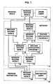
- Referring more particularly to FIG. 1, there is shown a generalblock diagram of a packet communications system including amessage originating location 10, a
transmission network 13 and amessage destination location 24. Message originating location 10comprises an originating message routing agent 12 and amessagerouting node 11. Originating agent 12 is a computer programwhich requests the use of thetransmission network 13 to transmita message to a destination agent 23 (another computer program ata remote location). Similarly,destination location 24 includesa message routing node E (22) and a messagerouting destinationagent 23. From the perspective of the message routing function,a message routing agent is any program that uses the messagerouting function. Normally, message routing agents such as 12and 23 comprise resource managers that provide many otherservices besides message routing, such as message queuing. - The packet communications system of FIG. 1 includes a pluralityof message routing nodes A-I interconnected by transmissionlinks. Thus, node A (11) is connected to nodes B (14) and G(15), node B is connected to nodes C (18) and E (22), node G isconnected to node H (16), node H is connected to nodes C (18) andI (21), and node I is connected to node E (22). The interconnections of the message routing nodes A through I is onlyillustrative and many more nodes could be included in the packetnetwork, interconnected by many other transmission links. Inaccordance with well known packet network technology, the messagerouting nodes A through I utilize information in the headers ofthe packets launched on the network to route the packet to theappropriate destination node. Message routing networks such as
network 13 are connectionless networks in which many messagesfrom many different origins may be flowing simultaneously on agiven connection between a pair of nodes. The function of thenode is to forward each of the messages, received from aconnected node, toward its ultimate destination. - One or more of the message routing nodes A through I of FIG. 1has associated therewith a routing agent program (RAP).
Routingagent program 17, for example, is associated with node H (16)while routingagent program 19 is associated with node C (18).In accordance with the present invention,RAPS network 13 toassist in determining the actual ultimate destination of theattached packet, using information found in the header of thepacket. The purpose of the routing agent programs is to permitthe selection of the message destination to be deferred until themessage is actually traversing the path to the destination node.Such routing flexibility is important for many real timeapplications such as: - Routing a message to an intermediate point for furtheraddress resolution, for example by invoking a directory toresolve a name into an address or to determine thedestination based on the data content (e.g., an "800" numberor a credit card number).
- Selecting an alternate destination in case of a failure ofthe primary destination node or system.
- Selecting a destination based on load balancingconsiderations.
- Performing transforms on the message data, possibly fortransmission on a particular medium.
- Logging and authentication of the message at gatewaysbetween different networks, possibly owned by differententerprises.
- In order to implement the universal, flexible deferred routingmechanism of the present invention, a Naming and AddressingParameter String (NAPS), consisting of one or more addresselements, is included in the header of each message launched onthe network. More particularly, the NAPS structure is used tospecify both the source address and the destination address inthe message header. The desired flexibility is implemented bythe interaction of these NAPS with the RAPS. More particularly,the RAPS can be used to:
- Edit the destination NAPS enroute to alter the ultimatedestination or even the next node in the route.
- Enhance the NAPS information by user-provided extensionssuch as user directory identifications or user securityverification identifications to determine if a messageshould be permitted to pass a given network gateway. Aparticular RAP address may, for example, be included in therouting simply to ensure the appropriate NAPS processing.
- Store lists of destinations to determine the path and theintermediate processing to be performed on the message (theNAPS or the data itself) enroute to the final destination.
- Control the node switching operation to determine when,where and how a particular message is to be switched fromone point to another.
- These functions will be described hereinafter.
- The NAPS can be formally defined as follows
- The notation of the above definition of the NAPS is used forexpository purposes only and does not represent the architecturalform of the NAPS. The parentheses delimit the NAPS components,a comma separates NAPS elements and brackets show that a elementis optional. The actual encoding of the NAPS is entirelyoptional and can, for example, be encoded using the ISO AbstractSyntax Notation One (ASN.1). In the above definition, definesa "message routing address" that consists of the followingthree-tuple:
- 〈naps-element〉
- specifies the destination node of themessage.
- (agent-name)
- identifies the agent that is to receive themessage at the destination node.
- 〈agent-parm〉
- parameters passed to the receiving, agentsuch as a directory name.
- The NAPS is defined recursively, permitting the specification ofa sequence of successive, intermediate locations for messageprocessing, yielding a very powerful naming and addressingfacility.
- In FIG. 2 there is shown a graphical representation of a packetmessage comprising a
packet header 30, and adata block 37associated withheader 30.Header 30, in turn, comprises aplurality of message routing addresses 34, 35, ..., 36, eachcomprising anode identification field 31, anagent name field 32and anagent parameter field 33. Most networking protocols allowone destination and one origin address per message. The messagerouting method and apparatus of the present invention, however, permit both the destination and the origin addresses to consistof an arbitrarily deep stack of address elements. Although eachNAPS element may consist of three components (NodeName, AgentNameand AgentParm), any of these components can be null, having theimplications to be discussed later. - Before proceeding to a more detailed description of theinvention, is first useful to discuss the naming conventionswhich might be used in specifying the node and agent names in theNAPS. Such nodes and agents may, for example, have global nameswhich are unique throughout the network in which they are used.To this end, such names can follow existing network namingconventions which are intended to be global. Many existingnetwork architectures, such as IBM's SNA, ARPA's TCP/IP and ISO'sX.400 E-mail, have an already-existing naming authority hierarchywhich allow network administrators to create globally uniquenames by registering company or business unit names and creatingnew names by appending subunit names to the registered name. Forexample, suppose a company is name "ABC, Inc." and the networkadministrator for the "DE" division of ABC, Inc. has registeredthe structured Network Identifier USABCxx with IBM as theregistration authority for SNA network identifiers and the ABC,Inc. corporate headquarters has allotted the network identifierUSABCDE for use by the DE division. Under the SNA naming rules,the DE division has the authority to create network qualifiednames of the form USABCDE.xxxxxxxx, where "xxxxxxxx" is a namethat obeys the rules for LU names. Not only can the user createglobally unique names for the SNA LUs, PUs and Control Points,but can also generate global names for their Message Routingresources using the form
- On the other hand, registration with Internet would allow thegeneration of global names of the form
- Logical links between any two MR nodes is called a "pipe." Pipescan be implemented using logical connections provided byexisting communications subsystems such as the SNA sessions, OSIassociations or TCP/IP connections. Each message of the formatof FIG. 2 may include a bit string representing the message classof the message. The message class specifies the routingproperties required for the message (e.g., SECURE or EXPEDITE)and acts as a filter to ensure that a chosen path satisfies therequirements of the message.
- The power of the message routing technology outlined in FIGS. 1and 2 lies in its ability to route messages even though theoriginator of the message does not know the identity of or thelocation of the ultimate recipient of the message. Thesecapabilities are implemented by the NAPS and the following threetables:
Local Agent Table AgentName Agent Process Access and status Destination Node Routing Table DestinationNodeName MessageClass Pipe Process Access and Status NAPS Edit Table Node Name Agent Name Action New Node Name NewAgent Name NewAgent Parameter - In TABLES 1, 2 and 3, the NodeName field has the form of a globalname as discussed above, and should nominally be the name of anexisting message routing node on the network. In reality, thisname can be anything and will be processed as discussed below inconnection with the routing algorithm of FIGS. 3 through 6. RealMR global names, however, should be unique among all of the nodesthat will send messages to this node. This is most easilyaccomplished by selecting a name that is globally unique acrossall node names around the world, as described above.
- The AgentName field also has the form of a global name and isnominally the name of an existing Message Routing agent, but in reality can be null or may represent a class or a set of agent,or anything else. This will likewise be explained in connectionwith the routing algorithm of FIG. 3. The AgentName must beunique among all of the agents that reside on that node.Moreover, agent names that represent classes or sets of agentsshould be unambiguous across all nodes where other agents mayreference the agent name. For example, the Passport Credit CardCompany may choose to deploy an agent name "Passport Authorize"for a set of credit card authorization applications distributedacross a set of networks. At the same time, the U.S. Customsserver might deploy the same agent name for an application thatauthorizes the renewal of passports. The network administratorsare responsible for ensuring that it is impossible for a messagesent to one of the applications to arrive at the other. The useof one of the above-described network architecture global namingstandards insures global uniqueness.
- TheAgentParm field is for the use of agents to pass smallamounts of data between themselves. The Routing Agent Programs(RAPs) can examine and even modify theAgentParm fields. Notethat only agents and RAPs constructed with each other in mind canutilize theAgentParm field and generic RAPs would not examine ormake use of the AgentParm field.
- The component of each Message Routing (MR) node that performsmessage routing is called the Routing Services (RS) component.Routing Services receives messages from three different sources:
- Application agents that are originating messages;
- Routing agents that are originating messages or reroutingmessages that they have intercepted in transit; and
- Pipes that have received messages from other MR nodes.
- RS processes each of the above messages in the same way,regardless of the message's source, as shown in the flowchart of FIG. 3.
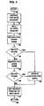
- Turning then to FIG. 3 of the drawings, the routing algorithmaccording to the present invention which is implemented in eachMR node of FIG. 1 begins in
start box 70 and entersbox 71 toreceive a message from a local or a remote Agent on the networksystem. The RS of FIG. 3 operates only on the top element of thedestination NAPS in the header of the message. Thedecision box 73 examines the NodeName field (TABLE 2) in this top element ofthe destination NAPS. This NodeName field can have one of fourvalues: - It can be null.
- It can be the name of this MR node.
- It can be the name of another MR node, somewhere else in thenetwork.
- It can be a pseudo node name, to be used as described below.
- If the value of the NodeName field is null (which it would be ifthe message were received from a local agent or local RoutingAgent Program (RAP), but which can never be the case if thismessage is received from a pipe), the RS assumes that the messageis destined from some agent or RAP on this node. As will bedescribed later, this may not be the case. If the NodeName fieldin the top element of the NAPS stack contains either the name ofthis node or is null,
decision box 73 assumes that thedestination agent is this node and goes todecision box 75 tosearch the Local Agent Table (TABLE 1 above). The Local AgentTable is a list of all agents and Routing Agent Programs (RAPS)that are actively running on this node. If an entry matching theagent name field is found,box 84 is entered where the message isqueued to the agent or RAP identified in the Local Agent Table.Box 85 is then entered to return an acknowledgment to thecalling program and the process of FIG. 3 terminated inbox 86.If the name is not found in the Local Agent Table, as determinedbydecision box 75, or if the agent name in the NAPS is null,box 76 is entered to attempt to edit the address element at the topof the NAPS. This editing process is described in detail inconnection with FIGS. 4 and 5. - If theNodeName field of the top element of the incoming messageNAPS contains the name of some other MR node, or contains thename of a pseudo node, as determined by
decision box 73,decisionbox 74 is entered to attempt to determine the identity of thepipe to be used to forward the message on its way to the namedidentification node. To this end, the DestinationNode Table(TABLE 2) is searched, using the combination of the NodeName intheNodeName field and the message class of the message. If asuitable pipe cannot be found, as determined bydecision box 78,box 76 is entered to attempt to edit the NAPS, as will bedescribed in connection with FIGS. 4 and 5. If the search fora suitable pipe succeeds, as determined bydecision box 78,box 80 is entered to queue the message for transmission on the pipeso identified.Box 81 is then entered to return an acknowledgmentto the calling program.Terminal box 86 is then entered toterminate the process of FIG. 3. - If
address editing box 76 is entered, due to a failure in thesearches in eitherbox box 76. If so,box 73 is re-entered to re-analyze thenewly edited NAPS. If no editing has taken place in the mostrecent attempt inbox 76, as determined by decision box 77,decision box 79 is entered to determine the type of error returnto be used, either synchronous or asynchronous. The program thatcalls the process of FIG. 3 specifies whether it wants asynchronous or an asynchronous error return. A synchronousreturn returns control to the caller with an error return code inbox 82. An asynchronous return queues the message to a specialagent called the "Error Handler" inbox 83. The error handler,in turn, sends a negative acknowledgment to the sender at theorigin node. Note thatbox 85 is then entered to return an OK to the RS caller because responsibility for the message has beentransferred to the error handler and the caller need not react.In either event, the process of FIG. 3 terminates interminal box 86. - The editing function of
box 76 of FIG. 3 can be simple or verysophisticated. While a simple editor will be described inconnection with FIGS. 4 and 5, it is clear that much more complexeditors can be used as required by the various users of thenetwork. As a minimum, however, such an editor must at least beable to pop a NAPS element off of the destination address stackwhen it is no longer needed, must be able to add a new NAPSelement onto the destination address stack to provide new routinginformation and yet preserving the existing routing informationfor processing at another routing point along the message path,and must be able to replace one or more NAPS element fields tocorrect or amend the required information. Such an editor isshown in FIGS. 4 and 5. - Referring then to FIG. 4, there is shown a flow chart of a NAPSeditor which is table-driven by a table such as that shown inTABLE 3. The flow chart of FIG. 4 does the table look-upsnecessary to control the editor functions while FIG. 5 is a flowchart of the process for actually performing the edits. The flowchart of FIG. 4 starts in
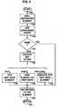
start box 90 wherebox 91 is entered tounpack the fields from the top NAPS element of the destinationaddress. The return pointer is then initiated to null, thereturn value used when the edit attempt is unsuccessful.Box 93is then entered to search the edit table (TABLE 3 above), usingthe NodeName and AgentName values from the NAPS as the initialsearch keys. The NodeName portion of the search key is firstheld constant while the AgentName portion is searched inbox 93,increasingly generalized by successively substitutingincreasingly more general wildcard values until either a matchingentry is found or until all wildcards have been used, asdetermined bydecision box 94. This procedure assumes that theAgentName is a sequence of sub-strings separated by periods,i.e., a global name in one of the standard global formats described above. If a match is found,box 99 is entered toupdate the destination NAPS. If no match is made with theAgentName field, as determined bydecision box 94,box 95 isentered where the NodeName field is searched in the edit table.The search inbox 95 is also increasingly generalized bysuccessively substituting increasingly more general wildcardvalues until either a matching entry is found or until allwildcards have been used, as determined bydecision box 96. Ateach level of search inbox 95, the AgentName value is reset tothe original value. If an edit table entry is found bydecisionbox 96,box 99 is entered to update the destination NAPS, as willbe discussed in connection with FIG. 5. If the destination NAPSis updated inbox 99,box 97 is entered to set the return pointerto the new NAPS produced inbox 99. The process of FIG. 4terminates inbox 98. Note that, if no NAPS editing takes placedue to the failure to find an edit table entry, the initializednull returned pointed is returned, signaling a routing error. - The destination NAPS updating procedure of
box 99 in FIG. 4is shown in detail in FIG. 5. Referring to FIG. 5, there isshown a flow chart of the destination NAPS updating procedurereferred to in connection withbox 99 of FIG. 4. Starting instart box 100,box 101 is entered to initialize the returndestination element to a null value.Box 102 is then entered totest the NewNodeName and NewAgentName values obtained from theEdit Table (TABLE 3) in the process of FIG. 4 are compared to theNodeName and AgentName values in the top NAPS element of themessage header. This test prevents infinite recycling of theeditor due to errors in the edit table. If these values are thesame,box 105 is entered to return the null values (initializedin box 101) to the calling program, indicating a edit failure. - If the edit table values of NewNodeName and NewAgentName aredifferent from the values in the top NAPS element, as determinedby
decision box 103,box 104 is entered to execute the editaction specified in the edit table. As shown in FIG.5, theseedit actions include at least pop, push and replace the topelement of the NAPS. Other editing actions are, of course, possible and will be obvious to those skilled in the art. Theseediting actions are under control of the edit table and can bespecified by the network administrator, by the source user or bythe destination user of the network. - If a pop editing action is specified in the edit table,
box 108 is entered where the top element in the NAPS stack is poppedoff of the stack and the return pointer is set to the new topelement. If there are no more NAPS components in the stack, themessage is considered undeliverable and a null pointer is set inbox 105, indicating an edit failure. If a new NAPS element isconstructed from the values in the NewNodeName, NewAgentName andNewAgentParm fields of the NAPS edit table entry,box 105 isentered where that new NAPS element is pushed onto the NAPS stackin the header of the message. These new NAPS element fieldvalues can be null or a control character used to replicate theprevious value in that field. The return pointer is set inbox 105 to point to the newly pushed NAPS element. If one or morefields of the top NAPS element are to be replaced,box 109 isentered where the desired NAPS elements fields are replaced. Asbefore, a null value or a replacement symbol can be used as thereplacement value for any field value. Again, the return pointeris set inbox 105 to reference the top NAPS element. The processof FIG. 5 terminates inreturn box 107. - The operation of the NAPS editing function in the RAPs of thepresent invention will be illustrated in detail in connectionwith the packet communications system of FIG. 6. The system ofFIG. 6 is for a credit card authorization application between aplurality of
retailer networks bank networks credit card network 124.Message routing nodes node 133,also as inter-network connection nodes shared by the two networkson which they appear. It is to be understood that each ofnetworks source user 120, for example apoint-of-sale (POS) terminal in a retail establishment, issues amessage requesting a charge authorization from the bank which hasissued the customer's credit card. This request message isdelivered to thebank destination user 132 which returns anauthorization (or denial) of credit message back to thesourceuser 120. - Beginning at
source user 120, when a customer charges apurchase at a retail establishment, the clerk at thepoint-of-sale (POS) terminal pulls the credit card through thecard reader and the point-of-sale terminal creates anauthorization message to be sent acrossnetwork 122. Thismessage will, of course, eventually arrive at an IMS applicationin a mainframe computer owned by the bank owning thebank network 130. The point-of-sale terminal is called an MR client node,indicating that the POS terminal knows nothing about routingmessages, but relies on theadjacent MR node 121 to provide thisfunction. For specificity, it is assumed that the global nodename of the POS terminal is (SNA, USSEERAW.POS234X1). Themessage constructed by the POS terminal is as follows, omittingdetails not related to this example:
- When this message is passed to
entry node 121,node 121 firstexamines the NodeName field of the top element of the destination NAPS (box 73, FIG. 3). As can be seen above, this field is nulland thereforenode 121 looks in the Local Active Agent Table foran active agent or Routing Agent Program with the name(IP,Authorize.Passport.com). Since there will be no entry tomatch this agent name, the message will be submitted for NAPSediting (box 76, FIG. 3). The destination NAPS edit processpushes a new element onto the destination NAPS that contains thenode name "(SNA,USSEERAW.AWSRV193)," the global name ofroutingserver node 133 inside ofnetwork 122 and which is enroute tomessage routing node 123. When the editing is done, the messageappears as follows:
- The internal
message routing node 133 withinnetwork 122 willalso try to route this message. When the destination node namefield is examined (box 73, FIG. 3), the destination node will bethis node ("ON_ME,"box 73, FIG. 3)(node 133) and the agent namefield will be examined. As noted above, the agent name fieldcontains "null."Node 133 therefore attempts to edit the top NAPSelement, as shown in flow chart of FIG. 3. The edit table innode 133 is consulted and the following entry is found:Edit Table Node Name Agent Name Action New Node Name NewAgent Name (SNA,USSEERAW.AWSRV193) null Pop null null - This entry causes the top element of the NAPS to be poppedand discarded (
box 108, FIG. 5), exposing the next NAPS element.This next element is, of course, the original NAPS elementattached to the message.Routing node 133 will now try to routethe message according to the new NAPS element ("YES" in box 77,FIG. 3). Since the node name field of the new NAPS is still"null," therouting node 133 searches the agent table (box 75 inFIG. 3) for the agent or Routing Agent Program (RAP) with thedesignation (IP,Authorize.Passport.com). Since no such entryexists, the NAPS will be submitted to the editor for editing. Anedit table entry is found as follows:Edit Table Node Name Agent Name Action New Node Name NewAgent Name null (IP, Authorize.-Passport.com) Push (IP, GWSEERS9.-Passport.com) (IP, Gateway.-Passport.com) - This entry causes a new NAPS element to be pushed onto theNAPS stack with the noted field values. The message header willthen look as follows:


- When
MRN 133 tries to reroute this message, it will see thatthe message is destined for a different node, and will thereforeconsult its Destination Node Routing Table (TABLE 2 above). TheDestination Node Table, in turn, will identify the pipe to thenext adjacent node and queue the message for that node. The nextnode may or may not be (IP,GWSEERS9.Passport.com). If not, theRouting Services (RS) at that node will also see that the messageis destined for another node, will consult its Destination NodeTable and queue the message to the pipe specified in that table,transporting the message to the next adjacent node via the pipe.These steps will be repeated until the message finally arrives atnode 123, identified as (IP,GWSEERS9.Passport.com), which is thegateway between theretailer network 122 and the creditcardbackbone network 124. - At
node 123, the RS detects that the message is destined forthis node and attempts to route the message to an agent or RAPwith the name (IP,Gateway.Passport.com). This time, it findsthat a RAP with that name exists and is active, and queues themessage to that RAP. When the message is delivered to the RAPidentified as "(IP,Gateway.Passport.com)," the RAP, will firstpop the top element off of the destination NAPS stack, so themessage will once again look like it did when it was firstcreated. This RAP will then examine the AgentParm field of thenew top NAPS element to determine the credit card number. Usinga translation algorithm proprietary to the credit card company,the credit card number is translated to the name of the bankowning the credit card account. In this case, the bank operatingbank network 130 is the bank owning the credit card account. Theediting facilities at this RAP will then push a new destinationelement onto the destination NAPS stack, and will push a newsource element onto the source NAPS stack, resulting in a messagelooking as follows:
- The new element on the destination NAPS stack will route themessage to a RAP on a gateway node owned by BANC-TWO, e.g.,
node 125. The new element on the origin NAPS stack will assist therouting of the return message. When the routing nodes innetwork 124 attempt to reroute the message, they will now see that themessage is destined for another node. By consulting theirDestination Node Routing Tables, these nodes will determine whichpipes to queue the message for transport to the next node on theroute. Eventually, the message will be received atnode 125,identified as (IP,GWPassport3.Banc-Two.com) in the destinationNAPS. - When the message reaches
node 125, the Routing Services will route the message to the RAP named "(IP,Gateway.Banc-Two.com)."This RAP will pop the top element off of the destination NAPSstack and examine the element underneath. It will then note thatthe original AgentName field has requested a credit authorizationtransaction. The AgentParm field, moreover, is then examined toconfirm that the bank requested is the Banc-Two, again bytranslating the credit card number. It can be assumed thatBanc-Two has decentralized its operation and includes a number ofdifferent credit card databases. It is therefore necessary forthe RAP to determine to which computer database to route themessage. The RAP will then modify the remaining element of theNAPS stack, and push yet another element onto the origin NAPSstack so that the message now looks as follows:
- When a routing node within
network 130 attempts to route thismessage, it will see that the message is destined for a differentnode. Consulting its Destination Node Routing Table, it will forward the message according to the pipes found in this table.The message will thereby be forwarded acrossnetwork 130 until itreachesnode 131, identified as (SNA,USBTWOAW.REGION12). Atnode 131, the message will be routed to thedestination user 132,identified in the message as (UNDEF,CCAUTH). Theuser agent 132is responsible for authorizing all credit card transactions fromall of the credit card retailers with which BANC-TWO isassociated.User agent 132 will perform the requestedauthorization and build a return message to be sent back to theoriginating point-of-sale (POS) terminal. In this process, thedestination NAPS stack of the incoming message is moved to theorigin NAPS stack of the return message, the origin NAPS stack ofthe incoming message is moved to the destination NAPS stack ofthe return message, and the response is placed in the AgentParmfield of the deepest element in the resulting destination NAPSstack. The return message will look like this:
- This message is launched to
node 131 where the RoutingProgram will examine the NodeName field and, seeing that the message is for another node with consults its Destination NodeRouting Table and queue the message for the appropriate pipe.The message will make its way across the bank'snetwork 130 untilit reachesnode 125, identified as (IP,GWPassport3.Ban-Two.com).At this node the message is submitted for NAPS editing (since theAgentName is null) and an appropriate entry in the Edit Tablewill cause the top entry to be popped off of the Destination NAPSstack. The message is then routed across thecredit card network 124 tonode 123, identified as (IP,GWSEERS9.Passport.com). Atnode 123, the message is again submitted for NAPS editing and, inresponse to an appropriate entry in the NAPS edit table, thisentry will be popped off of the destination NAPS stack to exposethe bottom NAPS entry. Using this destination, the message isthen routed across theretailer network 122, throughnode 133, tothenode 121, identified as (SNA,USSEERAW.POS234X1). The messageis then routed to the point-of-sale user 120, identified as(SNA,USSEERAW.CCTRANS), where the message in the AgentParm fieldwill be displayed to the retail clerk. - It can be seen that the example described in connection withFIG. 6 utilizes NAPS stacks to represent both the origin addressand the destination address for user messages to be routed acrossa plurality of different packet communications networks. Routingprograms at intermediate nodes in the different networks edit theNAPS elements to ensure the forwarding of the message to theappropriate destination even when the originating station doesnot know the address of the ultimate destination. A non-addressfield (AgentParm) is included in the NAPS element to assist inboth routing and processing of the message.


Claims (7)
- A method for routing messages through packetcommunications networks from an originating station onsaid networks to a destination station on said networks,said method comprising the steps of:defining origin and destination addresses with a stack ofmulti-element address specifications,editing, at at least one intermediate node in saidnetworks, said stacked multi-element addressspecifications,each of said multi-element address specifications performing the stepsof:identifying a node on one of said network,identifying a user agent on said networks; and,specifying arbitrary parameters to said agents on saidnetworks.
- The method according to claim 1 wherein said step ofediting further comprises the step of
popping one of said multi-element address specificationsoff of one of said stacks. - The message routing system according to claim 1 or 2wherein said step of editing further comprises the stepof
pushing a new multi-element address specification ontoone of said stacks. - The method according to anyone of claim 1 to 3 whereinsaid step of editing further comprises the step ofaltering at least one element of said multi-elementaddress specification.
- The method according to anyone of claim 1 to 4 whereinsaid step of editing further comprises the steps ofspecifying, in an edit table, the editing action to betaken for particular multi-element addressspecifications.
- The method according to anyone of claim 1 to 5 furthercomprising the steps of at each said at least one node,determining if said at least one node is the destinationfor a message on said networks,
specifying, in a destination node routing table, theroute to the next node in a route to a destination nodefor use when said at least one node is not thedestination of said message, and
specifying, in a user specifying table, the user on thecurrent node when said at least one node is thedestination of said message. - A message routing system for packet communicationsnetworks for routing messages across said networks froman originating station on said networks to a destinationstation on said networks, said routing system comprising
means implementing each of the steps of the method ofclaims 1 to 6.
Applications Claiming Priority (2)
| Application Number | Priority Date | Filing Date | Title |
|---|---|---|---|
| US08/369,051US5563878A (en) | 1995-01-05 | 1995-01-05 | Transaction message routing in digital communication networks |
| US369051 | 1995-01-05 |
Publications (3)
| Publication Number | Publication Date |
|---|---|
| EP0725523A2 EP0725523A2 (en) | 1996-08-07 |
| EP0725523A3 EP0725523A3 (en) | 1997-08-06 |
| EP0725523B1true EP0725523B1 (en) | 2003-07-23 |
Family
ID=23453883
Family Applications (1)
| Application Number | Title | Priority Date | Filing Date |
|---|---|---|---|
| EP95480177AExpired - LifetimeEP0725523B1 (en) | 1995-01-05 | 1995-12-06 | Transaction message routing in digital communications networks |
Country Status (4)
| Country | Link |
|---|---|
| US (2) | US5563878A (en) |
| EP (1) | EP0725523B1 (en) |
| JP (1) | JP3229183B2 (en) |
| DE (1) | DE69531337T2 (en) |
Cited By (6)
| Publication number | Priority date | Publication date | Assignee | Title |
|---|---|---|---|---|
| US7469292B2 (en) | 2004-02-11 | 2008-12-23 | Aol Llc | Managing electronic messages using contact information |
| US7590695B2 (en) | 2003-05-09 | 2009-09-15 | Aol Llc | Managing electronic messages |
| US7627635B1 (en) | 2003-07-28 | 2009-12-01 | Aol Llc | Managing self-addressed electronic messages |
| US7647381B2 (en) | 2005-04-04 | 2010-01-12 | Aol Llc | Federated challenge credit system |
| US7650383B2 (en) | 2005-03-15 | 2010-01-19 | Aol Llc | Electronic message system with federation of trusted senders |
| US7882360B2 (en) | 2003-12-19 | 2011-02-01 | Aol Inc. | Community messaging lists for authorization to deliver electronic messages |
Families Citing this family (105)
| Publication number | Priority date | Publication date | Assignee | Title |
|---|---|---|---|---|
| US5563878A (en)* | 1995-01-05 | 1996-10-08 | International Business Machines Corporation | Transaction message routing in digital communication networks |
| US7369650B1 (en) | 1995-05-16 | 2008-05-06 | At&T Corp. | Service and information management system for a telecommunications network |
| US5729597A (en)* | 1995-05-16 | 1998-03-17 | At&T Corp | Service and information management system for a telecommunications network |
| US5742845A (en) | 1995-06-22 | 1998-04-21 | Datascape, Inc. | System for extending present open network communication protocols to communicate with non-standard I/O devices directly coupled to an open network |
| US5699522A (en)* | 1996-02-23 | 1997-12-16 | Unisys Corporation | Data processing system with fast message processing for upgraded input/output stations |
| US5742611A (en)* | 1996-03-18 | 1998-04-21 | Neo-Core, Llc | Client server network and method of operation |
| US7167924B1 (en)* | 1996-06-10 | 2007-01-23 | Diebold, Incorporated | Financial transaction processing system and method |
| GB9617553D0 (en)* | 1996-08-21 | 1996-10-02 | Walker Christopher P H | Communication system with improved routing switch |
| GB9720152D0 (en) | 1996-12-18 | 1997-11-26 | Mayup Limited | Communications system and method |
| TW359054B (en)* | 1996-12-20 | 1999-05-21 | Sony Corp | Method and apparatus for automatic sending of e-mail and automatic sending control program supplying medium |
| TW401548B (en) | 1996-12-20 | 2000-08-11 | Sony Corp | Method and apparatus for sending E-mail, method and apparatus for receiving E-mail, sending program supplying medium, receiving program supplying medium |
| US5781739A (en)* | 1996-12-31 | 1998-07-14 | International Business Machines Corp. | IMS/WWW mapping system |
| US5978845A (en)* | 1997-03-25 | 1999-11-02 | Sun Microsystems, Inc. | Network management relay mechanism |
| US7412533B1 (en) | 1997-03-31 | 2008-08-12 | West Corporation | Providing a presentation on a network having a plurality of synchronized media types |
| AU6882998A (en)* | 1997-03-31 | 1998-10-22 | Broadband Associates | Method and system for providing a presentation on a network |
| US7143177B1 (en) | 1997-03-31 | 2006-11-28 | West Corporation | Providing a presentation on a network having a plurality of synchronized media types |
| US7490169B1 (en) | 1997-03-31 | 2009-02-10 | West Corporation | Providing a presentation on a network having a plurality of synchronized media types |
| US6430286B1 (en)* | 1997-04-22 | 2002-08-06 | At&T Corp | Service and information management system for a telecommunications network |
| US6088356A (en)* | 1997-06-30 | 2000-07-11 | Sun Microsystems, Inc. | System and method for a multi-layer network element |
| US6021132A (en)* | 1997-06-30 | 2000-02-01 | Sun Microsystems, Inc. | Shared memory management in a switched network element |
| US6049528A (en)* | 1997-06-30 | 2000-04-11 | Sun Microsystems, Inc. | Trunking ethernet-compatible networks |
| US6016310A (en)* | 1997-06-30 | 2000-01-18 | Sun Microsystems, Inc. | Trunking support in a high performance network device |
| US6044418A (en)* | 1997-06-30 | 2000-03-28 | Sun Microsystems, Inc. | Method and apparatus for dynamically resizing queues utilizing programmable partition pointers |
| US6044087A (en)* | 1997-06-30 | 2000-03-28 | Sun Microsystems, Inc. | Interface for a highly integrated ethernet network element |
| US6081522A (en)* | 1997-06-30 | 2000-06-27 | Sun Microsystems, Inc. | System and method for a multi-layer network element |
| US6115378A (en)* | 1997-06-30 | 2000-09-05 | Sun Microsystems, Inc. | Multi-layer distributed network element |
| US6094435A (en)* | 1997-06-30 | 2000-07-25 | Sun Microsystems, Inc. | System and method for a quality of service in a multi-layer network element |
| US6081512A (en)* | 1997-06-30 | 2000-06-27 | Sun Microsystems, Inc. | Spanning tree support in a high performance network device |
| US6246680B1 (en) | 1997-06-30 | 2001-06-12 | Sun Microsystems, Inc. | Highly integrated multi-layer switch element architecture |
| US6199102B1 (en) | 1997-08-26 | 2001-03-06 | Christopher Alan Cobb | Method and system for filtering electronic messages |
| US6128622A (en)* | 1997-11-26 | 2000-10-03 | International Business Machines Corporation | IMS web studio taskguide |
| US6119171A (en)* | 1998-01-29 | 2000-09-12 | Ip Dynamics, Inc. | Domain name routing |
| US6128611A (en)* | 1998-04-30 | 2000-10-03 | International Business Machines Corporation | Internet-enabled generic application program for accessing hierarchical data |
| JP3490294B2 (en)* | 1998-06-24 | 2004-01-26 | インターナショナル・ビジネス・マシーンズ・コーポレーション | Message multicast method and computer |
| US6430571B1 (en) | 1998-07-16 | 2002-08-06 | International Business Machines Corporation | Multi-frame output form that facilitates internet search and update in a hierarchical database |
| US6112227A (en) | 1998-08-06 | 2000-08-29 | Heiner; Jeffrey Nelson | Filter-in method for reducing junk e-mail |
| US5991300A (en)* | 1998-09-08 | 1999-11-23 | Cisco Technology, Inc. | Technique for efficiently performing optional TTL propagation during label imposition |
| US6567915B1 (en)* | 1998-10-23 | 2003-05-20 | Microsoft Corporation | Integrated circuit card with identity authentication table and authorization tables defining access rights based on Boolean expressions of authenticated identities |
| US6668284B1 (en)* | 1998-11-04 | 2003-12-23 | Beckman Coulter, Inc. | Software messaging system |
| US20020169820A1 (en) | 1998-11-20 | 2002-11-14 | Eugene Sayan | Process pool methods and apparatus |
| US7171000B1 (en) | 1999-06-10 | 2007-01-30 | Message Secure Corp. | Simplified addressing for private communications |
| US6757740B1 (en) | 1999-05-03 | 2004-06-29 | Digital Envoy, Inc. | Systems and methods for determining collecting and using geographic locations of internet users |
| US7685311B2 (en)* | 1999-05-03 | 2010-03-23 | Digital Envoy, Inc. | Geo-intelligent traffic reporter |
| US7844729B1 (en) | 1999-05-03 | 2010-11-30 | Digital Envoy, Inc. | Geo-intelligent traffic manager |
| US20020019932A1 (en)* | 1999-06-10 | 2002-02-14 | Eng-Whatt Toh | Cryptographically secure network |
| US20020101998A1 (en)* | 1999-06-10 | 2002-08-01 | Chee-Hong Wong | Fast escrow delivery |
| US6988199B2 (en) | 2000-07-07 | 2006-01-17 | Message Secure | Secure and reliable document delivery |
| US7421395B1 (en)* | 2000-02-18 | 2008-09-02 | Microsoft Corporation | System and method for producing unique account names |
| US8463839B2 (en) | 2000-03-28 | 2013-06-11 | Cybernet Systems Corporation | Distributed computing environment |
| US6684250B2 (en)* | 2000-04-03 | 2004-01-27 | Quova, Inc. | Method and apparatus for estimating a geographic location of a networked entity |
| US7075926B2 (en)* | 2000-05-24 | 2006-07-11 | Alcatel Internetworking, Inc. (Pe) | Programmable packet processor with flow resolution logic |
| US6870849B1 (en)* | 2000-07-06 | 2005-03-22 | Ross W. Callon | Apparatus and method for efficient hashing in networks |
| US7251728B2 (en) | 2000-07-07 | 2007-07-31 | Message Secure Corporation | Secure and reliable document delivery using routing lists |
| JP3543952B2 (en) | 2000-07-21 | 2004-07-21 | 日本電気株式会社 | MPLS packet transfer method and packet switch |
| US6968359B1 (en) | 2000-08-14 | 2005-11-22 | International Business Machines Corporation | Merge protocol for clustered computer system |
| US6996631B1 (en) | 2000-08-17 | 2006-02-07 | International Business Machines Corporation | System having a single IP address associated with communication protocol stacks in a cluster of processing systems |
| US7120697B2 (en)* | 2001-05-22 | 2006-10-10 | International Business Machines Corporation | Methods, systems and computer program products for port assignments of multiple application instances using the same source IP address |
| US6941384B1 (en) | 2000-08-17 | 2005-09-06 | International Business Machines Corporation | Methods, systems and computer program products for failure recovery for routed virtual internet protocol addresses |
| US6996617B1 (en) | 2000-08-17 | 2006-02-07 | International Business Machines Corporation | Methods, systems and computer program products for non-disruptively transferring a virtual internet protocol address between communication protocol stacks |
| US6954784B2 (en)* | 2000-08-17 | 2005-10-11 | International Business Machines Corporation | Systems, method and computer program products for cluster workload distribution without preconfigured port identification by utilizing a port of multiple ports associated with a single IP address |
| US7089294B1 (en) | 2000-08-24 | 2006-08-08 | International Business Machines Corporation | Methods, systems and computer program products for server based type of service classification of a communication request |
| US7290028B2 (en)* | 2000-08-24 | 2007-10-30 | International Business Machines Corporation | Methods, systems and computer program products for providing transactional quality of service |
| US20020048372A1 (en)* | 2000-10-19 | 2002-04-25 | Eng-Whatt Toh | Universal signature object for digital data |
| US6965930B1 (en) | 2000-10-20 | 2005-11-15 | International Business Machines Corporation | Methods, systems and computer program products for workload distribution based on end-to-end quality of service |
| US6963917B1 (en) | 2000-10-20 | 2005-11-08 | International Business Machines Corporation | Methods, systems and computer program products for policy based distribution of workload to subsets of potential servers |
| US20040034715A1 (en)* | 2000-12-06 | 2004-02-19 | Steven Dawson | Content based routing devices and methods |
| JP2002175274A (en)* | 2000-12-06 | 2002-06-21 | Sony Corp | Information processing device and information processing method, network system, storage medium, and computer program |
| US7769844B2 (en)* | 2000-12-07 | 2010-08-03 | International Business Machines Corporation | Peer protocol status query in clustered computer system |
| US20020143954A1 (en)* | 2001-04-03 | 2002-10-03 | Aiken John Andrew | Methods, systems and computer program products for content-based routing via active TCP connection transfer |
| US20020152307A1 (en)* | 2001-04-12 | 2002-10-17 | Doyle Ronald Patrick | Methods, systems and computer program products for distribution of requests based on application layer information |
| US6801531B1 (en)* | 2001-04-24 | 2004-10-05 | Atitania Ltd. | Distributed processing system and method |
| US7035271B1 (en) | 2001-04-24 | 2006-04-25 | Atitania Ltd. | Method and apparatus for generating unique ID packets in a distributed processing system |
| US7099350B2 (en)* | 2001-04-24 | 2006-08-29 | Atitania, Ltd. | Method and apparatus for converting data between two dissimilar systems |
| US6975595B2 (en)* | 2001-04-24 | 2005-12-13 | Atttania Ltd. | Method and apparatus for monitoring and logging the operation of a distributed processing system |
| US6950437B2 (en)* | 2001-04-24 | 2005-09-27 | Atitania Ltd. | System and method for transmission of information between locations on a computer network with the use of unique packets |
| US20020164992A1 (en)* | 2001-05-07 | 2002-11-07 | Olsen James J. | Method and apparatus for data-dependant mobile network routing |
| US7711831B2 (en)* | 2001-05-22 | 2010-05-04 | International Business Machines Corporation | Methods, systems and computer program products for source address selection |
| US6832260B2 (en) | 2001-07-26 | 2004-12-14 | International Business Machines Corporation | Methods, systems and computer program products for kernel based transaction processing |
| US7231461B2 (en)* | 2001-09-14 | 2007-06-12 | International Business Machines Corporation | Synchronization of group state data when rejoining a member to a primary-backup group in a clustered computer system |
| US7937471B2 (en)* | 2002-06-03 | 2011-05-03 | Inpro Network Facility, Llc | Creating a public identity for an entity on a network |
| US7516182B2 (en) | 2002-06-18 | 2009-04-07 | Aol Llc | Practical techniques for reducing unsolicited electronic messages by identifying sender's addresses |
| US20040008688A1 (en)* | 2002-07-11 | 2004-01-15 | Hitachi, Ltd. | Business method and apparatus for path configuration in networks |
| US7215640B2 (en)* | 2002-07-11 | 2007-05-08 | Hitachi, Ltd. | Method and apparatus for path configuration in networks |
| US7139828B2 (en)* | 2002-08-30 | 2006-11-21 | Ip Dynamics, Inc. | Accessing an entity inside a private network |
| US8234358B2 (en) | 2002-08-30 | 2012-07-31 | Inpro Network Facility, Llc | Communicating with an entity inside a private network using an existing connection to initiate communication |
| EP1592182A4 (en)* | 2003-02-03 | 2010-05-12 | Nippon Telegraph & Telephone | Data transmission device and data transmission system |
| US7949785B2 (en)* | 2003-03-31 | 2011-05-24 | Inpro Network Facility, Llc | Secure virtual community network system |
| US7290033B1 (en) | 2003-04-18 | 2007-10-30 | America Online, Inc. | Sorting electronic messages using attributes of the sender address |
| US7562145B2 (en)* | 2003-08-28 | 2009-07-14 | International Business Machines Corporation | Application instance level workload distribution affinities |
| US7685279B2 (en)* | 2004-03-04 | 2010-03-23 | Quova, Inc. | Geo-location and geo-compliance utilizing a client agent |
| US8693323B1 (en) | 2004-04-05 | 2014-04-08 | Verizon Business Global Llc | System and method for managing communications in an access network |
| US7471669B1 (en)* | 2004-09-30 | 2008-12-30 | Nortel Networks Limited | Routing of protocol data units within a communication network |
| US7917396B1 (en) | 2005-02-15 | 2011-03-29 | Embarq Holdings Company, Llc | Method and system for processing communications orders |
| US20070064726A1 (en)* | 2005-09-21 | 2007-03-22 | Harris Corporation | Endpoint transparent independent messaging scheme system and method |
| US8219329B2 (en)* | 2006-05-26 | 2012-07-10 | Horiba Stec, Co., Ltd. | Thermal type mass flow meter, and thermal type mass flow control device |
| US8584199B1 (en) | 2006-10-17 | 2013-11-12 | A10 Networks, Inc. | System and method to apply a packet routing policy to an application session |
| US8312507B2 (en) | 2006-10-17 | 2012-11-13 | A10 Networks, Inc. | System and method to apply network traffic policy to an application session |
| US8046492B1 (en)* | 2007-11-06 | 2011-10-25 | Juniper Networks, Inc. | Offset independent filtering |
| US8443107B2 (en) | 2009-11-11 | 2013-05-14 | Digital Envoy, Inc. | Method, computer program product and electronic device for hyper-local geo-targeting |
| US9118618B2 (en) | 2012-03-29 | 2015-08-25 | A10 Networks, Inc. | Hardware-based packet editor |
| US9338225B2 (en) | 2012-12-06 | 2016-05-10 | A10 Networks, Inc. | Forwarding policies on a virtual service network |
| US9992107B2 (en) | 2013-03-15 | 2018-06-05 | A10 Networks, Inc. | Processing data packets using a policy based network path |
| WO2014179753A2 (en) | 2013-05-03 | 2014-11-06 | A10 Networks, Inc. | Facilitating secure network traffic by an application delivery controller |
| US9942152B2 (en) | 2014-03-25 | 2018-04-10 | A10 Networks, Inc. | Forwarding data packets using a service-based forwarding policy |
| US10268467B2 (en) | 2014-11-11 | 2019-04-23 | A10 Networks, Inc. | Policy-driven management of application traffic for providing services to cloud-based applications |
Family Cites Families (25)
| Publication number | Priority date | Publication date | Assignee | Title |
|---|---|---|---|---|
| US4423414A (en)* | 1981-08-27 | 1983-12-27 | Burroughs Corporation | System and method for name-lookup in a local area network data communication system |
| US4677588A (en)* | 1983-11-14 | 1987-06-30 | International Business Machines Corp. | Network interconnection without integration |
| US4718005A (en)* | 1984-05-03 | 1988-01-05 | International Business Machines Corporation | Distributed control of alias name usage in networks |
| US5133053A (en)* | 1987-02-13 | 1992-07-21 | International Business Machines Corporation | Interprocess communication queue location transparency |
| AU1199888A (en)* | 1987-03-13 | 1988-09-15 | Northern Telecom Limited | Communications system and components and methods for use therein |
| US5105424A (en)* | 1988-06-02 | 1992-04-14 | California Institute Of Technology | Inter-computer message routing system with each computer having separate routinng automata for each dimension of the network |
| US5025491A (en)* | 1988-06-23 | 1991-06-18 | The Mitre Corporation | Dynamic address binding in communication networks |
| US4873517A (en)* | 1988-06-23 | 1989-10-10 | International Business Machines Corporation | Method for selecting least weight end node to end node route in a data communications network |
| US4931941A (en)* | 1988-07-25 | 1990-06-05 | Bell Communications Research, Inc. | Adaptive routing of network traffic |
| US5383179A (en)* | 1988-12-15 | 1995-01-17 | Laboratoire Europeen De Recherches Electroniques Avancees | Message routing method in a system having several different transmission channels |
| US5142622A (en)* | 1989-01-31 | 1992-08-25 | International Business Machines Corporation | System for interconnecting applications across different networks of data processing systems by mapping protocols across different network domains |
| US5086428A (en)* | 1989-06-09 | 1992-02-04 | Digital Equipment Corporation | Reliable broadcast of information in a wide area network |
| US5095480A (en)* | 1989-06-16 | 1992-03-10 | Fenner Peter R | Message routing system for shared communication media networks |
| US5206856A (en)* | 1989-12-27 | 1993-04-27 | Bell Communications Research, Inc. | Routing of network traffic |
| US5166931A (en)* | 1990-09-04 | 1992-11-24 | At&T Bell Laboratories | Communications network dynamic addressing arrangement |
| FR2681164A1 (en)* | 1991-09-06 | 1993-03-12 | Thomson Csf | Process for routing a data packet within a digital transmission network |
| US5309433A (en)* | 1992-06-18 | 1994-05-03 | International Business Machines Corp. | Methods and apparatus for routing packets in packet transmission networks |
| US5262906A (en)* | 1992-06-19 | 1993-11-16 | Alcatel Network Systems, Inc. | Message routing for SONET telecommunications maintenance network |
| GB2268374A (en)* | 1992-06-23 | 1994-01-05 | Ibm | Network addressing |
| US5398012A (en)* | 1992-11-24 | 1995-03-14 | International Business Machines Corporation | Distributed processing of route selection across networks and subnetworks |
| JPH06318951A (en)* | 1993-01-07 | 1994-11-15 | Toshiba Corp | Cell transfer method and cell transfer system |
| EP0608653A1 (en)* | 1993-01-26 | 1994-08-03 | International Business Machines Corporation | Method and system for routing information between nodes in a communication network |
| US5353283A (en)* | 1993-05-28 | 1994-10-04 | Bell Communications Research, Inc. | General internet method for routing packets in a communications network |
| EP0627835B1 (en)* | 1993-06-03 | 2001-08-29 | International Business Machines Corporation | Improved network layer packet structure |
| US5563878A (en)* | 1995-01-05 | 1996-10-08 | International Business Machines Corporation | Transaction message routing in digital communication networks |
- 1995
- 1995-01-05USUS08/369,051patent/US5563878A/ennot_activeExpired - Fee Related
- 1995-12-06DEDE69531337Tpatent/DE69531337T2/ennot_activeExpired - Fee Related
- 1995-12-06EPEP95480177Apatent/EP0725523B1/ennot_activeExpired - Lifetime
- 1995-12-25JPJP33758695Apatent/JP3229183B2/ennot_activeExpired - Fee Related
- 1996
- 1996-05-29USUS08/655,343patent/US5734651A/ennot_activeExpired - Fee Related
Cited By (11)
| Publication number | Priority date | Publication date | Assignee | Title |
|---|---|---|---|---|
| US7590695B2 (en) | 2003-05-09 | 2009-09-15 | Aol Llc | Managing electronic messages |
| US9037660B2 (en) | 2003-05-09 | 2015-05-19 | Google Inc. | Managing electronic messages |
| US7627635B1 (en) | 2003-07-28 | 2009-12-01 | Aol Llc | Managing self-addressed electronic messages |
| US7882360B2 (en) | 2003-12-19 | 2011-02-01 | Aol Inc. | Community messaging lists for authorization to deliver electronic messages |
| US8281146B2 (en) | 2003-12-19 | 2012-10-02 | Facebook, Inc. | Messaging systems and methods |
| US8949943B2 (en) | 2003-12-19 | 2015-02-03 | Facebook, Inc. | Messaging systems and methods |
| US7469292B2 (en) | 2004-02-11 | 2008-12-23 | Aol Llc | Managing electronic messages using contact information |
| US7650383B2 (en) | 2005-03-15 | 2010-01-19 | Aol Llc | Electronic message system with federation of trusted senders |
| US8359360B2 (en) | 2005-03-15 | 2013-01-22 | Facebook, Inc. | Electronic message system with federation of trusted senders |
| US7647381B2 (en) | 2005-04-04 | 2010-01-12 | Aol Llc | Federated challenge credit system |
| US8713175B2 (en) | 2005-04-04 | 2014-04-29 | Facebook, Inc. | Centralized behavioral information system |
Also Published As
| Publication number | Publication date |
|---|---|
| JP3229183B2 (en) | 2001-11-12 |
| EP0725523A3 (en) | 1997-08-06 |
| JPH08292908A (en) | 1996-11-05 |
| US5734651A (en) | 1998-03-31 |
| DE69531337D1 (en) | 2003-08-28 |
| EP0725523A2 (en) | 1996-08-07 |
| DE69531337T2 (en) | 2004-06-03 |
| US5563878A (en) | 1996-10-08 |
Similar Documents
| Publication | Publication Date | Title |
|---|---|---|
| EP0725523B1 (en) | Transaction message routing in digital communications networks | |
| US7581014B2 (en) | Method of masking application processing applied to a request for access to a server, and a corresponding masking system | |
| US8477609B1 (en) | Method and system for scaling network traffic managers | |
| US6873620B1 (en) | Communication server including virtual gateway to perform protocol conversion and communication system incorporating the same | |
| US5896440A (en) | System and method for providing a unified communications link between divergent communication networks | |
| US7899047B2 (en) | Virtual network with adaptive dispatcher | |
| EP0381365B1 (en) | A system and method for interconnecting applications across different networks of data processing systems | |
| US6381634B1 (en) | Apparatus and method for electronic mail address portability | |
| US7257817B2 (en) | Virtual network with adaptive dispatcher | |
| US6157950A (en) | Methods and apparatus for interfacing a computer or small network to a wide area network such as the internet | |
| US7017050B2 (en) | Clearinghouse server for internet telephony and multimedia communications | |
| DK2084868T3 (en) | MAKING ROUTING MESSAGES FOR VOICE-OVER IP COMMUNICATION | |
| US5134610A (en) | Network transit prevention | |
| US20030204618A1 (en) | Using virtual identifiers to process received data routed through a network | |
| JPH07112196B2 (en) | Communication processing method and apparatus for open system in multi-user environment | |
| JPH0936910A (en) | Routing management in packet communication networks | |
| EP1388075A1 (en) | Analysis of incoming data transmissions | |
| KR20040028956A (en) | Configurable connector adapted to convey data between a first application and a second application | |
| US20050144289A1 (en) | Connection control system, connection control equipment and connection management equipment | |
| US6654892B1 (en) | Methods and apparatus for permitting transactions across firewalls | |
| US7313688B2 (en) | Method and apparatus for private messaging among users supported by independent and interoperating couriers | |
| EP1307014A2 (en) | Method for summarizing default address of PNNI lowest lewel node in ATM switching system | |
| US8223785B2 (en) | Message processing and content based searching for message locations in an asynchronous network | |
| US20040111605A1 (en) | Method for authenticating multiple channels within a single fibre channel link | |
| JP2003023463A (en) | How to send active messages on a virtual circuit |
Legal Events
| Date | Code | Title | Description |
|---|---|---|---|
| PUAI | Public reference made under article 153(3) epc to a published international application that has entered the european phase | Free format text:ORIGINAL CODE: 0009012 | |
| AK | Designated contracting states | Kind code of ref document:A2 Designated state(s):DE FR GB | |
| 17P | Request for examination filed | Effective date:19961125 | |
| PUAL | Search report despatched | Free format text:ORIGINAL CODE: 0009013 | |
| AK | Designated contracting states | Kind code of ref document:A3 Designated state(s):DE FR GB | |
| 17Q | First examination report despatched | Effective date:20020305 | |
| GRAH | Despatch of communication of intention to grant a patent | Free format text:ORIGINAL CODE: EPIDOS IGRA | |
| GRAH | Despatch of communication of intention to grant a patent | Free format text:ORIGINAL CODE: EPIDOS IGRA | |
| GRAA | (expected) grant | Free format text:ORIGINAL CODE: 0009210 | |
| AK | Designated contracting states | Designated state(s):DE FR GB | |
| REG | Reference to a national code | Ref country code:GB Ref legal event code:FG4D | |
| REF | Corresponds to: | Ref document number:69531337 Country of ref document:DE Date of ref document:20030828 Kind code of ref document:P | |
| PGFP | Annual fee paid to national office [announced via postgrant information from national office to epo] | Ref country code:FR Payment date:20031218 Year of fee payment:9 | |
| PLBE | No opposition filed within time limit | Free format text:ORIGINAL CODE: 0009261 | |
| STAA | Information on the status of an ep patent application or granted ep patent | Free format text:STATUS: NO OPPOSITION FILED WITHIN TIME LIMIT | |
| ET | Fr: translation filed | ||
| 26N | No opposition filed | Effective date:20040426 | |
| PGFP | Annual fee paid to national office [announced via postgrant information from national office to epo] | Ref country code:DE Payment date:20041124 Year of fee payment:10 | |
| PGFP | Annual fee paid to national office [announced via postgrant information from national office to epo] | Ref country code:GB Payment date:20041206 Year of fee payment:10 | |
| PG25 | Lapsed in a contracting state [announced via postgrant information from national office to epo] | Ref country code:FR Free format text:LAPSE BECAUSE OF NON-PAYMENT OF DUE FEES Effective date:20050831 | |
| REG | Reference to a national code | Ref country code:FR Ref legal event code:ST | |
| PG25 | Lapsed in a contracting state [announced via postgrant information from national office to epo] | Ref country code:GB Free format text:LAPSE BECAUSE OF NON-PAYMENT OF DUE FEES Effective date:20051206 | |
| PG25 | Lapsed in a contracting state [announced via postgrant information from national office to epo] | Ref country code:DE Free format text:LAPSE BECAUSE OF NON-PAYMENT OF DUE FEES Effective date:20060701 | |
| GBPC | Gb: european patent ceased through non-payment of renewal fee | Effective date:20051206 |