EP0724278B1 - Rotatively-operated electronic component with push switch - Google Patents
Rotatively-operated electronic component with push switchDownload PDFInfo
- Publication number
- EP0724278B1 EP0724278B1EP96100916AEP96100916AEP0724278B1EP 0724278 B1EP0724278 B1EP 0724278B1EP 96100916 AEP96100916 AEP 96100916AEP 96100916 AEP96100916 AEP 96100916AEP 0724278 B1EP0724278 B1EP 0724278B1
- Authority
- EP
- European Patent Office
- Prior art keywords
- push switch
- electronic component
- rotatively
- attachment base
- base plate
- Prior art date
- Legal status (The legal status is an assumption and is not a legal conclusion. Google has not performed a legal analysis and makes no representation as to the accuracy of the status listed.)
- Expired - Lifetime
Links
Images


Classifications
- H—ELECTRICITY
- H01—ELECTRIC ELEMENTS
- H01H—ELECTRIC SWITCHES; RELAYS; SELECTORS; EMERGENCY PROTECTIVE DEVICES
- H01H13/00—Switches having rectilinearly-movable operating part or parts adapted for pushing or pulling in one direction only, e.g. push-button switch
- H01H13/02—Details
- H01H13/12—Movable parts; Contacts mounted thereon
- H—ELECTRICITY
- H01—ELECTRIC ELEMENTS
- H01H—ELECTRIC SWITCHES; RELAYS; SELECTORS; EMERGENCY PROTECTIVE DEVICES
- H01H25/00—Switches with compound movement of handle or other operating part
- H01H25/008—Operating part movable both angularly and rectilinearly, the rectilinear movement being perpendicular to the axis of angular movement
- H—ELECTRICITY
- H01—ELECTRIC ELEMENTS
- H01H—ELECTRIC SWITCHES; RELAYS; SELECTORS; EMERGENCY PROTECTIVE DEVICES
- H01H19/00—Switches operated by an operating part which is rotatable about a longitudinal axis thereof and which is acted upon directly by a solid body external to the switch, e.g. by a hand
- H01H19/005—Electromechanical pulse generators
Definitions
- This inventionrelates to a rotatively-operated electronic component with a push switch according to the preamble of claim 1, as for example known from EP-A-531 829 which is usable in various electronic devices such as a remote-controller operation unit or a portable electronic device.
- a rotatively-operated electronic component and a push switch which have different knobsare separately provided in an electronic device.
- a typical example of the rotatively-operated electronic componentis a rotary encoder having a knob which is rotatable about an axis perpendicular to a main plane of an encoder body.
- the total space occupied by the two knobstends to be relatively large. This causes a barrier to the miniaturization of the arrangement.
- To operate the electronic component and the push switchit is necessary to actuate both the two knobs. This causes inconvenience.
- a first aspect of this inventionprovides a rotatively-operated electronic component with a push switch which comprises an attachment base plate; a rotatively-operated electronic component portion supported on the attachment base plate and including a rotatable operation knob, and means for generating an electric signal in response to rotation of the operation knob; means for allowing the rotatively-operated electronic component portion to move relative to the attachment base plate by application of a force to the operation knob; a push switch portion supported on the attachment base plate; and means for actuating the push switch portion in response to movement of the rotatively-operated electronic component portion relative to the attachment base plate by the application of the force to the operation knob.
- a second aspect of this inventionis based on the first aspect thereof, and provides a rotatively-operated electronic component with a push switch which further comprises means for providing a resistance to rotation of the operation knob, the resistance-providing means including a rotary member rotatable together with the operation knob and having an uneven surface, a resilient member fixed to a casing of the rotatively-operated electronic component portion and having a projection in contact with the uneven surface of the rotary member.
- a third aspect of this inventionis based on the first aspect thereof, and provides a rotatively-operated electronic component with a push switch which further comprises a first resilient contact arm provided in the electric-signal generating means, and a second resilient contact arm for transmitting the electric signal from the rotatively-operated electronic component portion to a contact on the attachment base plate, the first resilient contact arm and the second resilient contact arm being formed by a common resilient metal plate.
- Fig. 1is a perspective view of a rotary encoder with a push switch according to a first embodiment of this invention.
- Fig. 2is a perspective view of an attachment base plate in the rotary encoder with the push switch in Fig. 1.
- Fig. 3is a first sectional view of the rotary encoder with the push switch in Fig. 1.
- Fig. 4is a second sectional view of the rotary encoder with the push switch in Fig. 1.
- Fig. 5is a sectional view of an electronic device and the rotary encoder with the push switch in Fig. 1.
- Fig. 6is a top view, with a portion broken away, of the rotary encoder with the push switch in Fig. 1.
- Fig. 7is another top view of the rotary encoder with the push switch in Fig. 1.
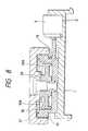
- Fig. 8is a sectional view of a rotary encoder with a push switch according to a second embodiment of this invention.
- Fig. 9is a perspective exploded view of a rotary member and a disk member in the rotary encoder with the push switch in Fig. 8.
- a rotary encoder with a push switchwill be described as an example of a rotatively-operated electronic component with a push switch.
- a rotary encoder with a push switchincludes an attachment base plate 1 provided with contacts.
- a rotary encoder portion 2 and a push switch portion 3are provided on the attachment base plate 1.
- the rotary encoder portion 2is movable relative to the attachment base plate 1 in a given range along a direction parallel to the attachment base plate 1.
- the push switch portion 3has a body (a casing) fixed to the attachment base plate 1.
- the attachment base plate 1includes a molded resin member of approximately a flat plate shape which is provided with a recess 5, a recess 7, and contact plates 9.
- Guide rails 4 for motion of the rotary encoder portion 2fixedly extend on the attachment base plate 1 along opposite side edges of the recess 5.
- a stop wall 6fixedly extends on the attachment base plate 1 along a rear edge of the recess 7. The stop wall 6 serves to hold or fix the push switch portion 3.
- the contact plates 9have connection terminals 8 for transmitting an electric signal from the rotary encoder portion 2 to an exterior.
- the rotary encoder portion 2includes a box-shaped casing 10, resilient contact arms (flexible contact arms) 11 and 12, a rotary member 15, and a disk-shaped or cylinder-shaped operation knob 17.
- the box-shaped casing 10fits into the recess 5 in the attachment base plate 1, and is movably or slidably held between the guide rails 4.
- the box-shaped casing 10is movable relative to the attachment base plate 1 in a given range along opposite directions (opposite directions denoted by arrows H1 in Figs. 1 and 4) parallel to the attachment base plate 4.
- the box-shaped casing 10is made of molded resin.
- the resilient contact arms 11extend from a contact member 35 along an upwardly sloping direction.
- the resilient contact arms 12extend from the contact member 35 along a downwardly sloping direction.
- the resilient contact arms 11, the resilient contact arms 12, and the contact member 35are integral with each other, and are made of suitable metal.
- the contact member 35is attached to the bottom walls of the box-shaped casing 10 by a suitable way such as an insert molding process.
- the rotary member 15is rotatably supported by a cylindrical shaft 13 integral with a central portion of the box-shaped casing 10. It should be noted that the cylindrical shaft 13 may be a member separate from the box-shaped casing 10 and mounted thereon.
- the rotary member 15has a disk shape. A lower surface of the rotary member 15 is provided with a contact plate 14 which can contact with the resilient contact arms 11.
- the contact plate 14has contact segments which are regularly arranged at equal intervals along a circumferential direction of the rotary member 15 (see Fig. 6).
- the rotary member 15is made of molded resin.
- the disk-shaped operation knob 17is attached to an upper portion of the rotary member 15 by a screw 16.
- the cylindrical shaft 13, the rotary member 15, and the disk-shaped operation knob 17are coaxial with each other.
- the rotary member 15rotates as the disk-shaped operation knob 17 rotates.
- the disk-shaped operation knob 17is designed so that it can be operated by touching outer cylindrical surfaces (outer circumferential surfaces) thereof.
- the attachment base plate 1has a pin-shaped upward projection 18 which supports a torsion coil spring 19 (see Fig. 6).
- the torsion coil spring 19urges a side surface of the box-shaped casing 10 relative to the pin-shaped upward projection 18 (that is, relative to the attachment base plate 1) in a direction parallel to the attachment base plate 1.
- the torsion coil spring 19holds the box-shaped casing 10 in a position remote from the push switch portion 3 while the resilient contact arms 12, which project downward from a lower surface of the box-shaped casing 10, are in contact with the contact plates 9 on the attachment base plate 1.
- the push switch portion 3fits into the recess 7 in the attachment base plate 1. A rear end of the push switch portion 3 contacts with the stop wall 6. Thereby, the body (the casing) of the push switch portion 3 is fixed to the attachment base plate 1.
- the push switch portion 3has an operation button 20 which faces the rotary encoder portion 2.
- a drive projection 21 integral with the box-shaped casing 10 of the rotary encoder portion 2contacts with a front end of the operation button 20 of the push switch portion 3.
- Fig. 5shows an example of conditions where the rotary encoder with the push switch is mounted on an electronic device.
- downwardly-projecting legs 1A and 1B on the attachment base plate 1are passed through attachment holes 24A and 24B in a printed wiring board 23 respectively.
- the connection terminals 8 of the rotary encoder portion 2are passed through attachment holes 25 in the printed wiring board 23, being soldered to wiring areas on the printed wiring board 23 respectively.
- Connection terminals 22 of the push switch portion 3are passed through attachment holes 26 in the printed wiring board 23, being soldered to wiring areas on the printed wiring board 23 respectively.
- An edge part or an outer part 17A of the disk-shaped operation knob 17 of the rotary encoder portion 2, which is remote from the push switch portion 3,emerges from a housing 27 of the electronic device via an opening therein. Thus, access to the disk-shaped knob is enabled.
- the edge part 17A of the disk-shaped operation knob 17projects outwardly from the housing 27 of the electronic device.
- the disk-shaped operation knob 17 of the rotary encoder portion 2can be rotated about the cylindrical shaft 13 at the center of the box-shaped casing 10 by applying a force to the projecting part 17A thereof along a tangential direction.
- at least one of the upwardly-projecting resilient contact arms 11sequentially moves into and out of touch with the contact segments of the contact plate 14 on the lower surface of the box-shaped casing 10 so that an electric pulse signal can be generated.
- the generated pulse signaldepends on the rotation of the disk-shaped operation knob 17.
- the pulse signaltravels from the upwardly-projecting resilient contact arms 11 to the downwardly-projecting resilient contact arms 12 via the contact member 35 before reaching the contact plates 9 on the attachment base plate 1 which are in contact with the resilient contact arms 12.
- the pulse signaltravels from the contact plates 9 to an electronic circuit on the printed wiring board 23 of the electronic device via the connection terminals 8.
- An electric signalcan be generated in response to the actuation of the operation button 20 of the push switch portion 3.
- the electric signalis transmitted from the push switch portion 3 to the circuit on the printed wiring board 23 of the electronic device via the connection terminals 22.
- the rotary encoder portion 2is returned to its normal position (see Fig. 6) by the force of the torsion coil spring 19 on the attachment base plate 1.
- means for transmitting an electric signal from the rotary encoder portion 2 to the connection terminals 8 on the attachment base plate 1includes the resilient contact arms 12 which project downwardly from the lower surface of the box-shaped casing 10 and which are in contact with the contact plates 9 on the attachment base plate 1.
- This arrangementmay be replaced by the following design. Contact plates are provided on a lower surface of the box-shaped casing 10 while resilient contact arms in contact with the contact plates are provided on the attachment base plate 1.
- the rotary encoder portion 2may be replaced by another rotatively-operated electronic component such as a rotary variable resistor.
- the rotary encoder with the push switchhas advantages as follows.
- the rotary encoder portion 2is operated by actuating the disk-shaped operation knob 17.
- the push switch portion 3is operated by actuating the disk-shaped operation knob 17. Accordingly, the operation button 20 of the push switch portion 3 can be small. This enables a small see of the rotary encoder with the push switch.
- the rotary encoder portion 2 and the push switch portion 3are operated by actuating only the disk-shaped operation knob 17.
- the rotary encoder portion 2 and the push switch portion 3are provided in common on the attachment base plate 1. Therefore, the rotary encoder with the push switch can be handled as a single unit or a single electronic component. Furthermore, the positional relation between the rotary encoder portion 2 and the push switch portion 3 can be accurately maintained. In addition, the rotary encoder with the push switch can be easily attached to an electronic device.
- Fig. 8shows a second embodiment of this invention which is similar to the embodiment of Figs. 1-7 except for design changes indicated hereinafter.
- the embodiment of Fig. 8includes a rotary member 28 corresponding to the rotary member 15 of Fig. 3. As shown in Fig. 9, the rotary member 28 has an uneven upper surface 28A formed with projections and recesses extending radially.
- the embodiment of Fig. 8includes a disk member 30 fixed to a box-shaped casing 10. As shown in Fig. 9, the disk member 30 has a circumferentially-extending resilient portion formed with a downward projection 30A. The downward projection 30A on the disk member 30 engages the upper surface 28A of the rotary member 28.
- the embodiment of Fig. 8includes a disk-shaped operation knob 31 corresponding to the disk-shaped operation knob 17 of Fig. 3.
- the downward projection 30A on the disk member 30relatively rotates and slides on the upper surface 28A of the rotary member 28 while following the unevenness in the upper surface 28A of the rotary member 28.
- the contact between the downward projection 30A on the disk member 30 and the uneven upper surface 28A of the rotary member 28provides a suitable resistance to the rotation of the rotary member 28, that is, the rotation of the disk-shaped operation knob 31.
- the contact between the downward projection 30A on the disk member 30 and the uneven upper surface 28A of the rotary member 28prevents the disk-shaped operation knob 31 from being erroneously rotated.
Landscapes
- Switches With Compound Operations (AREA)
Description
- This invention relates to a rotatively-operated electroniccomponent with a push switch according to the preamble of
claim 1, as for example known from EP-A-531 829 which is usable in various electronicdevices such as a remote-controller operation unit or a portableelectronic device. - It is known that a rotatively-operated electronic componentand a push switch which have different knobs are separatelyprovided in an electronic device. A typical example of therotatively-operated electronic component is a rotary encoder havinga knob which is rotatable about an axis perpendicular to a mainplane of an encoder body. In the above-indicated knownarrangement, the total space occupied by the two knobs tends to berelatively large. This causes a barrier to the miniaturization of thearrangement. To operate the electronic component and the pushswitch, it is necessary to actuate both the two knobs. This causesinconvenience.
- It is an object of this invention to provide a small electroniccomponent with a push switch.
- It is another object of this invention to provide an easily-operatedelectronic component with a push switch.
- A first aspect of this invention provides a rotatively-operatedelectronic component with a push switch which comprises anattachment base plate; a rotatively-operated electronic componentportion supported on the attachment base plate and including arotatable operation knob, and means for generating an electricsignal in response to rotation of the operation knob; means forallowing the rotatively-operated electronic component portion tomove relative to the attachment base plate by application of a forceto the operation knob; a push switch portion supported on theattachment base plate; and means for actuating the push switchportion in response to movement of the rotatively-operatedelectronic component portion relative to the attachment base plateby the application of the force to the operation knob.
- A second aspect of this invention is based on the first aspectthereof, and provides a rotatively-operated electronic componentwith a push switch which further comprises means for providing aresistance to rotation of the operation knob, the resistance-providingmeans including a rotary member rotatable together withthe operation knob and having an uneven surface, a resilientmember fixed to a casing of the rotatively-operated electroniccomponent portion and having a projection in contact with theuneven surface of the rotary member.
- A third aspect of this invention is based on the first aspectthereof, and provides a rotatively-operated electronic componentwith a push switch which further comprises a first resilient contactarm provided in the electric-signal generating means, and a second resilient contact arm for transmitting the electric signal from therotatively-operated electronic component portion to a contact onthe attachment base plate, the first resilient contact arm and thesecond resilient contact arm being formed by a common resilientmetal plate.
- Fig. 1 is a perspective view of a rotary encoder with a pushswitch according to a first embodiment of this invention.
- Fig. 2 is a perspective view of an attachment base plate in therotary encoder with the push switch in Fig. 1.
- Fig. 3 is a first sectional view of the rotary encoder with thepush switch in Fig. 1.
- Fig. 4 is a second sectional view of the rotary encoder with thepush switch in Fig. 1.
- Fig. 5 is a sectional view of an electronic device and the rotaryencoder with the push switch in Fig. 1.
- Fig. 6 is a top view, with a portion broken away, of the rotaryencoder with the push switch in Fig. 1.
- Fig. 7 is another top view of the rotary encoder with the pushswitch in Fig. 1.
- Fig. 8 is a sectional view of a rotary encoder with a pushswitch according to a second embodiment of this invention.
- Fig. 9 is a perspective exploded view of a rotary member and adisk member in the rotary encoder with the push switch in Fig. 8.
- Regarding a first embodiment of this invention, a rotaryencoder with a push switch will be described as an example of arotatively-operated electronic component with a push switch.
- With reference to Fig. 1, a rotary encoder with a push switchincludes an
attachment base plate 1 provided with contacts. Arotary encoder portion 2 and apush switch portion 3 are providedon theattachment base plate 1. Therotary encoder portion 2 ismovable relative to theattachment base plate 1 in a given rangealong a direction parallel to theattachment base plate 1. Thepushswitch portion 3 has a body (a casing) fixed to theattachment baseplate 1. - With reference to Fig. 2, the
attachment base plate 1 includesa molded resin member of approximately a flat plate shape which isprovided with arecess 5, arecess 7, andcontact plates 9.Guiderails 4 for motion of therotary encoder portion 2 fixedly extend ontheattachment base plate 1 along opposite side edges of therecess 5. Astop wall 6 fixedly extends on theattachment base plate 1along a rear edge of therecess 7. Thestop wall 6 serves to hold orfix thepush switch portion 3. Thecontact plates 9 haveconnectionterminals 8 for transmitting an electric signal from therotaryencoder portion 2 to an exterior. - As shown in Figs. 3 and 4, the
rotary encoder portion 2includes a box-shaped casing 10, resilient contact arms (flexiblecontact arms) 11 and 12, arotary member 15, and a disk-shaped orcylinder-shaped operation knob 17. The box-shaped casing 10 fits into therecess 5 in theattachment base plate 1, and is movably orslidably held between theguide rails 4. The box-shaped casing 10 ismovable relative to theattachment base plate 1 in a given rangealong opposite directions (opposite directions denoted by arrowsH1 in Figs. 1 and 4) parallel to theattachment base plate 4. Thebox-shaped casing 10 is made of molded resin. Theresilientcontact arms 11 extend from acontact member 35 along anupwardly sloping direction. On the other hand, theresilient contactarms 12 extend from thecontact member 35 along a downwardlysloping direction. Theresilient contact arms 11, theresilientcontact arms 12, and thecontact member 35 are integral with eachother, and are made of suitable metal. Thecontact member 35 isattached to the bottom walls of the box-shaped casing 10 by asuitable way such as an insert molding process. Therotary member 15 is rotatably supported by acylindrical shaft 13 integral with acentral portion of the box-shaped casing 10. It should be noted thatthecylindrical shaft 13 may be a member separate from the box-shapedcasing 10 and mounted thereon. Therotary member 15 hasa disk shape. A lower surface of therotary member 15 is providedwith acontact plate 14 which can contact with theresilient contactarms 11. Thecontact plate 14 has contact segments which areregularly arranged at equal intervals along a circumferentialdirection of the rotary member 15 (see Fig. 6). Therotary member 15 is made of molded resin. The disk-shaped operation knob 17 isattached to an upper portion of therotary member 15 by ascrew 16. Thecylindrical shaft 13, therotary member 15, and the disk-shaped operation knob 17 are coaxial with each other. Therotarymember 15 rotates as the disk-shaped operation knob 17 rotates.The disk-shaped operation knob 17 is designed so that it can beoperated by touching outer cylindrical surfaces (outercircumferential surfaces) thereof. - The
attachment base plate 1 has a pin-shapedupwardprojection 18 which supports a torsion coil spring 19 (see Fig. 6).Thetorsion coil spring 19 urges a side surface of the box-shapedcasing 10 relative to the pin-shaped upward projection 18 (that is,relative to the attachment base plate 1) in a direction parallel to theattachment base plate 1. Normally, thetorsion coil spring 19 holdsthe box-shaped casing 10 in a position remote from thepush switchportion 3 while theresilient contact arms 12, which projectdownward from a lower surface of the box-shaped casing 10, are incontact with thecontact plates 9 on theattachment base plate 1. - As shown in Fig. 4, the
push switch portion 3 fits into therecess 7 in theattachment base plate 1. A rear end of thepushswitch portion 3 contacts with thestop wall 6. Thereby, the body(the casing) of thepush switch portion 3 is fixed to theattachmentbase plate 1. Thepush switch portion 3 has anoperation button 20which faces therotary encoder portion 2. Adrive projection 21integral with the box-shaped casing 10 of therotary encoderportion 2 contacts with a front end of theoperation button 20 of thepush switch portion 3. - Fig. 5 shows an example of conditions where the rotaryencoder with the push switch is mounted on an electronic device. With reference to Fig. 5, downwardly-projecting
legs attachment base plate 1 are passed throughattachment holes wiring board 23 respectively. Theconnection terminals 8 of therotary encoder portion 2 are passedthroughattachment holes 25 in the printedwiring board 23, beingsoldered to wiring areas on the printedwiring board 23respectively.Connection terminals 22 of thepush switch portion 3are passed through attachment holes 26 in the printedwiring board 23, being soldered to wiring areas on the printedwiring board 23respectively. An edge part or anouter part 17A of the disk-shapedoperation knob 17 of therotary encoder portion 2, which is remotefrom thepush switch portion 3, emerges from ahousing 27 of theelectronic device via an opening therein. Thus, access to the disk-shapedknob is enabled. - Hereinafter, a description will be given of operation of therotary encoder with the push switch. With reference to Figs. 5 and6, the
edge part 17A of the disk-shapedoperation knob 17 projectsoutwardly from thehousing 27 of the electronic device. The disk-shapedoperation knob 17 of therotary encoder portion 2 can berotated about thecylindrical shaft 13 at the center of the box-shapedcasing 10 by applying a force to the projectingpart 17Athereof along a tangential direction. During rotation of the disk-shapedoperation knob 17, at least one of the upwardly-projectingresilient contact arms 11 sequentially moves into and out of touchwith the contact segments of thecontact plate 14 on the lowersurface of the box-shapedcasing 10 so that an electric pulse signal can be generated. The generated pulse signal depends on therotation of the disk-shapedoperation knob 17. - The pulse signal travels from the upwardly-projecting
resilientcontact arms 11 to the downwardly-projectingresilient contactarms 12 via thecontact member 35 before reaching thecontactplates 9 on theattachment base plate 1 which are in contact withtheresilient contact arms 12. The pulse signal travels from thecontact plates 9 to an electronic circuit on the printedwiring board 23 of the electronic device via theconnection terminals 8. - With reference to Figs. 5 and 7, in the case where theprojecting
part 17A of the disk-shapedoperation knob 17 of therotary encoder portion 2 is depressed relative to thehousing 27 ofthe electronic device along a direction H2 parallel to theattachment base plate 1 (that is, a direction of the line connectingthe center of theknob 17 and the center of the push switch portion3), the whole of therotary encoder portion 2 can be moved alongtheguide rails 4 on theattachment base plate 1 against the force ofthetorsion coil spring 19 on theattachment base plate 1. Thedriveprojection 21 on the box-shapedcasing 10 moves together with therotary encoder portion 2, depressing and actuating theoperationbutton 20 of thepush switch portion 3. An electric signal can begenerated in response to the actuation of theoperation button 20 ofthepush switch portion 3. The electric signal is transmitted fromthepush switch portion 3 to the circuit on the printedwiring board 23 of the electronic device via theconnection terminals 22. Whenthe depressing force is removed from the disk-shapedoperation knob 17, therotary encoder portion 2 is returned to its normalposition (see Fig. 6) by the force of thetorsion coil spring 19 on theattachment base plate 1. - As understood from the previous description, means fortransmitting an electric signal from the
rotary encoder portion 2 totheconnection terminals 8 on theattachment base plate 1 includestheresilient contact arms 12 which project downwardly from thelower surface of the box-shapedcasing 10 and which are in contactwith thecontact plates 9 on theattachment base plate 1. Thisarrangement may be replaced by the following design. Contactplates are provided on a lower surface of the box-shapedcasing 10while resilient contact arms in contact with the contact plates areprovided on theattachment base plate 1. - The
rotary encoder portion 2 may be replaced by anotherrotatively-operated electronic component such as a rotary variableresistor. - The rotary encoder with the push switch has advantages asfollows. The
rotary encoder portion 2 is operated by actuating thedisk-shapedoperation knob 17. Also, thepush switch portion 3 isoperated by actuating the disk-shapedoperation knob 17.Accordingly, theoperation button 20 of thepush switch portion 3can be small. This enables a small see of the rotary encoder withthe push switch. As previously described, therotary encoderportion 2 and thepush switch portion 3 are operated by actuatingonly the disk-shapedoperation knob 17. Thus, the rotary encoderwith the push switch can be easily and quickly operated. Therotary encoder portion 2 and thepush switch portion 3 are provided incommon on theattachment base plate 1. Therefore, the rotaryencoder with the push switch can be handled as a single unit or asingle electronic component. Furthermore, the positional relationbetween therotary encoder portion 2 and thepush switch portion 3can be accurately maintained. In addition, the rotary encoder withthe push switch can be easily attached to an electronic device. - Fig. 8 shows a second embodiment of this invention which issimilar to the embodiment of Figs. 1-7 except for design changesindicated hereinafter.
- The embodiment of Fig. 8 includes a
rotary member 28corresponding to therotary member 15 of Fig. 3. As shown in Fig.9, therotary member 28 has an unevenupper surface 28A formedwith projections and recesses extending radially. The embodimentof Fig. 8 includes adisk member 30 fixed to a box-shapedcasing 10.As shown in Fig. 9, thedisk member 30 has a circumferentially-extendingresilient portion formed with adownward projection 30A. Thedownward projection 30A on thedisk member 30engages theupper surface 28A of therotary member 28. - The embodiment of Fig. 8 includes a disk-shaped
operationknob 31 corresponding to the disk-shapedoperation knob 17 of Fig.3. During rotation of the disk-shapedoperation knob 31, thedownward projection 30A on thedisk member 30 relatively rotatesand slides on theupper surface 28A of therotary member 28 whilefollowing the unevenness in theupper surface 28A of therotary member 28. In this case, the contact between thedownwardprojection 30A on thedisk member 30 and the unevenuppersurface 28A of therotary member 28 provides a suitable resistanceto the rotation of therotary member 28, that is, the rotation of thedisk-shapedoperation knob 31. Furthermore, during an action ofpressing the disk-shapedoperation knob 31 to actuate apushswitch portion 3, the contact between thedownward projection 30A on thedisk member 30 and the unevenupper surface 28A oftherotary member 28 prevents the disk-shapedoperation knob 31from being erroneously rotated.
Claims (5)
- A rotatively-operated electronic component with a pushswitch, comprising:an attachment base plate (1);a rotatively-operated electronic component portion (2)supported on said attachment base-plate (1) and including arotatable operation knob (17; 31);a means (11, 12, 14, 15) for generating an electricsignal in response to a rotation of said operation knob(17; 31);a means (4) for allowing said rotatively-operatedelectronic component portion (2) to move relative to saidattachment base plate (1) by application of a force to saidoperation knob (17; 31);a push switch portion (3) supported on said attachmentbase plate (1); anda means (21) for actuating said push switch portion(3) in response to a movement of said rotatively-operatedelectronic component portion (2) relative to saidattachment base plate (1) by said application of said forceto said operation knob (17; 31),characterized in thatsaid means (11, 12, 14, 15) for generating an electric signal is included in saidrotatively-operated electronic component portion (2), andis movable relative to said attachment base plate togetherwith said operation knob (17; 31).
- A rotatively-operated electronic component with a pushswitch as recited in claim 1, further comprising a meansfor providing a resistance to rotation of said operationknob (31), said resistance-providing means including arotary member (28) rotatable together with said operationknob (31) and having an uneven surface (28A), a resilientmember (30) fixed to a casing (10) of said rotatively-operatedelectronic component portion (2) and having aprojection (30A) in contact with said uneven surface (28A)of said rotary member (28).
- A rotatively-operated electronic component with a pushswitch as recited in claim 1, further comprising a firstresilient contact arm (11) provided in said electric-signalgenerating means (11, 12, 14, 15), and a second resilientcontact arm (12) for transmitting said electric signal fromsaid rotatively-operated electronic component portion (2)to a contact (9) on said attachment base plate (1), saidfirst resilient contact arm (11) and said second resilientcontact arm (12) being formed by a common resilient metalplate.
- A rotatively-operated electronic component with a pushswitch as recited in one of claims 1 to 3, wherein saidelectronic component includesa body (10), wherein said operation knob (12) isrotatable relative to said body (10) ;a means (4, 5) for supporting said electroniccomponent on said attachment base plate (1); anda means (6) for supporting said push switch portion (3) onsaid attachment base plate; whereinsaid push switch portion (3) includes an operationbutton (20) which is actuated by said means (21).
- A rotatively-operated electronic component with a pushswitch as recited in claim 4, wherein said means (21) foractuating said operation button (20) is a part of said body(10) of said electronic component.
Applications Claiming Priority (3)
| Application Number | Priority Date | Filing Date | Title |
|---|---|---|---|
| JP00856795AJP3222714B2 (en) | 1995-01-24 | 1995-01-24 | Pressing and rotating electronic parts |
| JP856795 | 1995-01-24 | ||
| JP8567/95 | 1995-01-24 |
Publications (3)
| Publication Number | Publication Date |
|---|---|
| EP0724278A2 EP0724278A2 (en) | 1996-07-31 |
| EP0724278A3 EP0724278A3 (en) | 1997-10-29 |
| EP0724278B1true EP0724278B1 (en) | 2001-04-04 |
Family
ID=11696645
Family Applications (1)
| Application Number | Title | Priority Date | Filing Date |
|---|---|---|---|
| EP96100916AExpired - LifetimeEP0724278B1 (en) | 1995-01-24 | 1996-01-23 | Rotatively-operated electronic component with push switch |
Country Status (6)
| Country | Link |
|---|---|
| US (1) | US5613600A (en) |
| EP (1) | EP0724278B1 (en) |
| JP (1) | JP3222714B2 (en) |
| KR (1) | KR100237554B1 (en) |
| CN (1) | CN1074161C (en) |
| DE (1) | DE69612313T2 (en) |
Families Citing this family (62)
| Publication number | Priority date | Publication date | Assignee | Title |
|---|---|---|---|---|
| EP0847069B1 (en)* | 1995-08-23 | 2004-02-11 | Matsushita Electric Industrial Co., Ltd. | Operation type electronic component |
| KR100191720B1 (en)* | 1996-01-15 | 1999-06-15 | 구자홍 | Analog keyboard apparatus using encoder switch |
| TW369658B (en)* | 1997-03-13 | 1999-09-11 | Alps Electric Co Ltd | Rotary operation electric components and the coordinate input apparatus using the rotary operation electric components |
| JPH117865A (en)* | 1997-04-21 | 1999-01-12 | Matsushita Electric Ind Co Ltd | Rotary operation type electronic component with push switch |
| JP3437054B2 (en)* | 1997-05-12 | 2003-08-18 | アルプス電気株式会社 | Multi-input switch |
| US6097964A (en) | 1997-09-04 | 2000-08-01 | Nokia Mobile Phones Limited | Navigation key for a handset |
| DE19747284B4 (en)* | 1997-10-25 | 2010-06-02 | Robert Bosch Gmbh | Control element for electronic devices |
| GB9722766D0 (en) | 1997-10-28 | 1997-12-24 | British Telecomm | Portable computers |
| JP4019515B2 (en)* | 1998-08-21 | 2007-12-12 | 松下電器産業株式会社 | Push / turn operation type electronic component and communication terminal device using the same |
| JP3951485B2 (en)* | 1998-12-25 | 2007-08-01 | 松下電器産業株式会社 | Rotating / pressing operation type electronic parts and electronic equipment using the same |
| JP4055281B2 (en)* | 1999-02-10 | 2008-03-05 | 松下電器産業株式会社 | Press / rotate electronic components |
| JP3991491B2 (en)* | 1999-03-01 | 2007-10-17 | 松下電器産業株式会社 | Rotating / pressing operation type electronic parts and electronic equipment using the same |
| TW419581B (en)* | 1999-03-08 | 2001-01-21 | Acer Comm & Multimedia Inc | Rotary encoder |
| EP1052565A3 (en)* | 1999-05-13 | 2005-05-11 | Sony Corporation | Information processing method and apparatus |
| TW421923B (en)* | 1999-05-27 | 2001-02-11 | Acer Peripherals Inc | Electronic device for integrating rotary encoder and push switch |
| TW508606B (en)* | 1999-07-27 | 2002-11-01 | Alps Electric Co Ltd | Multi-directional input device |
| US6401030B1 (en) | 1999-11-12 | 2002-06-04 | Sony Corporation | Information processing apparatus and method, and program storage medium |
| JP3956554B2 (en)* | 1999-11-19 | 2007-08-08 | 松下電器産業株式会社 | Rotary encoder and composite operation type electronic component using the same |
| JP3869996B2 (en)* | 2000-03-10 | 2007-01-17 | アルプス電気株式会社 | Multi-directional input device |
| US7345671B2 (en) | 2001-10-22 | 2008-03-18 | Apple Inc. | Method and apparatus for use of rotational user inputs |
| US7312785B2 (en) | 2001-10-22 | 2007-12-25 | Apple Inc. | Method and apparatus for accelerated scrolling |
| US7046230B2 (en) | 2001-10-22 | 2006-05-16 | Apple Computer, Inc. | Touch pad handheld device |
| US7333092B2 (en) | 2002-02-25 | 2008-02-19 | Apple Computer, Inc. | Touch pad for handheld device |
| US6809275B1 (en) | 2002-05-13 | 2004-10-26 | Synaptics, Inc. | Rotary and push type input device |
| JP4084138B2 (en)* | 2002-09-05 | 2008-04-30 | アルプス電気株式会社 | Rotating operation type electric parts |
| FI20021759A0 (en)* | 2002-10-03 | 2002-10-03 | Nokia Corp | Method and interface for entering text |
| EP1455370B1 (en)* | 2003-03-04 | 2006-06-07 | Sonion Roskilde A/S | Combined roller and push switch assembly |
| US7499040B2 (en) | 2003-08-18 | 2009-03-03 | Apple Inc. | Movable touch pad with added functionality |
| US8059099B2 (en) | 2006-06-02 | 2011-11-15 | Apple Inc. | Techniques for interactive input to portable electronic devices |
| US7495659B2 (en) | 2003-11-25 | 2009-02-24 | Apple Inc. | Touch pad for handheld device |
| US7976793B2 (en)* | 2003-11-27 | 2011-07-12 | Gilson S.A.S. | Electronic pipette |
| KR100804790B1 (en) | 2004-03-10 | 2008-02-20 | 삼성전자주식회사 | Scroll key with function selector switch |
| TWI236689B (en)* | 2004-08-16 | 2005-07-21 | Inventec Multimedia & Telecom | Portable electronic device with quick click-selection |
| KR100597744B1 (en)* | 2004-08-16 | 2006-07-07 | 삼성전자주식회사 | Portable computer with scroll wheel on the side |
| DE102004054927A1 (en) | 2004-11-13 | 2006-06-01 | Hansaton Akustik Gmbh | Hearing aid with volume control wheel |
| US7781692B2 (en) | 2005-07-30 | 2010-08-24 | Siemens Audiologische Technik Gmbh | Switch |
| EP1750194B1 (en)* | 2005-08-05 | 2010-05-05 | Niles Co., Ltd. | Multi directional input apparatus |
| US20070152983A1 (en) | 2005-12-30 | 2007-07-05 | Apple Computer, Inc. | Touch pad with symbols based on mode |
| JP4638829B2 (en)* | 2006-03-14 | 2011-02-23 | アルプス電気株式会社 | Compound operation input device |
| EP1852882A3 (en) | 2006-05-01 | 2009-07-29 | Sonion Roskilde A/S | A multi-functional control |
| US8743060B2 (en) | 2006-07-06 | 2014-06-03 | Apple Inc. | Mutual capacitance touch sensing device |
| US9360967B2 (en) | 2006-07-06 | 2016-06-07 | Apple Inc. | Mutual capacitance touch sensing device |
| US8022935B2 (en) | 2006-07-06 | 2011-09-20 | Apple Inc. | Capacitance sensing electrode with integrated I/O mechanism |
| US8274479B2 (en) | 2006-10-11 | 2012-09-25 | Apple Inc. | Gimballed scroll wheel |
| JP4769757B2 (en)* | 2007-04-11 | 2011-09-07 | アルプス電気株式会社 | Manual input device |
| WO2009002039A2 (en)* | 2007-06-22 | 2008-12-31 | Youn Soo Kim | Button for electric product |
| US9654104B2 (en)* | 2007-07-17 | 2017-05-16 | Apple Inc. | Resistive force sensor with capacitive discrimination |
| US20090059459A1 (en)* | 2007-08-31 | 2009-03-05 | Speed Tech Corp. | Electrostatic receiving mechanism of electronic indicating device |
| US8683378B2 (en) | 2007-09-04 | 2014-03-25 | Apple Inc. | Scrolling techniques for user interfaces |
| US8416198B2 (en) | 2007-12-03 | 2013-04-09 | Apple Inc. | Multi-dimensional scroll wheel |
| CN101471198B (en)* | 2007-12-26 | 2010-10-27 | 英业达股份有限公司 | Roller assembly and electronic device using same |
| USD587661S1 (en)* | 2008-03-12 | 2009-03-03 | Cts Corporation | Actuator |
| US9454256B2 (en) | 2008-03-14 | 2016-09-27 | Apple Inc. | Sensor configurations of an input device that are switchable based on mode |
| US9354751B2 (en) | 2009-05-15 | 2016-05-31 | Apple Inc. | Input device with optimized capacitive sensing |
| US8872771B2 (en) | 2009-07-07 | 2014-10-28 | Apple Inc. | Touch sensing device having conductive nodes |
| TWI440954B (en)* | 2011-03-14 | 2014-06-11 | Ability Entpr Co Ltd | Control mechanism |
| TW201241598A (en)* | 2011-04-07 | 2012-10-16 | Hon Hai Prec Ind Co Ltd | Power adapter |
| JP5626591B2 (en)* | 2011-04-14 | 2014-11-19 | アルプス電気株式会社 | Input device |
| FI125309B (en)* | 2012-03-30 | 2015-08-31 | Sartorius Biohit Liquid Handling Oy | Steering wheel for pipette |
| US9268356B2 (en) | 2013-03-15 | 2016-02-23 | Touchsensor Technologies, Llc | Modular knob system |
| CN109617548B (en)* | 2018-12-07 | 2022-08-30 | 业成科技(成都)有限公司 | Touch control knob device capable of being attached to curved surface |
| USD1032546S1 (en)* | 2019-02-20 | 2024-06-25 | Sonceboz Mechatronics Boncourt | Electric actuator |
Family Cites Families (12)
| Publication number | Priority date | Publication date | Assignee | Title |
|---|---|---|---|---|
| US3231696A (en)* | 1963-12-20 | 1966-01-25 | Burroughs Corp | Centrifugal switch having a pair of spaced apart printed circuit contact plates |
| DE6812711U (en)* | 1968-12-21 | 1969-09-18 | Sel Kontakt Bauelemente G M B | ROTARY SWITCH WITH LATCH DEVICE |
| JPS5957821U (en)* | 1982-10-08 | 1984-04-16 | アルプス電気株式会社 | rotary pulse switch |
| DE8713156U1 (en)* | 1987-09-30 | 1987-12-10 | La Télémécanique Electrique, Nanterre, Hauts-de-Seine | Rotary switch for at least two control elements to be operated |
| US5008496A (en)* | 1988-09-15 | 1991-04-16 | Siemens Aktiengesellschaft | Three-dimensional printed circuit board |
| US5145059A (en)* | 1989-06-29 | 1992-09-08 | Prince Corporation | Switch |
| US4996401A (en)* | 1989-06-29 | 1991-02-26 | Prince Corporation | Switch |
| JPH03147116A (en)* | 1989-11-02 | 1991-06-24 | Mitsubishi Electric Corp | Owned portable semiconductor storage device |
| US5043546A (en)* | 1990-07-16 | 1991-08-27 | Oslo Controls, Incorporated | Push-button switch |
| US5063276A (en)* | 1990-08-20 | 1991-11-05 | Eaton Corporation | Pushbutton switch with rotational contact wiping action |
| US5448240A (en)* | 1991-08-29 | 1995-09-05 | Alps Electric Co., Ltd. | Remote control input device |
| US5180050A (en)* | 1991-10-15 | 1993-01-19 | Delco Electronics Corporation | Pushbutton rotary switch |
- 1995
- 1995-01-24JPJP00856795Apatent/JP3222714B2/ennot_activeExpired - Fee Related
- 1996
- 1996-01-03USUS08/582,501patent/US5613600A/ennot_activeExpired - Lifetime
- 1996-01-23DEDE69612313Tpatent/DE69612313T2/ennot_activeExpired - Lifetime
- 1996-01-23EPEP96100916Apatent/EP0724278B1/ennot_activeExpired - Lifetime
- 1996-01-24CNCN96101913Apatent/CN1074161C/ennot_activeExpired - Fee Related
- 1996-01-24KRKR1019960001509Apatent/KR100237554B1/ennot_activeExpired - Fee Related
Also Published As
| Publication number | Publication date |
|---|---|
| US5613600A (en) | 1997-03-25 |
| EP0724278A3 (en) | 1997-10-29 |
| DE69612313T2 (en) | 2001-08-30 |
| JPH08203387A (en) | 1996-08-09 |
| KR960030279A (en) | 1996-08-17 |
| DE69612313D1 (en) | 2001-05-10 |
| CN1135612A (en) | 1996-11-13 |
| EP0724278A2 (en) | 1996-07-31 |
| KR100237554B1 (en) | 2000-01-15 |
| JP3222714B2 (en) | 2001-10-29 |
| CN1074161C (en) | 2001-10-31 |
Similar Documents
| Publication | Publication Date | Title |
|---|---|---|
| EP0724278B1 (en) | Rotatively-operated electronic component with push switch | |
| EP0750327B1 (en) | Rotatively-operated electronic component with push switch | |
| US6388212B1 (en) | Push and rotary operating type electronic component | |
| US6525277B2 (en) | Multiple operation type input device | |
| US5711415A (en) | Rotary electronic component with push switch | |
| JP2000003637A (en) | Inclinable stick type indicating device | |
| KR100420190B1 (en) | Multi-operation switch device | |
| EP1477999B1 (en) | Switching device including stopper surface-mounted on printed circuit board | |
| JP2007227337A (en) | Multidirectional input device | |
| JP3763711B2 (en) | Composite operation type electronic parts | |
| EP1708220B1 (en) | Multi-operational input device | |
| JP2001345031A (en) | Composite operating type electronic parts | |
| US6396016B1 (en) | Electronic component incorporating push switch and rotary encoder | |
| JP2006224860A (en) | Steering switch device | |
| JP2001196207A (en) | Rotary type electrical part having click | |
| JP2539073Y2 (en) | Rotary electronic components with pushbutton switches | |
| JP3931528B2 (en) | Press / rotation operation type electronic components and electronic equipment using the same | |
| JP2001325860A (en) | Composite switching device | |
| JP3931532B2 (en) | Multi-directional electronic component and electronic equipment using the same | |
| JP4013442B2 (en) | Pressing / rotating operation type electronic component and its mounting method | |
| JP3112437B2 (en) | Pressing / rotating operation type electronic components | |
| JP2006228620A (en) | Steering switching device | |
| JP3579960B2 (en) | Rotary operation type electronic component with push switch | |
| JP3531271B2 (en) | Rotary operation type electronic component with push switch | |
| JP3222811B2 (en) | Pressing / rotating operation type electronic components |
Legal Events
| Date | Code | Title | Description |
|---|---|---|---|
| PUAI | Public reference made under article 153(3) epc to a published international application that has entered the european phase | Free format text:ORIGINAL CODE: 0009012 | |
| 17P | Request for examination filed | Effective date:19960123 | |
| AK | Designated contracting states | Kind code of ref document:A2 Designated state(s):DE FR GB | |
| PUAL | Search report despatched | Free format text:ORIGINAL CODE: 0009013 | |
| AK | Designated contracting states | Kind code of ref document:A3 Designated state(s):DE FR GB | |
| 17Q | First examination report despatched | Effective date:19991005 | |
| GRAG | Despatch of communication of intention to grant | Free format text:ORIGINAL CODE: EPIDOS AGRA | |
| GRAG | Despatch of communication of intention to grant | Free format text:ORIGINAL CODE: EPIDOS AGRA | |
| GRAH | Despatch of communication of intention to grant a patent | Free format text:ORIGINAL CODE: EPIDOS IGRA | |
| GRAH | Despatch of communication of intention to grant a patent | Free format text:ORIGINAL CODE: EPIDOS IGRA | |
| GRAA | (expected) grant | Free format text:ORIGINAL CODE: 0009210 | |
| AK | Designated contracting states | Kind code of ref document:B1 Designated state(s):DE FR GB | |
| REF | Corresponds to: | Ref document number:69612313 Country of ref document:DE Date of ref document:20010510 | |
| ET | Fr: translation filed | ||
| REG | Reference to a national code | Ref country code:GB Ref legal event code:IF02 | |
| PLBE | No opposition filed within time limit | Free format text:ORIGINAL CODE: 0009261 | |
| STAA | Information on the status of an ep patent application or granted ep patent | Free format text:STATUS: NO OPPOSITION FILED WITHIN TIME LIMIT | |
| 26N | No opposition filed | ||
| PGFP | Annual fee paid to national office [announced via postgrant information from national office to epo] | Ref country code:DE Payment date:20140115 Year of fee payment:19 | |
| PGFP | Annual fee paid to national office [announced via postgrant information from national office to epo] | Ref country code:FR Payment date:20140108 Year of fee payment:19 | |
| PGFP | Annual fee paid to national office [announced via postgrant information from national office to epo] | Ref country code:GB Payment date:20140122 Year of fee payment:19 | |
| REG | Reference to a national code | Ref country code:DE Ref legal event code:R119 Ref document number:69612313 Country of ref document:DE | |
| GBPC | Gb: european patent ceased through non-payment of renewal fee | Effective date:20150123 | |
| PG25 | Lapsed in a contracting state [announced via postgrant information from national office to epo] | Ref country code:GB Free format text:LAPSE BECAUSE OF NON-PAYMENT OF DUE FEES Effective date:20150123 Ref country code:DE Free format text:LAPSE BECAUSE OF NON-PAYMENT OF DUE FEES Effective date:20150801 | |
| REG | Reference to a national code | Ref country code:FR Ref legal event code:ST Effective date:20150930 | |
| PG25 | Lapsed in a contracting state [announced via postgrant information from national office to epo] | Ref country code:FR Free format text:LAPSE BECAUSE OF NON-PAYMENT OF DUE FEES Effective date:20150202 |