EP0723763A1 - Aiming device for linearly introducing an instrument into a human body - Google Patents
Aiming device for linearly introducing an instrument into a human bodyDownload PDFInfo
- Publication number
- EP0723763A1 EP0723763A1EP96100001AEP96100001AEP0723763A1EP 0723763 A1EP0723763 A1EP 0723763A1EP 96100001 AEP96100001 AEP 96100001AEP 96100001 AEP96100001 AEP 96100001AEP 0723763 A1EP0723763 A1EP 0723763A1
- Authority
- EP
- European Patent Office
- Prior art keywords
- guide
- laser device
- computer tomograph
- laser
- housing
- Prior art date
- Legal status (The legal status is an assumption and is not a legal conclusion. Google has not performed a legal analysis and makes no representation as to the accuracy of the status listed.)
- Granted
Links
- 238000003780insertionMethods0.000claimsabstractdescription8
- 230000037431insertionEffects0.000claimsabstractdescription8
- 230000000295complement effectEffects0.000claimsdescription2
- 238000003325tomographyMethods0.000abstract1
- 238000001574biopsyMethods0.000description2
- 210000000988bone and boneAnatomy0.000description2
- 238000002347injectionMethods0.000description2
- 239000007924injectionSubstances0.000description2
- 210000000056organAnatomy0.000description2
- 238000000034methodMethods0.000description1
- 230000005855radiationEffects0.000description1
- 210000001519tissueAnatomy0.000description1
Images


Classifications
- A—HUMAN NECESSITIES
- A61—MEDICAL OR VETERINARY SCIENCE; HYGIENE
- A61B—DIAGNOSIS; SURGERY; IDENTIFICATION
- A61B6/00—Apparatus or devices for radiation diagnosis; Apparatus or devices for radiation diagnosis combined with radiation therapy equipment
- A61B6/08—Auxiliary means for directing the radiation beam to a particular spot, e.g. using light beams
- A—HUMAN NECESSITIES
- A61—MEDICAL OR VETERINARY SCIENCE; HYGIENE
- A61B—DIAGNOSIS; SURGERY; IDENTIFICATION
- A61B17/00—Surgical instruments, devices or methods
- A61B17/34—Trocars; Puncturing needles
- A61B17/3403—Needle locating or guiding means
Definitions
- the inventionrelates to a target device for the straight insertion of an instrument into a human body according to the preamble of patent claim 1.
- CTcomputer tomograph
- the target sitecan be determined and the puncture site and the course of the branch canal can be determined. If the puncture cannot be made vertically from above or horizontally from the side because organs or bones are in the way, it is difficult to translate the puncture angle determined by the CT image into reality and to guide the long needle at the correct angle. If there is a deviation from the correct angle, the target location is missed and the procedure must be repeated.
- the inventionis therefore based on the object of providing a target device for the straight-line insertion of an instrument into a human body, with which the instrument can be guided in a simple manner at a predetermined angle to the predetermined target location.
- a slideis adjustably guided above the gantry (insertion opening) of the computer tomograph along a horizontal guide, preferably along a transverse plane, and on any one Point ascertainable.
- the carriagesupports a laser device around a horizontal axis.
- the laser devicecreates a target mark, for example in the form of a point or a cross in space.
- the laser beamis also pivoted accordingly in a vertical plane.
- An angle scaleis also attached to the slide, on which the swivel angle of the laser device can be read. It goes without saying that the laser device can also be locked at any pivoting angle.
- the laser deviceis preferably a unit and is pivotally attached to the carriage. It projects preferably a line cross.
- a crosscan also be projected in that a line laser is fixed in space, the beam plane of which extends in a transverse plane with respect to the patient's body.
- a second line laserwhose beam level runs in the sagittal plane in the zero position, is pivotably attached to the slide.
- the guideis preferably attached to the housing of the computer tomograph, for example in the form of a horizontal rail which is attached above the gantry.
- the Railcan be provided with arms running perpendicular to it, which interact with elongated holding profiles on both sides of the gantry.
- the patientis moved into and out of the computer tomograph on a couch that can be moved along a guide.
- the traversing carriage supporting the laser deviceis located in the middle of the guide or rail and the laser device is directed vertically downwards in the zero position, in which position, for example, a cross is projected onto the patient vertically from above. Alternatively, a point can be projected.
- the sagittal lineruns in the middle of the bed and the CT and the transverse line of the laser device runs parallel to the scanning plane of the CT at a fixed but known distance.
- the patientcan be aligned on the couch along these lines.
- the patientis moved on the line with the body part to be scanned into the transverse plane and marked.
- This markingserves the externally recognizable reference of the scan plane and patient body. Then the patient is scanned. The doctor selects the appropriate scan plane for the intervention from the CT images. Taking into account the distance mentioned, the patient is extended with the couch until the selected scan level lies in the plane of the transverse line.
- the doctordetermines the injection site and the injection angle from the CT images. He determines the lateral position of the puncture site according to the patient's distinctive anatomical features and marks the puncture site. He then pivots the laser device into the defined angular position, for example by bringing a mark on the rod-shaped laser device to the selected angle and then locking the laser device. The traversing carriage is then moved sideways with the swiveled laser until the laser cross meets the marking of the puncture site.
- the instrumentfor example a needle, must be placed on the puncture site in such a way that its back is hit by the laser cross. If this is the case, the needle is aligned with the target point at a predetermined angle.
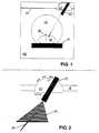
- FIG. 1shows the front of a computer tomograph with a housing 10 and a gantry 12.
- a couch 14 on which a patient 16 is indicatedis also seen.
- the couch 14can be moved linearly into the computer tomograph.
- a horizontal guide 18is arranged above the gantry 12, on which a slide 20 is displaceable.
- the carriage 20can be locked in any position on the guide 18.
- the carriage 20pivotally supports a rod-shaped laser device 22, which projects a cross, for example.
- the laser device 22generates two lines perpendicular to one another, one of which in a transverse plane, which is designated by 24 in FIG. 2, and the other in a sagittal plane, which is shown in FIG. 2 is denoted by 24, runs.
- the two radiation levels mentionedextend at an angle to the sagittal plane of the patient, which is described as 26 in FIG. 1.
- FIG. 4shows an alternative carriage 20 'with a laser device 22' which is mounted on the carriage 20 'at 30 so as to be pivotable about a horizontal axis.
- the laser device 22can be locked in any angular position.
- a tipis provided on the laser device 22 ′ at the rear end 32, which interacts with a scale 34 on the slide 20 ′. The size of the angular position of the laser device 22 ′ can be read off the scale.
- the insertion pointfor example of a biopsy needle on the patient's body, is determined using the CT and marked on the body by the doctor.
- the doctoralso knows from the CT images the angle at which the instrument must be held or guided in order to guide the instrument to the patient's target site without impairing bones or organs.
- the doctorsets the angular position by setting and locking the laser device 22 or 22 'to the predetermined angle.
- the patientwas so far out of the computer tomograph extended until the marking made on the body coincides with the transverse plane 24 of the laser device 22.
- the carriage 20 or 20 'isthen moved along the guide 18 until the sagittal plane 24 also passes through the marking. Now the instrument is to be held and guided so that the cross of the laser device 22 or 22 'is projected at the rear end.
- FIG. 4indicates how the target device shown in FIGS. 1 to 3 can be implemented mechanically.
- the guide 18is formed by a rail 40, on which a carriage 42 is precisely guided in a suitable manner. This tour will not be discussed in detail.
- arms 44, 46 projecting perpendicularly theretoare attached, which have locking bolts 48 and 50 on the outside.
- the locking boltsare loaded by springs, which bring them back to their original position when they are pulled out by hand.
- a holding plate 52 or 54is attached to the housing 10 on both sides of the gantry 12. 3, the holding plate 52 or 54 is shown once in a side view (as fastened to the housing of the CT) and once in a front view. Every plate 52 and 54 is provided with two clamping devices 56 and 58 for attachment to the housing with a corresponding adjustment of the parallelism.
- a guide bar 60 or 62is arranged, which is designed like a ramp in the upper region and both increases gradually in height and gradually increases in width. This ramp-like section is used for insertion into the complementary profile (not shown) of the arms 44, 46.
- a roller 72, 74is rotatably mounted in the upper area to the side of the strips 60, 62. It serves to facilitate the insertion of the profile of the arms 44, 46 into the holder.
Landscapes
- Health & Medical Sciences (AREA)
- Life Sciences & Earth Sciences (AREA)
- Engineering & Computer Science (AREA)
- Medical Informatics (AREA)
- Surgery (AREA)
- Animal Behavior & Ethology (AREA)
- Public Health (AREA)
- Heart & Thoracic Surgery (AREA)
- Nuclear Medicine, Radiotherapy & Molecular Imaging (AREA)
- Molecular Biology (AREA)
- Pathology (AREA)
- General Health & Medical Sciences (AREA)
- Biomedical Technology (AREA)
- Veterinary Medicine (AREA)
- Physics & Mathematics (AREA)
- Biophysics (AREA)
- High Energy & Nuclear Physics (AREA)
- Optics & Photonics (AREA)
- Radiology & Medical Imaging (AREA)
- Apparatus For Radiation Diagnosis (AREA)
Abstract
Description
Translated fromGermanDie Erfindung bezieht sich auf eine Zielvorrichtung für das geradlinige Einführen eines Instruments in einen menschlichen Körper nach dem Oberbegriff des Patentanspruchs 1.The invention relates to a target device for the straight insertion of an instrument into a human body according to the preamble of patent claim 1.
Bei der Biopsie werden Nadeln in den Körper des Patienten gestochen, um aus einer bestimmten Körperstelle Gewebsproben zu entnehmen oder Instrumente zu dieser Stelle zu führen. Es ist bekannt, die Zielstelle mit Hilfe eines Computertomographen (CT) zu bestimmen. Er erzeugt ein virtuelles Schnittbild des Körpers in verschiedenen Schnittebenen. Nach dem CT-Bild kann die Zielstelle ermittelt werden und die Einstichstelle und der Verlauf des Stichkanals bestimmt werden. Wenn der Einstich nicht senkrecht von oben oder waagerecht von der Seite erfolgen kann, weil Organe oder Knochen im Wege sind, ist es schwierig, den durch das CT-Bild ermittelten Einstichwinkel in die Realität zu übertragen und die lange Nadel im richtigen Winkel zu führen. Findet eine Abweichung vom richtigen Winkel statt, wird die Zielstelle verpaßt und die Prozedur muß wiederholt werden.During the biopsy, needles are inserted into the patient's body in order to take tissue samples from a specific part of the body or to guide instruments to this point. It is known to determine the target location using a computer tomograph (CT). It creates a virtual sectional image of the body in different sectional planes. After the CT image, the target site can be determined and the puncture site and the course of the branch canal can be determined. If the puncture cannot be made vertically from above or horizontally from the side because organs or bones are in the way, it is difficult to translate the puncture angle determined by the CT image into reality and to guide the long needle at the correct angle. If there is a deviation from the correct angle, the target location is missed and the procedure must be repeated.
Der Erfindung liegt daher die Aufgabe zugrunde, eine Zielvorrichtung für das geradlinige Einführen eines Instruments in einen menschlichen Körper zu schaffen, mit der auf einfache Weise das Instrument im vorgegebenen Winkel zur vorbestimmten Zielstelle geführt werden kann.The invention is therefore based on the object of providing a target device for the straight-line insertion of an instrument into a human body, with which the instrument can be guided in a simple manner at a predetermined angle to the predetermined target location.
Diese Aufgabe wird durch die Merkmale des Patentanspruchs 1 gelöst.This object is achieved by the features of patent claim 1.
Erfindungsgemäß ist ein Schlitten oberhalb der Gantry (Einführöffnung) des Computertomographen entlang einer horizontalen Führung, vorzugsweise entlang einer Transversalebene, verstellbar geführt und an einem beliebigen Punkt feststellbar. Der Schlitten lagert eine Laservorrichtung um eine horizontale Achse. Die Laservorrichtung erzeugt eine Zielmarkierung, zum Beispiel in Form eines Punktes oder eines Kreuzes im Raum. Bei der Verschwenkung der Laservorrichtung wird der Laserstrahl in einer vertikalen Ebene entsprechend mit verschwenkt. Am Schlitten ist außerdem eine Winkelskala angebracht, an der der Schwenkwinkel der Laservorrichtung abgelesen werden kann. Es versteht sich, daß auch bei einem beliebigen Schwenkwinkel die Laservorrichtung arretiert werden kann.According to the invention, a slide is adjustably guided above the gantry (insertion opening) of the computer tomograph along a horizontal guide, preferably along a transverse plane, and on any one Point ascertainable. The carriage supports a laser device around a horizontal axis. The laser device creates a target mark, for example in the form of a point or a cross in space. When the laser device is pivoted, the laser beam is also pivoted accordingly in a vertical plane. An angle scale is also attached to the slide, on which the swivel angle of the laser device can be read. It goes without saying that the laser device can also be locked at any pivoting angle.
Die Laservorrichtung ist vorzugsweise eine Einheit und schwenkbar am Schlitten angebracht. Sie projiziert vorzugsweise ein Linienkreuz.The laser device is preferably a unit and is pivotally attached to the carriage. It projects preferably a line cross.
Alternativ kann ein Kreuz auch dadurch projiziert werden, daß ein Linienlaser raumfest angebracht, dessen Strahlebene in einer Transversalebene bezüglich des Patientenkörpers verläuft. Ein zweiter Linienlaser, dessen Strahlebene in der Nullstellung in der Sagittalebene verläuft, ist am Schlitten schwenkbar angebracht.Alternatively, a cross can also be projected in that a line laser is fixed in space, the beam plane of which extends in a transverse plane with respect to the patient's body. A second line laser, whose beam level runs in the sagittal plane in the zero position, is pivotably attached to the slide.
Die Führung ist vorzugsweise am Gehäuse des Computertomographen angebracht, beispielsweise in Form einer horizontalen Schiene, die oberhalb der Gantry angebracht ist. Die Schiene kann mit senkrecht dazu verlaufenden Armen versehen sein, die mit länglichen Halteprofilen beidseits der Gantry zusammenwirken.The guide is preferably attached to the housing of the computer tomograph, for example in the form of a horizontal rail which is attached above the gantry. The Rail can be provided with arms running perpendicular to it, which interact with elongated holding profiles on both sides of the gantry.
Der Patient wird auf einer entlang einer Führung verfahrbaren Liege in den Computertomographen hinein und aus diesem herausbewegt. Beim Start befindet sich der die Laservorrichtung lagernde Verfahrschlitten in der Mitte der Führung bzw. der Schiene und die Laservorrichtung ist in Nullstellung senkrecht nach unten gerichtet, wobei in dieser Position z.B. ein Kreuz senkrecht von oben auf den Patienten projiziert wird. Alternativ kann auch ein Punkt projiziert werden. Die Sagittallinie verläuft bekanntlich in der Mitte der Liege und des CT und die Transversallinie der Laservorrichtung verläuft parallel zur Scanebene des CT in einem festen aber bekannten Abstand. Nach diesen Linien kann der Patient auf der Liege ausgerichtet werden. Der Patient wird auf der Linie mit der zu scannenden Körperpartie in die Transversalebene gefahren und markiert. Diese Markierung dient dem äußerlich wiedererkennbaren Bezug von Scanebene und Patientenkörper. Dann wird der Patient gescannt. Der Arzt wählt aus den CT-Bildern die geeignete Scanebene für die Intervention aus. Unter Berücksichtigung des erwähnten Abstands wird der Patient mit der Liege so weit herausgefahren, bis die gewählte Scanebene in der Ebene der Transversallinie liegt.The patient is moved into and out of the computer tomograph on a couch that can be moved along a guide. At the start, the traversing carriage supporting the laser device is located in the middle of the guide or rail and the laser device is directed vertically downwards in the zero position, in which position, for example, a cross is projected onto the patient vertically from above. Alternatively, a point can be projected. As is known, the sagittal line runs in the middle of the bed and the CT and the transverse line of the laser device runs parallel to the scanning plane of the CT at a fixed but known distance. The patient can be aligned on the couch along these lines. The patient is moved on the line with the body part to be scanned into the transverse plane and marked. This marking serves the externally recognizable reference of the scan plane and patient body. Then the patient is scanned. The doctor selects the appropriate scan plane for the intervention from the CT images. Taking into account the distance mentioned, the patient is extended with the couch until the selected scan level lies in the plane of the transverse line.
Der Arzt bestimmt die Einstichstelle und den Einstichwinkel aus den CT-Bildern. Er legt die seitliche Lage der Einstichstelle nach markanten anatomischen Merkmalen des Patienten fest und markiert die Einstichstelle. Anschließend schwenkt er die Laservorrichtung in die festgelegte Winkelstellung, indem er zum Beispiel eine Marke an der stabförmigen Laservorrichtung auf den gewählten Winkel bringt und anschließend die Laservorrichtung arretiert. Anschließend wird der Verfahrschlitten mit dem geschwenkten Laser so lange seitwärts gefahren, bis das Laserkreuz die Markierung der Einstichstelle trifft. Das Instrument, zum Beispiel eine Nadel, muß so auf die Einstichstelle gesetzt werden, daß ihre Rückseite vom Laserkreuz getroffen wird. Ist das der Fall, ist die Nadel im vorher festgelegten Winkel auf die Zielstelle ausgerichtet.The doctor determines the injection site and the injection angle from the CT images. He determines the lateral position of the puncture site according to the patient's distinctive anatomical features and marks the puncture site. He then pivots the laser device into the defined angular position, for example by bringing a mark on the rod-shaped laser device to the selected angle and then locking the laser device. The traversing carriage is then moved sideways with the swiveled laser until the laser cross meets the marking of the puncture site. The instrument, for example a needle, must be placed on the puncture site in such a way that its back is hit by the laser cross. If this is the case, the needle is aligned with the target point at a predetermined angle.
Es versteht sich, daß auch drei Systeme der beschriebenen Art verwendet werden können, bei denen eine Führung horizontal und zwei senkrecht seitlich der Gantry angebracht sind, um Schwenkwinkel größer als 45° zu verwirklichen.It goes without saying that three systems of the type described can also be used, in which one guide is mounted horizontally and two perpendicularly to the side of the gantry, in order to achieve swivel angles greater than 45 °.
Die Erfindung wird nachfolgend anhand von Zeichnungen näher erläutert.
- Fig. 1
- zeigt schematisch die Frontansicht eines Computertomographen mit einer Vorrichtung nach der Erfindung.
- Fig. 2
- zeigt eine Einzelheit der Vorrichtung nach Fig. 1.
- Fig. 3
- zeigt detailliert ein Teil der Vorrichtung nach Fig. 1.
- Fig. 4
- zeigt eine Einzelheit der Vorrichtung nach Fig. 2.
- Fig. 1
- shows schematically the front view of a computer tomograph with a device according to the invention.
- Fig. 2
- shows a detail of the device of FIG. 1st
- Fig. 3
- shows in detail a part of the device of FIG. 1st
- Fig. 4
- shows a detail of the device of FIG. 2nd
In Fig. 1 ist die Frontseite eines Computertomographen dargestellt mit einem Gehäuse 10 und einer Gantry 12. Man erkennt außerdem eine Liege 14, auf der ein Patient 16 angedeutet liegt. Die Liege 14 ist linear verfahrbar in den Computertomographen hinein. Oberhalb der Gantry 12 ist eine horizontale Führung 18 angeordnet, an der ein Schlitten 20 verschiebbar ist. Der Schlitten 20 kann in einer beliebigen Stellung an der Führung 18 arretiert werden. Der Schlitten 20 lagert schwenkbar eine stabförmige Laservorrichtung 22, die zum Beispiel ein Kreuz projiziert. Zu diesem Zweck erzeugt die Laservorrichtung 22 zwei senkrecht zueinander stehende Linien, von denen die eine in einer Transversalebene, die in Fig. 2 mit 24 bezeichnet ist und die andere in einer Sagittalebene, die in Fig. 2 mit 24 bezeichnet ist, verläuft. Wie aus Fig. 1 zu erkennen, erstrecken sich beide genannten Strahlungsebenen in einem Winkel zur Sagittalebene des Patienten, die in Fig. 1 mit 26 beschrieben ist.1 shows the front of a computer tomograph with a
In Fig. 4 ist ein alternativer Schlitten 20' dargestellt mit einer Laservorrichtung 22', die bei 30 um eine horizontale Achse am Schlitten 20' schwenkbar gelagert ist. In beliebiger Winkelstellung kann jedoch eine Arretierung der Laservorrichtung 22 vorgenommen werden. An der Laservorrichtung 22' ist eine Spitze am hinteren Ende 32 vorgesehen, die mit einer Skala 34 am Schlitten 20' zusammenwirkt. An der Skala ist die Größe der Winkelstellung der Laservorrichtung 22' ablesbar.4 shows an alternative carriage 20 'with a laser device 22' which is mounted on the carriage 20 'at 30 so as to be pivotable about a horizontal axis. However, the
Wie schon erwähnt, wird die Einführstelle zum Beispiel einer Biopsienadel am Patientenkörper mit Hilfe des CT ermittelt und vom Arzt am Körper markiert. Dem Arzt ist ferner durch die CT-Bilder der Winkel bekannt, in dem das Instrument gehalten bzw. geführt werden muß, um ohne Beeinträchtigung von Knochen oder Organen das Instrument zur Zielstelle des Patienten zu führen. Die Winkelstellung stellt der Arzt dadurch ein, daß er die Laservorrichtung 22 bzw. 22' auf den vorgegebenen Winkel einstellt und arretiert. Zuvor war der Patient so weit aus dem Computertomographen herausgefahren, bis die am Körper vorgenommene Markierung mit der Transversalebene 24 der Laservorrichtung 22 zusammenfällt. Anschließend wird der Schlitten 20 bzw. 20' so weit entlang der Führung 18 verfahren, bis auch die Sagittalebene 24 durch die Markierung geht. Nunmehr ist das Instrument so zu halten und zu führen, daß am hinteren Ende das Kreuz der Laservorrichtung 22 bzw. 22' projiziert wird.As already mentioned, the insertion point, for example of a biopsy needle on the patient's body, is determined using the CT and marked on the body by the doctor. The doctor also knows from the CT images the angle at which the instrument must be held or guided in order to guide the instrument to the patient's target site without impairing bones or organs. The doctor sets the angular position by setting and locking the
In Fig. 4 ist angedeutet, wie die gezeigte Zielvorrichtung nach den Figuren 1 bis 3 mechanisch verwirklicht werden kann. Die Führung 18 wird von einer Schiene 40 gebildet, an der ein Schlitten 42 in geeigneter Weise präzise geführt wird. Auf diese Führung wird im einzelnen nicht eingegangen. An den Enden der Schiene 40 sind senkrecht dazu abstehend Arme 44, 46 angebracht, die an der Außenseite Rastbolzen 48 bzw. 50 aufweisen. Die Rastbolzen sind von Federn beaufschlagt, wodurch sie in die Ursprungsstellung zurückgebracht werden, wenn sie von Hand herausgezogen werden.FIG. 4 indicates how the target device shown in FIGS. 1 to 3 can be implemented mechanically. The
Beidseits der Gantry 12 ist am Gehäuse 10 eine Halteplatte 52 bzw. 54 angebracht. In Fig. 3 ist die Halteplatte 52 bzw. 54 einmal in Seitenansicht (wie am Gehäuse des CT befestigt) und einmal in Frontansicht gezeigt. Jede Platte 52 bzw. 54 ist mit zwei Klemmvorrichtung 56 bzw. 58 versehen zur Anbringung am Gehäuse mit einer entsprechenden Einstellung der Parallelität. An der Außenseite der Platte 52, 54 ist eine Führungsleiste 60 bzw. 62 angeordnet, die im oberen Bereich rampenartig ausgebildet ist und sowohl in der Höhe allmählich ansteigt als auch in der Breite allmählich größer wird. Dieser rampenartige Abschnitt dient zum Einführen in das nicht gezeigte komplementäre Profil der Arme 44, 46. An der Außenseite im unteren Bereich ist ferner eine Aufnahme 64 bzw. 66 für die Arme 48, 50 vorgesehen. In der Leiste 60, 62 befindet sich eine Bohrung 68 bzw. 70 für den Rastbolzen 48, 50. Dadurch können die Arme 44, 46 lagerichtig positioniert werden. Dadurch erhält auch die Führung 18 eine präzise Lage im Raum. Schließlich ist im oberen Bereich seitlich der Leisten 60, 62 eine Rolle 72, 74 drehbar gelagert. Sie dient zum erleichterten Einführen des Profils der Arme 44, 46 in die Halterung.A holding
Claims (9)
Translated fromGermanApplications Claiming Priority (2)
| Application Number | Priority Date | Filing Date | Title |
|---|---|---|---|
| DE19502356 | 1995-01-26 | ||
| DE19502356ADE19502356A1 (en) | 1995-01-26 | 1995-01-26 | Target device for the straight insertion of an instrument into a human body |
Publications (2)
| Publication Number | Publication Date |
|---|---|
| EP0723763A1true EP0723763A1 (en) | 1996-07-31 |
| EP0723763B1 EP0723763B1 (en) | 1999-05-26 |
Family
ID=7752350
Family Applications (1)
| Application Number | Title | Priority Date | Filing Date |
|---|---|---|---|
| EP96100001AExpired - LifetimeEP0723763B1 (en) | 1995-01-26 | 1996-01-02 | Aiming device for linearly introducing an instrument into a human body |
Country Status (3)
| Country | Link |
|---|---|
| US (1) | US5707360A (en) |
| EP (1) | EP0723763B1 (en) |
| DE (2) | DE19502356A1 (en) |
Cited By (2)
| Publication number | Priority date | Publication date | Assignee | Title |
|---|---|---|---|---|
| GB2324736A (en)* | 1997-05-02 | 1998-11-04 | Laser Applikationan Gmbh | Targetting device for straight-lined introduction of an instrument into the body |
| CN109173089A (en)* | 2018-09-20 | 2019-01-11 | 成都真实维度科技有限公司 | A kind of device using laser aiming radioactive prospecting instrument tumour |
Families Citing this family (16)
| Publication number | Priority date | Publication date | Assignee | Title |
|---|---|---|---|---|
| US6096049A (en)* | 1998-07-27 | 2000-08-01 | Minrad Inc. | Light guiding device and method |
| AU2004200685B2 (en)* | 1998-07-27 | 2006-02-09 | Minrad Inc | Light Guiding Device and Method |
| US6154522A (en)* | 1999-02-11 | 2000-11-28 | Mcdonnell Douglas Corporation | Method, system and apparatus for aiming a device emitting a radiant beam |
| DE20002604U1 (en)* | 2000-02-15 | 2001-06-21 | Ao Entwicklungsinstitut, Davos | Laser pointer |
| DE10015510C2 (en)* | 2000-03-30 | 2002-01-17 | Siemens Ag | Medical device with a drive device for a needle |
| DE10258534A1 (en)* | 2002-12-14 | 2004-07-08 | Lam, Hoang van, Dr.med. | Device and method for manual guiding of stick-shaped object to pre-determined spot inside body of patient |
| DE102004052281B4 (en)* | 2004-10-27 | 2012-07-05 | Siemens Ag | Adjustment device and adjustment method for a tomography device |
| US7147371B2 (en)* | 2004-12-10 | 2006-12-12 | Joseph Hecker | Laser guides for X-ray device |
| DE102006004692A1 (en) | 2006-01-31 | 2007-08-09 | Siemens Ag | An imaging medical device and method for such a device |
| DE102007057493B4 (en) | 2007-11-29 | 2017-07-13 | Siemens Healthcare Gmbh | X-ray system with improved planning of a needle path |
| ES2676718T3 (en)* | 2012-12-21 | 2018-07-24 | Alcon Research, Ltd. | Cassette clamping system |
| KR101798939B1 (en)* | 2015-09-08 | 2017-11-17 | 삼성전자주식회사 | X-ray image apparatus and control method for the same |
| US10881362B2 (en)* | 2018-11-20 | 2021-01-05 | General Electric Company | Systems for laser alignment |
| CN111544097A (en)* | 2020-05-24 | 2020-08-18 | 郭春梅 | Stereotactic device and stereotactic method |
| DE202021106072U1 (en) | 2021-11-05 | 2022-01-13 | Itp Innovative Tomography Products Gmbh | Auxiliary device for the introduction of a surgical needle instrument |
| CN115670656A (en)* | 2022-09-28 | 2023-02-03 | 佗道医疗科技有限公司 | Laser Executive Navigation System |
Citations (6)
| Publication number | Priority date | Publication date | Assignee | Title |
|---|---|---|---|---|
| FR2284338A1 (en)* | 1974-09-11 | 1976-04-09 | Siemens Ag | DEVICE FOR PERFORMING PUNCTIONS IN ORGANS, VESSELS OR OTHER SIMILAR PARTS INTERNAL TO THE HUMAN BODY |
| US4246486A (en)* | 1978-04-20 | 1981-01-20 | Siemens Aktiengesellschaft | X-ray photography device |
| US4629989A (en)* | 1983-11-10 | 1986-12-16 | General Electric Company | Patient alignment system for NMR studies |
| US4651732A (en)* | 1983-03-17 | 1987-03-24 | Frederick Philip R | Three-dimensional light guidance system for invasive procedures |
| WO1988008282A1 (en)* | 1987-04-27 | 1988-11-03 | Elekta Instrument Ab | Apparatus for marking an operating site |
| US5320111A (en)* | 1992-02-07 | 1994-06-14 | Livingston Products, Inc. | Light beam locator and guide for a biopsy needle |
Family Cites Families (14)
| Publication number | Priority date | Publication date | Assignee | Title |
|---|---|---|---|---|
| DE330092C (en)* | 1912-08-08 | 1920-12-07 | Robert Henry Clarke | Device for location determination for operational purposes |
| US2455928A (en)* | 1944-07-29 | 1948-12-14 | Hawks Thomas Richard | X-ray tube sighting device |
| DE2134122C3 (en)* | 1971-07-08 | 1984-05-30 | Siemens AG, 1000 Berlin und 8000 München | X-ray machine for skull examinations |
| US3748041A (en)* | 1972-01-31 | 1973-07-24 | American Optical Corp | Laser beam attitude control device |
| US4139776A (en)* | 1977-09-22 | 1979-02-13 | Cgr Medical Corporation | System for circular and complex tomography |
| US4538289A (en)* | 1981-12-28 | 1985-08-27 | General Electric Company | Reflective alignment light for computerized tomography |
| US4836671A (en)* | 1985-04-08 | 1989-06-06 | Charles Lescrenier | Locating device |
| JPS63229250A (en)* | 1987-03-13 | 1988-09-26 | Kitamura Mach Co Ltd | Machining center |
| US5188110A (en)* | 1988-07-13 | 1993-02-23 | Kabushiki Kaisha Toshiba | Method and apparatus for setting multi-slice imaging conditions in computed tomographic imaging systems |
| US4930525A (en)* | 1989-03-28 | 1990-06-05 | Palestrant Aubrey M | Method for performing C.T. guided drainage and biopsy procedures |
| US5308352A (en)* | 1989-11-17 | 1994-05-03 | Koutrouvelis Panos G | Stereotactic device |
| DE9218321U1 (en)* | 1992-01-28 | 1993-12-09 | Grönemeyer, Dietrich H. W., Dr.med., 45468 Mülheim | Computer tomograph |
| US5394616A (en)* | 1993-03-05 | 1995-03-07 | Claxton; Douglas | Laser positioning device |
| US5367779A (en)* | 1993-08-18 | 1994-11-29 | Cheng Long Plastic Co., Ltd. | Laser marker |
- 1995
- 1995-01-26DEDE19502356Apatent/DE19502356A1/ennot_activeCeased
- 1996
- 1996-01-02DEDE59601962Tpatent/DE59601962D1/ennot_activeExpired - Fee Related
- 1996-01-02EPEP96100001Apatent/EP0723763B1/ennot_activeExpired - Lifetime
- 1996-01-19USUS08/591,418patent/US5707360A/ennot_activeExpired - Fee Related
Patent Citations (6)
| Publication number | Priority date | Publication date | Assignee | Title |
|---|---|---|---|---|
| FR2284338A1 (en)* | 1974-09-11 | 1976-04-09 | Siemens Ag | DEVICE FOR PERFORMING PUNCTIONS IN ORGANS, VESSELS OR OTHER SIMILAR PARTS INTERNAL TO THE HUMAN BODY |
| US4246486A (en)* | 1978-04-20 | 1981-01-20 | Siemens Aktiengesellschaft | X-ray photography device |
| US4651732A (en)* | 1983-03-17 | 1987-03-24 | Frederick Philip R | Three-dimensional light guidance system for invasive procedures |
| US4629989A (en)* | 1983-11-10 | 1986-12-16 | General Electric Company | Patient alignment system for NMR studies |
| WO1988008282A1 (en)* | 1987-04-27 | 1988-11-03 | Elekta Instrument Ab | Apparatus for marking an operating site |
| US5320111A (en)* | 1992-02-07 | 1994-06-14 | Livingston Products, Inc. | Light beam locator and guide for a biopsy needle |
Cited By (5)
| Publication number | Priority date | Publication date | Assignee | Title |
|---|---|---|---|---|
| GB2324736A (en)* | 1997-05-02 | 1998-11-04 | Laser Applikationan Gmbh | Targetting device for straight-lined introduction of an instrument into the body |
| FR2762775A1 (en)* | 1997-05-02 | 1998-11-06 | Laser Applikationan Gmbh | SIGHTING DEVICE FOR THE STRAIGHT INTRODUCTION OF AN INSRUMENT INTO A HUMAN BODY |
| GB2324736B (en)* | 1997-05-02 | 2001-02-28 | Laser Applikationan Gmbh | Targeting device for the straight-lined introduction of an instrument into a human body |
| CN109173089A (en)* | 2018-09-20 | 2019-01-11 | 成都真实维度科技有限公司 | A kind of device using laser aiming radioactive prospecting instrument tumour |
| CN109173089B (en)* | 2018-09-20 | 2024-02-13 | 成都真实维度科技有限公司 | Device for guiding radioactive particles to implant tumor by laser |
Also Published As
| Publication number | Publication date |
|---|---|
| DE19502356A1 (en) | 1996-08-08 |
| US5707360A (en) | 1998-01-13 |
| EP0723763B1 (en) | 1999-05-26 |
| DE59601962D1 (en) | 1999-07-01 |
Similar Documents
| Publication | Publication Date | Title |
|---|---|---|
| EP0723763B1 (en) | Aiming device for linearly introducing an instrument into a human body | |
| DE69817368T2 (en) | DEVICE FOR GUIDING PERCUTANEOUS DEVICES BY COMPUTER TOMOGRAPH | |
| DE69837781T2 (en) | Target device for implant devices | |
| DE69531803T2 (en) | Guide system for milling bones | |
| DE69100142T2 (en) | Mammography device with needle holder. | |
| DE3717871C3 (en) | Method and device for reproducible visual representation of a surgical intervention | |
| DE3930022C2 (en) | Panoramic x-ray device for the optional production of dental panoramic images and skull images | |
| DE19524951C2 (en) | Device for marking an area of a patient to be irradiated | |
| DE102006059707B3 (en) | Device for radiotherapy under image monitoring | |
| DE102008013615A1 (en) | Method and marking device for marking a guide line of a penetration instrument, control device and recording system | |
| EP0297354B1 (en) | Biopsy device for an x-ray apparatus | |
| DE29521736U1 (en) | Device for the mechanical alignment of bone screws in a medullary nail | |
| DE2608461A1 (en) | X-RAY EXAMINER | |
| DE4421316A1 (en) | Device for positioning and marking a patient on diagnostic devices, e.g. before and after fluoroscopy in a computer tomograph | |
| EP0606548A1 (en) | Apparatus for extracorporal therapy | |
| DE19530013C1 (en) | Correcting position of target e.g. tumour in target region of radiation treatment device | |
| DE102005030285B4 (en) | Computed tomography device and method for a computed tomography device with a marking means for positionally accurate marking of an intervention position by means of a laser beam on an object to be examined | |
| DE2953317A1 (en) | Tomographic method and apparatus | |
| EP0986326A1 (en) | In vivo detection of langer's lines | |
| EP2919654B1 (en) | Radiology workstation | |
| EP1675520A1 (en) | Device for placing instruments or implants in body organs | |
| DE29502525U1 (en) | Target device for the straight insertion of an instrument into a human body | |
| EP3622908B1 (en) | Alignment element for aligning a needle guide; alignment arrangement; guiding arrangement; treatment arrangement and method | |
| DE19511106C1 (en) | Lithotripsy device | |
| DE2501436A1 (en) | Radiodiagnostic and cytological sampling appts. - to detect malignant tumours in the female breast |
Legal Events
| Date | Code | Title | Description |
|---|---|---|---|
| PUAI | Public reference made under article 153(3) epc to a published international application that has entered the european phase | Free format text:ORIGINAL CODE: 0009012 | |
| AK | Designated contracting states | Kind code of ref document:A1 Designated state(s):DE FR GB NL SE | |
| 17P | Request for examination filed | Effective date:19961125 | |
| 17Q | First examination report despatched | Effective date:19970905 | |
| GRAG | Despatch of communication of intention to grant | Free format text:ORIGINAL CODE: EPIDOS AGRA | |
| GRAG | Despatch of communication of intention to grant | Free format text:ORIGINAL CODE: EPIDOS AGRA | |
| GRAH | Despatch of communication of intention to grant a patent | Free format text:ORIGINAL CODE: EPIDOS IGRA | |
| GRAH | Despatch of communication of intention to grant a patent | Free format text:ORIGINAL CODE: EPIDOS IGRA | |
| GRAA | (expected) grant | Free format text:ORIGINAL CODE: 0009210 | |
| AK | Designated contracting states | Kind code of ref document:B1 Designated state(s):DE FR GB NL SE | |
| ET | Fr: translation filed | ||
| GBT | Gb: translation of ep patent filed (gb section 77(6)(a)/1977) | Effective date:19990526 | |
| REF | Corresponds to: | Ref document number:59601962 Country of ref document:DE Date of ref document:19990701 | |
| PG25 | Lapsed in a contracting state [announced via postgrant information from national office to epo] | Ref country code:GB Free format text:LAPSE BECAUSE OF NON-PAYMENT OF DUE FEES Effective date:20000102 | |
| PG25 | Lapsed in a contracting state [announced via postgrant information from national office to epo] | Ref country code:SE Free format text:LAPSE BECAUSE OF NON-PAYMENT OF DUE FEES Effective date:20000103 | |
| PLBE | No opposition filed within time limit | Free format text:ORIGINAL CODE: 0009261 | |
| STAA | Information on the status of an ep patent application or granted ep patent | Free format text:STATUS: NO OPPOSITION FILED WITHIN TIME LIMIT | |
| 26N | No opposition filed | ||
| GBPC | Gb: european patent ceased through non-payment of renewal fee | Effective date:20000102 | |
| EUG | Se: european patent has lapsed | Ref document number:96100001.5 | |
| PGFP | Annual fee paid to national office [announced via postgrant information from national office to epo] | Ref country code:NL Payment date:20010131 Year of fee payment:6 | |
| PGFP | Annual fee paid to national office [announced via postgrant information from national office to epo] | Ref country code:DE Payment date:20010220 Year of fee payment:6 | |
| PG25 | Lapsed in a contracting state [announced via postgrant information from national office to epo] | Ref country code:FR Free format text:LAPSE BECAUSE OF NON-PAYMENT OF DUE FEES Effective date:20010928 | |
| REG | Reference to a national code | Ref country code:FR Ref legal event code:ST | |
| PG25 | Lapsed in a contracting state [announced via postgrant information from national office to epo] | Ref country code:NL Free format text:LAPSE BECAUSE OF NON-PAYMENT OF DUE FEES Effective date:20020801 Ref country code:DE Free format text:LAPSE BECAUSE OF NON-PAYMENT OF DUE FEES Effective date:20020801 | |
| NLV4 | Nl: lapsed or anulled due to non-payment of the annual fee | Effective date:20020801 | |
| PG25 | Lapsed in a contracting state [announced via postgrant information from national office to epo] | Ref country code:FR Free format text:LAPSE BECAUSE OF NON-PAYMENT OF DUE FEES Effective date:20000131 |