EP0723346A1 - Transmission system for digital speech signals and device for coding/decoding to be used in the system - Google Patents
Transmission system for digital speech signals and device for coding/decoding to be used in the systemDownload PDFInfo
- Publication number
- EP0723346A1 EP0723346A1EP95203454AEP95203454AEP0723346A1EP 0723346 A1EP0723346 A1EP 0723346A1EP 95203454 AEP95203454 AEP 95203454AEP 95203454 AEP95203454 AEP 95203454AEP 0723346 A1EP0723346 A1EP 0723346A1
- Authority
- EP
- European Patent Office
- Prior art keywords
- compression
- decompression
- frames
- coding
- voice signals
- Prior art date
- Legal status (The legal status is an assumption and is not a legal conclusion. Google has not performed a legal analysis and makes no representation as to the accuracy of the status listed.)
- Withdrawn
Links
- 230000005540biological transmissionEffects0.000titleclaimsdescription21
- 238000007906compressionMethods0.000claimsabstractdescription42
- 230000006835compressionEffects0.000claimsabstractdescription39
- 230000006837decompressionEffects0.000claimsabstractdescription31
- 239000002131composite materialSubstances0.000abstract1
- 238000013523data managementMethods0.000abstract1
- 238000012360testing methodMethods0.000description12
- 101150037339Cavin1 geneProteins0.000description10
- 230000001960triggered effectEffects0.000description8
- 102100036514Amyloid-beta A4 precursor protein-binding family A member 1Human genes0.000description7
- 101710093637Amyloid-beta A4 precursor protein-binding family A member 1Proteins0.000description7
- 238000000034methodMethods0.000description6
- 238000004891communicationMethods0.000description5
- 102100032306Aurora kinase BHuman genes0.000description3
- 101000798306Homo sapiens Aurora kinase BProteins0.000description3
- 101100381534Saccharomyces cerevisiae (strain ATCC 204508 / S288c) BEM2 geneProteins0.000description3
- 238000003780insertionMethods0.000description3
- 230000037431insertionEffects0.000description3
- 238000005259measurementMethods0.000description3
- 238000006243chemical reactionMethods0.000description2
- 230000000694effectsEffects0.000description2
- 238000007726management methodMethods0.000description2
- 238000012545processingMethods0.000description2
- 230000011664signalingEffects0.000description2
- 230000001629suppressionEffects0.000description2
- 238000012550auditMethods0.000description1
- 230000001186cumulative effectEffects0.000description1
- 230000001934delayEffects0.000description1
- 238000012217deletionMethods0.000description1
- 230000037430deletionEffects0.000description1
- 238000010586diagramMethods0.000description1
- 230000006870functionEffects0.000description1
- 238000012552reviewMethods0.000description1
- 230000033764rhythmic processEffects0.000description1
- 238000005070samplingMethods0.000description1
Images


Classifications
- H—ELECTRICITY
- H04—ELECTRIC COMMUNICATION TECHNIQUE
- H04J—MULTIPLEX COMMUNICATION
- H04J3/00—Time-division multiplex systems
- H04J3/18—Time-division multiplex systems using frequency compression and subsequent expansion of the individual signals
Definitions
- the inventionalso relates to a coding-decoding device for such a system.
- the application envisaged for such a systemis to transmit telephone communications over a digital data network. This transmission of telephone communications can only be done, for reasons of economy of speed to be transmitted, in compressed form.
- the compression and decompression processesintroduce a delay to which is added the transmission delay over the digital network.
- this cumulative timedoes not must not cause a delay that exceeds 200 ms, otherwise the subscribers experience significant discomfort in their telephone communications.
- the inventionproposes a system in which measures have been taken to avoid too long a delay time without taking account of the algorithm used.
- the compression and decompression processesare in principle executed by signal processors which are, in general, sequential processing devices, the priority proposition of the compression device therefore does not introduce any delay. additional.
- the reference CArepresents the telephone handset of a first subscriber attached to one end A of a transmission system according to the invention.
- Analog voice signals from the CA handsetare received at an AR1A receive port and voice signals to be output from the CA handset are supplied to an AE1A transmit port.
- the reference CBis the reference of the handset of a second subscriber, attached to one end B of said system via access BR1A and BE1A.
- the voice signals of the two subscribers attached to the ends A and Bare processed respectively by coding-decoding devices CVA and CVB.
- These CVA and CVB devicesrespectively comprise compression-decompression circuits formed by a CPRSSA compression unit and a DECPRSSA decompression unit for the CVA device and by a CPRSSB compression unit and a DECPRSSB decompression unit for the CVB system.
- the digital voice signals, compressed by the CPRSSA deviceare made available to an AE2N access of the CVA device and the digital voice signals, compressed by the CPRSSB device, are made available to a BE2N access of the CVB device.
- These voice signals compressed by the CPRSSA and CPRSSB devicesare respectively transmitted via the network to the BR2N and AR2N ports to be decompressed there.
- the voice signals of the AE2N accessare applied to an input of a MUXA multiplexer which can be connected by its other inputs to other sources of data of natures different from those of the voice signals.
- An MUXB multiplexeris planned at end B for the same functions as the MUXA multiplexer.
- the data applied to the AR2N accesscomes from the output of a DEMUXA demultiplexer and that applied to the BR2N access from the output of a DEMUXB demultiplexer.
- the MUXA multiplexer and the DEMUXB demultiplexerare connected by an LAB link, while the MUXB multiplexer and the DEMUXA demultiplexer are connected by an LBA link.
- FIG. 2the structure of the compression-decompression device CVA has been detailed. It goes without saying that the CVB device can advantageously have an identical structure.
- the flowchart in Figure 3shows an interrupt program which is triggered by an interrupt occurring at a fixed rate.
- the appearance of this interruption occurringin the context of the example described, every 125 ⁇ s, is fixed by the working rhythm of the CNA_AN converter. This is noted in the KO box.
- a first task performed by this interruption programconsists in reading a sample Ec formed by the converter CNA_AN (box K2) and putting it in the memory TRS.
- a second task indicated in box K4consists in providing the converter CNA_AN with a sample coming from the memory FP at a location defined by the pointer PtrC which is then incremented by one.
- Box K5shows a test to know whether the TRS memory is full or not.
- box K6If it is full, we go to box K6 where a COMP variable is set to "1". This will have the consequence, as will be seen in the remainder of this presentation, of triggering the compression algorithm by the DSP processor. Then, as indicated in box K7, the memory TRS is reset, its pointer is returned to its initial position so that the next operation concerning it, the first location is used.
- box K8which follows box K7, the state of filling ER of the memory in stack FP is examined. This is simply calculated by performing the difference of said pointers PtrC and PtrF. This state is tested in box K10. For this state to be declared satisfactory, this difference must be equal to a value TH1. This value corresponds to the maximum time necessary for the DSP processor to decompress a frame, knowing that the compression process has priority.
- a variable DECOMPis set to "1" which will authorize the decompression process (box K14). Then, as indicated in box K16, an interruption is triggered on the terminal IPL1 to the processor so that other compressed information is supplied to the processor DSP, as will be described below.
- box K18the relative values of the pointers PtrC and PtrF are tested. If the value of PtrC is less than that of PtrF, no action is taken and the interrupt program is terminated. If the value of PtrC is greater than that of PtrF, box K19 is then carried out to reinitialize the various pointers PtrC, PtrF and the memory FP. In particular, the PtrF pointer is assigned the value Init_PtrF.
- Figure 4is the flowchart showing the overall operation of the DSP processor, it is a program looped on itself. It essentially consists of two tests indicated respectively in boxes K20 and K22. The first tests the value of the COMP variable already mentioned and the second tests the value of the DECOMP variable. If COMP has the value "1”, the SBCPRS subroutine relating to compression is carried out (box K27). If DECOMP has the value "1”, the SBDCPRS subroutine relating to decompression is carried out (box K28). It goes without saying that such a program undergoes the interruptions of the converter CNA_AN and that, in particular the values COMP and DECOMP can change. Thus, in the sub-program SBDCPRS, shown in FIG.
- the SBDCPRS subroutineends with a call to an SBINSUP subroutine, shown in Figure 6.
- This subroutinebegins with the analysis of the header of the frame of compressed digital voice signals contained in the memory RMP ⁇ .
- the boxes K52, K53 and K54 which followindicate tests to determine whether the above-mentioned information OSE, OIE and EOA are equal to "1". If OSE has the value "1”, a cpt counter is decremented by one unit (box K56). It goes without saying that such a counter has been initialized to zero, prior to communication. If OIE has the value "1”, this counter cpt is incremented by one (box K57). If the EOA command has the value "1”, we immediately test, in box K60, the content of the counter cpt. If this is positive, a sample is inserted.
- the initialization value of the PtrF pointeris incremented (box K62) so as to increase the size of the newly decompressed frame (FIG. 5) and therefore the buffer FP, by passing it from N at N + 1 samples, which has the effect of slowing the exchange of frames between the DSP and the ⁇ P (boxes K8, K10, K14 and K16) and the cpt counter is decremented by one. If the test indicated in box K60 is negative, we then test whether the content of the cpt counter is negative (box K65). If this is negative, the last sample will be deleted (box K68).
- the initial value # finFP of the PtrF pointer: Init_PtrFis decremented by one to decrease the size of the newly decompressed frame, and consequently the size of the FP buffer by passing it from N to N - 1 samples, which has the effect of speeding up the exchange of frames between the DSP and the ⁇ P (boxes K8, K10, K14 and K16) and the unit is incremented by one counter cpt. Then, the PtrC pointer is incremented by one so that a sample will be skipped when it is read, indicated in box K4 in Figure 3.
- box K65If the test in box K65 is negative, this means that the value of " cpt "is” 0 ", then we go to box K70, where the initial value of PtrF corresponds to its nominal value. If the EOA code has not been sent, we go to box K55 to find out if we are in the presence of samples of silence. If there is no silence, no action is taken. If we detect silence, we go to box K60.
- Figure 7shows the SBCPRS compression routine.
- the first task performed in this subroutineis shown in box K72. It consists in setting the COMP variable to zero. Then the average energy EN of the samples to be compressed is tested. If this value is less than a certain TH2 value, we consider that these samples represent silence and we go to box K74 where we put the variable SIL to "1" to indicate this fact and the subroutine is ended passing through box K75, which implies the triggering of an interrupt for the ⁇ P processor, triggered by a signal applied to the IPL2 input. If we are not dealing with samples of silence, then the SIL variable is set to zero, box K76, and we move to box K77 which indicates the triggering of the ACMPRS compression subroutine before proceeding in box K75.
- This compression subroutinecan be established by means of the teaching provided by the above-mentioned article.
- FIG. 8shows a first flowchart explaining the operation of the ⁇ P processor.
- This flowchartrelates to an interrupt program triggered at the serial port of the processor.
- This processoris, in fact, provided with a system for managing a serial link which is connected to the AR2N access. It is the access which receives the compressed digital signal frames.
- An interruptis triggered inside the ⁇ P processor (box K80). This interruption leads to a first action which consists in freeing this memory BUF ⁇ by transferring its content to the memory RM ⁇ (box K82).
- a second actionis indicated in box K84, a date "tA" is assigned to the frame thus transferred. This date is inserted in the HE frame header.
- FIG. 9shows a second flowchart explaining the operation of the ⁇ P processor.
- This flowchartrelates to a first reception interruption program triggered by the DSP processor by means of a signal applied to the input IPL1 (box K16 in FIG. 3).
- the HE headeris taken from the oldest frame and this is transferred to the memory RHP ⁇ (box K95).
- a date "tD" linked to this last eventis determined (box K96).
- Box K98which follows, explains a duration "t1" which is the difference between the dates "tA” and "tD”.
- a comparison of this value t1is indicated with a quantity mint1 which has been initialized to a large value, notably during the establishment of the communication.
- mint1takes the value of t1 (box K102). Then, we pass to box K104 where we test the value of t1 with respect to a value maxt1 which was initialized to a small value during initialization. If t1 is greater than the value maxt1, then maxt1 takes the value t1 (box K106). Box K108 which ends this interrupt program increments a TMR timing variable by one unit.
- FIG 10shows a third flowchart explaining the operation of the ⁇ P processor.
- This flowchartrelates to an interrupt program triggered on the IPL2 line by the DSP at the end of the compression process.
- This interruptionindicated in box K300, causes the transmission on the line LAB via the access AE2N of a frame of compressed signals which was contained in a part TR of the memory RHP ⁇ (box K302).
- Figure 11is the flowchart showing the overall operation of the ⁇ P processor, it is a program looped on itself.
- Mrepresents the number of frames to wait to manage the frequency offset ( ⁇ ) between the CVA and CVB cards.
- the value of Mis framed by the maximum offset and by the maximum tolerated cry rate (T). More precisely, we choose M such that: ⁇ ⁇ (M * N) -1 ⁇ , with N, the number of samples per frame. If this value is not reached, no action is taken and we go to box K210 which represents different tasks that the processor has to perform and which do not have to be detailed because they are not part of the 'invention.
- Box K226shows the setting in the header of the value "1" to the variable OSE.
- Box K228which follows is a measurement and a test of the jitter deviation. This is obtained by making the difference between maxt1 and mint1. If this difference is too large and greater than a value t3, which is of the order of M divided by the sampling frequency, ie approximately 5 ms, then more drastic measures are taken. These measures consist in setting the variable EOA to "1" in the header (box K230) so that the DSP processor inserts a sample in all the frames even if they do not concern silence. After these measurements, we go to box K235 which indicates a reset of the values mint1 and maxt1.
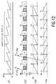
- FIG. 12summarizes the operation of the device of the invention.
- This figure 12shows the filling of the TRS memory by the CAN, which controls the compression of a frame by the DSP.
- This compressionends with an interrupt (see box K75, Figure 7), issued by the DSP and which allows the ⁇ P to read RMP ⁇ and send the compressed frame over the network via the AE2N access.
- the compression processhas priority over decompression and can even interrupt it.
- the decompression processis triggered (K14), at the same time as the IT K16, when the filling rate of the memory FP reaches the threshold TH1 (cf. FIG. 3).
- the line RM ⁇ in Figure 12shows the filling state of the RM ⁇ memory.
- FIG. 12illustrates an example for which the memory RM ⁇ receives too much data from the network in comparison with the data which it transmits to the DSP.
- OSE commandsare sent to the DSP and therefore certain frames received by the CNA are amputated by a sample. Thus the decompressions can be carried out at a faster frame rate. If the RM ⁇ memory does not receive enough data from the network, OIE commands will then be sent to the DSP.
Landscapes
- Engineering & Computer Science (AREA)
- Computer Networks & Wireless Communication (AREA)
- Signal Processing (AREA)
- Transmission Systems Not Characterized By The Medium Used For Transmission (AREA)
- Compression, Expansion, Code Conversion, And Decoders (AREA)
- Data Exchanges In Wide-Area Networks (AREA)
- Analogue/Digital Conversion (AREA)
Abstract
Description
Translated fromFrenchLa présente invention concerne un système de transmission de signaux vocaux sous forme de trames de signaux numériques, entre au moins un premier abonné et un deuxième abonné comportant notamment :
- ■ un milieu de transmission pour transmettre lesdites trames,
- ■ des premiers accès réception (AR1A, BR1A) pour recevoir des signaux analogiques vocaux desdits abonnés,
- ■ des premiers accès émission (AE1A, BE1A) pour fournir des signaux analogiques vocaux auxdits abonnés,
- ■ au moins un dispositif de codage-décodage (CVA) pour former lesdites trames de signaux numériques après compression des signaux analogiques vocaux et pour rétablir, sous forme analogique, les signaux vocaux analogiques après décompression des trames numériques, dispositif muni :
- d'un accès réception de trames pour recevoir lesdites trames (AR2N),
- d'un accès émission de trames pour fournir lesdites trames (AE2N),
- d'un circuit de compression-décompression (CPRSSA-DECPRSSA) pour effectuer lesdites opérations de compression et de décompression,
- de moyens de commandes couplés audit dispositif de compression-décompression pour commander la compression et la décompression.
- A transmission medium for transmitting said frames,
- ■ first reception accesses (AR1A, BR1A) for receiving analog voice signals from said subscribers,
- First transmission accesses (AE1A, BE1A) for supplying analog voice signals to said subscribers,
- ■ at least one coding-decoding device (CVA) for forming said digital signal frames after compression of the analog voice signals and for restoring, in analog form, the analog voice signals after decompression of the digital frames, device provided with:
- a frame reception access to receive said frames (AR2N),
- a transmission of frames access to supply said frames (AE2N),
- a compression-decompression circuit (CPRSSA-DECPRSSA) to perform said compression and decompression operations,
- control means coupled to said compression-decompression device for controlling compression and decompression.
L'invention concerne aussi un dispositif de codage-décodage pour un tel système.The invention also relates to a coding-decoding device for such a system.
L'application envisagée pour un tel système est de transmettre des communications téléphoniques sur un réseau numérique de données. Cette transmission de communications téléphoniques ne peut se faire, pour des raisons d'économie de débit à transmettre, que sous forme compressée.The application envisaged for such a system is to transmit telephone communications over a digital data network. This transmission of telephone communications can only be done, for reasons of economy of speed to be transmitted, in compressed form.
Les processus de compression et de décompression introduisent un retard auquel s'ajoute le délai de transmission sur le réseau numérique. Or, ce temps cumulé ne doit pas amener un retard qui excède 200 ms, sinon les abonnés ressentent une gêne importante dans leurs communications téléphoniques.The compression and decompression processes introduce a delay to which is added the transmission delay over the digital network. However, this cumulative time does not must not cause a delay that exceeds 200 ms, otherwise the subscribers experience significant discomfort in their telephone communications.
Ce problème du retard, aggravé par les processus de compression et de décompression, est mentionné dans l'article :
"CODING OF SPEECH AND WIDEBAND AUDIO." de Nikil S., et al., paru dans la revue éditée par AT&T TECHNICAL JOURNAL, datée d'octobre 1990. Les seuls moyens évoqués dans cet article pour minimiser ces retards sont d'utiliser un bon algorithme de compression-décompression.This delay problem, aggravated by the compression and decompression processes, is mentioned in the article:
"CODING OF SPEECH AND WIDEBAND AUDIO." by Nikil S., et al., published in the review published by AT&T TECHNICAL JOURNAL, dated October 1990. The only means mentioned in this article to minimize these delays are to use a good compression-decompression algorithm.
L'invention propose un système dans lequel des mesures ont été prises pour éviter un temps de retard trop important sans tenir compte de l'algorithme utilisé.The invention proposes a system in which measures have been taken to avoid too long a delay time without taking account of the algorithm used.
Pour cela, un tel système est remarquable en ce que :
- ■ le circuit de compression-décompression est conçu pour effectuer une compression et une décompression à la fois,
- ■ des moyens de priorité pour agir sur les moyens de commande pour mettre le dispositif de compression-décompression en position de compression prioritairement à la position de décompression.
- ■ the compression-decompression circuit is designed to perform compression and decompression at the same time,
- ■ priority means for acting on the control means to put the compression-decompression device in the compression position, primarily in the decompression position.
Ainsi, par l'invention, les processus de compression et de décompression sont en principe exécutés par des processeurs de signaux qui sont, en général, des dispositifs de traitement séquentiels, la proposition de priorité du dispositif de compression n'introduit donc pas de retard supplémentaire.Thus, by the invention, the compression and decompression processes are in principle executed by signal processors which are, in general, sequential processing devices, the priority proposition of the compression device therefore does not introduce any delay. additional.
On remarquera que, par l'invention, il est possible de n'utiliser qu'un seul de ces processeurs pour effectuer la compression et la décompression.It will be noted that, by the invention, it is possible to use only one of these processors for performing compression and decompression.
La description suivante faite en regard des dessins ci-annexés, le tout donné à titre d'exemple non limitatif, fera bien comprendre comment l'invention peut être réalisée.
- La figure 1 montre un système de l'invention.
- La figure 2 montre un dispositif de compression-décompression de l'invention.
- Les figures 3, 4, 5, 6 et 7 montrent des organigrammes explicitant le fonctionnement d'un premier processeur faisant partie du dispositif de la figure 2.
- Les figures 8, 9, 10 et 11 montrent des organigrammes explicitant le fonctionnement d'un second processeur faisant partie du dispositif de la figure 2.
- La figure 12 est un diagramme temps destiné à résumer le fonctionnement du dispositif de l'invention.
- Figure 1 shows a system of the invention.
- Figure 2 shows a compression-decompression device of the invention.
- Figures 3, 4, 5, 6 and 7 show flowcharts explaining the operation of a first processor forming part of the device of Figure 2.
- Figures 8, 9, 10 and 11 show flow charts explaining the operation of a second processor forming part of the device of Figure 2.
- FIG. 12 is a time diagram intended to summarize the operation of the device of the invention.
A la figure 1 la référence CA représente le combiné téléphonique d'un premier abonné rattaché à une extrémité A d'un système de transmission conforme à l'invention. Les signaux vocaux analogiques émanant du combiné CA sont reçus à un accès réception AR1A et les signaux vocaux que doit restituer le combiné CA sont fournis à un accès émission AE1A. La référence CB est la référence du combiné d'un deuxième abonné, rattaché à une extrémité B dudit système par l'intermédiaire d'accès BR1A et BE1A. Les signaux vocaux des deux abonnés rattachés aux extrémités A et B sont traités respectivement par des dispositifs de codage-décodage CVA et CVB. Ces dispositifs CVA et CVB comprennent respectivement des circuits de compression-décompression formés d'une unité de compression CPRSSA et d'une unité de décompression DECPRSSA pour le dispositif CVA et d'une unité de compression CPRSSB et d'une unité de décompression DECPRSSB pour le dispositif CVB. Les signaux vocaux numériques, comprimés par le dispositif CPRSSA, sont rendus disponibles à un accès AE2N du dispositif CVA et les signaux vocaux numériques, comprimés par le dispositif CPRSSB, sont rendus disponibles à un accès BE2N du dispositif CVB. Ces signaux vocaux comprimés par les dispositifs CPRSSA et CPRSSB sont respectivement transmis via le réseau aux accès BR2N et AR2N pour y être décompressés. Les signaux vocaux de l'accès AE2N sont appliqués à une entrée d'un multiplexeur MUXA qui peut être relié par ses autres entrées à d'autres sources de données de natures différentes de celles des signaux vocaux. Un multiplexeur MUXB est prévu au niveau de l'extrémité B pour les mêmes fonctions que le multiplexeur MUXA. De manière similaire, les données appliquées à l'accès AR2N proviennent de la sortie d'un démultiplexeur DEMUXA et celles appliquées à l'accès BR2N de la sortie d'un démultiplexeur DEMUXB. Le multiplexeur MUXA et le démultiplexeur DEMUXB sont reliés par une liaison LAB, tandis que le multiplexeur MUXB et le démultiplexeur DEMUXA sont reliés par une liaison LBA. Ces liaisons peuvent être réalisées de différentes manières, par exemple au moyen d'un réseau de type LAN (réseau local) ou WAN (réseau à longue distance).In Figure 1 the reference CA represents the telephone handset of a first subscriber attached to one end A of a transmission system according to the invention. Analog voice signals from the CA handset are received at an AR1A receive port and voice signals to be output from the CA handset are supplied to an AE1A transmit port. The reference CB is the reference of the handset of a second subscriber, attached to one end B of said system via access BR1A and BE1A. The voice signals of the two subscribers attached to the ends A and B are processed respectively by coding-decoding devices CVA and CVB. These CVA and CVB devices respectively comprise compression-decompression circuits formed by a CPRSSA compression unit and a DECPRSSA decompression unit for the CVA device and by a CPRSSB compression unit and a DECPRSSB decompression unit for the CVB system. The digital voice signals, compressed by the CPRSSA device, are made available to an AE2N access of the CVA device and the digital voice signals, compressed by the CPRSSB device, are made available to a BE2N access of the CVB device. These voice signals compressed by the CPRSSA and CPRSSB devices are respectively transmitted via the network to the BR2N and AR2N ports to be decompressed there. The voice signals of the AE2N access are applied to an input of a MUXA multiplexer which can be connected by its other inputs to other sources of data of natures different from those of the voice signals. An MUXB multiplexer is planned at end B for the same functions as the MUXA multiplexer. Similarly, the data applied to the AR2N access comes from the output of a DEMUXA demultiplexer and that applied to the BR2N access from the output of a DEMUXB demultiplexer. The MUXA multiplexer and the DEMUXB demultiplexer are connected by an LAB link, while the MUXB multiplexer and the DEMUXA demultiplexer are connected by an LBA link. These connections can be made in different ways, for example by means of a LAN (local area network) or WAN (long distance network) type network.
A la figure 2, on a détaillé la structure du dispositif de compression-décompression CVA. Il va de soi que le dispositif CVB peut avoir d'une manière avantageuse une structure identique.In FIG. 2, the structure of the compression-decompression device CVA has been detailed. It goes without saying that the CVB device can advantageously have an identical structure.
Ce dispositif est formé d'un convertisseur CNA_AN qui effectue les opérations de conversion analogique-numérique d'une part, et les opérations de conversion numérique-analogique d'autre part. Ce convertisseur est relié par les accès AR1A et AE1A pour signaux analogiques au combiné CA. Un processeur de signal DSP traite les données provenant du convertisseur CNA_AN et lui fournit des données numériques. Ce processeur DSP est affecté principalement aux tâches de compression et de décompression selon un algorithme qui peut être celui décrit dans l'article précité. Ce processeur DSP est muni d'une entrée HLD pour recevoir des signaux d'accusé réception, de sorties XF et

- une information OIE signalant une demande d'insertion d'un échantillon factice pour le convertisseur CNA_AN,
- une information OSE signalant une demande de suppression d'un échantillon pour le convertisseur CNA_AN,
- une information EOA signalant que les insertions ou les suppressions d'échantillons doivent s'effectuer sur des périodes de silence ou non.
- OIE information signaling a request to insert a dummy sample for the CNA_AN converter,
- OSE information signaling a request to delete a sample for the CNA_AN converter,
- EOA information indicating that the insertions or deletions of samples must be carried out during periods of silence or not.
Le fonctionnement d'un tel dispositif de codage-décodage est expliqué par les organigrammes suivants.The operation of such a coding-decoding device is explained by the following flowcharts.
L'organigramme de la figure 3 représente un programme d'interruption qui est déclenché par une interruption surgissant à un cadence fixe. L'apparition de cette interruption survenant, dans le cadre de l'exemple décrit, toutes les 125 µs, est fixée par le rythme de travail du convertisseur CNA_AN. Ceci est noté à la case KO. Une première tâche effectuée par ce programme d'interruption consiste à lire un échantillon Ec formé par le convertisseur CNA_AN (case K2) et à le mettre dans la mémoire TRS. Une deuxième tâche indiquée à la case K4 consiste à fournir au convertisseur CNA_AN un échantillon provenant de la mémoire FP en un emplacement défini par le pointeur PtrC qui est ensuite incrémenté d'une unité. La case K5 montre un test pour savoir si la mémoire TRS est pleine ou non. Si elle est pleine, on va à la case K6 où une variable COMP est mise à "1". Ceci aura pour conséquence, comme on le verra dans la suite du présent exposé, de déclencher l'algorithme de compression par le processeur DSP. Puis, comme indiqué à la case K7, la mémoire TRS est réinitialisée, son pointeur est remis à sa position initiale pour qu'à la prochaine opération la concernant, le premier emplacement soit utilisé. A la case K8 qui suit la case K7, on examine l'état de remplissage ER de la mémoire en pile FP. Ceci est simplement calculé en effectuant la différence desdits pointeurs PtrC et PtrF. Cet état est testé à la case K10. Pour que cet état soit déclaré satisfaisant, il faut que cette différence soit égale à une valeur TH1. Cette valeur correspond au temps maximum nécessaire au processeur DSP pour décompresser une trame, sachant que le processus de compression est prioritaire.The flowchart in Figure 3 shows an interrupt program which is triggered by an interrupt occurring at a fixed rate. The appearance of this interruption occurring, in the context of the example described, every 125 μs, is fixed by the working rhythm of the CNA_AN converter. This is noted in the KO box. A first task performed by this interruption program consists in reading a sample Ec formed by the converter CNA_AN (box K2) and putting it in the memory TRS. A second task indicated in box K4 consists in providing the converter CNA_AN with a sample coming from the memory FP at a location defined by the pointer PtrC which is then incremented by one. Box K5 shows a test to know whether the TRS memory is full or not. If it is full, we go to box K6 where a COMP variable is set to "1". This will have the consequence, as will be seen in the remainder of this presentation, of triggering the compression algorithm by the DSP processor. Then, as indicated in box K7, the memory TRS is reset, its pointer is returned to its initial position so that the next operation concerning it, the first location is used. In box K8 which follows box K7, the state of filling ER of the memory in stack FP is examined. This is simply calculated by performing the difference of said pointers PtrC and PtrF. This state is tested in box K10. For this state to be declared satisfactory, this difference must be equal to a value TH1. This value corresponds to the maximum time necessary for the DSP processor to decompress a frame, knowing that the compression process has priority.
Si on estime que l'état testé à la case K10 est satisfaisant, on met à "1" une variable DECOMP qui va autoriser le processus de décompression (case K14). On déclenche ensuite, comme indiqué à la case K16, une interruption sur la borne IPL1 vers le processeur pour que d'autres informations compressées soient fournies au processeur DSP, comme cela va être décrit par la suite.If it is considered that the state tested in box K10 is satisfactory, a variable DECOMP is set to "1" which will authorize the decompression process (box K14). Then, as indicated in box K16, an interruption is triggered on the terminal IPL1 to the processor so that other compressed information is supplied to the processor DSP, as will be described below.
Si cet état n'est pas satisfaisant, on teste tout d'abord, à la case K18, les valeurs relatives des pointeurs PtrC et PtrF. Si la valeur de PtrC est inférieure à celle de PtrF, aucune mesure n'est entreprise et le programme d'interruption est terminé. Si la valeur de PtrC est supérieure à celle de PtrF, on procède alors, case K19, aux réinitialisations des différents pointeurs PtrC, PtrF et de la mémoire FP. Notamment, le pointeur PtrF est affecté de la valeur Init_PtrF.If this state is not satisfactory, first of all, in box K18, the relative values of the pointers PtrC and PtrF are tested. If the value of PtrC is less than that of PtrF, no action is taken and the interrupt program is terminated. If the value of PtrC is greater than that of PtrF, box K19 is then carried out to reinitialize the various pointers PtrC, PtrF and the memory FP. In particular, the PtrF pointer is assigned the value Init_PtrF.
La figure 4 est l'organigramme montrant le fonctionnement global du processeur DSP, c'est un programme bouclé sur lui-même. Il se compose essentiellement de deux tests indiqués respectivement aux cases K20 et K22. Le premier teste la valeur de la variable COMP déjà mentionnée et le deuxième la valeur de la variable DECOMP. Si COMP a la valeur "1", on effectue le sous-programme SBCPRS relatif à la compression (case K27). Si DECOMP a la valeur "1", on effectue le sous-programme SBDCPRS relatif à la décompression (case K28). Il va de soi qu'un tel programme subit les interruptions du convertisseur CNA_AN et que, notamment les valeurs COMP et DECOMP peuvent changer. Ainsi, dans le sous-programme SBDCPRS, montré à la figure 5, on examine périodiquement si la valeur COMP a la valeur "1" (voir cases K401, K402, ...., K40n). Si la valeur "1" est présente, le sous-programme SBDCPRS est en quelque sorte interrompu, conformément à l'invention, afin que le sous-programme SBCPRS soit exécuté en priorité. Les lignes en pointillé "lpp" représentées à cette figure 5 sont des lignes de programme relatives à la décompression qui ne sont pas explicitées car ne rentrant pas dans le cadre de l'invention. Mais ces lignes peuvent être établies à partir de la lecture de l'article précité.Figure 4 is the flowchart showing the overall operation of the DSP processor, it is a program looped on itself. It essentially consists of two tests indicated respectively in boxes K20 and K22. The first tests the value of the COMP variable already mentioned and the second tests the value of the DECOMP variable. If COMP has the value "1", the SBCPRS subroutine relating to compression is carried out (box K27). If DECOMP has the value "1", the SBDCPRS subroutine relating to decompression is carried out (box K28). It goes without saying that such a program undergoes the interruptions of the converter CNA_AN and that, in particular the values COMP and DECOMP can change. Thus, in the sub-program SBDCPRS, shown in FIG. 5, it is periodically examined whether the value COMP has the value "1" (see boxes K401 , K402 , ...., K40n ). If the value "1" is present, the sub-program SBDCPRS is in somehow interrupted, in accordance with the invention, so that the SBCPRS routine is executed in priority. The dotted lines "lpp" represented in this FIG. 5 are program lines relating to decompression which are not explained because they do not come within the scope of the invention. But these lines can be established from reading the aforementioned article.
Le sous-programme SBDCPRS se termine par un appel à un sous-programme SBINSUP, montré à la figure 6.The SBDCPRS subroutine ends with a call to an SBINSUP subroutine, shown in Figure 6.
Ce sous-programme commence par l'analyse de l'en-tête de la trame de signaux vocaux numériques compressés contenue dans la mémoire RMPµ. Les cases K52, K53 et K54 qui suivent indiquent des tests pour savoir si les informations précitées OSE, OIE et EOA sont égales à "1". Si OSE a la valeur "1", un compteur cpt est décrémenté d'une unité (case K56). Il va de soi qu'un tel compteur a été initialisé à zéro, au préalable d'une communication. Si OIE a la valeur "1", ce compteur cpt est incrémenté d'une unité (case K57). Si l'ordre EOA a la valeur "1", on teste tout de suite, à la case K60, le contenu du compteur cpt. Si celui-ci est positif on insère un échantillon. Pour cela, différentes actions sont entreprises : on incrémente la valeur d'initialisation du pointeur PtrF (case K62) de manière à augmenter la taille de la trame nouvellement décompressée (figure 5) et donc la mémoire tampon FP, en la faisant passer de N à N + 1 échantillons, ce qui a pour effet de ralentir les échanges de trames entre le DSP et le µP (cases K8, K10, K14 et K16) et on décrémente d'une unité le compteur cpt. Si le test indiqué à la case K60 est négatif, on teste, alors, si le contenu du compteur cpt est négatif (case K65). Si celui-ci est négatif on va supprimer le dernier échantillon (case K68). Pour cela, on décrémente la valeur initiale # finFP du pointeur PtrF : Init_PtrF, d'une unité pour diminuer la taille de la trame nouvellement décompressée, et par conséquent la taille de la mémoire tampon FP en la faisant passer de N à N - 1 échantillons, ce qui a pour effet d'accélérer les échanges de trames entre le DSP et le µP (cases K8, K10, K14 et K16) et on incrémente d'une unité le compteur cpt. Ensuite, on incrémente le pointeur PtrC d'une unité de sorte qu'un échantillon sera sauté lors de sa lecture indiquée à la case K4 de la figure 3. Si le test de la case K65 est négatif, cela signifie que la valeur de "cpt" est "0", on passe alors à la case K70, où la valeur initiale de PtrF correspond à sa valeur nominale. Si le code EOA n'a pas été envoyé, on passe à la case K55 pour savoir si on est en présence d'échantillons de silence. S'il n'y a pas de silence, aucune action n'est entreprise. Si l'on détecte du silence, on passe à la case K60.This subroutine begins with the analysis of the header of the frame of compressed digital voice signals contained in the memory RMPµ. The boxes K52, K53 and K54 which follow indicate tests to determine whether the above-mentioned information OSE, OIE and EOA are equal to "1". If OSE has the value "1", a cpt counter is decremented by one unit (box K56). It goes without saying that such a counter has been initialized to zero, prior to communication. If OIE has the value "1", this counter cpt is incremented by one (box K57). If the EOA command has the value "1", we immediately test, in box K60, the content of the counter cpt. If this is positive, a sample is inserted. To do this, various actions are taken: the initialization value of the PtrF pointer is incremented (box K62) so as to increase the size of the newly decompressed frame (FIG. 5) and therefore the buffer FP, by passing it from N at N + 1 samples, which has the effect of slowing the exchange of frames between the DSP and the µP (boxes K8, K10, K14 and K16) and the cpt counter is decremented by one. If the test indicated in box K60 is negative, we then test whether the content of the cpt counter is negative (box K65). If this is negative, the last sample will be deleted (box K68). For this, the initial value # finFP of the PtrF pointer: Init_PtrF is decremented by one to decrease the size of the newly decompressed frame, and consequently the size of the FP buffer by passing it from N to N - 1 samples, which has the effect of speeding up the exchange of frames between the DSP and the µP (boxes K8, K10, K14 and K16) and the unit is incremented by one counter cpt. Then, the PtrC pointer is incremented by one so that a sample will be skipped when it is read, indicated in box K4 in Figure 3. If the test in box K65 is negative, this means that the value of " cpt "is" 0 ", then we go to box K70, where the initial value of PtrF corresponds to its nominal value. If the EOA code has not been sent, we go to box K55 to find out if we are in the presence of samples of silence. If there is no silence, no action is taken. If we detect silence, we go to box K60.
La figure 7 explicite le sous-programme de compression SBCPRS. La première tâche effectuée dans ce sous-programme est montrée à la case K72. Elle consiste à mettre à zéro la variable COMP. Puis on teste l'énergie moyenne EN des échantillons à comprimer. Si cette valeur est inférieure à une certaine valeur TH2, on considère que ces échantillons représentent du silence et on passe à la case K74 où l'on met à "1" la variable SIL pour indiquer ce fait et le sous-programme est terminé en passant par la case K75, qui implique le déclenchement d'une interruption pour le processeur µP, déclenchée par un signal appliqué à l'entrée IPL2. Si l'on n'a pas affaire à des échantillons de silence, alors la variable SIL est mise à zéro, case K76, et l'on passe à la case K77 qui indique le déclenchement du sous-programme de compression ACMPRS avant de passer à la case K75. Ce sous-programme de compression peut être établi au moyen de l'enseignement fourni par l'article précité.Figure 7 shows the SBCPRS compression routine. The first task performed in this subroutine is shown in box K72. It consists in setting the COMP variable to zero. Then the average energy EN of the samples to be compressed is tested. If this value is less than a certain TH2 value, we consider that these samples represent silence and we go to box K74 where we put the variable SIL to "1" to indicate this fact and the subroutine is ended passing through box K75, which implies the triggering of an interrupt for the µP processor, triggered by a signal applied to the IPL2 input. If we are not dealing with samples of silence, then the SIL variable is set to zero, box K76, and we move to box K77 which indicates the triggering of the ACMPRS compression subroutine before proceeding in box K75. This compression subroutine can be established by means of the teaching provided by the above-mentioned article.
La figure 8 montre un premier organigramme explicitant le fonctionnement du processeur µP. Cet organigramme est relatif à un programme d'interruption déclenché au niveau du port série du processeur. Ce processeur est, en effet, muni d'un système pour gérer une liaison série qui est connectée à l'accès AR2N. C'est l'accès qui reçoit les trames de signaux numériques compressés. Dès que la mémoire tampon BUFµ associée à ce port série est pleine, elle contient alors une trame constituée d'un paquet de parole compressée, d'octets d'adressage et de contrôle. Une interruption est déclenchée à l'intérieur du processeur µP (case K80). Cette interruption entraîne une première action qui consiste à libérer cette mémoire BUFµ en transférant son contenu dans la mémoire RMµ (case K82). Une deuxième action est indiquée à la case K84, on attribue une date "tA" à la trame ainsi transférée. Cette date est insérée dans l'en-tête de trame HE.Figure 8 shows a first flowchart explaining the operation of the µP processor. This flowchart relates to an interrupt program triggered at the serial port of the processor. This processor is, in fact, provided with a system for managing a serial link which is connected to the AR2N access. It is the access which receives the compressed digital signal frames. As soon as the BUFµ buffer associated with this serial port is full, it then contains a frame consisting of a packet of compressed speech, addressing and control bytes. An interrupt is triggered inside the µP processor (box K80). This interruption leads to a first action which consists in freeing this memory BUFµ by transferring its content to the memory RMµ (box K82). A second action is indicated in box K84, a date "tA" is assigned to the frame thus transferred. This date is inserted in the HE frame header.
La figure 9 montre un deuxième organigramme explicitant le fonctionnement du processeur µP. Cet organigramme est relatif à un premier programme d'interruption réception déclenché par le processeur DSP au moyen d'un signal appliqué à l'entrée IPL1 (case K16 de la figure 3). On prélève, comme indiqué à la case K94, l'en-tête HE, de la trame la plus ancienne et celle-ci est transférée dans la mémoire RHPµ (case K95). Puis on détermine une date "tD" liée à ce dernier événement (case K96). La case K98, qui suit, explicite une durée "t1" qui est la différence entre les dates "tA" et "tD".
A la case K100, on indique une comparaison de cette valeur t1 à une grandeur mint1 qui a été initialisée à une valeur importante, lors de l'établissement de la communication notamment. Si t1 est plus petit que mint1, alors mint1 prend la valeur de t1 (case K102). Puis, on passe à la case K104 où l'on teste la valeur de t1 par rapport à une valeur maxt1 qui a été initialisée à une petite valeur lors de l'initialisation. Si t1 est plus grand que la valeur maxt1, alors maxt1 prend la valeur t1 (case K106). La case K108 qui termine ce programme d'interruption incrémente une variable de chronométrage TMR d'une unité.Figure 9 shows a second flowchart explaining the operation of the µP processor. This flowchart relates to a first reception interruption program triggered by the DSP processor by means of a signal applied to the input IPL1 (box K16 in FIG. 3). As shown in box K94, the HE header is taken from the oldest frame and this is transferred to the memory RHPµ (box K95). Then a date "tD" linked to this last event is determined (box K96). Box K98, which follows, explains a duration "t1" which is the difference between the dates "tA" and "tD".
In box K100, a comparison of this value t1 is indicated with a quantity mint1 which has been initialized to a large value, notably during the establishment of the communication. If t1 is smaller than mint1, then mint1 takes the value of t1 (box K102). Then, we pass to box K104 where we test the value of t1 with respect to a value maxt1 which was initialized to a small value during initialization. If t1 is greater than the value maxt1, then maxt1 takes the value t1 (box K106). Box K108 which ends this interrupt program increments a TMR timing variable by one unit.
La figure 10 montre un troisième organigramme explicitant le fonctionnement du processeur µP. Cet organigramme est relatif à un programme d'interruption déclenché sur la ligne IPL2 par le DSP à la fin du processus de compression. Cette interruption, indiquée à la case K300, provoque l'émission sur la ligne LAB en passant par l'accès AE2N d'une trame de signaux compressés qui était contenue dans une partie TR de la mémoire RHPµ (case K302).Figure 10 shows a third flowchart explaining the operation of the µP processor. This flowchart relates to an interrupt program triggered on the IPL2 line by the DSP at the end of the compression process. This interruption, indicated in box K300, causes the transmission on the line LAB via the access AE2N of a frame of compressed signals which was contained in a part TR of the memory RHPµ (box K302).
La figure 11 est l'organigramme montrant le fonctionnement global du processeur µP, c'est un programme bouclé sur lui-même.Figure 11 is the flowchart showing the overall operation of the µP processor, it is a program looped on itself.
Ce programe débute à la case K200 où l'on teste la valeur du compteur TMR par rapport à une valeur trames M transmise pendant un temps de l'ordre de 10 s par exemple (1/20 ms * 10 s = 500 trames).
M représente le nombre de trames à attendre pour gérer l'offset de fréquence (Δ) entre les cartes CVA et CVB. La valeur de M est encadrée par le maximum de l'offset et par le taux de pleurage maximum toléré (T). Plus précisément, on choisit M tel que : Δ<(M*N)-1<τ, avec N, le nombre d'échantillons par trame. Si cette valeur n'est pas atteinte, aucune action n'est entreprise et l'on va à la case K210 qui représente différentes tâches que le processeur a à effectuer et qui n'ont pas à être détaillées car ne faisant pas partie de l'invention. Si la période est écoulée, on va à la case K220 qui indique l'initialisation à zéro de différentes valeurs OIE, OSE, EOA et TMR. On passe ensuite à la case K222 où l'on teste la valeur mint1 à une valeur t2 qui est une marge de sécurité minimum pour que la pile de réception des trames du réseau, RMµ, ne soit jamais vide lors d'une requête DSP pour une décompression. Cette marge a été choisie proche de 5 ms. Si la valeur mint1 est inférieure à cette valeur t2, cela veut dire que la pile RMµ se vide et qu'il convient de rajouter des échantillons. Pour cela, la valeur OIE = 1 est mise dans l'en-tête de la trame, c'est ce qui est indiqué à la case K224. Si la valeur mintl excède la valeur t2, alors il convient d'entreprendre la mesure inverse, c'est-à-dire de supprimer des échantillons. La case K226 montre la mise dans l'en-tête de la valeur "1" à la variable OSE. La case K228 qui suit est une mesure et un test de l'écart de gigue. Ceci est obtenu en effectuant la différence entre maxt1 et mint1. Si cet écart est trop grand et supérieur à une valeur t3, qui est de l'ordre de M divisé par la fréquence d'échantillonnage soit environ 5 ms, alors on prend des mesures plus draconiennes. Ces mesures consistent à mettre à "1" la variable EOA dans l'en-tête (case K230) afin que le processeur DSP insère un échantillon dans toutes les trames même si elles ne concernent pas du silence. Après ces mesures, on passe à la case K235 qui indique une réinitialisation des valeurs mint1 et maxt1.This program starts in box K200 where the value of the TMR counter is tested with respect to a frame value M transmitted for a time of the order of 10 s for example (1/20 ms * 10 s = 500 frames).
M represents the number of frames to wait to manage the frequency offset (Δ) between the CVA and CVB cards. The value of M is framed by the maximum offset and by the maximum tolerated cry rate (T). More precisely, we choose M such that: Δ <(M * N)-1 <τ, with N, the number of samples per frame. If this value is not reached, no action is taken and we go to box K210 which represents different tasks that the processor has to perform and which do not have to be detailed because they are not part of the 'invention. If the period has elapsed, we go to box K220 which indicates the initialization to zero of different OIE, OSE, EOA and TMR values. We then go to box K222 where we test the value mint1 at a value t2 which is a minimum safety margin so that the stack for receiving network frames, RMµ, is never empty during a DSP request for decompression. This margin was chosen close to 5 ms. If the value mint1 is less than this value t2, this means that the RMµ stack is empty and that samples must be added. For this, the value OIE = 1 is put in the header of the frame, this is what is indicated in box K224. If the value mintl exceeds the value t2, then it is advisable to undertake the reverse measurement, that is to say to delete samples. Box K226 shows the setting in the header of the value "1" to the variable OSE. Box K228 which follows is a measurement and a test of the jitter deviation. This is obtained by making the difference between maxt1 and mint1. If this difference is too large and greater than a value t3, which is of the order of M divided by the sampling frequency, ie approximately 5 ms, then more drastic measures are taken. These measures consist in setting the variable EOA to "1" in the header (box K230) so that the DSP processor inserts a sample in all the frames even if they do not concern silence. After these measurements, we go to box K235 which indicates a reset of the values mint1 and maxt1.
La figure 12 résume le fonctionnement du dispositif de l'invention. Cette figure 12 montre le remplissage de la mémoire TRS par le CAN, qui commande la compression d'une trame par le DSP. Cette compression se termine par une interruption (cf case K75, figure 7), émise par le DSP et qui permet au µP de lire RMPµ et d'envoyer la trame compressée sur le réseau via l'accès AE2N. On remarque que le processus de compression est prioritaire par rapport à la décompression et peut même l'interrompre. Le processus de décompression est déclenché (K14), en même temps que l'IT K16, lorsque le taux de remplissage de la mémoire FP atteint le seuil TH1 (cf figure 3). La ligne RMµ de la figure 12 montre l'état de remplissage de la mémoire RMµ. Sur l'interruption K16, le µP exécute le sous-programme de la figure 9, et écrit donc une trame compressée dans la mémoire RMPµ accompagnée notamment d'une commande OIE/OSE. La figure 12 illustre un exemple pour lequel la mémoire RMµ reçoit trop de données du réseau en comparaison des données qu'elle émet vers le DSP. Ainsi des commandes OSE sont envoyées vers le DSP et donc certaines trames reçues par le CNA sont amputées d'un échantillon. Ainsi les décompressions peuvent être effectuées à un rythme trame plus rapide. Dans un cas contraire où la mémoire RMµ ne recevrait pas assez de données du réseau, des commandes OIE seraient alors envoyées vers le DSP.Figure 12 summarizes the operation of the device of the invention. This figure 12 shows the filling of the TRS memory by the CAN, which controls the compression of a frame by the DSP. This compression ends with an interrupt (see box K75, Figure 7), issued by the DSP and which allows the µP to read RMPµ and send the compressed frame over the network via the AE2N access. We note that the compression process has priority over decompression and can even interrupt it. The decompression process is triggered (K14), at the same time as the IT K16, when the filling rate of the memory FP reaches the threshold TH1 (cf. FIG. 3). The line RMµ in Figure 12 shows the filling state of the RMµ memory. On the interrupt K16, the µP executes the subroutine of FIG. 9, and therefore writes a compressed frame in the memory RMPµ accompanied in particular by an OIE / OSE command. FIG. 12 illustrates an example for which the memory RM μ receives too much data from the network in comparison with the data which it transmits to the DSP. Thus OSE commands are sent to the DSP and therefore certain frames received by the CNA are amputated by a sample. Thus the decompressions can be carried out at a faster frame rate. If the RMµ memory does not receive enough data from the network, OIE commands will then be sent to the DSP.
Claims (6)
Translated fromFrenchet en ce qu'il est prévu :
and that it is planned:
des deuxièmes moyens de gestion pour fournir une trame reçue à l'accès réception (AR2N) audit circuit de compression-décompression pour minimiser le temps de traversée.Transmission system according to claim 2, characterized in that the coding-decoding device (CVA) comprises:
second management means for supplying a frame received at the reception access (AR2N) to said compression-decompression circuit in order to minimize the crossing time.
des moyens pour compenser la gigue apportée par le milieu de transmission.Transmission system according to one of claims 1 to 4, characterized in that the coding-decoding device (CVA) comprises:
means to compensate for the jitter provided by the transmission medium.
Applications Claiming Priority (2)
| Application Number | Priority Date | Filing Date | Title |
|---|---|---|---|
| FR9415408AFR2728750A1 (en) | 1994-12-21 | 1994-12-21 | SYSTEM FOR TRANSMITTING VOICE SIGNALS IN DIGITAL FORM AND DEVICE FOR CODING-DECODING FOR SUCH A SYSTEM |
| FR9415408 | 1994-12-21 |
Publications (1)
| Publication Number | Publication Date |
|---|---|
| EP0723346A1true EP0723346A1 (en) | 1996-07-24 |
Family
ID=9470058
Family Applications (1)
| Application Number | Title | Priority Date | Filing Date |
|---|---|---|---|
| EP95203454AWithdrawnEP0723346A1 (en) | 1994-12-21 | 1995-12-12 | Transmission system for digital speech signals and device for coding/decoding to be used in the system |
Country Status (4)
| Country | Link |
|---|---|
| US (1) | US5787119A (en) |
| EP (1) | EP0723346A1 (en) |
| JP (1) | JPH08274725A (en) |
| FR (1) | FR2728750A1 (en) |
Families Citing this family (1)
| Publication number | Priority date | Publication date | Assignee | Title |
|---|---|---|---|---|
| US5953509A (en)* | 1997-05-08 | 1999-09-14 | Periphonics Corporation | Multiprocessor interface adaptor with broadcast function |
Citations (2)
| Publication number | Priority date | Publication date | Assignee | Title |
|---|---|---|---|---|
| US4823342A (en)* | 1986-02-07 | 1989-04-18 | Hitachi, Ltd. | Time division exchange system having functions of compressing and expanding information |
| US4839906A (en)* | 1988-05-20 | 1989-06-13 | Amaf Industries, Inc. | Processor based linked compressor-expander telecommunications system |
Family Cites Families (1)
| Publication number | Priority date | Publication date | Assignee | Title |
|---|---|---|---|---|
| US5455576A (en)* | 1992-12-23 | 1995-10-03 | Hewlett Packard Corporation | Apparatus and methods for Lempel Ziv data compression with improved management of multiple dictionaries in content addressable memory |
- 1994
- 1994-12-21FRFR9415408Apatent/FR2728750A1/enactivePending
- 1995
- 1995-12-12EPEP95203454Apatent/EP0723346A1/ennot_activeWithdrawn
- 1995-12-18USUS08/573,851patent/US5787119A/ennot_activeExpired - Fee Related
- 1995-12-18JPJP7329331Apatent/JPH08274725A/enactivePending
Patent Citations (2)
| Publication number | Priority date | Publication date | Assignee | Title |
|---|---|---|---|---|
| US4823342A (en)* | 1986-02-07 | 1989-04-18 | Hitachi, Ltd. | Time division exchange system having functions of compressing and expanding information |
| US4839906A (en)* | 1988-05-20 | 1989-06-13 | Amaf Industries, Inc. | Processor based linked compressor-expander telecommunications system |
Non-Patent Citations (1)
| Title |
|---|
| "Audio decompression IC is first single chip decoding system", COMPUTER DESIGN, vol. 32, no. 10, WESTFORD, MASSACHUSETTS US, pages 110* |
Also Published As
| Publication number | Publication date |
|---|---|
| US5787119A (en) | 1998-07-28 |
| FR2728750A1 (en) | 1996-06-28 |
| JPH08274725A (en) | 1996-10-18 |
Similar Documents
| Publication | Publication Date | Title |
|---|---|---|
| EP0139803B1 (en) | Method of recovering lost information in a digital speech transmission system, and transmission system using said method | |
| EP0162174B1 (en) | Buffer device used in a voice transmission network | |
| EP0041429B1 (en) | Process and device for the synchronization of digital signals | |
| KR950002751B1 (en) | Packet generating device | |
| FR2680256A1 (en) | DATA TRANSFER APPARATUS AND METHOD FOR COMMUNICATING BETWEEN A DEVICE AND A BUS CONTROL DEVICE. | |
| FR2681743A1 (en) | APPARATUS AND METHOD FOR TRANSFERRING PRIORITY AFFECTED DATA FOR RADIOTELEPHONE DEVICE. | |
| FR2749462A1 (en) | AUTONOMOUS DEVICE, PARTICULARLY ACTIVE IMPLANTABLE MEDICAL DEVICE AND ITS SYNCHRONOUS TRANSMISSION EXTERNAL PROGRAMMER | |
| CA2006831C (en) | System with a single hdlc circuit and a conversion buffer memory for transmitting hdlc frames over a pcm channel | |
| FR2476413A1 (en) | TRANSPARENT NETWORK FOR THE SATELLITE TRANSMISSION OF DATA SIGNALS AND CONVERSION SIGNALS | |
| CN105632541B (en) | A kind of method, system and the mobile phone of recording mobile phone output audio | |
| EP1545032A2 (en) | Method and device for synchronisation of clocks of digital encoders and decoders | |
| EP1306689A1 (en) | Method and system for recording and synchronized reading of data coming from a plurality of terminals | |
| EP0404000A1 (en) | Vocal message equipment for switching exchange | |
| CA2001068C (en) | Method for transmitting data on the internal bus of a workstation, internal bus device implementing said method and matching circuit for said internal bus | |
| EP0723346A1 (en) | Transmission system for digital speech signals and device for coding/decoding to be used in the system | |
| FR2571917A1 (en) | INTERFACE CIRCUIT FOR CONNECTING A DIGITAL EQUIPMENT TO A TIME MULTIPLEX LINK | |
| FR2523387A1 (en) | TELEPHONE CONFERENCE CIRCUIT | |
| EP2203915A1 (en) | Transmission error dissimulation in a digital signal with complexity distribution | |
| EP0555138A1 (en) | Method, system and processor for communications between a plurality of equipment subsystems | |
| EP0063990A1 (en) | Method for image transmission with reduced data rate; transmission system for executing this method | |
| EP1245099B1 (en) | Packet reception device | |
| EP0011540B1 (en) | Input-output interface device between a data switcher and a plurality of transmission lines | |
| CA2067902C (en) | Method and device for detecting and controlling the format of digital messages transmitted to a receiving device | |
| LU82894A1 (en) | DEVICE FOR MEASURING THE ATTENUATION OF A TRANSMISSION PATH | |
| EP0397559A1 (en) | Digital data generator |
Legal Events
| Date | Code | Title | Description |
|---|---|---|---|
| PUAI | Public reference made under article 153(3) epc to a published international application that has entered the european phase | Free format text:ORIGINAL CODE: 0009012 | |
| AK | Designated contracting states | Kind code of ref document:A1 Designated state(s):DE FR GB | |
| 17P | Request for examination filed | Effective date:19970124 | |
| RAP1 | Party data changed (applicant data changed or rights of an application transferred) | Owner name:PHILIPS ELECTRONICS N.V. Owner name:PHILIPS COMMUNICATION D'ENTREPRISE | |
| RAP1 | Party data changed (applicant data changed or rights of an application transferred) | Owner name:COMPAGNIE DES SIGNAUX Owner name:PCE | |
| STAA | Information on the status of an ep patent application or granted ep patent | Free format text:STATUS: THE APPLICATION HAS BEEN WITHDRAWN | |
| 18W | Application withdrawn | Withdrawal date:19991206 |