EP0721615B1 - Force reflecting haptic interface - Google Patents
Force reflecting haptic interfaceDownload PDFInfo
- Publication number
- EP0721615B1 EP0721615B1EP94930465AEP94930465AEP0721615B1EP 0721615 B1EP0721615 B1EP 0721615B1EP 94930465 AEP94930465 AEP 94930465AEP 94930465 AEP94930465 AEP 94930465AEP 0721615 B1EP0721615 B1EP 0721615B1
- Authority
- EP
- European Patent Office
- Prior art keywords
- user
- connection element
- freedoms
- force
- relative
- Prior art date
- Legal status (The legal status is an assumption and is not a legal conclusion. Google has not performed a legal analysis and makes no representation as to the accuracy of the status listed.)
- Expired - Lifetime
Links
Images


Classifications
- G—PHYSICS
- G05—CONTROLLING; REGULATING
- G05B—CONTROL OR REGULATING SYSTEMS IN GENERAL; FUNCTIONAL ELEMENTS OF SUCH SYSTEMS; MONITORING OR TESTING ARRANGEMENTS FOR SUCH SYSTEMS OR ELEMENTS
- G05B11/00—Automatic controllers
- G05B11/01—Automatic controllers electric
- B—PERFORMING OPERATIONS; TRANSPORTING
- B25—HAND TOOLS; PORTABLE POWER-DRIVEN TOOLS; MANIPULATORS
- B25J—MANIPULATORS; CHAMBERS PROVIDED WITH MANIPULATION DEVICES
- B25J9/00—Programme-controlled manipulators
- B25J9/16—Programme controls
- B25J9/1679—Programme controls characterised by the tasks executed
- B25J9/1689—Teleoperation
- B—PERFORMING OPERATIONS; TRANSPORTING
- B25—HAND TOOLS; PORTABLE POWER-DRIVEN TOOLS; MANIPULATORS
- B25J—MANIPULATORS; CHAMBERS PROVIDED WITH MANIPULATION DEVICES
- B25J13/00—Controls for manipulators
- B25J13/02—Hand grip control means
- G—PHYSICS
- G05—CONTROLLING; REGULATING
- G05B—CONTROL OR REGULATING SYSTEMS IN GENERAL; FUNCTIONAL ELEMENTS OF SUCH SYSTEMS; MONITORING OR TESTING ARRANGEMENTS FOR SUCH SYSTEMS OR ELEMENTS
- G05B17/00—Systems involving the use of models or simulators of said systems
- G05B17/02—Systems involving the use of models or simulators of said systems electric
- G—PHYSICS
- G05—CONTROLLING; REGULATING
- G05G—CONTROL DEVICES OR SYSTEMS INSOFAR AS CHARACTERISED BY MECHANICAL FEATURES ONLY
- G05G1/00—Controlling members, e.g. knobs or handles; Assemblies or arrangements thereof; Indicating position of controlling members
- G05G1/52—Controlling members specially adapted for actuation by other parts of the human body than hand or foot
- G—PHYSICS
- G05—CONTROLLING; REGULATING
- G05G—CONTROL DEVICES OR SYSTEMS INSOFAR AS CHARACTERISED BY MECHANICAL FEATURES ONLY
- G05G9/00—Manually-actuated control mechanisms provided with one single controlling member co-operating with two or more controlled members, e.g. selectively, simultaneously
- G05G9/02—Manually-actuated control mechanisms provided with one single controlling member co-operating with two or more controlled members, e.g. selectively, simultaneously the controlling member being movable in different independent ways, movement in each individual way actuating one controlled member only
- G05G9/04—Manually-actuated control mechanisms provided with one single controlling member co-operating with two or more controlled members, e.g. selectively, simultaneously the controlling member being movable in different independent ways, movement in each individual way actuating one controlled member only in which movement in two or more ways can occur simultaneously
- G05G9/047—Manually-actuated control mechanisms provided with one single controlling member co-operating with two or more controlled members, e.g. selectively, simultaneously the controlling member being movable in different independent ways, movement in each individual way actuating one controlled member only in which movement in two or more ways can occur simultaneously the controlling member being movable by hand about orthogonal axes, e.g. joysticks
- G—PHYSICS
- G06—COMPUTING OR CALCULATING; COUNTING
- G06F—ELECTRIC DIGITAL DATA PROCESSING
- G06F3/00—Input arrangements for transferring data to be processed into a form capable of being handled by the computer; Output arrangements for transferring data from processing unit to output unit, e.g. interface arrangements
- G06F3/01—Input arrangements or combined input and output arrangements for interaction between user and computer
- G06F3/011—Arrangements for interaction with the human body, e.g. for user immersion in virtual reality
- G06F3/014—Hand-worn input/output arrangements, e.g. data gloves
- G—PHYSICS
- G06—COMPUTING OR CALCULATING; COUNTING
- G06F—ELECTRIC DIGITAL DATA PROCESSING
- G06F3/00—Input arrangements for transferring data to be processed into a form capable of being handled by the computer; Output arrangements for transferring data from processing unit to output unit, e.g. interface arrangements
- G06F3/01—Input arrangements or combined input and output arrangements for interaction between user and computer
- G06F3/016—Input arrangements with force or tactile feedback as computer generated output to the user
- G—PHYSICS
- G06—COMPUTING OR CALCULATING; COUNTING
- G06F—ELECTRIC DIGITAL DATA PROCESSING
- G06F3/00—Input arrangements for transferring data to be processed into a form capable of being handled by the computer; Output arrangements for transferring data from processing unit to output unit, e.g. interface arrangements
- G06F3/01—Input arrangements or combined input and output arrangements for interaction between user and computer
- G06F3/03—Arrangements for converting the position or the displacement of a member into a coded form
- G06F3/033—Pointing devices displaced or positioned by the user, e.g. mice, trackballs, pens or joysticks; Accessories therefor
- G06F3/0346—Pointing devices displaced or positioned by the user, e.g. mice, trackballs, pens or joysticks; Accessories therefor with detection of the device orientation or free movement in a 3D space, e.g. 3D mice, 6-DOF [six degrees of freedom] pointers using gyroscopes, accelerometers or tilt-sensors
- G—PHYSICS
- G06—COMPUTING OR CALCULATING; COUNTING
- G06F—ELECTRIC DIGITAL DATA PROCESSING
- G06F3/00—Input arrangements for transferring data to be processed into a form capable of being handled by the computer; Output arrangements for transferring data from processing unit to output unit, e.g. interface arrangements
- G06F3/01—Input arrangements or combined input and output arrangements for interaction between user and computer
- G06F3/03—Arrangements for converting the position or the displacement of a member into a coded form
- G06F3/033—Pointing devices displaced or positioned by the user, e.g. mice, trackballs, pens or joysticks; Accessories therefor
- G06F3/038—Control and interface arrangements therefor, e.g. drivers or device-embedded control circuitry
- G06F3/0383—Signal control means within the pointing device
- G—PHYSICS
- G06—COMPUTING OR CALCULATING; COUNTING
- G06G—ANALOGUE COMPUTERS
- G06G7/00—Devices in which the computing operation is performed by varying electric or magnetic quantities
- G06G7/48—Analogue computers for specific processes, systems or devices, e.g. simulators
- G—PHYSICS
- G05—CONTROLLING; REGULATING
- G05B—CONTROL OR REGULATING SYSTEMS IN GENERAL; FUNCTIONAL ELEMENTS OF SUCH SYSTEMS; MONITORING OR TESTING ARRANGEMENTS FOR SUCH SYSTEMS OR ELEMENTS
- G05B2219/00—Program-control systems
- G05B2219/20—Pc systems
- G05B2219/23—Pc programming
- G05B2219/23021—Gesture programming, camera sees hand, displays it on screen, grasp buttons
- G—PHYSICS
- G05—CONTROLLING; REGULATING
- G05G—CONTROL DEVICES OR SYSTEMS INSOFAR AS CHARACTERISED BY MECHANICAL FEATURES ONLY
- G05G9/00—Manually-actuated control mechanisms provided with one single controlling member co-operating with two or more controlled members, e.g. selectively, simultaneously
- G05G9/02—Manually-actuated control mechanisms provided with one single controlling member co-operating with two or more controlled members, e.g. selectively, simultaneously the controlling member being movable in different independent ways, movement in each individual way actuating one controlled member only
- G05G9/04—Manually-actuated control mechanisms provided with one single controlling member co-operating with two or more controlled members, e.g. selectively, simultaneously the controlling member being movable in different independent ways, movement in each individual way actuating one controlled member only in which movement in two or more ways can occur simultaneously
- G05G9/047—Manually-actuated control mechanisms provided with one single controlling member co-operating with two or more controlled members, e.g. selectively, simultaneously the controlling member being movable in different independent ways, movement in each individual way actuating one controlled member only in which movement in two or more ways can occur simultaneously the controlling member being movable by hand about orthogonal axes, e.g. joysticks
- G05G2009/04766—Manually-actuated control mechanisms provided with one single controlling member co-operating with two or more controlled members, e.g. selectively, simultaneously the controlling member being movable in different independent ways, movement in each individual way actuating one controlled member only in which movement in two or more ways can occur simultaneously the controlling member being movable by hand about orthogonal axes, e.g. joysticks providing feel, e.g. indexing means, means to create counterforce
- G—PHYSICS
- G06—COMPUTING OR CALCULATING; COUNTING
- G06F—ELECTRIC DIGITAL DATA PROCESSING
- G06F2203/00—Indexing scheme relating to G06F3/00 - G06F3/048
- G06F2203/033—Indexing scheme relating to G06F3/033
- G06F2203/0331—Finger worn pointing device
Definitions
- the present inventionrelates generally to an interface between an operator and a machine. It relates more specifically to the field of such interfaces which present a signal to a human operator in contact with the interface.
- the inventionrelates most specifically to an interface that presents or exhibits a force signal to an operator, such as a human, or receives a force signal from such an operator. Because a force signal is by definition bi-directional, it can be said that the interface and the user "exchange” a force signal, or "share” it with each other.
- Machinesare ubiquitous in modern life, and every machine must be controlled, either directly or indirectly by a human operator.
- the interface through which the operator controls the machine and receives information from the machineshould be as easy to use as possible, in light of the functionality the machine provides. Examples of such machines include slave robotic machines that operate in an environment different from that in which the operator exists. Other machines include machine tools for shaping materials, vehicles and powered machinery.
- Computersare also machines, which manipulate data representing, among other things, text (word processors); numbers (spread sheets); records (data bases); geometrical constructs (drawing and painting programs), etc.
- the usermay control and otherwise interact with such machines through various devices, such as a lever, joystick, mouse (having buttons and a tracking mechanism), exoskeleton, keyboard, touch screen, digitized pad or tablet, head mouse, etc.
- a leverjoystick
- mousehaving buttons and a tracking mechanism
- exoskeletonkeyboard
- touch screentouch screen
- digitized pad or tablethead mouse
- head mousehead mouse
- the usermanipulates a "master” input device in the user's local environment and the "slave” robot, typically in a different environment, moves in accordance to the user's manipulations.
- the configuration of the master devicemay or may not conform to some degree to the conformation of the slave device.
- the number of freedoms necessary to unambiguously specify its relation to a reference frameis typically considered to be six.
- three freedomsspecify the location of a point on the rigid body, relative to the reference frame, and three additional freedoms specify the orientation of the rigid body relative to the same, or an equivalent reference frame.
- a master armmay have a hand portion, with several fingers, each with several joints.
- the handmay be joined through a wrist joint to a forearm section, joined through an elbow joint to an upper arm section, joined through a shoulder joint to a trunk.
- Considering the joint of a finger most distant from the trunk, it's state relative to a reference framecan be specified by six freedoms, three for its position and three for its orientation.
- the entire arm assemblymay have many more than these six freedoms, due to the numerous joints and their various flexibilities. There may be several conformations of the other elements of the arm that place the terminal finger digit in the same state. Many, or all of the actuators that drive the arm may contribute to establishing the state of a single freedom, such as the location along one axis. Thus, the entire arm itself has many freedoms, more than six. However, only six freedoms of motion are required to specify the state of any rigid body portion of the arm.
- Certain of such master and slave machine systemsknown as force reflecting systems, provide actuators such that motions of the master component through the various degrees of freedom are affected or constrained to some extent.
- the motionsare affected based on conditions in the environment of the slave robotic machine, such as forces that the slave encounters.
- the usergrasping or otherwise contacting the master machine, experiences constraints on the freedoms of motion that relate in some way to the slave environment, and thus, receives a force feedback signal.
- a teleoperatoris such a device.
- a force reflecting interfaceis also referred to as a "haptic” interface because it relates to the human system of touch.
- Typical design considerations for such an interfaceinclude the fidelity of the position and force or torque feedback, simplicity of structure, minimization of backlash, independence of freedoms of motion, work space conformation, stiffness, responsiveness, sensitivity, minimization of the physical bulkiness of apparatus and the bandwidth of its response. By bandwidth, it is meant, the range of combinations of speed of response and force applied.
- Simple examplesabound in connection with common computer tasks. For instance, using a computer drawing or painting program, a user controls a group of virtual geometric objects that can be moved relative to one another, created, destroyed, altered, stretched, etc. Another example is the now familiar "desktop” metaphor for showing a directory of computer files, and for the user to provide instructions with respect to the manipulation (copying, deleting, opening, modifying, etc.) of those files. Within a word-processing program, the user manipulates virtual controls to scroll through different parts of the text of a document, to delete ("cut") certain sections and to add ("paste") them elsewhere. There are many more examples. Basically, such examples include anything where a user affects representations of data elements, as represented by the computer interface.
- More complicated examplesinclude those in which a more realistic environment is created, such as by using more sophisticated visual renditions of objects and settings, and projection devices such as helmets and special eyeglasses.
- a usermay interact with the virtual environment by means of various physical input devices, such as have been mentioned above. Sound may also be a part of the interface.
- the virtual, or artificial environmentsmay also recreate or simulate real environments, and can be used for the practice of skills, such as medical surgery, geological excavation, dangerous cargo manipulation, etc.
- the various interactive systemsmay expand the abilities of humans, by increasing physical strength, improving manual dexterity, augmenting the senses, and by projecting human users into remote and abstract environments, either real or artificial.
- the remote environmentscan also be of a scale much larger or much smaller than typical human scales.
- Force reflecting systemscan be differentiated from other known simulations, such as graphical flight simulators, and remote controls, by the provision of force feedback.
- Touchis the only one of the five human senses that provides a two way interface with the environment. Using touch, a human can affect the environment while at the same time, perceiving the effect of the contact with the environment.
- Such direct feedbackfacilitates the user's perception of presence or influence in the slave environment.
- a force signalis exchanged or shared between the user and the machine, just an equal and opposite forces are shared by two people holding hands.
- the purpose of the force reflecting masteris to give a user the sense that the user is touching an object that is not actually in the local environment.
- the objectreferred to below as a "non-local" object, can be a real object being manipulated by a physical slave machine, or it can be a representation in an environment that exists only as a computer data model.
- the userwould not realize that he was touching an interface separate from the environment to be manipulated. Specifically, a user would not be able to distinguish between touching a real object and touching a virtual object with the device. Further, the device would not encumber the user. The ideal interface would exert no external force on the user when the user is moving freely in space.
- Hard surfacessuch as walls, should feel as stiff with the device as they do in real life, even when contacted at high velocity. Corners of solid objects should feel crisp. Compliant surfaces should feel springy.
- exoskeletonSome known attempts at constructing force reflecting interfaces have used an "exoskeleton.”
- An exoskeletonis worn by the user and can often exert forces at several locations along the arms and/or fingers. See generally, B. A. Marcus, B. An, and B. Eberman, "EXOS Research on Master Controllers for Robotic Devices," FIFTH ANNUAL WORKSHOP ON SPACE OPERATIONS APPLICATIONS AND RESEARCH (SOAR '91) pp. 238 - 245, July 1991.
- SOAR '91FIFTH ANNUAL WORKSHOP ON SPACE OPERATIONS APPLICATIONS AND RESEARCH
- Another type of force reflecting interfaceuses an externally grounded joystick. Typical of these devices are the traditional "hot-cell” manipulator systems and force reflecting hand controller.
- the several objects of the inventioninclude, to enable human interaction with a non-local environment, either physical or computer represented, with a high degree of realism. It is an object to facilitate a high fidelity position and torque or force feedback, so that the user has an accurate perception of the conditions in the non-local environment.
- the user interfaceshould be transparent to the user and as unobtrusive as possible. Implicit in this object is to minimize system backlash. It is further an object to provide such an interface that permits user action over a physically appropriate size of workspace, without necessitating a bulky or overly complicated apparatus.
- EP-A-0493795relates to an active virtual pivot hand controller using motors to control reflective forces and torques. Degree of freedom parameters, stops, and reflective force rates may be easily modified without altering hardware. The location of the virtual pivot of the hand controller may be likewise readily changed.
- the inventionis an apparatus for physically exchanging a force with a user in an environment local to the user.
- the apparatuscomprises a connection element for physically connecting to a user's body member and a linkage between the connection element and ground.
- the linkageincludes means for powering at least three independent freedoms of the connection element relative to ground and means for maintaining at least one independent freedom of the connection element relative to said ground free of power. Up to three independent freedoms of the connection element may be maintained free of power, and up to five independent freedoms may be powered, although the number of powered and free freedoms of the connection element alone does not exceed six.
- the linkagemay also include three linked bearings, with two pairs of the three bearings being orthogonal, such as a gimbal assembly. The axes of the bearings intersect at a reference point.
- the connection elementcan be a thimble, for insertion of a user's finger, with the intersection point being inside the user's finger, as connected to the thimble.
- the linkagemay also include at least two masses that are movable relative to ground and each other and the connection element, such that the center of mass among these items remains substantially stationary relative to ground despite motion of the connection element.
- the massesmay constitute actuators, which may be connected to a local grounded element through a single cable transmission.
- Other user connection elementsinclude a rod or stylus, or thimbles sized to accept other body members, such as the head, buttocks, foot, hand, arm, leg, tongue and toe.
- the groundmay be a portion of the user's body other than that to which the connection element is connected.
- the powered freedomsare tracked and a signal is generated based on the tracking of the freedoms.
- the signalis transmitted to a non-local environment.
- the non-local environmentmay be a physical environment or a virtual, computer resident environment.
- the inventionis an apparatus for physically exchanging a force with a user in a first environment that is local to the user.
- the apparatuscomprises a user connection element and a linkage for connecting the element to ground.
- the linkageincludes pair of quarter gimbals with the connection element fixed to a rotational bearing fixed to one end of one of the quarter gimbals.
- the free end of the other quarter gimbalis connected to an extension of one bar of a five bar linkage.
- the five bar linkageis actuated by two actuators, each connected between a different one of the bars of the linkage and a support that is more proximal to ground than the actuators.
- the supportis actuated with respect to ground by a third actuator.
- the three actuatorscombine to power three freedoms of the connection element.
- the gimbalscombine to maintain three freedoms of the connection element free of power.
- Still another embodiment of the inventionis an apparatus for generating a signal at a specified point.
- the apparatuscomprises a pair of actuators that are both connected to ground through the same cable.
- a linkageis also provided for kinematically connecting both of the actuators to the specified point.
- the actuatorsmay both be connected between ground and the specified point through a five bar linkage.
- the apparatuscomprises a receiver for receiving a signal representative of the location of a user reference point relative to a user reference frame and a model for storing a representation of: a non-local reference frame; the user reference frame, relative to said non-local reference frame; and the conformation of a, non-local environment comprising a switch-type, spring-type element, relative to said non-local reference frame.
- a comparatoris provided for comparing the location of the user reference point relative to the non-local environment.
- a force generatoris provided for generating a signal representative of a force.
- the force signalis based on the location of the user reference point relative to the non-local environment and a set of force rules.
- the force rulesinclude spring-force rules which specify a switch output force signal in response to a location signal of the user reference point indicative of a deflected conformation of the spring-type element.
- the switch output force signalis specified by a non-linear function.
- the inventionmay also include an operator that makes changes to the representation of the non-local environment based on the signal representative of force and the set of force rules. For instance, the representation of the switch changes location in the non-local environment.
- Another preferred embodiment of the inventionis a similar apparatus for generating a signal representative of a force, where the non-local environment comprises a type of element which changes its cross sectional area in response to a force in a direction perpendicular to the plane of the area.
- Such an elementis defined as a "diagonal" type element.
- Such elementsinclude a bristle brush, or a sponge.
- the force rulesinclude a spring-force rule that specifies a diagonal element output force signal in response to a location signal of the user reference point indicative of a deflected conformation of the diagonal-type element. This simulates the feeling that a user has when pushing against a deforming bristle head of a brush.
- the operator for calculating changes to the non-local environment based on the force signalspecifies a change in the representation of the cross-sectional area of a selected region of said diagonal-type element.
- the non-local environmentmay also include an indicia of the cross-sectional area of the selected region of said diagonal-type element, analogous to the mark a paint filled brush makes when pressed onto a painting substrate.
- the apparatusmay also include means for storing this indicia over time, thus storing a painted line of widths that vary along its length, based on the force applied by a user.
- the non-local environmentmay also include a plurality of such force rules, analogous to different sizes and stiffnesses and shapes of brushes.
- the force generatorcan generate forces based on the time history of the location of the user reference point relative to the non-local environment.
- the force rulesinclude friction-type rules which specify a friction output force signal in response to the time history of the location signal of the user reference point indicative of a change in position over time of the user reference point.
- the non-local environmentincludes a representation of a drafting substrate over which the reference point moves.
- the force rulesrather than specifying rules for the moving reference point, specify force generating rules for a substrate.
- a force generatoris provided for generating a signal representative of a force, based on the location of the user reference point relative to the non-local environment and a set of force rules.
- the rulesinclude drafting substrate-force rules, which specify a drafting substrate output force signal in response to a location signal of the user reference point indicative of a deflected conformation of the drafting substrate-type element.
- the apparatusmay also include a non-local environment reaction calculator that makes changes to the representation of the conformation of the non-local environment based on the signal representative of force and the set of force rules.
- the drafting substrate type-element rulespecifies a change in the representation of a surface shape of a selected region of the drafting substrate-type element.
- the surface texture of the substratemay be included in the non-local environment, and may be modeled as a rippled wall.
- Another preferred embodiment of the inventionis A method for physically exchanging a force between an apparatus and a user in a first, user-local environment, said method comprising the steps of providing an apparatus as described above, having a connection element for physically connecting to a body member of a user and a linkage between the connection element and ground.
- the linkagecomprises means for powering at least three independent freedoms of the connection element relative to ground and means for maintaining at least one independent freedom of the connection element relative to ground free of power.
- the methodalso includes the steps of connecting the connection element to a body member of the user and powering the at least three independent freedoms of the connection element.
- Another preferred embodiment of the inventionis method for generating a signal representative of force, such as for a virtual paint brush.
- the methodcomprises the steps of receiving a signal representative of the location of a user reference point relative to a user reference frame. Another step is storing a representation of: a non-local reference frame; the user reference frame, relative to the non-local reference frame; and the conformation of a, non-local environment comprising a diagonal-type, spring-type element, relative to the non-local reference frame.
- the location of the user reference pointis taken relative to the non-local environment.
- a signalis generated representative of a force, based on the location of the user reference point relative to the non-local environment and a set of force rules.
- the force rulesinclude spring-force rules which specify a diagonal element output force signal in response to a location signal of the user reference point indicative of a deflected conformation of the diagonal-type element.
- the representation of the conformation of the non-local environmentis changed based on the signal representative of force and the set of force rules.
- the diagonal element spring-type rulespecifies a change in the representation of the cross-sectional area of a selected region of the diagonal-type element.
- the apparatuscomprises connection element for physically connecting to a body member of the user; and a means for physically linking the connection element to a reference, the linking means comprises (i) a means for powering at least three independent freedoms of the connection element relative to the reference; and (ii) means for maintaining at least two independent freedoms of the connection element relative to the reference unpowered.
- the methodcomprises the steps of (a) providing an apparatus comprising a connection element for physically connecting to a body member of the user and a means for physically linking the connection element to a reference, the linking means comprises a means for powering at least three independent freedoms of the connection element relative to the reference; and (b) means for maintaining at least two independent freedoms of the connection element relative to the reference unpowered; connecting the connection element to a body member of the user; powering the at least three independent freedoms of the connection element.
- the present inventionincludes an apparatus that can be used to interact with a "non-local" environment, either real or virtual.
- the virtual environmentcan be of a typical computer data processing type, or of a less common, more specialized type.
- a thimbleis provided for engaging a user's finger.
- the thimbleis supported through a linkage such that three freedoms of motion are provided for the user's finger that are totally "unpowered.”
- unpowered, or “free of power”it is meant that they are not powered, nor is there any resistance (e.g. friction or damping) to motion through these freedoms.
- the status or position of motion through these unpowered freedomsmay or may not be tracked.
- the linkageis arranged such that three additional freedoms of motion are "powered.”
- poweredit is meant that the device has the capability to resist or assist motion through these freedoms, depending on the conditions in the non-local environment and, typically, tracks the user's motions with respect to these three freedoms. It is possible although typically not desirable to have a powered, but untracked freedom. Therefore, that embodiment is not discussed.
- non-local environmentsignifies an environment other than that in which the user resides.
- the non-local environmentmay be a virtual, computer generated or resident environment, or it may be the environment of a slave machine. It may be, substantially "local” in the conventional sense, for instance, a doctor may manipulate a slave mechanism that is inside a patient's body in the same room as the doctor. However, the doctor manipulates a master device, rather than the slave device, which moves by virtue of connections between the master and the slave devices.
- the environment inside the patient's bodyis the non-local environment, despite its physical proximity to the surgeon.
- the inventionmay also be used with two (or more) human operators, each engaging a different physical interface.
- Each operator's interfaceis controlled by the invention to generate forces and motions in response to the forces and motions conducted by the operator in the environment of the other operator(s) in question, as well as tracking the motions and forces conducted by the operator in the environment that is local relative to the interface.
- two human operatorscan be in "virtual" contact with each other, each interface functioning as both a conventional "slave” and a "master.”
- non-local environmentis a wholly computer generated environment that is representative of data.
- the datacan itself represent a physical situation, although it need not.
- data reflecting a numerical index that rises and falls, such as the average temperature for each daymay be represented as a line graph.
- the non-local environmentis a rising and falling graph of the data. This rising and falling graph can be "felt” and “examined” by a user, just as other virtual objects represented in computer memory can be felt.
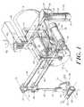
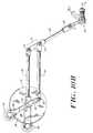
- a user connection element 200is mounted at the end of a link 102.
- the user connection 200is a gimbal assembly that is free to rotate about the axis G 1 defined by an extension of the link 102, being mounted thereon through a suitably frictionless bearing 103.
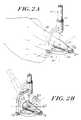
- the gimbal 200is shown in more detail in Fig. 2A.
- a thimble 202is supported by an end quarter-gimbal 204 so that it can spin around an axis G 3 , which passes through one barrel 206 of the end gimbal 204.
- the bearing 203through which the thimble 202 is mounted, is substantially frictionless.
- the quarter-gimbal 204is itself connected through a frictionless bearing 205 to the barrel portion 212 of another, medial quarter gimbal 210.
- the end gimbal 204is free to rotate about axis G 2 , which passes through the barrel portion 212, and which intersects with axis G 3 in the vicinity of the thimble 202.
- the entire gimbal assembly 200made up of the medial quarter gimbal 210 and the end quarter gimbal 204 and the thimble 202 is free to rotate about axis G 1 , which passes through the barrel portion 214 of the medial quarter gimbal 210.
- the axis G 1substantially intersects with the other two axes G 2 and G 3 at a user reference point 222.
- a userinserts a finger 2002 into the thimble 202, the user can rotate the finger about its long dimension, i.e. about axis G 3 .
- the usercan also swing the base of the finger about axis G 1 , thus moving through a plane spanning between the thumb and small finger of an outspread hand, with the palm facing downward.
- the usercan swing the base of the finger about axis G 2 , through a plane spanning between the palm and the back of the hand.
- An aspect of the inventionis the realization that, for many interactions of a user's fingertip and the real world, the environment does not resist motions through these orientation related freedoms defined above. Further, the finger's position with respect to these freedoms is irrelevant to the user's perception of the environment, and for the environment's reaction to the user's finger activities. Essentially, the finger interacts with the world at a point. Thus, it is not necessary to provide apparatus to actively power these freedoms, or, in some cases, to track the user's motions through or position with respect to these freedoms. This aspect of the invention is explained more fully below, after a brief discussion of the apparatus characterized by some powered freedoms of motion and some unpowered freedoms, in a typical embodiment.
- the observationextends to interactions between all other of a user's body members, including but not limited to the foot, arm, tongue, head, buttocks, etc., and combinations of powered and unpowered freedoms other than three powered and three unpowered.
- a usermay also have need to use an orifice, including the mouth, for instance in situations of lower limb paralysis.
- the observationalso extends to the interaction between some point type tools (pencil, stylus, scalpel, etc.) and their environments as well as line-type tools (e.g. rat tail file, sword and cane).
- the user connection gimbal 200is supported freely rotationally upon link 102, which is hinged to a pair of parallel links 106 and 104.
- the hinges 108 and 110, joining the link 102 to the parallel links 104 and 106, respectively,are as frictionless as possible.
- the two links 104 and 106are connected to a disk 112 through a mechanism that is shown partially in phantom in Fig. 1 and is explained in more detail below.
- the disk 112is supported through a frame 114 from a base 116, which itself is supported by a grounded support 118.
- the base 116 and frame 114are fixed to each other so that they rotate together through angle ⁇ 1B , about axis B 1 .
- a bearingis provided to rotatably support both, but is not visible in Fig. 1. This bearing is also as frictionless as possible.
- the groundwhich is not shown, is the item which serves as a frame of reference, relative to which all motions and positions of the user connection element is measured.
- the connection elementis the thimble 202.
- the groundis fixed relative to the earth, or the user's local environment. Thus, it may be fixed to the floor, or a wall, or furniture. However, this is not required. Another portion of the user may, in fact be the ground. For instance, the user's head, or hips, or chest may serve as the ground.
- the groundmay itself be observably "floating,” such as a buoy in a body of water, or other fluid, a floating balloon, or a moving vehicle. What is important is that the ground is the reference frame with respect to which motion and position of the connection element is measured.
- connection to the grounded support 118 through the frame 114 and the base 116permits motion of the gimbal user connection assembly 200 around the axis B 1 . Because the joints 108 and 110 are hinged, it is also possible to move the gimbal assembly 200 in a straight line, rather than along an arc, for instance in a straight line parallel to axis y as shown in Fig. 3.
- an actuator 120which can actively control motion around this axis.
- Actuatoris used in this specification to refer to a unit that is either a motor, or otherwise exerts a force.
- the actuatoris often equipped with an encoder also, although, it need not be.
- the actuator 120has a body portion 122 and an axle (not shown) upon which is mounted a capstan 124. If current is provided to the actuator (through wires not shown), the capstan spins on the axis relative to the body portion 122.
- the body portionis rotationally fixed by a support 125, which is fixed to the grounded support 118, so the capstan 124 rotates relative to ground and the body portion remains fixed.
- a cable 126is wrapped around the -capstan and is anchored at either end 128 to the base 116. The cable is routed such that when the capstan 124 rotates, it pulls the cable 126 around it, thus causing the base 116 to rotate. Consequently, the frame 114 and the entire assembly described above also rotate about axis B 1 . Thus, a torque can be applied to the base 116.
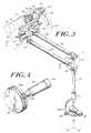
- Fig. 4shows in in detail a single actuator having an encoder 441, a body portion 442 and a capstan 444, connected to a disk 412 through a cable 436.
- This actuator and diskis similar in principal to the three actuators 120, 130 and 140 and their respective disks, as shown in Fig. 1.
- the actuator 120may also provide a position sensing capability.
- the actuator 120includes a conventional position encoder 121 that keeps track of the relative rotary position between the capstan 124 and the body portion 122.
- the position of the base 116 about the axis B 1can be determined and a signal representative thereof can be generated by the encoder.
- any suitable position transducermay be used, such as a potentiometer, a resolver, a hall effect sensor, etc.
- an additional actuator 140is arranged to exert torque on the link 106 around an axis B 2 that passes through the center of the disk 112.
- the body 142 and capstan 144 of the additional actuator 140is connected through a cable 136 to the disk 112 and also includes an encoder, not shown, to keep track of the position of the actuator about the axis B 2 .
- a third actuator 130is also connected to the disk 112 through the same cable 136 and is arranged to exert torque on the link 356 around the axis B 2 .
- the actuator 130also includes an encoder 131 to keep track of the rotational position of another hinge joint (352, Fig. 3, 10A, not shown in Fig. 1) with respect to the axis B 2 .
- the links 106 and 104are parallel, they need not be. Similarly, the links 101 and 356 need not be parallel or of the same length. All that is required is that their relative lengths be known. Hinges are provided between links 104 and 102, 102 and 106 and 106 and 356.
- the links 106 and 356both rotate around an axle bar 354, which is connected to ground by being connected to the disk 112 and the frame 114, which is connected to the grounded support 118. Moving any one link constrains the motion of the other four. However, the motions of the links would not be constrained with respect to ground, but for the axle 354.
- the linkageis a five bar linkage.
- the axle 354can be fixed to one of either links 106 or 356 and can be connected to the disk 112 through a rotary bearing.
- the devicecan determine the location of the user's finger tip.
- the actuators 130 and 140are both connected to the disk 112 through a single cable 136.
- the disk 112is mounted through the frame 114, such that it cannot rotate about the axis B 2 .
- Each actuator 130 and 140is mounted to a respective link 356, 106, such that the body portion of the actuator cannot rotate relative to the link. If current is provided to the actuator (through wires not shown), a relative rotation is induced between the body portion and the respective capstan, for instance the body portion 132 and capstan 134.
- the cable 136is wrapped around the capstan and anchored to the disk 112 at both ends such that when the capstan rotates, it pulls the actuator around the disk, toward one or the other of the cable endpoints.
- the actuator 130it is connected to a relatively short arm 356 which is part of a box frame 355 that pivots around the axle 354 that passes through the center of the disk 112 along the axis B 2 .
- the short link 356extends beyond the center, to a hinged joint 352, at which the link 356 is hinged to the longer link 104.
- the link 356includes a portion 301, which extends from the axle 354 to the hinged joint 352.
- the link 104is connected to the link 102 from which the gimbal user connection assembly 200 is suspended.
- the actuator 140operates similarly. It is also connected to the disk 112 through the same cable 136 by which the actuator 130 is connected.
- the actuator 140is mounted to one end of the link 106, which pivots around the axle 354 (axis B 2 ) at the center of the disk 112. (The link 106 extends beyond the axle 354 to the actuator 140 by virtue of an "L" shaped link extension portion 306.)
- the link 106is also connected through the hinge 110 to the end of the link 102, to which the gimbal assembly 200 is connected.
- the actuator 140will be urged to travel around the perimeter of the disk 112, resulting in the motion of the gimbal assembly 200 from the home position to that shown in Fig. 10C.
- the precise position relative to the groundcan be determined of the user reference point 222 within the thimble where the axes G 1 , G 2 and G 3 intersect.
- This locationcan be used by other parts of a system. For instance, it can be used to determine the location of a mapping of the user's fingertip relative to a virtual environment in a computer. It could also be used to determine the user's intention as to where to move a slave device located in a non-local environment relative to locations in that non-local environment.
- the embodiment discussed aboveemploys linkages that result in three powered, tracked freedoms of motion and three free (unpowered and untracked) freedoms of motion for the user's finger tip.
- a powered freedom of motionit is meant that the mechanism can provide a resistance (or assistance) to the user's attempts to exercise that freedom of motion.
- the powered freedomsare also "tracked," meaning that the mechanism can also keep track of the user's position with respect to that freedom.
- a powered freedomcan be either tracked or untracked, although it is typically not beneficial to have an untracked, powered freedom.
- a tracked freedomcan be either powered or unpowered.
- the powered freedomsare governed by the three actuators 120, 130 and 140, which include both motors and encoders. Considering a stationary reference frame as the ground, the three powered freedoms can be considered to relate to the position of the user's fingertip in a three dimensional space, as indicated by the axes x, y and z in Fig. 3.
- none of the three actuators, 120, 130 or 140can individually power motion through any arbitrary combination of the powered freedoms of translation relative to the axes x, y and z. Rather, all act together to both power and track such motion. Similarly, none of the three actuators can individually provide a torque that establishes an arbitrary force vector with respect to these three axes. Again, all act together to establish such a force.
- the free freedoms in this examplecan be considered to define the rotational position of the thimble, with respect to the stationary reference frame.
- the rotational positionis measured with respect to the x, y, z frame translated to the reference point 222, at which the axes G 1 , G 2 and G 3 coincide.
- This translated reference frameis represented in Fig. 2B by the axes a, b and c.
- Such a rotational positionis measured relative to a rotational rest position, for instance one in which the axes G 1 G 2 and G 3 coincide with the axes a, b and c, respectively.
- the G axesare fixed to the apparatus, and change their orientation depending on the relative location of the gimbal elements. For instance, if the user swivels the thimble such that its tip is pointing straight at the link 102, then the axes G 1 and G 3 would coincide. However, the axes a, b and c always remain orthogonal, and at the same orientation with respect to the reference frame having an origin at the origin of the axes x, y and z. The origin of the axes a, b and c moves with the translation of the reference point 222 at which the three G axes intersect.
- the free freedoms of motionare the rotations of the thimble about the axes a, b and c. They are facilitated through: the free spinning of the medial quarter gimbal 212 about the axis G 1 ; the free spinning of the end quarter gimbal 204 about the axis G 2 ; and the free rotation of the thimble 202 about axis G 3 .
- These freedomscorrespond to a combination of swinging the finger from left to right, and from palm to back of hand, and rotation of the finger about its long axis. None of these freedoms can be impeded or aided by the embodiment of the system shown in Fig. 1. In the embodiment shown, none of these freedoms are tracked or powered. Thus, the user's motions through these freedoms are not sensed or recorded or communicated to the non-local environment in any way. Nor does that environment act upon them.
- a principal aspect of the inventionis the realization that significant advantages can be achieved by limiting the number of powered (and in some cases, tracked) freedoms to less than the maximum number that are physically achievable. For instance, it would be technically possible to provide motors and encoders for each of the joints of the gimbal assembly, as well as the rotating thimble, thus providing six powered freedoms for the thimble. However, such an arrangement has drawbacks. Further, it is not necessary to provide so many powered freedoms to provide an apparatus that provides high fidelity force feedback for many useful applications, particularly point-type and line-type applications.
- Any limited torque applied about these two axescan be faithfully modeled as a force, directed either along a line from palm to back of the hand, or from thumb to small finger or a combination thereof.
- the foregoing considerationsapply to such activities as pushing a button, pulling a loop, pushing an object, probing, picking up objects between thumb and finger(s), tapping and scratching, just to name several.
- the translational position of the fingertipis important, but the rotational status of the finger is irrelevant.
- the buttonwill depress in the same manner whether the user contacts the button with the fleshy portion of the finger tip, or with the fingernail portion of the finger (ignoring considerations of friction).
- the buttonwill depress in the same manner no matter what the finger's angular position to the button from left to right (thumb to small finger) or up and down (back of the hand to the palm).
- actuatorsare relatively heavy and usually expensive. Controlling them requires additional computational power and programming. Additional transmissions are required to communicate with the additional actuators. Their weight must be counterbalanced, or otherwise accounted for so that the user does not perceive their existence. This further adds to the complication and bulk of the device. It also limits its ability to respond quickly to motions of the user, thus resulting in a narrower bandwidth than is desired.
- Fig. 1There is another advantage to powering only three freedoms, and to using an arrangement such as shown in Fig. 1, where the user reference point falls within the user's body member connected to the device, in this case, a finger in a thimble.
- This arrangementallows the user to perceive sharp and small objects.
- the user's haptic resolutionis enhanced, because the device acts as if the point of contact is within the user's body member.
- the effectis analogous to the enhanced haptic resolution achieved by removing a bulky glove and contacting an object with skin surface, except that in this case, the haptic resolution is enhanced by making it seem as if the user's muscles and bone are directly exchanging the force, rather than the force being mediated through the skin and intervening flesh.
- the actuatorsmust be sized so that they can create forces that simulate the type of non-local environment sought to be replicated.
- the deviceshould be able to exert a force large enough so that the user can experience the stiffness of a surface without saturating the actuators. This insures that the user will perceive a wall as immovable.
- a high maximum forcewill also enable the device to display impact force transients more accurately (as when a slave device strikes a wall).
- the maximum force that the device can exertshould also be viewed in relation to the back drive friction inherent in the device (discussed below). It is desirable to have a high ratio of maximum force exertable to back drive friction, because a higher ratio translates to a larger dynamic range of forces the device can exert.
- the average maximum exertable force for a human's index fingerhas been estimated to be on the order of 50 newtons and previous studies have suggested that 40 newtons is an appropriate design maximum for a telerobotic handmaster. See generally, P. H. Sutter, J. C. Iatridis and N. V. Thakor, "Response to Reflected-Force Feedback to Fingers in Teleoperations," Proc. of the NASA Conf. on Space Telerobotics , pp. 65-74. NASA JPL, January 1989.
- a lower force capabilityprovides acceptable performance. For instance, an actuator that can exert a maximum force of only 8 newtons can be used in a system that can create the illusion of a solid wall.
- using smaller actuatorspermits faster response, higher bandwidth, and more flexibility in counterbalancing. It also minimizes the risk of harm or discomfort to the user. Using smaller actuators also facilitates meeting two additional desirable design criteria, that of minimizing back drive friction and of reducing the inertia of the device.
- the deviceshould have as little back drive friction as possible. Friction adds noise to the forces that the device attempts to present (reflect) to the user. It also creates a cue to the user that the non-local world is not natural. Significant friction can cause user fatigue. As has been mentioned above, it is desirable for the ratio of maximum force to back drive friction to be as high as possible to facilitate a wide dynamic range. Therefore, it is desirable for the friction to be as low as possible, particularly since it is also desirable to minimize the maximum exertable force needed.
- frictioncan come from at least three sources: the bearings in the structure, the transmission from the actuators to the linkage, and the actuators themselves.
- the friction in the bearings and the transmissioncan be made very low. Therefore, the actuator technology places a lower limit on the friction that can be achieved, and thus, the upper limit on the ratio of maximum force to back drive friction.
- the ratio of maximum force to friction forcemay be fixed by a choice of actuators, the particular operating range of the forces is determined by the transmission ratio.
- the deviceshould also have a low inertia.
- the inertia of the devicewill not cause a significant problem if the user moves at a constant velocity. However, if the user accelerates or decelerates, the inertia of the system that is not an aspect of a physical system will give the user the undesirable sensation that an external mass is being borne by the user. Additionally, the inertia of the device also limits the bandwidth with which the device can respond to commands. Typically, all devices are capable of providing small forces rather slowly, or at steady state. Thus, it is the ability of the device to provide a relatively large force quickly that determines the bandwidth.
- the apparent mass felt by a user wearing the deviceis proportionally related to the inertia of the structure plus the reflected inertia of the motor.
- the reflected inertia of the motor armatureis proportional to the transmission ratio, N, squared.
- the deviceshould be statically balanced at all points within its operating space. As with friction, an external force created by gravity acting on some unbalanced portion of the device can pollute the forces that the user experiences. Also, a constant offset in force can quickly lead to fatigue for the user. It is possible to actively compensate for imbalances in mechanical structure, however, this requires compromising the dynamic range of the actuators in the system. It is desirable for the balance to be maintained through a wide range of orientations with respect to ground. For example, as discussed below, the embodiment of the invention shown in Fig. 1 is statically balanced within 10 grams whether the base 116 is located gravitationally above or below the user connection gimbal 200.
- the backlashintroduces a discontinuity in the force transmitted from the motors to the user contact assembly. While in the zone of backlash, the user does not feel the load of the motor on the other end of the transmission. However, as the user or the motor moves the device out of the backlash zone, a stiff transition is experienced as the motor is once again engaged. The non-linearities introduced by backlash also tend to destabilize some servo algorithms.
- the stiffness of the structure, transmission and the servo control loopdetermine the overall stiffness and bandwidth of the device.
- the stiffness of the structure and transmissioncan be made very high. Therefore, the limiting stiffness for the device disclosed is the servo-loop.
- the maximum closed loop stiffness achievable with the stable servo-loopis a function of the inertia of the device, the impedance of the user's finger attached to the device the transmission ratio, the servo rate and the encoder resolution.
- the transmission ratiois the easiest of these factors to vary.
- the position resolution of the deviceshould be high, for two reasons. First, a high resolution enables the device, to reflect finer position details of a virtual environment. Second, the resolution of the encoders sets a limit on the stiffness of the control loop which can be closed and similarly limits the generation of viscous and inertial effects.
- a preferred embodiment of the inventionaccommodates the conflicting specification needs of the haptic system, discussed above. It uses three powered, tracked freedoms of motion and three free freedoms of motion. As has been discussed above, this provides for a faithful rendition of the interaction between a user's finger tip and the real world for a wide variety of finger activities.
- the devicecan exert and resist a Cartesian force vector with the user's finger, by using the motors to exert a torque upon the device joints.
- a data processing unitshown schematically in Fig.
- the devicehas the first actuated joint located generally above the location of the user's wrist during use, and the sizes of the other elements allow users to move the wrist, knuckle and finger joints to all extremes without exceeding the workspace of device.
- the base disk portion 116has a diameter of 4.5 in. (11.43 cm.).
- the disk 112has a diameter of 3 in. (7,62 cm.).
- the length of the links between axis B 2 and hinge 110is 5.5 in. ((13.97 cm.) and the length of the link between the hinge 110 and the intersection point 222 is 5.5 in. (13.97 cm.) and the distance between the hinges 110 and 108 is 1.25 in. (3.175 cm.).
- Suitable actuatorsweighing 130 grams, with a peak torque of 24 newton-centimeters, are available from Maxon, Inc., of Switzerland, under trade designation RE025-055-35EBA 201A.
- the motorsuse an ironless armature technology, which reduces torque ripple and minimizes the armature inertia.
- a high resolution encoder suitable for use with the selected actuatorprovides 2,000 counts per rotation, and is available from Hewlett-Packard of Palo Alto, CA under model number 5310.
- gear reduction transmissions availableare subject to greater backlash than desired, as set forth above.
- a "direct-drive”may be used in certain circumstances. However, this requires using motors with a high stall torque. This would require using excessively large, heavy motors, which would result in large inertia and a generally bulky apparatus.
- a direct drive systemhas drawbacks.
- a system that simulates interaction with a larger member, for instance a user's fist, or footsuch a drive may be suitable.
- a cable transmissioncan meet the zero backlash specification with very little friction, and can also provide a transmission reduction.
- the backlashcan be made zero by pretensioning the cable.
- Use of a cable transmissionrequires consideration of several factors.
- the cable routingshould be such that radial forces on motor and capstan bearings are minimized. Cables that are wrapped around pulleys more than one full turn require a finite capstan width, because they "walk" across the capstan as it spins.
- the tension which a drive capstan can maintain on a cableis proportional to e ⁇ where ⁇ is the coefficient of friction between the cable and the capstan and ⁇ is the angle through which the cable is wrapped around the capstan.
- Cableshave a finite minimum pulley radius around which they may travel without creating friction and being significantly fatigued. For instance, for cables sold by Sava corporation under trade designation ST-2032, suitable for use with the embodiment described above, .028 inches (0.71 mm) in diameter, the minimum radius is 0.2 in. (5.08 mm). Transmissions should avoid excessive free lengths of cables over long spans. Long lengths of free cables introduce compliance into the transmission. Further, pretensioned lengths of cables act as energy sources, which can lead to unwanted resonances at certain frequencies. Finally, it is often helpful to add a spiral groove to capstans. This insures that the cable travels in the same manner each time and that wraps of the cable do not scrape each other. This groove also effectively increases the friction coefficient between the cable and capstan, as well as also reducing the fatigue in the cable, both of which are desirable.
- the embodiment of the invention shown generally in Fig. 1provides an elegant arrangement by which the elements of the invention counterbalance each other to provide a static balance and to minimize inertia. It also simplifies the transmission.
- the motor 120which actuates with respect to axis B 1 , is stationary with respect to ground, and therefore, it does not contribute to the inertia of the device.
- the base 116which forms part of the transmission with the actuator 120, does contribute to the inertia of the device around axis B 1 . Therefore, it is beneficial in some instances to remove a portion (for instance, one half) of the disk that is not necessary for the transmission, in order to reduce the inertia.
- Such a configurationmay not be balanced for all orientations, and therefore, it is not beneficial to use a partial disk in all situations.
- the location of the two actuators 130 and 140which cooperate to actuate motion in a plane perpendicular to axis B 2 , act as counterweights to other portions of the assembly so that they substantially balance the structure statically at all points within the workspace. (Actually, the device is statically balanced to within 10 grams at all locations.)
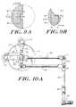
- the means by which the counterbalance is achievedcan be seen with reference to Figs. 10A, 10B and 10C.
- the center of mass of the actuators 130 and 140, the links upon which they are carried, 356 and 106, the link 104, which is parallel to link 106, and the link 102 and gimbaled user contact assembly 200remains at the axis B 2 .
- actuator 140is also kept stationary. If, at the same time, the gimbal assembly 200 is moved (as viewed in Fig. 10A) generally counter clockwise around axis B 2 , to the position shown in Fig.
- the link 104 and the short link 356move such that the actuator 130 is drawn counter clockwise around the disk 112 and the axis B 2 .
- the lengths of the links and their massesare selected such that for a given relative motion, which is governed by the geometry of the links, the center of mass remains substantially at the axis B 2 .
- motions of the gimbaled assembly 200 that cause rotation of the long shaft 106 around axis B 2such as is shown in Fig. 10C, cause a corresponding motion of the actuator 140 around the same axis B 2 , substantially counterbalancing the weight of the portions of the assembly on the other side of the axis B 2 .
- only one cable 136is used for both of the actuators 130 and 140. This has the advantage that it is necessary to install and pretension only a single cable for the two actuators. Further, the cable is routed so that pretensioning adds minimal axial and radial loads to the motor bearings.
- the size of the drive capstans and the size of the shared pulley 112, upon which both the actuators 130 and 140 drive,are determined by several factors. Their relative sizes are chosen to maximize the reduction ratio, while still satisfying the following constraints.
- the shared pulley 112must be large enough so that the actuators can move within 30 degrees of each other without touching. This pulley 112 may not, however, be so large, that it blocks the user's hand during normal use. It is also advantageous to keep the size of this pulley small, so that the rotational inertia of the two actuators and their transmissions about the base axis B 1 is small.
- capstans 144 and 134 of the minimum allowable size(discussed above) of 0.4 in (1.02 cm) and a disk 112 with a radius of 3 in (7.62 cm) results in a transmission ratio between the disk 112 and the capstans (134 or 144) of 7.5:1.
- the torque about the axis B 2is 7.5 times larger than the torque exerted by either actuator.
- the range of motion of the devicemust be adjusted so that the static balance is achieved, given the sizing of the pulley 112.
- a slightly larger reductionis used, for two reasons.
- the inertia about the base axisis considerably larger than about the other two axes, B 2 and B 3 .
- the larger reductionis used for the larger inertia so that the bandwidth about the base axis is comparable to the bandwidth about the other two axes.
- the friction in the bearings of the structurewas higher than that caused by the motor for this axis, so increasing the transmission ratio would not increase the back drive friction considerably. Therefore, the transmission ratio for the base axis may reasonably be from approximately 8.75:1 to 11:1.
- the maximum exertable force with the contact gimbal 200 located at the center of the workspaceis approximately 8.5 newtons along the axes parallel to the long link 106 and the pendulum link 102, when so positioned. Due to the slightly higher transmission ratio, the maximum exertable force around axis B 1 is 9.5 newtons.
- the apparent mass as felt by the useris not constant at all points within the workspace, due to geometric changes as the device moves. Typically, the apparent mass in any direction is between 60 and 95 grams.
- the deviceis statically balanced to within 10 grams for all points within the workspace. If desired, this imbalance can be compensated with the actuators.
- Figs. 9A and 9BThe shape of the workspace available for the embodiment shown in Fig. 1 is shown in Figs. 9A and 9B.
- the size of the workspacewill depend on the general scale of the linkages.
- the dimension of the workspace shown in Figs. 9A and 9B as a crosshatched half circlecan actually be an entire circle, as shown in chain-dotted line, if the user is free to rotate fully. In such a case, special accommodation may be required for any wires that are used to deliver current to the actuators.
- x and yas shown in Fig. 3, or Figs. 9A and 9B
- a singularityarises, and the apparent mass of the device in the x and y directions approaches infinity.
- An electro-mechanical device 510 analogous to that described aboveis connected to the human haptic system 512.
- the human haptic systemis the human user's sense of touch.
- the electro-mechanical device 510is connected to the human system 512 through a means that allows transmission of force (F) and position (x) signals in both directions: from human to device and from device to human.
- the communication between the two systemsmay also include torque ( ⁇ ) and angle ( ⁇ ) signals rather than, or in addition to the force and position signals.
- forceincludes within its meaning both linear forces and torques as well as their derivatives.
- positionor “location” includes within its meaning both linear positions and rotational positions, as well as the derivatives thereof of velocity, acceleration, etc.
- the electro-mechanical apparatusincludes an element 502 for direct user connection or contact, such as the thimble 202 shown in Fig. 1. (Another user connection element, a stylus 602 is shown in Fig. 6 and is discussed below.)
- the user connection element 502is connected to a free gimbal 500, through a connection that transmits force and position signals, i.e., a bearing. (This linkage cannot transmit torque or angle signals, although, in the general case, such signals could be transmitted at this point.)
- the gimbal 500is connected to the actuators 540 through a mechanical linkage 506 and a cable transmission 536 that together convert the force and position signals (and perhaps torque and angle signals) to torque and angular signals only.
- the mechanical linkage 506 and the cable transmission 536together also convert torque and angular signals from the actuators to force and position signals (and perhaps torque and angle signals) to be presented to the gimbal 500.
- the actuators discussed above, 120, 130 and 140include rotational position encoders 550 (identified earlier as 121, 131 and 141), which keep track of the relative rotational positions of the axle of the actuators with respect to their respective body.
- This positionis identified by pulse signals, which are transmitted from the encoders 550 of the electromechanical device 510 to encoder readers 562, which are part of an electrical input/output interface, which connects the electromechanical device 510 to a control apparatus 570, typically embodied in a general purpose computer that has been programmed for the purpose at hand. It is also possible to provide a dedicated device, rather than a programmed general purpose computer.
- the pulse signal from each encoderis received by an encoder reader 562, which converts the pulse signal into a signal representative of the angular position of each actuator axle relative to its body.
- the angle signalis transmitted to the control device 570.
- a kinematics analysis unit 572uses the angular positions of the motors, in conjunction with information about the static conformation of the electromechanical device 510, to determine the location in the user's local environment of the user reference point of the connection element 502, or any other portion of the electromechanical device 510 desired.
- the information about the device's static conformationincludes the length and orientation of its various linkages, transmission ratios, etc.
- this user's position signalis transmitted to an entity in the non-local environment.
- the entitymay be a physical slave device in a remote physical environment, or a computer representation of an entity in a virtual, computer environment. It may also be a computer representation of data in such a computer environment, such as the data representing temperatures over time or space.
- the non-local entityis a physical device in a physical environment.
- the signal representative of position transmitted from kinematics analysis unit 572may be representative of the location where the user desires to place a portion of a slave device in the non-local environment.
- Suitable control devicesare provided to move the slave device according to the user's position instruction.
- the slave deviceencounters the environment in such a way that the device experiences a force upon it. This force is measured by instrumentation provided in connection with the slave device, for instance strain gauges, or the current through actuators, and is communicated from the slave environment, typically as an electric signal, back to the control apparatus 570.
- the schematic block 580may be a physical system, comprising a slave device, its environment, and connections to and from it.
- the slave devicecan be a simple, finger like wand, which moves about an enclosed space. When it touches a wall in the slave environment, a signal is generated that relates to the forces between the slave wand and the wall.
- the slave devicecan be identical to the device shown schematically in block 510
- the control apparatus 570includes a Jacobian application unit 574, which converts the electrical signal representing the force in the non-local environment to an electrical signal that represents the torques that the actuators in the local environment must apply to generate a corresponding force signal between the user and the user connection element 502.
- the Jacobian application unitincludes and manipulates information regarding the conformation of the electro-mechanical device, as well as the current position of the user reference point 222. This information is very similar and is related to the information used by the kinematics analysis section 572.
- the torque commandis passed to a Digital to Analog conversion unit 566, which converts the torque command into a current, based on the specifications of the particular actuators being used.
- This currentis typically amplified by a servo amplification unit 564 and is transmitted to the actuators 540 in the electromechanical device 510.
- the current applied to the actuators 540results in a torque between the body and the axle, which either moves the connected linkages, or results in a force being presented to the human user's haptic system 512. The user moves or does not move, depending cn the magnitude of the force and the task being performed.
- the non-local environment 580is a physical environment with a physical slave device. It is also possible for the non-local environment to be a virtual, computer generated environment, with a virtual slave device.
- the non-local environmentcan be a representation of an enclosure, with various objects distributed throughout.
- the slave devicecan be a point that moves throughout the virtual environment, encountering the objects and the enclosures. The position of the moving point in the virtual environment is dictated by the location of the user reference point 222 in the real, physical master environment.
- the virtual environmentrepresented by schematic diagram block 580, generates a force signal, which is returned to Jacobian analysis unit 574 according to the rules under which the virtual environment operates.
- the designermay provide for a force signal to be generated when the point moves to a virtual location at which a virtual object resides.
- the magnitude of the force, and the spatial domain over which it existsdepends on whether the designer wishes to give the perception of an immovable object, a rigid or soft object, etc.
- control unit 570consists of an appropriately programmed general purpose digital computer.
- a Gateway 2000 Intel 80486 based clone of an IBM personal computer, operating at 66 MHzis suitable.
- the electrical interface 560is made up of three twelve bit digital to analog convertors and three current control, servo amplifiers, available from Coply Controls Corp., of Massachusetts, under product designation Model # 303, a power amplifier and other basic electronics for the computer interface.
- the servo loop as described in general abovehas a gain associated with it, and this gain is the primary factor in determining the overall stiffness of the device.
- the rate at which the computer can close a servo loop around the motorsis a significant limiting factor in setting the gain for an embodiment of the invention as has been described.
- a stiffness of 16 newtons/cmis achievable.
- a stiffness of 32 n/cm.can be obtained.
- the factors that contribute to the servo rateare the number of clock cycles required by the program controlling the computer to complete a servo loop, and the processor speed. Increasing the processor speed or decreasing the number of processor cycles required increases the servo rate, and thus the effective stiffness of the device up to a point in processor speed, after which other considerations begin to come into effect.
- the inventionis not limited by the nature of the non-local environment. Any non-local environment may be used in conjunction with the user contact device of the invention.
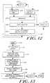
- FIG. 12A schematic block diagram of elements that may be used to provide a user interface with a virtual environment is shown in Fig. 12. Such a device is connected to a hardware apparatus such as shown in Fig. 1 and discussed above.
- the virtual environmentis generated by the force control element 580 shown generally in Fig. 5.
- Fig. 12shows the elements that generate the virtual environment in more detail.
- a geometrical model residence 1230keeps a record of the geometry of the virtual environment.
- the geometryis preestablished.
- the residencestores data with a mathematical representation of the environment, establishing zones, two and three dimensional objects, boundaries, a reference frame, etc. It can be implemented simply in a computer memory or other equivalent device.
- the output of the kinematics analysis element 572is a signal representing the position of a user reference point (or line, as discussed below) of the user apparatus shown in Fig. 1, relative to the reference frame in the user's local environment.
- the user reference pointmay be the intersection 222 of the three G axes.
- the geometrical residence 1230also includes a representation of the reference frame for the user's local environment, and maps that reference frame to some aspect of the virtual environment.
- the output of the kinematics analysis unitis provided to a comparator 1232, which compares the location of the user's reference point or line, with the location of zones and objects, boundaries, etc. in the virtual environment.
- a display device 1238such as a video screen
- a force generator 580Connected to the comparator is a force generator 580, which corresponds to the force generator shown in Fig. 5.
- This componentapplies force related rules based on the characteristics of the virtual environment to the location, (and location derivatives of velocity, acceleration, etc.) of the user reference point, and generates a signal representative of a force. For instance, if the environment is a cubic enclosure with hard walls, if the location of the user reference point is not coincident with any of the walls, the force generator 580 generates a signal representing zero force to be reflected back to the user. However, if the user moves the reference point such that it falls within the space that coincides with a wall, the force generator generates a force signal.
- Fthe force signal
- ka constant
- dthe distance by which the user reference point has passed beyond the plane of the wall before contact.
- the force signalis also passed to a virtual environment reaction calculator 1236, which determines if any changes should be made to the geometrical representation of the virtual environment.
- the zones in the virtual environmentare defined by rules as to how they should transform, if a force is applied to them. For instance, a perfectly rigid wall does not deform, or change at all. Therefore, no matter how much the user tries to push against the location of such a wall, it should not move. Thus, the representation of it should not move, and, the user should feel a force generated each time the user moves the connection point to a location that coincides with the wall.
- the representation of the virtual environmentis also changed to reflect the new position of the wall.
- the zone in which the point is foundcan be a zone representing a movable object, having mass.
- the reaction calculatordetermines the new conformation of the virtual environment and provides this information to the geometry model residence 1230, as well as to a display 1238, if present.
- the inventionalso includes a method of generating a force feedback signal based on making the comparisons between the physical location of the user connection reference point and the virtual environment.
- the steps of this methodare set forth with reference to Fig. 13. These method steps are repeated over and over again, as quickly as the hardware employed can complete all of the calculations and display all that is required.
- the methodbegins at 1310.
- the location of the user pointis received 1312, for instance, from a kinematics analysis unit.
- the location of the user reference pointis related 1314 to the geometry of the virtual environment, by virtue of a mapping of the designer's choosing between the reference frame of the virtual environment and the physical apparatus. It is then determined 1316 in what zone of the virtual environment the mapped user reference point resides. Based on the zone, an appropriate force signal is generated 1318.
- This signaldepends on the particular constitutive relationship for the zone, the location within the zone of the user reference point, as well as the location history, such as velocity, acceleration, etc. This force signal is transmitted to the user apparatus, as has been discussed.
- the constitutive rulesalso govern how the virtual environment should change, based on the location and motions of the user reference point. These necessary changes are calculated at 1320, and the record or image, or representation of the virtual environment is changed accordingly. If a display is being used, the present state of the virtual environment and the user reference point is displayed 1322. The process returns 1324 to the beginning, to get the next location of the user reference point and to again determine the effect between the virtual environment and the user.
- the embodiment that has been describedmodels a point type interaction with its environment, with three active, powered tracked freedoms and three passive, untracked, unpowered freedoms.
- a devicemay be used to interact with any portion of the user's body, such as the finger, hand, head, buttocks, foot, tongue, mouth, etc.
- the size and conformation of the apparatus and the type of connection elementcan be adapted for such use.
- the same combination of freedomsmay also be used in conjunction with a user contact element that is shaped like a stylus, such as is shown at 602 in Fig. 6. Otherwise, the device is identical to that which has been described.
- the usermay grasp the stylus in any appropriate manner.
- itis typically irrelevant to the function of the pen as to how it is rotated relative to its long axis. (This is not true with respect to a fountain pen or a chisel point calligraphy pen.)
- the slave devicecan be a paint brush. It can be real, or virtual. If real, the user will be able to control not only the locations where the paintbrush touches a substrate to be painted, sources of paint, etc. The user will also be able to control the degree to which the brush is pushed toward the substrate after contact has been made, thus spreading out the bristles of the brush and thereby controlling the thickness of the painted line. The user will also be able to feel the effects of paper texture, brush compliance, brush and paper friction, pigment viscosity, etc.
- the designercan provide that the user feels the substrate/stylus combination give away, or spring, analogous to a real paintbrush on painting substrate.
- Such an embodimentcan be implemented using a software program that establishes a plane for the virtual substrate, and notes the position of the user's stylus, and identifies a bristle portion thereof. After the virtual bristle portion contacts the virtual substrate, a spring force is generated in the actuators to simulate the springiness of real bristles, with the force being proportional to the distance moved after virtual contact. The width of the mark made depends on this distance also.
- a bristle brushis a specific implementation of the general class of objects that change their cross-section under a force with a component perpendicular to the plane of the cross-section.
- Othersinclude sponges, felt tip markers, elastomeric erasers, etc. These items are referred to generically as "diagonal"-type items.
- the plane of the virtual substratewith various textures, such as one simulating glass, rough water color paper, canvas, etc.
- the pigment mediumcan be simulated, based on its viscous characteristics. To accomplish this, in addition to the location of the user reference point, its location history must be recorded, since viscous elements have a constitutive relation based on relative velocities.
- the compliance or springiness of a virtual substrate upon which marks are being madecan be simulated, varying between hard surfaces, like a single sheet of paper supported on a metal desk and soft surfaces, like the same piece of paper supported by a stack of paper.
- Textures of surfacescan be modeled in the geometry model, by contacting a user connection device with a physical sample of a selected substrate, and moving the contact device over its surface, thereby generating movement of the user connection device such as would arise if a physical paintbrush (or other tool) were being drawn across a physical substrate. These motions can be recorded, and used to define a virtual surface of the type of the sample. Various types of samples can be thus treated, and a library of surfaces can be obtained.
- Texturescan also be simulated, as a rippled wall, with the ripple dimensions and regularity depending on the texture to be simulated.
- the force generator 1380generates a force based on the springiness of a virtual bristle element that is being compressed and dragged.
- Any situation that can be modeled on a computeris a candidate for use with the interface of the invention.
- the embodiment discussed with reference to Figs. 1 and 6is characterized in general by having a user contact element that is a rigid body, such as the thimble or the stylus.
- the apparatuspowers three freedoms through which the rigid body moves, and also tracks motions through those freedoms. With respect to the other three freedoms of the rigid body, the apparatus neither powers them nor tracks them. However, they are available for the user to move through.
- a rigid body's interaction with the physical worldis described in terms of six freedoms of motion, commonly organized as motions and forces along three orthogonal axes and rotations and torques with respect to three orthogonal axes.
- an important aspect of the inventionis the realization that effective interaction with a physical or virtual environment can be had with a user interface where fewer than all six freedoms of motion of a rigid portion of the connection device are powered.
- the foregoing examplesuse three powered and tracked freedoms and three unpowered, untracked freedoms. It is also possible to track, but not to power the three unpowered freedoms.
- the user contact element 702has a handle 701, similar to a conventional screw driver handle.
- a shaft 703, rigidly fixed to the handleforms, or is rigidly attached to the axle of an actuator 706, the body of which is rigidly held by the arm of the quarter-gimbal 704. Otherwise, the apparatus is configured substantially the same as that shown in Fig. 1.
- the actuator 706is equipped with an internal encoder, just like the actuators 120, 130 and 140 discussed above, so that it can track the rotational location of the handle relative to the body. It is also connected (through electrical cables not shown) to an interface to a control apparatus similar to module 570, which processes the location information generated by the encoder, and generates a torque command, that is translated into a current signal, delivered to the actuator 706 so that it provides an appropriate resistance to the user's motions, given the conditions in a non-local environment. As before, the non-local environment may be physical or virtual.
- This embodimentwould be useful for a user to participate in certain screwdriver type activities. These would include tightening and loosening threaded mechanisms, twirling spaghetti on a fork, etc.
- an position sensor 706which includes an encoder for determining the rotational position of the handle 702, but which does not include a motor to power motions through this freedom.
- This embodimentwould be useful in situations where the position conveys information, but where there is no need to provide a torque feedback to the user. Examples of such situations include where the user makes a selection by rotating a dial to a position that the user verifies visually.
- the advantage to eliminating the motoris that the weight is significantly reduced, and thus the counter balance and inertia considerations are easier to satisfy. Further, if it is not necessary to calculate a torque through this freedom, the control apparatus is simplified.
- FIG. 8Another embodiment of the user connection assembly of the invention is shown schematically with reference to Fig. 8, which shows an assembly having two powered, tracked freedoms and one unpowered, untracked freedom. The remaining portions of the apparatus are substantially the same as that described above, i.e., three other powered and tracked freedoms.
- the user contact element 802 in this caseis a wand. It is connected to the end quarter-gimbal 804 free to rotate about its long axis, just like the stylus described above in connection with Fig. 6.
- An actuator 816is provided, the body of which is rotationally fixed with respect to the link 102 through which it is connected to the rest of the apparatus and ground.
- the axle of the actuator 816is fixed to one end 814 of the medial quarter gimbal 810.
- the other end of the medial quarter gimbal 810is fixed to the body 820 of another actuator 812.
- the axle 824 of this actuator 812is connected to the end 808 of the end quarter gimbal 804, to which the stylus 802 is attached freely rotatably as described.
- This devicecan facilitate the user's interaction with the non-local environment along a line, analogous to the way a blind person uses a cane to identify the location and general size and shape of obstacles in a local environment.
- the personprobes the environment with the cane.
- the canemay encounter objects at any point along the length of the cane, and at any location around the long axis of the cane. It does not matter to the user's perception of the world how the wand itself is situated rotationally with respect to its long axis.
- the environmentreacts in the same way to interactions with the cane regardless of its rotational orientation about its long axis.
- there is a user reference linerather than a user reference point.
- Both of the actuators shown in Fig. 8may include position encoders and motors. However, as discussed above with respect to the screw driver type embodiment certain circumstances may require that only one of the freedoms be powered with a motor, with the other freedom simply tracked with an encoder. Further, it may also be advantageous to provide two position transducers, neither of which have the torque transmitting capacity of an actuator, both providing only an position sensing. Motions of great symphony conductors can be recorded and used to conduct provincial symphony orchestras, either after the fact or in real time.
- the inventionalso contemplates all possible locations for the freedoms that are powered. For instance, in Fig. 7, motion around the long axis of the stylus is powered and motion around the other two axes of the gimbal assembly are not powered. It is also part of the invention if freedom about either of these other two axes alone is the powered freedom, rather than about the axis shown. Similarly, any combination of powering two axes, as shown in Fig. 8 are part of the invention.
- the inventionis shown in Fig. 1 with the location of the user contact assembly 200 generally located gravitationally below the grounded support 118. It can also be used flipped from top to bottom, so that the user contact assembly is above the support 118.
- the devicecan be used in any other orientation, but in some instances, it may be necessary to adjust the shapes and weights of the components that must counterbalance each other, since in some aspects they will balance and in others they will not.
- the "ground”can be any reference frame chosen by the designer. The ground can even be a part of the user's body different from that which connects to the devise at the user reference point 222, or it can be floating, for instance, a buoy in the sea.
- Fig. 11it is also beneficial to use at least two of the devices together, one 1126 manipulated by a user's thumb and the other(s) one (or more) 1122 and 1124, by the other fingers of the same hand. In this manner, the user can grasp objects in the non-local environment between the two or more fingers of the non-local apparatus.
- the use of the quarter-gimbal end assemblyfacilitates this arrangement, since the thimble 202 is only hindered on one side.
- Applications for the inventionare many. They include simulated or remote operation of machinery or musical instruments. For instance, a user could operate a non-local piano with one device attached to each finger of both hands, and to one foot, for the pedal. Pedal operated slave machines can be operated by a user with such an apparatus connected to the foot.
- the devicecan be used by a doctor to probe a bullet wound in a patient at a distant location, searching for bullet fragments. Surgeons can use the device to take "dry runs" of certain procedures, using data from the actual patient. For instance, scans of a patient's head can be taken and provided.
- the two or three dimensional data representing the headis the non-local environment, and is, in fact, a virtual environment, including tumors, wounds, etc.
- a virtual needle probecan navigate through this space, generating force signals that would be appropriate depending on the compliance, mass, motion, etc. of the regions of data. These force signals can be used to provide force feedback to a stylus type user connection apparatus, as shown in Fig. 6, giving a surgeon an idea of what it will feel like to conduct the procedure on the living patient. In this way, the surgeon achieves a "hands on” simulation that may show problems with blockage, obstructions, etc. The surgeon may rely on both the sense of touch and vision to plan a delicate operation.
- the inventioncan be used by attaching one user connection element to each of a user's feet to permit walking through a virtual terrain.
- the inventioncan be used to train a blind person to use a cane in a totally safe environment, simulating potential hazards, like stairs, walls, holes in the ground, etc.
- the inventionas part of a computer interface. For instance, it can be used with the now familiar desk top metaphor for computer files and documents.
- Known interfacestypically use a mouse, with buttons and a trackball.
- the realism of the representation of desk topmay be enhanced with use of the invention.
- the items in the virtual environmentcould be picked up with the invention, in a more realistic way than is now possible.
- the apparatus describedcan give the impression of encountering objects having edges, weights, textures, etc. Pages can be turned by actually grasping. Documents can be moved by nudging, grasping and moving, etc. Larger, or more important files can be made to seem heavier. thicker, etc. Different objects can have different textures, etc.
- a push buttoncan be represented on a computer screen by a perspective view.
- Fkd relation
- a spring resistanceis provided as the switch is moved from side to side, until it crosses a threshold, after which it snaps away.
- Other variations on switches, having multiple positions and engagement and release modesare also possible.
- the actuatorscan be rotary or linear motors, pneumatic devices and any other suitable force or torque transducers.
- connection element between the user and the apparatusmay be tension bearing, compression bearing, or both.
- a loop of stringmay bear tension, but not compression.
- a point or flat platemay bear compression, but not tension.
- a snug fitting thimble, a stylus that is grasped, etc.,may bear both.
- the inventioncan also be used to enhance the usefulness of the display of three dimensional data on a visual display device, such as a computer screen.
- a visual display devicesuch as a computer screen.
- Such datawhen displayed, is often ambiguous, due to the fact that a three-dimensional item is being displayed on a two dimensional medium.
- Using the inventionallows the user to actually feel the configuration of the data in a virtual three dimensional space. Data spanning more than three dimensions can be displayed to the tactile senses by having additional dimensions represented by texture, motion, etc.
- One of the embodiments discussed aboveuses three actuators to power three freedoms. It is also common to power three freedoms using more than three actuators, for instance, if it is desired to give the ability to locate a point and to navigate through obstructions. In such a case, an additional elbow type joint may facilitate circumventing such obstructions. Similarly, more than three free joints may be used to provide three free freedoms.
- the inventionincludes such multi-joint apparati. What is required is that there be a user connection element, and that three freedoms of the user connection element be powered and at least one freedom of the user connection element not be powered.
Landscapes
- Engineering & Computer Science (AREA)
- General Engineering & Computer Science (AREA)
- Theoretical Computer Science (AREA)
- Physics & Mathematics (AREA)
- General Physics & Mathematics (AREA)
- Human Computer Interaction (AREA)
- Automation & Control Theory (AREA)
- Mechanical Engineering (AREA)
- Robotics (AREA)
- Computer Hardware Design (AREA)
- Mathematical Physics (AREA)
- User Interface Of Digital Computer (AREA)
- Position Input By Displaying (AREA)
- Manipulator (AREA)
Description
EP-A-0493795 relates to an active virtual pivot handcontroller using motors to control reflective forces andtorques. Degree of freedom parameters, stops, and reflectiveforce rates may be easily modified without altering hardware.The location of the virtual pivot of the hand controller maybe likewise readily changed.
The present invention is defined by claims 1 to 41 and relateto an apparatus and method for physically exchanging a forcewith a user in a first, user local environment. The apparatuscomprises connection element for physically connecting to abody member of the user; and a means for physically linkingthe connection element to a reference, the linking meanscomprises (i) a means for powering at least three independentfreedoms of the connection element relative to the reference;and (ii) means for maintaining at least two independentfreedoms of the connection element relative to the referenceunpowered.
The method comprises the steps of (a) providing an apparatuscomprising a connection element for physically connecting to abody member of the user and a means for physically linking the connection element to a reference, the linking means comprisesa means for powering at least three independent freedoms ofthe connection element relative to the reference; and (b)means for maintaining at least two independent freedoms of theconnection element relative to the reference unpowered;connecting the connection element to a body member of theuser; powering the at least three independent freedoms of theconnection element.
The
Further, a
| Powered | Not Powered | Not Powered | Not Powered | Not Powered |
| 3P | 3T | 3F | 2T1F | 1T2F |
| 4P | 2T | 2F | 1T1F | |
| 5P | 1T | 1F |
Claims (41)
- An apparatus for physically exchanging a force with auser in a first, user-local environment, said apparatuscomprising:a) a connection element (202) for physically connecting toa body member (2002) of said user; andb) means for physically linking said connection element toa reference (118), said linking means comprising:i) means (120, 130, 140) for powering at least threeindependent freedoms of said connection element(202) relative to said reference (118); andii) means (203, 205) for maintaining at least twoindependent freedoms of said connection element(202) relative to said reference (118) unpowered.
- The apparatus of Claim 1, wherein said means (120, 130,140) for powering said freedoms powers said freedomsbased on a signal generated in a non-local environment(580).
- The apparatus of Claim 1, at least one of said poweredfreedoms comprising a translation relative to saidreference.
- The apparatus of Claim 1, one of said at least twofreedoms that are unpowered comprising a rotation withrespect to said reference.
- The apparatus of Claim 1, said linking means comprisingmeans (120, 130, 140, 816) for powering at least four freedoms of said connection element (202) relative tosaid reference (118).
- The apparatus of Claim 1, said linking means comprisingfirst (103) and second (205) linked orthogonal bearingsand a third bearing (203), which is linked to andorthogonal to one of either the first or second linkedbearings.
- The apparatus of Claim 1, said linking means comprisinga pair of actuators (120, 130) that are movable relativeto each other and relative to a link (112) more proximalto said reference (118) than said pair of actuators(120, 130).
- The apparatus of Claim 1, said linking means comprisingat least two masses (132, 142) that are movable relativeto said reference (118) and each other and saidconnection element (202) so that the centre of massamong said at least two masses and the connectionelement remains substantially stationary relative tosaid reference (118) despite motion of said connectionelement.
- The apparatus of Claim 8, at least one of said masses(132, 142) comprising an actuator.
- The apparatus of Claim 1, said connecting meanscomprising a five bar linkage (102, 104, 106, 356, 354).
- The apparatus of Claim 9, four bars (102, 104, 106, 356)of said five bar linkage defining a plane, said fourbars being connected to said reference, rotatably aboutan axis (B2) perpendicular to said plane.
- The apparatus of Claims 1 or 5, said connecting elementcomprising a thimble (202).
- The apparatus of Claims 1 or 5, said connecting elementcomprising a rod (602).
- The apparatus of Claim 1, said connecting element (202)sized to engage a human finger (2002).
- The apparatus of Claim 1, said connecting element (202)sized to engage a body member of said user selected fromthe group consisting of a human foot, finger, hand,head, buttocks, arm, leg, tongue and toe.
- The apparatus of Claim 1, said linking means furthercomprising:a) means for tracking (121, 131, 141) the motions of saidconnection element (202) relative to said reference(118) with respect to said at least three freedoms thatare powered; andb) means for generating a signal based on said trackedmotions.
- The apparatus of Claim 1, said connection element (202)comprising an element (602) that bears compression.
- The apparatus of Claim 1, said connection element (202)comprising an element (602) that bears tension.
- The apparatus of Claim 1, said connection element (202)comprising means (202) for exchanging an attractiveforce and a repulsive force with said user.
- The apparatus of Claim 1, said means for physicallylinking said connection element to a referencecomprising:a) means (120, 130, 140) for powering threeindependent freedoms of said connection element(202) relative to said reference (118); andb) means (103, 203, 205) for maintaining threeindependent freedoms of said connection element(202) relative to said reference (118) unpowered.
- The apparatus of Claim 2, said apparatus furthercomprising:a) means (550) for tracking said at least three poweredindependent freedoms;b) means (572) for generating a master signal based on saidtracked at least three freedoms; andc) means (570) for communicating said master signal fromsaid means (550) for tracking to said non-localenvironment (580); andd) means (560) for communicating said non-local signal fromsaid non-local environment to said means for powering(120, 130, 140).
- The apparatus of Claim 21, wherein said means (120, 130,140) for powering at least three independent freedomspowers said freedoms to an extent based on said non-localsignal.
- The apparatus of Claim 22, said linking means comprisingmeans (103, 203, 205) for maintaining three independentfreedoms of said connection element (202) relative tosaid reference (118) unpowered.
- The apparatus of Claim 16, further comprising:a) a geometry model (1230) residence for storing arepresentation of:i) a non-local reference frame;ii) a user-local reference frame that corresponds tosaid user-local environment, relative to said non-localreference frame; andiii) the conformation of a non-local environmentcomprising a spring-type element, relative to saidnon-local reference frame;c) a comparator (1232) for comparing the location of a userreference point (222) of the connection element (202)relative to the non-local environment; andd) a force generator (1280) for generating a signalrepresentative of a force, based on the location of theuser reference point (222) relative to the non-localenvironment and a set of force rules (580), includingspring-force rules which specify a spring output forcesignal in response to a location signal of said userreference point (222) indicative of a changedconformation of said spring-type element.
- The apparatus of Claim 24, further comprising a non-localenvironment reaction calculator (1236) that makeschanges to the representation of the conformation of thenon-local environment based on the signal representativeof force and the set of force rules.
- A method for physically exchanging a force between anapparatus and a user in a first, user-local environment,said method comprising the steps of:a) providing an apparatus comprising:i) a connection element (202) for physicallyconnecting to a body member (2002) of said user;andii) means for physically linking said connectionelement to a reference (118), said linking meanscomprising:a) means (120, 130,140) for powering at leastthree independent freedoms of said connectionelement (202) relative to said reference(118); andb) means (203, 205) for maintaining at least twoindependent freedoms of said connectionelement (202) relative to said reference (118)unpowered;b) connecting said connection element to a body member ofsaid user;c) powering (1318) said at least three independent freedomsof said connection element.
- The method of Claim 26, wherein said step of poweringsaid freedoms comprises the step of generating (1318) asignal in a non-local environment and powering saidfreedoms based on said non-local signal.
- The method of Claim 27, comprising the steps of:a) tracking (1312) the location of a user reference pointof said connection element relative to a user referenceframe and generating a signal that corresponds thereto;b) receiving said signal representative of the location ofsaid user reference point;c) storing a representation (1230) of:i) a non-local reference frame;ii) the user reference frame, relative to said non-localreference frame; andiii) the conformation of a non-local environmentcomprising a spring-type element, relative to saidnon-local reference frame;d) comparing (1316) the location of the user referencepoint relative to the non-local environment; ande) generating (1318) a signal representative of a force,based on the location of the user reference pointrelative to the non-local environment and a set of forcerules, including spring-force rules which specify aspring element output force signal in response to alocation signal of said user reference point indicativeof a changed conformation of said spring-type element;andf) changing (1320) the representation of the conformationof the non-local environment based-on the signalrepresentative of force and the set of force rules.
- The apparatus of Claim 6, each bearing (103, 205, 203)having an axis of rotation (G1, G2, G3), said three axesof rotation coinciding at a user reference point (222).
- The apparatus of Claim 29, said connection element (202)comprising a thimble into which said body member (2002)is inserted, said thimble arranged such that said userreference point is within said body member (2002) whenconnected to said thimble.
- The apparatus of Claim 30, said body member comprising afinger (2002).
- The apparatus of Claim 1, said means (130) forpowering comprising at least one ironless armaturemotor powering at least one of the at least three powered degrees of freedom of said connection element(202).
- The apparatus of Claim 32, said means for physicallylinking comprising a plurality of interconnectedlinks (112, 104, 106, 102, 356), at least one (102)of the plurality of interconnected links beingmechanically coupled to said user connection element(202) said apparatus further comprising a cabletransmission (112, 136, 134) mechanically couplingsaid motor (130) to said plurality of interconnectedlinks (112, 104, 106, 102, 356).
- The apparatus of Claim 1, wherein said means forpowering comprises:an actuator (130) powering at least one of the atleast three powered independent degrees of freedom ofsaid user connection element (202); anda cable transmission (112, 136, 134) mechanicallycoupling said actuator (130) to said linkage.
- The apparatus of claim 1, wherein said means forphysically linking further comprises a sensor (706)determining a position of said user connection element(702) relative to the reference (118) with respect to atleast one of the at least two unpowered degrees offreedom.
- The apparatus of Claim 35, wherein said means forpowering (120, 130, 140) powers the at least threepowered degrees of freedom in response to theposition of said user connection element (702) withrespect to the at least one sensed unpowered degreeof freedom.
- The apparatus of Claim 1, wherein said means forphysically linking further comprises a plurality of interconnected links, at least one of the pluralityof interconnected links being mechanically coupled tosaid user connection element, and wherein said meansfor powering further comprises:an actuator (130) powering at least one of the threepowered degrees of freedom of said user connectionelement; anda flexible transmission member (136) mechanicallycoupling said actuator to said plurality ofinterconnected links.
- The apparatus of Claim 37, wherein said actuator(130) is an ironless armature motor.
- The apparatus of Claim 37, wherein said actuator(130) comprises a motor having a capstan (134) withan exterior surface, the exterior surface having agroove extending at least a portion of thecircumference of said capstan, wherein said groove issized and shaped to engage said flexible transmissionmember (136).
- The apparatus of Claim 37, wherein said means forpowering comprises a motor (130) having a capstan(134), and wherein said flexible transmission member(136) extends along at least a portion of a perimeterof one of said plurality of interconnected links andis intracrossed forming a loop, said loop beingengaged on said capstan (134).
- The method of Claim 26, further wherein said meansfor maintaining at least two independent freedomsunpowered comprises means (103, 203, 205) formaintaining three independent freedoms unpowered,said step of powering said at least three independentfreedoms further comprising maintaining three different freedoms of said connection elementunpowered.
Applications Claiming Priority (3)
| Application Number | Priority Date | Filing Date | Title |
|---|---|---|---|
| US130639 | 1993-10-01 | ||
| US08/130,639US5625576A (en) | 1993-10-01 | 1993-10-01 | Force reflecting haptic interface |
| PCT/US1994/010762WO1995010080A1 (en) | 1993-10-01 | 1994-09-22 | Force reflecting haptic interface |
Publications (3)
| Publication Number | Publication Date |
|---|---|
| EP0721615A1 EP0721615A1 (en) | 1996-07-17 |
| EP0721615A4 EP0721615A4 (en) | 1998-10-14 |
| EP0721615B1true EP0721615B1 (en) | 2002-06-05 |
Family
ID=22445632
Family Applications (1)
| Application Number | Title | Priority Date | Filing Date |
|---|---|---|---|
| EP94930465AExpired - LifetimeEP0721615B1 (en) | 1993-10-01 | 1994-09-22 | Force reflecting haptic interface |
Country Status (6)
| Country | Link |
|---|---|
| US (7) | US5625576A (en) |
| EP (1) | EP0721615B1 (en) |
| JP (3) | JP4550945B2 (en) |
| CA (1) | CA2172825C (en) |
| DE (1) | DE69430751T2 (en) |
| WO (1) | WO1995010080A1 (en) |
Cited By (2)
| Publication number | Priority date | Publication date | Assignee | Title |
|---|---|---|---|---|
| DE10352435A1 (en)* | 2003-11-10 | 2005-06-09 | Freter, Elke | Haptic input device for micro-robot, has passive component and actuator with sensors, each including software that detects device configuration based on adjusted angle and length of rotary and linear axes of component and actuator |
| CN108472100A (en)* | 2016-01-26 | 2018-08-31 | 索尼公司 | Grip sense feedback device and stylus formula force feeling feedback device |
Families Citing this family (474)
| Publication number | Priority date | Publication date | Assignee | Title |
|---|---|---|---|---|
| US5889670A (en) | 1991-10-24 | 1999-03-30 | Immersion Corporation | Method and apparatus for tactilely responsive user interface |
| US6801008B1 (en) | 1992-12-02 | 2004-10-05 | Immersion Corporation | Force feedback system and actuator power management |
| US6433771B1 (en) | 1992-12-02 | 2002-08-13 | Cybernet Haptic Systems Corporation | Haptic device attribute control |
| US5629594A (en)* | 1992-12-02 | 1997-05-13 | Cybernet Systems Corporation | Force feedback system |
| US6131097A (en)* | 1992-12-02 | 2000-10-10 | Immersion Corporation | Haptic authoring |
| US7345672B2 (en)* | 1992-12-02 | 2008-03-18 | Immersion Corporation | Force feedback system and actuator power management |
| US5734373A (en) | 1993-07-16 | 1998-03-31 | Immersion Human Interface Corporation | Method and apparatus for controlling force feedback interface systems utilizing a host computer |
| US6057828A (en)* | 1993-07-16 | 2000-05-02 | Immersion Corporation | Method and apparatus for providing force sensations in virtual environments in accordance with host software |
| US6437771B1 (en)* | 1995-01-18 | 2002-08-20 | Immersion Corporation | Force feedback device including flexure member between actuator and user object |
| US5731804A (en)* | 1995-01-18 | 1998-03-24 | Immersion Human Interface Corp. | Method and apparatus for providing high bandwidth, low noise mechanical I/O for computer systems |
| US5805140A (en) | 1993-07-16 | 1998-09-08 | Immersion Corporation | High bandwidth force feedback interface using voice coils and flexures |
| US5739811A (en) | 1993-07-16 | 1998-04-14 | Immersion Human Interface Corporation | Method and apparatus for controlling human-computer interface systems providing force feedback |
| WO1995002801A1 (en) | 1993-07-16 | 1995-01-26 | Immersion Human Interface | Three-dimensional mechanical mouse |
| US5721566A (en)* | 1995-01-18 | 1998-02-24 | Immersion Human Interface Corp. | Method and apparatus for providing damping force feedback |
| US5724264A (en) | 1993-07-16 | 1998-03-03 | Immersion Human Interface Corp. | Method and apparatus for tracking the position and orientation of a stylus and for digitizing a 3-D object |
| US5625576A (en) | 1993-10-01 | 1997-04-29 | Massachusetts Institute Of Technology | Force reflecting haptic interface |
| US5623582A (en)* | 1994-07-14 | 1997-04-22 | Immersion Human Interface Corporation | Computer interface or control input device for laparoscopic surgical instrument and other elongated mechanical objects |
| US5821920A (en) | 1994-07-14 | 1998-10-13 | Immersion Human Interface Corporation | Control input device for interfacing an elongated flexible object with a computer system |
| US20030040361A1 (en) | 1994-09-21 | 2003-02-27 | Craig Thorner | Method and apparatus for generating tactile feedback via relatively low-burden and/or zero burden telemetry |
| US5642469A (en) | 1994-11-03 | 1997-06-24 | University Of Washington | Direct-drive manipulator for pen-based force display |
| US5666138A (en) | 1994-11-22 | 1997-09-09 | Culver; Craig F. | Interface control |
| US6850222B1 (en) | 1995-01-18 | 2005-02-01 | Immersion Corporation | Passive force feedback for computer interface devices |
| US6400352B1 (en) | 1995-01-18 | 2002-06-04 | Immersion Corporation | Mechanical and force transmission for force feedback devices |
| US5691898A (en) | 1995-09-27 | 1997-11-25 | Immersion Human Interface Corp. | Safe and low cost computer peripherals with force feedback for consumer applications |
| US6166723A (en)* | 1995-11-17 | 2000-12-26 | Immersion Corporation | Mouse interface device providing force feedback |
| US7113166B1 (en) | 1995-06-09 | 2006-09-26 | Immersion Corporation | Force feedback devices using fluid braking |
| US6697748B1 (en)* | 1995-08-07 | 2004-02-24 | Immersion Corporation | Digitizing system and rotary table for determining 3-D geometry of an object |
| US5959613A (en)* | 1995-12-01 | 1999-09-28 | Immersion Corporation | Method and apparatus for shaping force signals for a force feedback device |
| US5999168A (en) | 1995-09-27 | 1999-12-07 | Immersion Corporation | Haptic accelerator for force feedback computer peripherals |
| US5754023A (en) | 1995-10-26 | 1998-05-19 | Cybernet Systems Corporation | Gyro-stabilized platforms for force-feedback applications |
| US6639581B1 (en) | 1995-11-17 | 2003-10-28 | Immersion Corporation | Flexure mechanism for interface device |
| US5825308A (en)* | 1996-11-26 | 1998-10-20 | Immersion Human Interface Corporation | Force feedback interface having isotonic and isometric functionality |
| US6704001B1 (en) | 1995-11-17 | 2004-03-09 | Immersion Corporation | Force feedback device including actuator with moving magnet |
| US6100874A (en)* | 1995-11-17 | 2000-08-08 | Immersion Corporation | Force feedback mouse interface |
| US6061004A (en)* | 1995-11-26 | 2000-05-09 | Immersion Corporation | Providing force feedback using an interface device including an indexing function |
| EP0864145A4 (en) | 1995-11-30 | 1998-12-16 | Virtual Technologies Inc | Tactile feedback man-machine interface device |
| US7027032B2 (en)* | 1995-12-01 | 2006-04-11 | Immersion Corporation | Designing force sensations for force feedback computer applications |
| US6028593A (en)* | 1995-12-01 | 2000-02-22 | Immersion Corporation | Method and apparatus for providing simulated physical interactions within computer generated environments |
| US5956484A (en)* | 1995-12-13 | 1999-09-21 | Immersion Corporation | Method and apparatus for providing force feedback over a computer network |
| US6147674A (en) | 1995-12-01 | 2000-11-14 | Immersion Corporation | Method and apparatus for designing force sensations in force feedback computer applications |
| US6169540B1 (en) | 1995-12-01 | 2001-01-02 | Immersion Corporation | Method and apparatus for designing force sensations in force feedback applications |
| US6219032B1 (en)* | 1995-12-01 | 2001-04-17 | Immersion Corporation | Method for providing force feedback to a user of an interface device based on interactions of a controlled cursor with graphical elements in a graphical user interface |
| US8508469B1 (en) | 1995-12-01 | 2013-08-13 | Immersion Corporation | Networked applications including haptic feedback |
| GB9525047D0 (en)* | 1995-12-07 | 1996-02-07 | Philips Electronics Nv | Virtual body control device |
| US6859819B1 (en) | 1995-12-13 | 2005-02-22 | Immersion Corporation | Force feedback enabled over a computer network |
| US6078308A (en)* | 1995-12-13 | 2000-06-20 | Immersion Corporation | Graphical click surfaces for force feedback applications to provide user selection using cursor interaction with a trigger position within a boundary of a graphical object |
| US6300936B1 (en)* | 1997-11-14 | 2001-10-09 | Immersion Corporation | Force feedback system including multi-tasking graphical host environment and interface device |
| US6161126A (en) | 1995-12-13 | 2000-12-12 | Immersion Corporation | Implementing force feedback over the World Wide Web and other computer networks |
| US5691909A (en)* | 1995-12-29 | 1997-11-25 | Western Atlas | Method of virtual machining to predict the accuracy of part to be made with machine tools |
| SE519661C2 (en) | 1996-02-23 | 2003-03-25 | Immersion Corp | Pointing devices and method for marking graphic details on a display with sensory feedback upon finding said detail |
| US5952796A (en)* | 1996-02-23 | 1999-09-14 | Colgate; James E. | Cobots |
| US5923139A (en)* | 1996-02-23 | 1999-07-13 | Northwestern University | Passive robotic constraint devices using non-holonomic transmission elements |
| US6050718A (en)* | 1996-03-28 | 2000-04-18 | Immersion Corporation | Method and apparatus for providing high bandwidth force feedback with improved actuator feel |
| US6111577A (en) | 1996-04-04 | 2000-08-29 | Massachusetts Institute Of Technology | Method and apparatus for determining forces to be applied to a user through a haptic interface |
| US7225404B1 (en)* | 1996-04-04 | 2007-05-29 | Massachusetts Institute Of Technology | Method and apparatus for determining forces to be applied to a user through a haptic interface |
| US6374255B1 (en)* | 1996-05-21 | 2002-04-16 | Immersion Corporation | Haptic authoring |
| EP0842682B9 (en)* | 1996-06-05 | 2005-06-08 | Sega Corporation | Image processor for games |
| US5802353A (en)* | 1996-06-12 | 1998-09-01 | General Electric Company | Haptic computer modeling system |
| US5800179A (en)* | 1996-07-23 | 1998-09-01 | Medical Simulation Corporation | System for training persons to perform minimally invasive surgical procedures |
| US5816105A (en)* | 1996-07-26 | 1998-10-06 | The United States Of America As Represented By The Administrator Of The National Aeronautics And Space Administration | Three degree of freedom parallel mechanical linkage |
| US6125385A (en)* | 1996-08-01 | 2000-09-26 | Immersion Corporation | Force feedback implementation in web pages |
| US6084587A (en)* | 1996-08-02 | 2000-07-04 | Sensable Technologies, Inc. | Method and apparatus for generating and interfacing with a haptic virtual reality environment |
| US6024576A (en)* | 1996-09-06 | 2000-02-15 | Immersion Corporation | Hemispherical, high bandwidth mechanical interface for computer systems |
| US5828197A (en)* | 1996-10-25 | 1998-10-27 | Immersion Human Interface Corporation | Mechanical interface having multiple grounded actuators |
| US6411276B1 (en)* | 1996-11-13 | 2002-06-25 | Immersion Corporation | Hybrid control of haptic feedback for host computer and interface device |
| US6132441A (en) | 1996-11-22 | 2000-10-17 | Computer Motion, Inc. | Rigidly-linked articulating wrist with decoupled motion transmission |
| US7489309B2 (en)* | 1996-11-26 | 2009-02-10 | Immersion Corporation | Control knob with multiple degrees of freedom and force feedback |
| US6636197B1 (en) | 1996-11-26 | 2003-10-21 | Immersion Corporation | Haptic feedback effects for control, knobs and other interface devices |
| US6154201A (en)* | 1996-11-26 | 2000-11-28 | Immersion Corporation | Control knob with multiple degrees of freedom and force feedback |
| US6686911B1 (en) | 1996-11-26 | 2004-02-03 | Immersion Corporation | Control knob with control modes and force feedback |
| US6956558B1 (en) | 1998-03-26 | 2005-10-18 | Immersion Corporation | Rotary force feedback wheels for remote control devices |
| US6128006A (en)* | 1998-03-26 | 2000-10-03 | Immersion Corporation | Force feedback mouse wheel and other control wheels |
| WO1998033136A1 (en)* | 1997-01-27 | 1998-07-30 | Immersion Human Interface Corporation | Method and apparatus for providing high bandwidth, realistic force feedback including an improved actuator |
| WO1998044490A1 (en) | 1997-03-28 | 1998-10-08 | Migaku Takahashi | Magnetic recording medium |
| US6020876A (en) | 1997-04-14 | 2000-02-01 | Immersion Corporation | Force feedback interface with selective disturbance filter |
| US6110130A (en) | 1997-04-21 | 2000-08-29 | Virtual Technologies, Inc. | Exoskeleton device for directly measuring fingertip position and inferring finger joint angle |
| US6050962A (en) | 1997-04-21 | 2000-04-18 | Virtual Technologies, Inc. | Goniometer-based body-tracking device and method |
| US6292170B1 (en) | 1997-04-25 | 2001-09-18 | Immersion Corporation | Designing compound force sensations for computer applications |
| US6285351B1 (en) | 1997-04-25 | 2001-09-04 | Immersion Corporation | Designing force sensations for computer applications including sounds |
| US7472047B2 (en)* | 1997-05-12 | 2008-12-30 | Immersion Corporation | System and method for constraining a graphical hand from penetrating simulated graphical objects |
| EP2345951A3 (en)* | 1997-05-12 | 2013-11-06 | Immersion Corporation | Force-feedback interface device for the hand |
| US6042555A (en) | 1997-05-12 | 2000-03-28 | Virtual Technologies, Inc. | Force-feedback interface device for the hand |
| US6016385A (en)* | 1997-08-11 | 2000-01-18 | Fanu America Corp | Real time remotely controlled robot |
| US6252579B1 (en) | 1997-08-23 | 2001-06-26 | Immersion Corporation | Interface device and method for providing enhanced cursor control with force feedback |
| US6292174B1 (en) | 1997-08-23 | 2001-09-18 | Immersion Corporation | Enhanced cursor control using limited-workspace force feedback devices |
| US5973678A (en)* | 1997-08-29 | 1999-10-26 | Ford Global Technologies, Inc. | Method and system for manipulating a three-dimensional object utilizing a force feedback interface |
| EP2362286B1 (en) | 1997-09-19 | 2015-09-02 | Massachusetts Institute Of Technology | Robotic apparatus |
| US6714839B2 (en)* | 1998-12-08 | 2004-03-30 | Intuitive Surgical, Inc. | Master having redundant degrees of freedom |
| US20040236352A1 (en)* | 1997-09-22 | 2004-11-25 | Yulun Wang | Method and apparatus for performing minimally invasive cardiac procedures |
| US6219589B1 (en)* | 1997-10-22 | 2001-04-17 | Simon Fraser University | Remote manipulator with force feedback and control |
| US6104382A (en) | 1997-10-31 | 2000-08-15 | Immersion Corporation | Force feedback transmission mechanisms |
| US6020875A (en)* | 1997-10-31 | 2000-02-01 | Immersion Corporation | High fidelity mechanical transmission system and interface device |
| US6281651B1 (en) | 1997-11-03 | 2001-08-28 | Immersion Corporation | Haptic pointing devices |
| US6243078B1 (en) | 1998-06-23 | 2001-06-05 | Immersion Corporation | Pointing device with forced feedback button |
| US6211861B1 (en) | 1998-06-23 | 2001-04-03 | Immersion Corporation | Tactile mouse device |
| US6252583B1 (en) | 1997-11-14 | 2001-06-26 | Immersion Corporation | Memory and force output management for a force feedback system |
| US6448977B1 (en) | 1997-11-14 | 2002-09-10 | Immersion Corporation | Textures and other spatial sensations for a relative haptic interface device |
| US6088019A (en)* | 1998-06-23 | 2000-07-11 | Immersion Corporation | Low cost force feedback device with actuator for non-primary axis |
| FR2771202B1 (en)* | 1997-11-19 | 2000-01-21 | Inst Nat Rech Inf Automat | ELECTRONIC IMAGE DATA PROCESSING DEVICE, FOR SIMULATION OF THE DEFORMABLE BEHAVIOR OF AN OBJECT |
| US6256011B1 (en) | 1997-12-03 | 2001-07-03 | Immersion Corporation | Multi-function control device with force feedback |
| US6126373A (en)* | 1997-12-19 | 2000-10-03 | Fanuc Usa Corporation | Method and apparatus for realtime remote robotics command |
| US6191796B1 (en) | 1998-01-21 | 2001-02-20 | Sensable Technologies, Inc. | Method and apparatus for generating and interfacing with rigid and deformable surfaces in a haptic virtual reality environment |
| US6437770B1 (en) | 1998-01-26 | 2002-08-20 | University Of Washington | Flat-coil actuator having coil embedded in linkage |
| US6304091B1 (en) | 1998-02-10 | 2001-10-16 | Immersion Corporation | Absolute position sensing by phase shift detection using a variable capacitor |
| US7713190B2 (en)* | 1998-02-24 | 2010-05-11 | Hansen Medical, Inc. | Flexible instrument |
| US6692485B1 (en) | 1998-02-24 | 2004-02-17 | Endovia Medical, Inc. | Articulated apparatus for telemanipulator system |
| US6197017B1 (en)* | 1998-02-24 | 2001-03-06 | Brock Rogers Surgical, Inc. | Articulated apparatus for telemanipulator system |
| US6554844B2 (en) | 1998-02-24 | 2003-04-29 | Endovia Medical, Inc. | Surgical instrument |
| US8414598B2 (en) | 1998-02-24 | 2013-04-09 | Hansen Medical, Inc. | Flexible instrument |
| US7789875B2 (en)* | 1998-02-24 | 2010-09-07 | Hansen Medical, Inc. | Surgical instruments |
| US20080177285A1 (en)* | 1998-02-24 | 2008-07-24 | Hansen Medical, Inc. | Surgical instrument |
| US20080055241A1 (en)* | 1998-03-26 | 2008-03-06 | Immersion Corporation | Systems and Methods for Haptic Feedback Effects for Control Knobs |
| USH2017H1 (en) | 1998-04-02 | 2002-04-02 | The United States Of America As Represented By The Secretary Of The Air Force | Virtual reality force emulation |
| US6067077A (en)* | 1998-04-10 | 2000-05-23 | Immersion Corporation | Position sensing for force feedback devices |
| US6300938B1 (en) | 1998-04-13 | 2001-10-09 | Immersion Corporation | Multiple-cylinder control device for computers and other electronic apparatus |
| US6233504B1 (en)* | 1998-04-16 | 2001-05-15 | California Institute Of Technology | Tool actuation and force feedback on robot-assisted microsurgery system |
| US6676569B1 (en) | 1998-06-09 | 2004-01-13 | Scott Brian Radow | Bipedal locomotion training and performance evaluation device and method |
| US6429846B2 (en) | 1998-06-23 | 2002-08-06 | Immersion Corporation | Haptic feedback for touchpads and other touch controls |
| US6184868B1 (en) | 1998-09-17 | 2001-02-06 | Immersion Corp. | Haptic feedback control devices |
| US6697043B1 (en) | 1999-12-21 | 2004-02-24 | Immersion Corporation | Haptic interface device and actuator assembly providing linear haptic sensations |
| US6707443B2 (en) | 1998-06-23 | 2004-03-16 | Immersion Corporation | Haptic trackball device |
| US6717573B1 (en) | 1998-06-23 | 2004-04-06 | Immersion Corporation | Low-cost haptic mouse implementations |
| US6421048B1 (en) | 1998-07-17 | 2002-07-16 | Sensable Technologies, Inc. | Systems and methods for interacting with virtual objects in a haptic virtual reality environment |
| US6552722B1 (en) | 1998-07-17 | 2003-04-22 | Sensable Technologies, Inc. | Systems and methods for sculpting virtual objects in a haptic virtual reality environment |
| US6985133B1 (en) | 1998-07-17 | 2006-01-10 | Sensable Technologies, Inc. | Force reflecting haptic interface |
| US6088020A (en)* | 1998-08-12 | 2000-07-11 | Mitsubishi Electric Information Technology Center America, Inc. (Ita) | Haptic device |
| JP3504507B2 (en)* | 1998-09-17 | 2004-03-08 | トヨタ自動車株式会社 | Appropriate reaction force type work assist device |
| US7038667B1 (en)* | 1998-10-26 | 2006-05-02 | Immersion Corporation | Mechanisms for control knobs and other interface devices |
| US7084884B1 (en) | 1998-11-03 | 2006-08-01 | Immersion Corporation | Graphical object interactions |
| US6435794B1 (en)* | 1998-11-18 | 2002-08-20 | Scott L. Springer | Force display master interface device for teleoperation |
| US8527094B2 (en) | 1998-11-20 | 2013-09-03 | Intuitive Surgical Operations, Inc. | Multi-user medical robotic system for collaboration or training in minimally invasive surgical procedures |
| US6951535B2 (en) | 2002-01-16 | 2005-10-04 | Intuitive Surgical, Inc. | Tele-medicine system that transmits an entire state of a subsystem |
| US6659939B2 (en) | 1998-11-20 | 2003-12-09 | Intuitive Surgical, Inc. | Cooperative minimally invasive telesurgical system |
| US6852107B2 (en) | 2002-01-16 | 2005-02-08 | Computer Motion, Inc. | Minimally invasive surgical training using robotics and tele-collaboration |
| US6398726B1 (en) | 1998-11-20 | 2002-06-04 | Intuitive Surgical, Inc. | Stabilizer for robotic beating-heart surgery |
| US6650338B1 (en) | 1998-11-24 | 2003-11-18 | Interval Research Corporation | Haptic interaction with video and image data |
| US6452586B1 (en) | 1998-11-30 | 2002-09-17 | Microsoft Corporation | Computer input device providing tactile feedback |
| US6493608B1 (en)* | 1999-04-07 | 2002-12-10 | Intuitive Surgical, Inc. | Aspects of a control system of a minimally invasive surgical apparatus |
| US6538634B1 (en) | 1998-12-18 | 2003-03-25 | Kent Ridge Digital Labs | Apparatus for the simulation of image-guided surgery |
| US6593907B1 (en) | 1999-01-19 | 2003-07-15 | Mpb Technologies Inc. | Tendon-driven serial distal mechanism |
| GB2347199A (en)* | 1999-02-22 | 2000-08-30 | Haptic Technologies Inc | A hand controller for cursor movement |
| US6781569B1 (en)* | 1999-06-11 | 2004-08-24 | Immersion Corporation | Hand controller |
| WO2000046000A2 (en)* | 1999-02-05 | 2000-08-10 | Pedro Gregorio | Hand controller |
| JP3543695B2 (en) | 1999-03-17 | 2004-07-14 | 富士ゼロックス株式会社 | Driving force generator |
| US6433775B1 (en) | 1999-03-25 | 2002-08-13 | Monkeymedia, Inc. | Virtual force feedback interface |
| US10820949B2 (en)* | 1999-04-07 | 2020-11-03 | Intuitive Surgical Operations, Inc. | Medical robotic system with dynamically adjustable slave manipulator characteristics |
| US6424356B2 (en) | 1999-05-05 | 2002-07-23 | Immersion Corporation | Command of force sensations in a forceback system using force effect suites |
| US7061466B1 (en)* | 1999-05-07 | 2006-06-13 | Immersion Corporation | Force feedback device including single-phase, fixed-coil actuators |
| US6762745B1 (en) | 1999-05-10 | 2004-07-13 | Immersion Corporation | Actuator control providing linear and continuous force output |
| US6903721B2 (en)* | 1999-05-11 | 2005-06-07 | Immersion Corporation | Method and apparatus for compensating for position slip in interface devices |
| US7561142B2 (en) | 1999-07-01 | 2009-07-14 | Immersion Corporation | Vibrotactile haptic feedback devices |
| US8169402B2 (en) | 1999-07-01 | 2012-05-01 | Immersion Corporation | Vibrotactile haptic feedback devices |
| US6693622B1 (en) | 1999-07-01 | 2004-02-17 | Immersion Corporation | Vibrotactile haptic feedback devices |
| DE20022244U1 (en) | 1999-07-01 | 2001-11-08 | Immersion Corp | Control of vibrotactile sensations for haptic feedback devices |
| US6337678B1 (en) | 1999-07-21 | 2002-01-08 | Tactiva Incorporated | Force feedback computer input and output device with coordinated haptic elements |
| AU6754400A (en)* | 1999-07-31 | 2001-02-19 | Craig L. Linden | Method and apparatus for powered interactive physical displays |
| AU1251101A (en)* | 1999-09-09 | 2001-04-10 | Rutgers, The State Of University Of New Jersey | Remote mechanical mirroring using controlled stiffness and actuators (memica) |
| US6564168B1 (en)* | 1999-09-14 | 2003-05-13 | Immersion Corporation | High-resolution optical encoder with phased-array photodetectors |
| US8004229B2 (en)* | 2005-05-19 | 2011-08-23 | Intuitive Surgical Operations, Inc. | Software center and highly configurable robotic systems for surgery and other uses |
| US9517106B2 (en) | 1999-09-17 | 2016-12-13 | Intuitive Surgical Operations, Inc. | Systems and methods for commanded reconfiguration of a surgical manipulator using the null-space |
| DE20080209U1 (en)* | 1999-09-28 | 2001-08-09 | Immersion Corp | Control of haptic sensations for interface devices with vibrotactile feedback |
| US7217240B2 (en)* | 1999-10-01 | 2007-05-15 | Intuitive Surgical, Inc. | Heart stabilizer |
| US6693626B1 (en) | 1999-12-07 | 2004-02-17 | Immersion Corporation | Haptic feedback using a keyboard device |
| US6822635B2 (en) | 2000-01-19 | 2004-11-23 | Immersion Corporation | Haptic interface for laptop computers and other portable devices |
| AU2001232985A1 (en) | 2000-01-25 | 2001-08-07 | Myth Tree Entertainment, Inc. | An electric motor |
| US6377011B1 (en) | 2000-01-26 | 2002-04-23 | Massachusetts Institute Of Technology | Force feedback user interface for minimally invasive surgical simulator and teleoperator and other similar apparatus |
| WO2001064304A1 (en)* | 2000-03-02 | 2001-09-07 | Mythtree, Inc. | A force reflection system |
| JP2001307134A (en)* | 2000-04-19 | 2001-11-02 | Sony Corp | Three-dimensional model processor, its method and program providing medium |
| FR2809048B1 (en)* | 2000-05-18 | 2002-10-11 | Commissariat Energie Atomique | CONTROL ARM |
| US7138976B1 (en) | 2000-07-13 | 2006-11-21 | Rutgers, The State University Of New Jersey | Hand force feedback and sensing system |
| US6906697B2 (en) | 2000-08-11 | 2005-06-14 | Immersion Corporation | Haptic sensations for tactile feedback interface devices |
| AU2001288811A1 (en)* | 2000-09-07 | 2002-03-22 | Neochi Llc | Method and system for simultaneously creating and using multiple virtual realityprograms |
| WO2002023286A1 (en)* | 2000-09-13 | 2002-03-21 | University Of Washington | Time domain passivity control of haptic interfaces |
| US6995744B1 (en) | 2000-09-28 | 2006-02-07 | Immersion Corporation | Device and assembly for providing linear tactile sensations |
| US7182691B1 (en) | 2000-09-28 | 2007-02-27 | Immersion Corporation | Directional inertial tactile feedback using rotating masses |
| US6864877B2 (en) | 2000-09-28 | 2005-03-08 | Immersion Corporation | Directional tactile feedback for haptic feedback interface devices |
| US7084854B1 (en)* | 2000-09-28 | 2006-08-01 | Immersion Corporation | Actuator for providing tactile sensations and device for directional tactile sensations |
| US7249952B2 (en) | 2000-10-03 | 2007-07-31 | President And Fellows Of Harvard College | Methods and apparatus for simulating dental procedures and for training dental students |
| US6668466B1 (en) | 2000-10-19 | 2003-12-30 | Sandia Corporation | Highly accurate articulated coordinate measuring machine |
| WO2002043569A2 (en) | 2000-11-28 | 2002-06-06 | Intuitive Surgical, Inc. | Endoscopic beating-heart stabilizer and vessel occlusion fastener |
| US6867770B2 (en) | 2000-12-14 | 2005-03-15 | Sensable Technologies, Inc. | Systems and methods for voxel warping |
| US6958752B2 (en) | 2001-01-08 | 2005-10-25 | Sensable Technologies, Inc. | Systems and methods for three-dimensional modeling |
| WO2002061523A1 (en)* | 2001-01-30 | 2002-08-08 | Realistix Laboratories Pte Ltd | Multiple degrees of freedom control device |
| US7155673B2 (en) | 2001-02-01 | 2006-12-26 | Ford Global Technologies, Llc | System and method of interactive evaluation of a geometric model |
| US6619960B1 (en)* | 2001-02-06 | 2003-09-16 | Aviation Simulation Trainers, Inc. | Linear control loading system |
| US20020116078A1 (en)* | 2001-02-20 | 2002-08-22 | Best System Inc. | Control method of open type motion simulation system |
| US9625905B2 (en) | 2001-03-30 | 2017-04-18 | Immersion Corporation | Haptic remote control for toys |
| EP1253509A1 (en)* | 2001-04-27 | 2002-10-30 | Jacques Andre | Device for controlling a three-dimensional movement |
| AUPR464601A0 (en)* | 2001-04-30 | 2001-05-24 | Commonwealth Of Australia, The | Shapes vector |
| US20020165524A1 (en)* | 2001-05-01 | 2002-11-07 | Dan Sanchez | Pivot point arm for a robotic system used to perform a surgical procedure |
| US7202851B2 (en)* | 2001-05-04 | 2007-04-10 | Immersion Medical Inc. | Haptic interface for palpation simulation |
| IL143255A (en) | 2001-05-20 | 2015-09-24 | Simbionix Ltd | Endoscopic ultrasonography simulation |
| US6657617B2 (en) | 2001-06-25 | 2003-12-02 | International Business Machines Corporation | Method, apparatus and computer program product for three dimensional text creation |
| US20060178556A1 (en) | 2001-06-29 | 2006-08-10 | Intuitive Surgical, Inc. | Articulate and swapable endoscope for a surgical robot |
| US6817974B2 (en) | 2001-06-29 | 2004-11-16 | Intuitive Surgical, Inc. | Surgical tool having positively positionable tendon-actuated multi-disk wrist joint |
| US7056123B2 (en)* | 2001-07-16 | 2006-06-06 | Immersion Corporation | Interface apparatus with cable-driven force feedback and grounded actuators |
| US7877243B2 (en)* | 2001-07-16 | 2011-01-25 | Immersion Corporation | Pivotable computer interface |
| DE10143291A1 (en)* | 2001-09-04 | 2003-03-20 | Thorsten Kern | Biopsy or injection system consists of an arrangement for applying implements, with an active haptic element which is separated from it spatially and mechanically |
| US6728599B2 (en)* | 2001-09-07 | 2004-04-27 | Computer Motion, Inc. | Modularity system for computer assisted surgery |
| EP1293950A1 (en)* | 2001-09-18 | 2003-03-19 | BRITISH TELECOMMUNICATIONS public limited company | Haptic interface |
| ATE418096T1 (en)* | 2001-10-29 | 2009-01-15 | Albert Schaeffer | INPUT DEVICE USING THE PARALLEL KINEMATIC PRINCIPLE AND WITH HAPTIC FEEDBACK |
| US20030210259A1 (en)* | 2001-11-14 | 2003-11-13 | Liu Alan V. | Multi-tactile display haptic interface device |
| US6839612B2 (en) | 2001-12-07 | 2005-01-04 | Institute Surgical, Inc. | Microwrist system for surgical procedures |
| US6793653B2 (en)* | 2001-12-08 | 2004-09-21 | Computer Motion, Inc. | Multifunctional handle for a medical robotic system |
| EP1472052A2 (en)* | 2002-01-31 | 2004-11-03 | Braintech Canada, Inc. | Method and apparatus for single camera 3d vision guided robotics |
| US7027031B2 (en)* | 2002-02-07 | 2006-04-11 | Gifu University | Touch sense interface and method for controlling touch sense interface |
| TW200304608A (en)* | 2002-03-06 | 2003-10-01 | Z Kat Inc | System and method for using a haptic device in combination with a computer-assisted surgery system |
| US8010180B2 (en) | 2002-03-06 | 2011-08-30 | Mako Surgical Corp. | Haptic guidance system and method |
| US11202676B2 (en) | 2002-03-06 | 2021-12-21 | Mako Surgical Corp. | Neural monitor-based dynamic haptics |
| US7831292B2 (en)* | 2002-03-06 | 2010-11-09 | Mako Surgical Corp. | Guidance system and method for surgical procedures with improved feedback |
| US8996169B2 (en) | 2011-12-29 | 2015-03-31 | Mako Surgical Corp. | Neural monitor-based dynamic haptics |
| US6904823B2 (en) | 2002-04-03 | 2005-06-14 | Immersion Corporation | Haptic shifting devices |
| US7161580B2 (en) | 2002-04-25 | 2007-01-09 | Immersion Corporation | Haptic feedback using rotary harmonic moving mass |
| US7369115B2 (en) | 2002-04-25 | 2008-05-06 | Immersion Corporation | Haptic devices having multiple operational modes including at least one resonant mode |
| US6671651B2 (en)* | 2002-04-26 | 2003-12-30 | Sensable Technologies, Inc. | 3-D selection and manipulation with a multiple dimension haptic interface |
| US7055789B2 (en)* | 2002-05-14 | 2006-06-06 | Automation Tool Company | Articulating tool arm with positional feedback |
| KR100473348B1 (en)* | 2002-06-12 | 2005-03-08 | 한국과학기술연구원 | Method and Device for assembling MEMS Components |
| US7769427B2 (en)* | 2002-07-16 | 2010-08-03 | Magnetics, Inc. | Apparatus and method for catheter guidance control and imaging |
| US7210541B2 (en)* | 2002-09-03 | 2007-05-01 | Microtorq Llc | Transducerized rotary tool |
| US7359746B2 (en)* | 2002-09-09 | 2008-04-15 | Z-Kat, Inc. | Image guided interventional method and apparatus |
| KR101087996B1 (en) | 2002-12-06 | 2011-12-01 | 인튜어티브 서지컬 인코포레이티드 | Minimally invasive surgical instruments |
| AU2003298038A1 (en) | 2002-12-08 | 2004-06-30 | Immersion Corporation | Using haptic effects to enhance information content in communications |
| US8830161B2 (en) | 2002-12-08 | 2014-09-09 | Immersion Corporation | Methods and systems for providing a virtual touch haptic effect to handheld communication devices |
| US8059088B2 (en) | 2002-12-08 | 2011-11-15 | Immersion Corporation | Methods and systems for providing haptic messaging to handheld communication devices |
| AU2002368501A1 (en)* | 2002-12-31 | 2004-07-22 | Massimo Bergamasco | Ekoskeleton interface apparatus |
| US7339574B2 (en)* | 2003-01-16 | 2008-03-04 | Korean Advanced Institute Of Science And Technology | Haptic mouse interface system for providing force and tactile feedbacks to user's fingers and arm |
| US20070166682A1 (en)* | 2003-01-22 | 2007-07-19 | Realsim Systems, Llc. | Medical training apparatus |
| US7997903B2 (en)* | 2003-01-22 | 2011-08-16 | Realsim Systems, Llc | Medical training apparatus |
| FR2850599B1 (en) | 2003-02-05 | 2006-03-03 | Centre Nat Rech Scient | DEVICE FOR MOVING AND ORIENTING AN OBJECT IN THE SPACE AND USE IN RAPID MACHINING |
| EP1452949B1 (en)* | 2003-02-28 | 2009-04-15 | Massimo Bergamasco | Haptic interface device |
| KR100526741B1 (en) | 2003-03-26 | 2005-11-08 | 김시학 | Tension Based Interface System for Force Feedback and/or Position Tracking and Surgically Operating System for Minimally Incising the affected Part Using the Same |
| US8100824B2 (en) | 2003-05-23 | 2012-01-24 | Intuitive Surgical Operations, Inc. | Tool with articulation lock |
| US8562640B2 (en)* | 2007-04-16 | 2013-10-22 | Intuitive Surgical Operations, Inc. | Tool with multi-state ratcheted end effector |
| US8182417B2 (en)* | 2004-11-24 | 2012-05-22 | Intuitive Surgical Operations, Inc. | Articulating mechanism components and system for easy assembly and disassembly |
| US7410483B2 (en)* | 2003-05-23 | 2008-08-12 | Novare Surgical Systems, Inc. | Hand-actuated device for remote manipulation of a grasping tool |
| US8007511B2 (en) | 2003-06-06 | 2011-08-30 | Hansen Medical, Inc. | Surgical instrument design |
| US7476222B2 (en)* | 2003-06-30 | 2009-01-13 | Johnson & Johnson Consumer Companies, Inc. | Methods of reducing the appearance of pigmentation with galvanic generated electricity |
| US7850456B2 (en) | 2003-07-15 | 2010-12-14 | Simbionix Ltd. | Surgical simulation device, system and method |
| USD534777S1 (en) | 2003-09-03 | 2007-01-09 | Microtorq Llc | Rotary mechanized tool |
| JP3783011B2 (en)* | 2003-10-02 | 2006-06-07 | 株式会社日立製作所 | Operation input device, remote operation system, and remote operation method |
| US7280863B2 (en)* | 2003-10-20 | 2007-10-09 | Magnetecs, Inc. | System and method for radar-assisted catheter guidance and control |
| JP4446712B2 (en)* | 2003-10-23 | 2010-04-07 | アルプス電気株式会社 | Haptic input device |
| US7411576B2 (en) | 2003-10-30 | 2008-08-12 | Sensable Technologies, Inc. | Force reflecting haptic interface |
| US7382378B2 (en)* | 2003-10-30 | 2008-06-03 | Sensable Technologies, Inc. | Apparatus and methods for stenciling an image |
| US7095418B2 (en)* | 2003-10-30 | 2006-08-22 | Sensable Technologies, Inc. | Apparatus and methods for texture mapping |
| USD510739S1 (en) | 2003-10-30 | 2005-10-18 | Sensable Technologies, Inc. | Computer interface |
| FR2863069B1 (en)* | 2003-12-02 | 2007-05-18 | Univ Lille Sciences Tech | ISOTONIC INTERFACE FOR ORDERING AN OBJECT, REAL OR VIRTUAL |
| US7889209B2 (en)* | 2003-12-10 | 2011-02-15 | Sensable Technologies, Inc. | Apparatus and methods for wrapping texture onto the surface of a virtual object |
| US7626589B2 (en)* | 2003-12-10 | 2009-12-01 | Sensable Technologies, Inc. | Haptic graphical user interface for adjusting mapped texture |
| FR2863535B1 (en)* | 2003-12-15 | 2009-01-30 | Commissariat Energie Atomique | ACTUATING BLOCK OF A JOINT SEGMENT TRAIN AND MANUAL INTERFACE COMPRISING THE SAME |
| US7149596B2 (en)* | 2004-01-13 | 2006-12-12 | Sensable Technologies, Inc. | Apparatus and methods for modifying a model of an object to enforce compliance with a manufacturing constraint |
| US7283120B2 (en) | 2004-01-16 | 2007-10-16 | Immersion Corporation | Method and apparatus for providing haptic feedback having a position-based component and a predetermined time-based component |
| DE602004006227T2 (en)* | 2004-03-17 | 2008-01-03 | 3Dconnexion Gmbh | User interface device |
| US20050231468A1 (en)* | 2004-04-15 | 2005-10-20 | University Of Northern British Columbia | Methods and systems for interacting with virtual objects |
| US20050252329A1 (en)* | 2004-05-13 | 2005-11-17 | Jean-Guy Demers | Haptic mechanism |
| US7828808B2 (en)* | 2004-06-07 | 2010-11-09 | Novare Surgical Systems, Inc. | Link systems and articulation mechanisms for remote manipulation of surgical or diagnostic tools |
| US7678117B2 (en) | 2004-06-07 | 2010-03-16 | Novare Surgical Systems, Inc. | Articulating mechanism with flex-hinged links |
| US7990374B2 (en)* | 2004-06-29 | 2011-08-02 | Sensable Technologies, Inc. | Apparatus and methods for haptic rendering using data in a graphics pipeline |
| CA2578653A1 (en) | 2004-07-29 | 2006-02-09 | Kevin Ferguson | A human movement measurement system |
| US20060024647A1 (en)* | 2004-07-30 | 2006-02-02 | France Telecom | Method and apparatus for communicating graphical information to a visually impaired person using haptic feedback |
| DE102004040886A1 (en)* | 2004-08-24 | 2006-03-02 | Volkswagen Ag | Operating device for a motor vehicle |
| DE102004049938B4 (en)* | 2004-10-13 | 2006-11-09 | Fraunhofer-Gesellschaft zur Förderung der angewandten Forschung e.V. | Device and method for the simulation of haptic perceptible vibrations of an object |
| US20060106369A1 (en)* | 2004-11-12 | 2006-05-18 | Desai Jaydev P | Haptic interface for force reflection in manipulation tasks |
| ITPI20040084A1 (en)* | 2004-11-18 | 2005-02-18 | Massimo Bergamasco | PORTABLE APTIC INTERFACE |
| US9700334B2 (en) | 2004-11-23 | 2017-07-11 | Intuitive Surgical Operations, Inc. | Articulating mechanisms and link systems with torque transmission in remote manipulation of instruments and tools |
| US7812815B2 (en)* | 2005-01-25 | 2010-10-12 | The Broad of Trustees of the University of Illinois | Compact haptic and augmented virtual reality system |
| EP1851611A1 (en)* | 2005-02-11 | 2007-11-07 | Force Dimension S.à.r.l | Device for transmitting movements and components thereof |
| US8496647B2 (en) | 2007-12-18 | 2013-07-30 | Intuitive Surgical Operations, Inc. | Ribbed force sensor |
| KR100681768B1 (en) | 2005-04-29 | 2007-02-15 | 한국과학기술연구원 | Compact Haptic Device |
| US8027714B2 (en)* | 2005-05-27 | 2011-09-27 | Magnetecs, Inc. | Apparatus and method for shaped magnetic field control for catheter, guidance, control, and imaging |
| WO2007057390A2 (en)* | 2005-11-16 | 2007-05-24 | Abb Ab | Method and device for controlling motion of an industrial robot with a position switch |
| US20070144753A1 (en)* | 2005-12-22 | 2007-06-28 | Microtorq, L.L.C. | Transducerized rotary tool |
| WO2007076068A2 (en)* | 2005-12-22 | 2007-07-05 | Radow Scott B | Exercise device |
| US8628518B2 (en) | 2005-12-30 | 2014-01-14 | Intuitive Surgical Operations, Inc. | Wireless force sensor on a distal portion of a surgical instrument and method |
| US7869854B2 (en)* | 2006-02-23 | 2011-01-11 | Magnetecs, Inc. | Apparatus for magnetically deployable catheter with MOSFET sensor and method for mapping and ablation |
| US8525778B2 (en) | 2007-03-21 | 2013-09-03 | Northwestern University | Haptic device with controlled traction forces |
| US8780053B2 (en)* | 2007-03-21 | 2014-07-15 | Northwestern University | Vibrating substrate for haptic interface |
| US8405618B2 (en)* | 2006-03-24 | 2013-03-26 | Northwestern University | Haptic device with indirect haptic feedback |
| US8209052B2 (en)* | 2006-03-31 | 2012-06-26 | Societe de Commercialisation de Produits de la Recherche Appliquee-Socpra-Sciences et Genie, S.E.C. | High performance differential actuator for robotic interaction tasks |
| KR101384434B1 (en)* | 2006-04-06 | 2014-04-10 | 임머숀 코퍼레이션 | Systems and methods for enhanced haptic effects, and recording medium |
| US8786613B2 (en) | 2006-04-08 | 2014-07-22 | Alan Millman | Method and system for interactive simulation of materials and models |
| WO2007117586A2 (en)* | 2006-04-08 | 2007-10-18 | Allan Millman | Method and system for interactive simulation of materials |
| US20100292706A1 (en)* | 2006-04-14 | 2010-11-18 | The Regents Of The University California | Novel enhanced haptic feedback processes and products for robotic surgical prosthetics |
| WO2007136769A2 (en) | 2006-05-19 | 2007-11-29 | Mako Surgical Corp. | Method and apparatus for controlling a haptic device |
| WO2007136739A2 (en)* | 2006-05-19 | 2007-11-29 | Mako Surgical Corp. | A method and apparatus for controlling a haptic device |
| US7623945B2 (en)* | 2006-05-31 | 2009-11-24 | Kraft Telerobotics, Inc. | Robotic master controller |
| US7783384B2 (en)* | 2006-05-31 | 2010-08-24 | Kraft Brett W | Ambidextrous robotic master controller |
| US9561045B2 (en)* | 2006-06-13 | 2017-02-07 | Intuitive Surgical Operations, Inc. | Tool with rotation lock |
| US7862554B2 (en)* | 2007-04-16 | 2011-01-04 | Intuitive Surgical Operations, Inc. | Articulating tool with improved tension member system |
| US20090201248A1 (en)* | 2006-07-05 | 2009-08-13 | Radu Negulescu | Device and method for providing electronic input |
| US8437535B2 (en) | 2006-09-19 | 2013-05-07 | Roboticvisiontech Llc | System and method of determining object pose |
| US7701161B2 (en) | 2006-10-02 | 2010-04-20 | Honeywell International Inc. | Motor balanced active user interface assembly |
| US8054289B2 (en) | 2006-12-01 | 2011-11-08 | Mimic Technologies, Inc. | Methods, apparatus, and article for force feedback based on tension control and tracking through cables |
| US20080181485A1 (en)* | 2006-12-15 | 2008-07-31 | Beis Jeffrey S | System and method of identifying objects |
| EP2099588B1 (en)* | 2006-12-19 | 2011-10-26 | Deakin University | Method and apparatus for haptic control |
| JP4271232B2 (en)* | 2006-12-20 | 2009-06-03 | ファナック株式会社 | Apparatus, method, program, and recording medium for executing offline programming of robot |
| US9430042B2 (en)* | 2006-12-27 | 2016-08-30 | Immersion Corporation | Virtual detents through vibrotactile feedback |
| US20080163118A1 (en)* | 2006-12-29 | 2008-07-03 | Jason Wolf | Representation of file relationships |
| WO2008087629A2 (en) | 2007-01-16 | 2008-07-24 | Simbionix Ltd. | Preoperative surgical simulation |
| US8543338B2 (en) | 2007-01-16 | 2013-09-24 | Simbionix Ltd. | System and method for performing computerized simulations for image-guided procedures using a patient specific model |
| ES2432083T3 (en) | 2007-02-27 | 2013-11-29 | Carnegie Mellon University | A multi-rod device that has a reinforcing member |
| US20080249395A1 (en)* | 2007-04-06 | 2008-10-09 | Yehoshua Shachar | Method and apparatus for controlling catheter positioning and orientation |
| WO2008129096A1 (en)* | 2007-04-23 | 2008-10-30 | Golden Crab, S.L. | Exoskeleton for safety and control while skiing |
| US8167813B2 (en)* | 2007-05-17 | 2012-05-01 | Immersion Medical, Inc. | Systems and methods for locating a blood vessel |
| US7833135B2 (en)* | 2007-06-27 | 2010-11-16 | Scott B. Radow | Stationary exercise equipment |
| US9285878B2 (en)* | 2007-07-30 | 2016-03-15 | University Of Utah Research Foundation | Shear tactile display system for communicating direction and other tactile cues |
| US9268401B2 (en) | 2007-07-30 | 2016-02-23 | University Of Utah Research Foundation | Multidirectional controller with shear feedback |
| GB0714916D0 (en)* | 2007-07-31 | 2007-09-12 | Wittenstein Aerospace & Simula | Control device |
| US8138895B2 (en)* | 2007-10-19 | 2012-03-20 | Sony Corporation | Force/tactile feedback device |
| US8561473B2 (en) | 2007-12-18 | 2013-10-22 | Intuitive Surgical Operations, Inc. | Force sensor temperature compensation |
| US20110155044A1 (en)* | 2007-12-21 | 2011-06-30 | David Burch | Kinesthetically concordant optical, haptic image sensing device |
| US8326462B1 (en) | 2008-03-12 | 2012-12-04 | University Of Utah Research Foundation | Tactile contact and impact displays and associated methods |
| US8156809B2 (en)* | 2008-03-27 | 2012-04-17 | Immersion Corporation | Systems and methods for resonance detection |
| US20110032090A1 (en)* | 2008-04-15 | 2011-02-10 | Provancher William R | Active Handrest For Haptic Guidance and Ergonomic Support |
| JP4715863B2 (en)* | 2008-05-01 | 2011-07-06 | ソニー株式会社 | Actuator control apparatus, actuator control method, actuator, robot apparatus, and computer program |
| US20090275828A1 (en)* | 2008-05-01 | 2009-11-05 | Magnetecs, Inc. | Method and apparatus for creating a high resolution map of the electrical and mechanical properties of the heart |
| JP4645678B2 (en)* | 2008-05-08 | 2011-03-09 | ソニー株式会社 | Information input / output device, information input / output method, and computer program |
| US8297490B2 (en)* | 2008-05-15 | 2012-10-30 | York Container Company | Materials for and method for manufacturing a container with corner supports and the resulting container |
| US7828077B1 (en) | 2008-05-27 | 2010-11-09 | Jergens, Inc. | Rotary angle tool |
| GB2464147B (en)* | 2008-05-29 | 2013-01-09 | Kevin Knowles | Three degree-of-freedom parallel spherical mechanism for payload orienting applications |
| US8465475B2 (en) | 2008-08-18 | 2013-06-18 | Intuitive Surgical Operations, Inc. | Instrument with multiple articulation locks |
| US10532466B2 (en)* | 2008-08-22 | 2020-01-14 | Titan Medical Inc. | Robotic hand controller |
| US8332072B1 (en) | 2008-08-22 | 2012-12-11 | Titan Medical Inc. | Robotic hand controller |
| CN104887170B (en) | 2008-09-05 | 2017-06-09 | 卡内基梅隆大学 | More piece endoscopic apparatus with spherical distal ends component |
| ES2539521T3 (en)* | 2008-10-10 | 2015-07-01 | Fundacion Fatronik | Universal haptic drive system |
| US8559699B2 (en)* | 2008-10-10 | 2013-10-15 | Roboticvisiontech Llc | Methods and apparatus to facilitate operations in image based systems |
| US8770905B2 (en)* | 2008-11-04 | 2014-07-08 | King Fahd University Of Petroleum And Minerals | Anthropomorphic force-reflective master arm |
| US8457714B2 (en)* | 2008-11-25 | 2013-06-04 | Magnetecs, Inc. | System and method for a catheter impedance seeking device |
| JP5951994B2 (en)* | 2008-12-19 | 2016-07-13 | イマージョン コーポレーションImmersion Corporation | Interactive painting game and associated controller |
| US8610548B1 (en) | 2009-02-03 | 2013-12-17 | University Of Utah Research Foundation | Compact shear tactile feedback device and related methods |
| EP2251767A1 (en) | 2009-05-11 | 2010-11-17 | ETH Zurich | Haptic interface for a virtual environment |
| US20120067354A1 (en)* | 2009-06-03 | 2012-03-22 | Moog B.V. | Skewed-axis three degree-of-freedom remote-center gimbal |
| US20110022078A1 (en)* | 2009-07-23 | 2011-01-27 | Cameron Dale Hinman | Articulating mechanism |
| WO2011025886A1 (en)* | 2009-08-26 | 2011-03-03 | Carefusion 2200, Inc. | Mechanisms for positioning and/or holding surgical instruments and performing other functions, and methods of manufacture and use thereof |
| US20110091853A1 (en)* | 2009-10-20 | 2011-04-21 | Magnetecs, Inc. | Method for simulating a catheter guidance system for control, development and training applications |
| US20110092808A1 (en)* | 2009-10-20 | 2011-04-21 | Magnetecs, Inc. | Method for acquiring high density mapping data with a catheter guidance system |
| US20110112396A1 (en)* | 2009-11-09 | 2011-05-12 | Magnetecs, Inc. | System and method for targeting catheter electrodes |
| US8994665B1 (en) | 2009-11-19 | 2015-03-31 | University Of Utah Research Foundation | Shear tactile display systems for use in vehicular directional applications |
| US8542105B2 (en) | 2009-11-24 | 2013-09-24 | Immersion Corporation | Handheld computer interface with haptic feedback |
| DE102010001084A1 (en)* | 2010-01-21 | 2011-07-28 | Höhne, Jens, Dr., 80331 | Simulator and method for simulating the treatment of a biological tissue |
| CN102200180B (en)* | 2010-03-24 | 2015-02-04 | 鸿富锦精密工业(深圳)有限公司 | Speed reducing mechanism |
| KR101008944B1 (en)* | 2010-03-29 | 2011-01-17 | 한국생산기술연구원 | Lifting device with ring operation |
| US8619064B2 (en) | 2010-04-28 | 2013-12-31 | Microsoft Corporation | Dynamic resistance control of a stylus |
| KR101108145B1 (en)* | 2010-05-07 | 2012-02-06 | 광주과학기술원 | Apparatus and method for implementing a haptic-based network virtual environment supporting high resolution tiled display |
| US8760438B2 (en) | 2010-05-28 | 2014-06-24 | Adobe Systems Incorporated | System and method for simulating stiff bristle brushes using stiffness-height parameterization |
| US8849015B2 (en) | 2010-10-12 | 2014-09-30 | 3D Systems, Inc. | System and apparatus for haptically enabled three-dimensional scanning |
| WO2012073789A1 (en)* | 2010-11-30 | 2012-06-07 | オリンパス株式会社 | Master control input device and master-slave manipulator |
| WO2012074564A1 (en) | 2010-12-02 | 2012-06-07 | Freehand Endoscopic Devices, Inc. | Surgical tool |
| US11314344B2 (en)* | 2010-12-03 | 2022-04-26 | Razer (Asia-Pacific) Pte. Ltd. | Haptic ecosystem |
| US8602456B2 (en) | 2010-12-09 | 2013-12-10 | Harris Corporation | Ball joint having a passageway for routing a cable therethrough |
| US8606403B2 (en) | 2010-12-14 | 2013-12-10 | Harris Corporation | Haptic interface handle with force-indicating trigger mechanism |
| JP5725603B2 (en) | 2010-12-17 | 2015-05-27 | 国立大学法人岐阜大学 | Side-mounted haptic interface |
| US8918215B2 (en) | 2011-01-19 | 2014-12-23 | Harris Corporation | Telematic interface with control signal scaling based on force sensor feedback |
| US8918214B2 (en) | 2011-01-19 | 2014-12-23 | Harris Corporation | Telematic interface with directional translation |
| US8716973B1 (en) | 2011-02-28 | 2014-05-06 | Moog Inc. | Haptic user interface |
| US9205555B2 (en) | 2011-03-22 | 2015-12-08 | Harris Corporation | Manipulator joint-limit handling algorithm |
| US9789603B2 (en) | 2011-04-29 | 2017-10-17 | Sarcos Lc | Teleoperated robotic system |
| US8694134B2 (en) | 2011-05-05 | 2014-04-08 | Harris Corporation | Remote control interface |
| AU2012253797B2 (en)* | 2011-05-06 | 2017-06-22 | Magic Leap, Inc. | Massive simultaneous remote digital presence world |
| US9122325B2 (en) | 2011-05-10 | 2015-09-01 | Northwestern University | Touch interface device and method for applying controllable shear forces to a human appendage |
| US10108288B2 (en) | 2011-05-10 | 2018-10-23 | Northwestern University | Touch interface device and method for applying controllable shear forces to a human appendage |
| US9161771B2 (en) | 2011-05-13 | 2015-10-20 | Intuitive Surgical Operations Inc. | Medical instrument with snake wrist structure |
| US8639386B2 (en) | 2011-05-20 | 2014-01-28 | Harris Corporation | Haptic device for manipulator and vehicle control |
| WO2012177719A2 (en) | 2011-06-21 | 2012-12-27 | Northwestern University | Touch interface device and method for applying lateral forces on a human appendage |
| US8830188B2 (en) | 2011-06-21 | 2014-09-09 | Microsoft Corporation | Infrastructural haptics on wall scale interactive displays |
| CN202135103U (en) | 2011-06-27 | 2012-02-01 | 瑞声声学科技(常州)有限公司 | piezoelectric vibrator |
| CN102320040B (en)* | 2011-08-11 | 2014-02-26 | 南昌大学 | A force-feedback interactive device that independently adjusts its self-weight balance |
| US9026250B2 (en) | 2011-08-17 | 2015-05-05 | Harris Corporation | Haptic manipulation system for wheelchairs |
| CN103987496B (en)* | 2011-08-24 | 2015-05-20 | 山崎马扎克公司 | Nc machine tool system |
| US8931359B2 (en) | 2011-09-19 | 2015-01-13 | Vivero One Research, Llc | Parallelogram based actuating device |
| US8464603B2 (en)* | 2011-09-19 | 2013-06-18 | Vivero One Research, Llc | Parallelogram based actuating device |
| KR101894951B1 (en) | 2011-09-20 | 2018-10-15 | 삼성전자주식회사 | Tactile sense feedback apparatus and method for operating tactile sense feedback apparatus |
| US8996244B2 (en) | 2011-10-06 | 2015-03-31 | Harris Corporation | Improvised explosive device defeat system |
| US9802364B2 (en) | 2011-10-18 | 2017-10-31 | 3D Systems, Inc. | Systems and methods for construction of an instruction set for three-dimensional printing of a user-customizableimage of a three-dimensional structure |
| US9582178B2 (en) | 2011-11-07 | 2017-02-28 | Immersion Corporation | Systems and methods for multi-pressure interaction on touch-sensitive surfaces |
| US9616580B2 (en) | 2012-05-14 | 2017-04-11 | Sarcos Lc | End effector for a robotic arm |
| EP2854687B1 (en) | 2012-06-01 | 2022-08-24 | Intuitive Surgical Operations, Inc. | Systems for avoiding collisions between manipulator arms using a null-space |
| CN107595392B (en) | 2012-06-01 | 2020-11-27 | 直观外科手术操作公司 | Avoidance of manipulator arm collisions with patient using null space |
| EP3915504A1 (en) | 2012-06-01 | 2021-12-01 | Intuitive Surgical Operations, Inc. | Surgical instrument manipulator aspects |
| CN104334109B (en) | 2012-06-01 | 2017-06-23 | 直观外科手术操作公司 | Systems and methods for reconfiguration of commands of a surgical manipulator using null space |
| US9726517B2 (en) | 2012-07-14 | 2017-08-08 | Centre For Imaging Technology Commercialization | Mechanical tracking system |
| US9245428B2 (en) | 2012-08-02 | 2016-01-26 | Immersion Corporation | Systems and methods for haptic remote control gaming |
| US9566173B2 (en)* | 2012-08-02 | 2017-02-14 | Korea University Of Technology And Education Industry-University Cooperation Foundation | Motion control device based on winding string |
| CN102825596B (en)* | 2012-09-13 | 2015-08-12 | 天津大学 | The 6DOF tandem Zhu Shou robot of complete gravitational equilibrium |
| US9727076B2 (en)* | 2012-10-31 | 2017-08-08 | Sarcos Lc | Hand control device for controlling a peripheral system |
| US8954195B2 (en) | 2012-11-09 | 2015-02-10 | Harris Corporation | Hybrid gesture control haptic system |
| EP2928568B1 (en)* | 2012-12-10 | 2019-06-19 | Nanyang Technological University | An apparatus for upper body movement |
| DE102012112247A1 (en) | 2012-12-13 | 2014-06-18 | How To Organize (H2O) Gmbh | Handle element and gripper input module for a haptic input system |
| US20140176661A1 (en) | 2012-12-21 | 2014-06-26 | G. Anthony Reina | System and method for surgical telementoring and training with virtualized telestration and haptic holograms, including metadata tagging, encapsulation and saving multi-modal streaming medical imagery together with multi-dimensional [4-d] virtual mesh and multi-sensory annotation in standard file formats used for digital imaging and communications in medicine (dicom) |
| US8965620B2 (en) | 2013-02-07 | 2015-02-24 | Harris Corporation | Systems and methods for controlling movement of unmanned vehicles |
| US9547366B2 (en) | 2013-03-14 | 2017-01-17 | Immersion Corporation | Systems and methods for haptic and gesture-driven paper simulation |
| EP3014394B1 (en) | 2013-07-05 | 2022-06-22 | Rubin, Jacob A. | Whole-body human-computer interface |
| JP6201126B2 (en)* | 2013-11-07 | 2017-09-27 | 株式会社人機一体 | Master-slave system |
| US9128507B2 (en) | 2013-12-30 | 2015-09-08 | Harris Corporation | Compact haptic interface |
| CN104758053B (en)* | 2014-01-07 | 2018-01-05 | 上银科技股份有限公司 | The contraposition module of the centre of motion point of Minimally Invasive Surgery apparatus |
| US9314922B2 (en) | 2014-02-07 | 2016-04-19 | Control Interfaces LLC | Remotely operated manipulator and ROV control systems and methods |
| KR102237597B1 (en) | 2014-02-18 | 2021-04-07 | 삼성전자주식회사 | Master device for surgical robot and control method thereof |
| JP5946859B2 (en)* | 2014-04-14 | 2016-07-06 | ファナック株式会社 | Robot control device and robot system for robots that move according to force |
| US10766133B2 (en) | 2014-05-06 | 2020-09-08 | Sarcos Lc | Legged robotic device utilizing modifiable linkage mechanism |
| US9372095B1 (en)* | 2014-05-08 | 2016-06-21 | Google Inc. | Mobile robots moving on a visual display |
| EP2990005B1 (en) | 2014-08-31 | 2017-06-21 | Fundacja Rozwoju Kardiochirurgii Im. Prof. Zbigniewa Religi | A manipulator of a medical device |
| GB2531994B (en)* | 2014-10-15 | 2020-06-24 | Cmr Surgical Ltd | Surgical articulation |
| DE102014115600A1 (en) | 2014-10-27 | 2016-04-28 | Karl Storz Gmbh & Co. Kg | Surgical instrument with a manual control device |
| US10123846B2 (en)* | 2014-11-13 | 2018-11-13 | Intuitive Surgical Operations, Inc. | User-interface control using master controller |
| CN118370610A (en) | 2014-11-13 | 2024-07-23 | 直观外科手术操作公司 | Interaction between user interface and master controller |
| KR101643576B1 (en)* | 2015-02-12 | 2016-07-29 | 한국과학기술연구원 | A thimble type force feedback device |
| EP3291891B1 (en) | 2015-04-20 | 2021-01-06 | Schaefer, Michael V. | Apparatus and method for increased realism of training on rowing machines |
| US9833907B1 (en) | 2015-06-22 | 2017-12-05 | X Development Llc | Proximity-based binding |
| US9862099B1 (en) | 2015-06-22 | 2018-01-09 | X Development Llc | Haptic controller with touch-sensitive control knob |
| FR3037841B1 (en) | 2015-06-26 | 2017-08-18 | Haption | ARTICULATED MOTORIZED ARM WITH SAFE CABLE CABESTAN. |
| US9921652B2 (en)* | 2015-06-29 | 2018-03-20 | Apple Inc. | Input with haptic feedback |
| US9535501B1 (en)* | 2015-06-29 | 2017-01-03 | Apple Inc. | Input with haptic feedback |
| WO2017033365A1 (en)* | 2015-08-25 | 2017-03-02 | 川崎重工業株式会社 | Remote control robot system |
| US9971407B2 (en) | 2015-09-30 | 2018-05-15 | Apple Inc. | Haptic feedback for rotary inputs |
| US10589428B1 (en) | 2015-10-01 | 2020-03-17 | Verily Life Sciences Llc | Automatic distribution of control functions between multiple knob controllers based on proximity and relative positioning of the knobs |
| US10201903B1 (en) | 2015-10-22 | 2019-02-12 | Verily Life Sciences Llc | Punch-in / punch-out smoothing for takeover of automated movement with haptic controller |
| US9987753B1 (en) | 2015-10-28 | 2018-06-05 | X Development Llc | Linear force control of rotation of a knob controller |
| US9737987B1 (en) | 2015-11-20 | 2017-08-22 | X Development Llc | Visual cards for describing and loading operational modes to motorized interface element |
| US9811066B1 (en)* | 2015-12-14 | 2017-11-07 | X Development Llc | Throttle functionality of haptic controller |
| JP6507094B2 (en) | 2015-12-28 | 2019-04-24 | 株式会社東芝 | manipulator |
| WO2017152139A1 (en) | 2016-03-04 | 2017-09-08 | Apple Inc. | Input with haptic feedback |
| WO2017156363A1 (en)* | 2016-03-10 | 2017-09-14 | Massachusetts Institute Of Technology | Robotic systems for supporting a user |
| US10248201B2 (en)* | 2016-05-06 | 2019-04-02 | The Board Of Trustees Of The Leland Stanford Junior University | Wolverine: a wearable haptic interface for grasping in virtual reality |
| US11090125B2 (en) | 2016-06-03 | 2021-08-17 | Covidien Lp | Passive axis system for robotic surgical systems |
| CN109195543A (en)* | 2016-06-03 | 2019-01-11 | 柯惠Lp公司 | Passive Shaft Systems for Robotic Surgical Systems |
| JP2018001385A (en)* | 2016-07-08 | 2018-01-11 | ソニー株式会社 | Parallel linkage device, industrial robot, and force indicating apparatus |
| WO2018023736A1 (en)* | 2016-08-05 | 2018-02-08 | SZ DJI Technology Co., Ltd. | System and method for positioning a movable object |
| US9889874B1 (en)* | 2016-08-15 | 2018-02-13 | Clause Technology | Three-axis motion joystick |
| US9823686B1 (en)* | 2016-08-15 | 2017-11-21 | Clause Technology | Three-axis motion joystick |
| US20180075657A1 (en) | 2016-09-15 | 2018-03-15 | Microsoft Technology Licensing, Llc | Attribute modification tools for mixed reality |
| US10919161B2 (en) | 2016-11-11 | 2021-02-16 | Sarcos Corp. | Clutched joint modules for a robotic system |
| US10828767B2 (en) | 2016-11-11 | 2020-11-10 | Sarcos Corp. | Tunable actuator joint modules having energy recovering quasi-passive elastic actuators with internal valve arrangements |
| US10821614B2 (en) | 2016-11-11 | 2020-11-03 | Sarcos Corp. | Clutched joint modules having a quasi-passive elastic actuator for a robotic assembly |
| US10765537B2 (en) | 2016-11-11 | 2020-09-08 | Sarcos Corp. | Tunable actuator joint modules having energy recovering quasi-passive elastic actuators for use within a robotic system |
| CN106444861B (en)* | 2016-11-21 | 2019-05-10 | 清华大学深圳研究生院 | A three-dimensional gesture-based space robot teleoperating system |
| JP7244985B2 (en)* | 2017-05-19 | 2023-03-23 | 川崎重工業株式会社 | Operating device and operating system |
| WO2018212971A1 (en)* | 2017-05-19 | 2018-11-22 | HaptX Inc. | Haptic feedback glove |
| WO2019005945A1 (en) | 2017-06-27 | 2019-01-03 | Massachusetts Institute Of Technology | Wearable robotic systems for supporting a load |
| US10579159B2 (en)* | 2017-11-01 | 2020-03-03 | Dell Products L.P. | Information handling system integrated device actuator monitoring |
| US10579158B2 (en) | 2017-11-01 | 2020-03-03 | Dell Products L.P. | Information handling system predictive key retraction and extension actuation |
| US10675107B2 (en) | 2017-11-15 | 2020-06-09 | Intuitive Surgical Operations, Inc. | Surgical instrument end effector with integral FBG |
| DE102017220996A1 (en)* | 2017-11-23 | 2019-05-23 | Deutsches Zentrum für Luft- und Raumfahrt e.V. | exoskeleton |
| US10843330B2 (en) | 2017-12-07 | 2020-11-24 | Sarcos Corp. | Resistance-based joint constraint for a master robotic system |
| US11331809B2 (en) | 2017-12-18 | 2022-05-17 | Sarcos Corp. | Dynamically controlled robotic stiffening element |
| AT520763B1 (en)* | 2017-12-21 | 2022-09-15 | Hans Kuenz Gmbh | crane control |
| CA3087094A1 (en) | 2017-12-28 | 2019-07-04 | Orbsurgical Ltd. | Microsurgery-specific haptic hand controller |
| US10809804B2 (en) | 2017-12-29 | 2020-10-20 | Haptx, Inc. | Haptic feedback glove |
| CN110166661B (en)* | 2018-02-13 | 2021-03-02 | Oppo广东移动通信有限公司 | Camera Components and Electronics |
| US10775891B2 (en)* | 2018-04-02 | 2020-09-15 | Microsoft Technology Licensing, Llc | Resistance-based haptic device |
| US20190354183A1 (en)* | 2018-05-16 | 2019-11-21 | Immersion Corporation | Kinesthetic feedback to virtual and augmented reality controllers |
| WO2019227032A1 (en) | 2018-05-25 | 2019-11-28 | Intuitive Surgical Operations, Inc. | Fiber bragg grating end effector force sensor |
| WO2020102776A1 (en) | 2018-11-15 | 2020-05-22 | Intuitive Surgical Operations, Inc. | Surgical instrument with sensor aligned cable guide |
| WO2020102778A1 (en) | 2018-11-15 | 2020-05-22 | Intuitive Surgical Operations, Inc. | Strain sensor with contoured deflection surface |
| US11241801B2 (en) | 2018-12-31 | 2022-02-08 | Sarcos Corp. | Robotic end effector with dorsally supported actuation mechanism |
| US11351675B2 (en) | 2018-12-31 | 2022-06-07 | Sarcos Corp. | Robotic end-effector having dynamic stiffening elements for conforming object interaction |
| US10906191B2 (en) | 2018-12-31 | 2021-02-02 | Sarcos Corp. | Hybrid robotic end effector |
| WO2020172547A1 (en) | 2019-02-21 | 2020-08-27 | Radow Scott B | Exercise equipment with music synchronization |
| US11226685B2 (en)* | 2019-06-12 | 2022-01-18 | Microsoft Technology Licensing, Llc | Haptic controller |
| CN110142802A (en)* | 2019-07-02 | 2019-08-20 | 哈尔滨工业大学 | A wire-driven four-bar linkage mechanism |
| CN114423373B (en) | 2019-09-17 | 2025-03-14 | 直观外科手术操作公司 | Compact Differential Coaxial Inductive Force Sensor |
| GB2592862B (en)* | 2019-10-22 | 2024-04-10 | Cmr Surgical Ltd | Console for controlling a robotic manipulator |
| DE102020111179B3 (en)* | 2020-04-24 | 2021-08-12 | Deutsches Zentrum für Luft- und Raumfahrt e.V. | Method for controlling a robot and system |
| US12239393B2 (en) | 2020-05-18 | 2025-03-04 | Intuitive Surgical Operations, Inc. | Hard stop that produces a reactive moment upon engagement for cantilever-based force sensing |
| EP4232886B1 (en) | 2020-10-22 | 2025-09-17 | Haptx, Inc. | Actuator system for force feedback exoskeleton |
| US11833676B2 (en) | 2020-12-07 | 2023-12-05 | Sarcos Corp. | Combining sensor output data to prevent unsafe operation of an exoskeleton |
| US11794345B2 (en) | 2020-12-31 | 2023-10-24 | Sarcos Corp. | Unified robotic vehicle systems and methods of control |
| WO2022232378A1 (en)* | 2021-04-28 | 2022-11-03 | University Of Washington | Perfect plane mechanism |
| US12257014B2 (en) | 2021-06-22 | 2025-03-25 | Intuitive Surgical Operations, Inc. | Devices and methods for crimp interface for cable tension sensor |
| US11826907B1 (en) | 2022-08-17 | 2023-11-28 | Sarcos Corp. | Robotic joint system with length adapter |
| DE102022121635A1 (en)* | 2022-08-26 | 2024-02-29 | Telefónica Germany GmbH & Co. OHG | System, method, computer program and computer-readable medium |
| US11717956B1 (en) | 2022-08-29 | 2023-08-08 | Sarcos Corp. | Robotic joint system with integrated safety |
| WO2024098070A1 (en) | 2022-11-04 | 2024-05-10 | Sarcos Corp. | Robotic end-effector having dynamic stiffening elements with resilient spacers for conforming object interaction |
| US11897132B1 (en) | 2022-11-17 | 2024-02-13 | Sarcos Corp. | Systems and methods for redundant network communication in a robot |
| US11924023B1 (en) | 2022-11-17 | 2024-03-05 | Sarcos Corp. | Systems and methods for redundant network communication in a robot |
Family Cites Families (217)
| Publication number | Priority date | Publication date | Assignee | Title |
|---|---|---|---|---|
| US2475484A (en)* | 1946-05-14 | 1949-07-05 | Nise Dwight Dee De | Method and means for imparting feel back to a manually-movable control element |
| US2906179A (en)* | 1957-01-28 | 1959-09-29 | North American Aviation Inc | Vector gage |
| US3168203A (en)* | 1960-07-07 | 1965-02-02 | Gen Mills Inc | Manually operated hydraulic actuator control having feel-back |
| US3133649A (en)* | 1961-06-30 | 1964-05-19 | Micro Technology Lab Inc | Motion reduction apparatus |
| GB955005A (en)* | 1961-07-21 | 1964-04-08 | Molins Machine Co Ltd | Apparatus for gripping and lifting articles |
| US3139990A (en)* | 1961-12-11 | 1964-07-07 | Central Res Lab Inc | Rugged-duty master-slave manipulator |
| FR1366051A (en)* | 1963-05-09 | 1964-07-10 | Telemecanique Electrique | Multi-directional single lever control device, especially for switches with combined movements |
| US3269826A (en)* | 1963-10-08 | 1966-08-30 | Du Pont | Compaction of finely divided metals |
| US3263824A (en)* | 1963-12-20 | 1966-08-02 | Northrop Corp | Servo controlled manipulator device |
| GB966609A (en)* | 1965-03-10 | 1900-01-01 | ||
| US3350956A (en)* | 1965-07-06 | 1967-11-07 | Gen Dynamics Corp | Six-degree of freedom integrated controller |
| US3409252A (en)* | 1966-09-19 | 1968-11-05 | Nasa Usa | Controllers |
| US3447766A (en)* | 1967-02-14 | 1969-06-03 | Bendix Corp | Control stick with solid state sensors |
| US3449008A (en)* | 1967-06-08 | 1969-06-10 | Gen Dynamics Corp | Object handling system with remote manual control |
| US3531868A (en)* | 1968-04-18 | 1970-10-06 | Ford Motor Co | Surface scanner for measuring the coordinates of points on a three-dimensional surface |
| US3561263A (en)* | 1968-08-08 | 1971-02-09 | Task Corp | Force and moment dynamometer |
| US3618786A (en)* | 1969-01-02 | 1971-11-09 | Gen Electric | Material-handling apparatus with end effector force resolver and feedback |
| DE1919034A1 (en)* | 1969-04-15 | 1970-10-22 | Erdmann Jesnitzer Dr Ing Habil | Device for controlling electric welding processes |
| US3637092A (en)* | 1970-04-30 | 1972-01-25 | Gen Electric | Material-handling apparatus |
| US3620095A (en)* | 1970-09-03 | 1971-11-16 | Nasa | Mechanically actuated triggered hand |
| US3919691A (en) | 1971-05-26 | 1975-11-11 | Bell Telephone Labor Inc | Tactile man-machine communication system |
| US3771037A (en)* | 1973-03-15 | 1973-11-06 | Nasa | Solid state controller three-axes controller |
| DE2401853C2 (en)* | 1974-01-16 | 1982-07-15 | Philips Patentverwaltung Gmbh, 2000 Hamburg | Motor drive for moving a device part on an X-ray examination device |
| US3890958A (en)* | 1974-04-08 | 1975-06-24 | Moog Automotive Inc | Physiological diagnostic apparatus |
| US3944798A (en)* | 1974-04-18 | 1976-03-16 | Eaton-Leonard Corporation | Method and apparatus for measuring direction |
| US3920972A (en)* | 1974-07-16 | 1975-11-18 | Cincinnati Milacron Inc | Method and apparatus for programming a computer operated robot arm |
| US3948093A (en)* | 1975-06-30 | 1976-04-06 | International Business Machines Corporation | Six degree of freedom force transducer for a manipulator system |
| US4062455A (en)* | 1976-11-22 | 1977-12-13 | Flatau Carl R | Remote manipulator |
| GB1595342A (en)* | 1977-06-17 | 1981-08-12 | Teleflex Morse Ltd | Remote control mechanism |
| US4150803A (en)* | 1977-10-05 | 1979-04-24 | Fernandez Carlos P | Two axes controller |
| US4216467A (en)* | 1977-12-22 | 1980-08-05 | Westinghouse Electric Corp. | Hand controller |
| FR2416094A1 (en)* | 1978-02-01 | 1979-08-31 | Zarudiansky Alain | REMOTE HANDLING DEVICE |
| US4221516A (en)* | 1978-05-31 | 1980-09-09 | Central Research Laboratories, Inc. | Master-slave manipulator |
| JPS594266B2 (en)* | 1978-07-28 | 1984-01-28 | 元田電子工業株式会社 | Advanced control robot |
| US4229136A (en)* | 1979-03-19 | 1980-10-21 | International Business Machines Corporation | Programmable air pressure counterbalance system for a manipulator |
| FR2451807A1 (en)* | 1979-03-22 | 1980-10-17 | Renault | SIX AXIS MANIPULATOR |
| US4367532A (en)* | 1979-10-12 | 1983-01-04 | Nordson Corporation | Manually programmable robot with power-assisted motion during programming |
| US4420808A (en)* | 1980-04-01 | 1983-12-13 | United Technologies Corporation | Multi-axis force stick, self-trimmed aircraft flight control system |
| US4638798A (en)* | 1980-09-10 | 1987-01-27 | Shelden C Hunter | Stereotactic method and apparatus for locating and treating or removing lesions |
| JPS57113114A (en)* | 1980-12-30 | 1982-07-14 | Fanuc Ltd | Robot control system |
| FR2512570A1 (en)* | 1981-09-09 | 1983-03-11 | Commissariat Energie Atomique | POST-EFFORT RETURN POSITIONING SYSTEM WITH DELAY IN TRANSMISSION AND ITS APPLICATION TO A TELEMANIPULATOR |
| US4521685A (en)* | 1982-03-01 | 1985-06-04 | Lord Corporation | Tactile sensor for an industrial robot or the like |
| SE431432B (en)* | 1982-06-01 | 1984-02-06 | Saab Scania Ab | MOTORIZED |
| US4477973A (en)* | 1982-07-14 | 1984-10-23 | Micro Control Systems, Inc. | Three dimensional graphics tablet |
| US4593470A (en)* | 1982-07-14 | 1986-06-10 | Micro Control Systems, Inc. | Portable three dimensional graphics tablet |
| US4555960A (en)* | 1983-03-23 | 1985-12-03 | Cae Electronics, Ltd. | Six degree of freedom hand controller |
| US4655673A (en)* | 1983-05-10 | 1987-04-07 | Graham S. Hawkes | Apparatus providing tactile feedback to operators of remotely controlled manipulators |
| US4648782A (en)* | 1983-05-27 | 1987-03-10 | Kraft Brett W | Underwater manipulator system |
| US4604016A (en)* | 1983-08-03 | 1986-08-05 | Joyce Stephen A | Multi-dimensional force-torque hand controller having force feedback |
| US4670851A (en)* | 1984-01-09 | 1987-06-02 | Mitsubishi Denki Kabushiki Kaisha | Vector quantizer |
| JPS60170709A (en)* | 1984-02-16 | 1985-09-04 | Toshiba Corp | Measuring insturment for shape |
| US4571834A (en)* | 1984-02-17 | 1986-02-25 | Orthotronics Limited Partnership | Knee laxity evaluator and motion module/digitizer arrangement |
| US4676002A (en)* | 1984-06-25 | 1987-06-30 | Slocum Alexander H | Mechanisms to determine position and orientation in space |
| JPS61105411A (en)* | 1984-10-29 | 1986-05-23 | Mitsutoyo Mfg Co Ltd | Measuring method of multidimensional measuring machine |
| US4654648A (en)* | 1984-12-17 | 1987-03-31 | Herrington Richard A | Wireless cursor control system |
| JPS61146482A (en)* | 1984-12-20 | 1986-07-04 | 工業技術院長 | Controller for different-structure different freedom-degree bilateral-master/slave-manipulator |
| US4632341A (en)* | 1985-02-06 | 1986-12-30 | The United States Of America As Represented By The Secretary Of The Air Force | Stabilizing force feedback in bio-actuated control systems |
| DE3523188A1 (en)* | 1985-06-28 | 1987-01-08 | Zeiss Carl Fa | CONTROL FOR COORDINATE MEASURING DEVICES |
| US4679331A (en)* | 1985-08-26 | 1987-07-14 | Ppg Industries, Inc. | Apparatus and method for determining contour characteristics of a contoured article |
| US4680519A (en)* | 1985-09-23 | 1987-07-14 | General Electric Co. | Recursive methods for world-to-joint transformation for a robot manipulator |
| US5103404A (en)* | 1985-12-06 | 1992-04-07 | Tensor Development, Inc. | Feedback for a manipulator |
| US4973215A (en)* | 1986-02-18 | 1990-11-27 | Robotics Research Corporation | Industrial robot with servo |
| US5155423A (en) | 1986-02-18 | 1992-10-13 | Robotics Research Corporation | Industrial robot with servo |
| JPH085018B2 (en)* | 1986-02-26 | 1996-01-24 | 株式会社日立製作所 | Remote manipulation method and apparatus |
| US4787051A (en)* | 1986-05-16 | 1988-11-22 | Tektronix, Inc. | Inertial mouse system |
| SU1777207A1 (en)* | 1986-05-19 | 1992-11-23 | Bruss G Univ Im V I Leni | Device for remote transfer of shaft angle of turn |
| US4791934A (en)* | 1986-08-07 | 1988-12-20 | Picker International, Inc. | Computer tomography assisted stereotactic surgery system and method |
| US4945305A (en)* | 1986-10-09 | 1990-07-31 | Ascension Technology Corporation | Device for quantitatively measuring the relative position and orientation of two bodies in the presence of metals utilizing direct current magnetic fields |
| US4849692A (en)* | 1986-10-09 | 1989-07-18 | Ascension Technology Corporation | Device for quantitatively measuring the relative position and orientation of two bodies in the presence of metals utilizing direct current magnetic fields |
| NL8602697A (en)* | 1986-10-27 | 1988-05-16 | Huka Bv Developments | JOYSTICK. |
| US4795296A (en)* | 1986-11-17 | 1989-01-03 | California Institute Of Technology | Hand-held robot end effector controller having movement and force control |
| US4750487A (en)* | 1986-11-24 | 1988-06-14 | Zanetti Paul H | Stereotactic frame |
| CA1299362C (en) | 1986-12-10 | 1992-04-28 | Gregory James Mcdonald | Coordinate measuring system |
| JPH0829509B2 (en)* | 1986-12-12 | 1996-03-27 | 株式会社日立製作所 | Control device for manipulator |
| US4945501A (en)* | 1987-01-20 | 1990-07-31 | The Warner & Swasey Company | Method for determining position within the measuring volume of a coordinate measuring machine and the like and system therefor |
| US4819195A (en)* | 1987-01-20 | 1989-04-04 | The Warner & Swasey Company | Method for calibrating a coordinate measuring machine and the like and system therefor |
| US4800721A (en)* | 1987-02-13 | 1989-01-31 | Caterpillar Inc. | Force feedback lever |
| US4988981B1 (en)* | 1987-03-17 | 1999-05-18 | Vpl Newco Inc | Computer data entry and manipulation apparatus and method |
| US4893981A (en)* | 1987-03-26 | 1990-01-16 | Kabushiki Kaisha Komatsu Seisakusho | Master/slave type manipulator |
| US5018922A (en)* | 1987-03-26 | 1991-05-28 | Kabushiki Kaisha Komatsu Seisakusho | Master/slave type manipulator |
| US4839838A (en)* | 1987-03-30 | 1989-06-13 | Labiche Mitchell | Spatial input apparatus |
| US4961138A (en)* | 1987-05-01 | 1990-10-02 | General Datacomm, Inc. | System and apparatus for providing three dimensions of input into a host processor |
| EP0362255B1 (en)* | 1987-05-01 | 1993-07-14 | General DataComm, Inc. | System and apparatus for providing three dimensions of input to a host processor |
| IT1214292B (en)* | 1987-05-05 | 1990-01-10 | Garda Impianti Srl | EQUIPMENT FOR MEASUREMENT AND / OR CONTROL OF THE POSITION AND ORIENTATION OF POINTS OR AREAS CHARACTERISTIC OF STRUCTURES, IN PARTICULAR OF VEHICLE BODIES. |
| JPH0820894B2 (en)* | 1987-07-01 | 1996-03-04 | 株式会社日立製作所 | Industrial robot operation control method |
| JPS6420282U (en)* | 1987-07-24 | 1989-02-01 | ||
| US4823634A (en) | 1987-11-03 | 1989-04-25 | Culver Craig F | Multifunction tactile manipulatable control |
| DE3740070A1 (en)* | 1987-11-26 | 1989-06-08 | Zeiss Carl Fa | TURN SLEWING DEVICE FOR TEST COOKING OF COORDINATE MEASURING DEVICES |
| GB8729638D0 (en) | 1987-12-19 | 1988-02-03 | Renishaw Plc | Mounting for surface sensing device |
| US4942538A (en)* | 1988-01-05 | 1990-07-17 | Spar Aerospace Limited | Telerobotic tracker |
| US5251127A (en) | 1988-02-01 | 1993-10-05 | Faro Medical Technologies Inc. | Computer-aided surgery apparatus |
| GB8803847D0 (en)* | 1988-02-18 | 1988-03-16 | Renishaw Plc | Mounting for surface-sensing device |
| SE461548B (en)* | 1988-02-18 | 1990-02-26 | Johansson Ab C E | PROCEDURE AND DEVICE FOR DETERMINING AND CORRECTING IN CASE OF LOCATION ERROR IN SEATING A POINT OF A POINT OR POSITIONING TO A POINT WITH A PARTICULAR LOCATION |
| US5038089A (en)* | 1988-03-23 | 1991-08-06 | The United States Of America As Represented By The Administrator Of The National Aeronautics And Space Administration | Synchronized computational architecture for generalized bilateral control of robot arms |
| US4907970A (en)* | 1988-03-30 | 1990-03-13 | Grumman Aerospace Corporation | Sidestick-type thrust control simulator |
| US4913000A (en)* | 1988-04-13 | 1990-04-03 | Honeywell Inc. | Three and four degree of freedom hand controllers |
| US4914976A (en)* | 1988-04-13 | 1990-04-10 | Honeywell Inc. | Five and six degree of freedom hand controllers |
| US4942545A (en)* | 1988-06-06 | 1990-07-17 | Combustion Engineering, Inc. | Calibration of eddy current profilometry |
| JP2664205B2 (en) | 1988-06-10 | 1997-10-15 | 株式会社日立製作所 | Manipulator control system |
| JPH01316815A (en)* | 1988-06-17 | 1989-12-21 | Nippon Telegr & Teleph Corp <Ntt> | Three-dimensional indication device |
| US5050608A (en)* | 1988-07-12 | 1991-09-24 | Medirand, Inc. | System for indicating a position to be operated in a patient's body |
| US5116180A (en) | 1988-07-18 | 1992-05-26 | Spar Aerospace Limited | Human-in-the-loop machine control loop |
| US4895039A (en)* | 1988-07-20 | 1990-01-23 | Honeywell Inc. | Hand controller having pivot axis for minimizing forearm movement |
| JPH0271988A (en)* | 1988-09-06 | 1990-03-12 | Fuji Electric Co Ltd | Orthogonal actuator for manipulator |
| US4962448A (en)* | 1988-09-30 | 1990-10-09 | Demaio Joseph | Virtual pivot handcontroller |
| EP0362626B1 (en)* | 1988-10-03 | 1993-02-10 | Firma Carl Zeiss | Test body for co-ordinate measuring apparatus |
| CA2000818C (en) | 1988-10-19 | 1994-02-01 | Akira Tsuchihashi | Master slave manipulator system |
| JP2685602B2 (en)* | 1988-10-19 | 1997-12-03 | 株式会社日立製作所 | Master-slave manipulator system |
| US5007085A (en)* | 1988-10-28 | 1991-04-09 | International Business Machines Corporation | Remotely sensed personal stylus |
| US4907973A (en)* | 1988-11-14 | 1990-03-13 | Hon David C | Expert system simulator for modeling realistic internal environments and performance |
| US5189806A (en) | 1988-12-19 | 1993-03-02 | Renishaw Plc | Method of and apparatus for scanning the surface of a workpiece |
| US5044956A (en)* | 1989-01-12 | 1991-09-03 | Atari Games Corporation | Control device such as a steering wheel for video vehicle simulator with realistic feedback forces |
| US5116051A (en) | 1989-01-12 | 1992-05-26 | Atari Games Corporation | Strain gauge pressure-sensitive video game control |
| US5019761A (en)* | 1989-02-21 | 1991-05-28 | Kraft Brett W | Force feedback control for backhoe |
| JPH02220106A (en) | 1989-02-22 | 1990-09-03 | Okuma Mach Works Ltd | Digitization controller containing measuring function |
| GB8904955D0 (en)* | 1989-03-03 | 1989-04-12 | Atomic Energy Authority Uk | Multi-axis hand controller |
| JPH02290506A (en) | 1989-04-28 | 1990-11-30 | Mitsutoyo Corp | Three-dimensional measuring instrument |
| US5024116A (en)* | 1989-06-08 | 1991-06-18 | Kraft Brett W | Modular rotary actuator |
| US5004391A (en)* | 1989-08-21 | 1991-04-02 | Rutgers University | Portable dextrous force feedback master for robot telemanipulation |
| JPH07104146B2 (en) | 1989-08-29 | 1995-11-13 | 株式会社ミツトヨ | Rotation table scanning control method for coordinate measuring probe |
| US5139261A (en) | 1989-09-15 | 1992-08-18 | Openiano Renato M | Foot-actuated computer game controller serving as a joystick |
| JPH03221395A (en) | 1989-09-27 | 1991-09-30 | Seiko Instr Inc | Gravity compensating mechanism for joint type industrial robot |
| JPH03178788A (en) | 1989-12-06 | 1991-08-02 | Hitachi Ltd | Control method for manipulator |
| US5072361A (en) | 1990-02-01 | 1991-12-10 | Sarcos Group | Force-reflective teleoperation control system |
| US5184319A (en)* | 1990-02-02 | 1993-02-02 | Kramer James F | Force feedback and textures simulating interface device |
| US5255211A (en)* | 1990-02-22 | 1993-10-19 | Redmond Productions, Inc. | Methods and apparatus for generating and processing synthetic and absolute real time environments |
| US5095303A (en) | 1990-03-27 | 1992-03-10 | Apple Computer, Inc. | Six degree of freedom graphic object controller |
| US5132672A (en) | 1990-03-27 | 1992-07-21 | Apple Computer, Inc. | Three degree of freedom graphic object controller |
| US5128671A (en) | 1990-04-12 | 1992-07-07 | Ltv Aerospace And Defense Company | Control device having multiple degrees of freedom |
| JPH04100689A (en) | 1990-08-14 | 1992-04-02 | Tsubakimoto Chain Co | 5-axis table for laser processing machine |
| US5251156A (en) | 1990-08-25 | 1993-10-05 | Carl-Zeiss-Stiftung, Heidenheim/Brenz | Method and apparatus for non-contact measurement of object surfaces |
| US5396265A (en) | 1990-09-17 | 1995-03-07 | Massachusetts Institute Of Technology | Three-dimensional tactile computer input device |
| US5181181A (en) | 1990-09-27 | 1993-01-19 | Triton Technologies, Inc. | Computer apparatus input device for three-dimensional information |
| US5142506A (en) | 1990-10-22 | 1992-08-25 | Logitech, Inc. | Ultrasonic position locating method and apparatus therefor |
| US5193963A (en)* | 1990-10-31 | 1993-03-16 | The United States Of America As Represented By The Administrator Of The National Aeronautics And Space Administration | Force reflecting hand controller |
| US5198736A (en) | 1990-11-15 | 1993-03-30 | Canon Kabushiki Kaisha | Orthogonal two-axis moving apparatus |
| US5223776A (en)* | 1990-12-31 | 1993-06-29 | Honeywell Inc. | Six-degree virtual pivot controller |
| US5098437A (en) | 1991-02-13 | 1992-03-24 | Pfizer Hospital Products Group, Inc. | Acetabular cup positioning insert |
| US5142931A (en)* | 1991-02-14 | 1992-09-01 | Honeywell Inc. | 3 degree of freedom hand controller |
| US5143505A (en)* | 1991-02-26 | 1992-09-01 | Rutgers University | Actuator system for providing force feedback to a dextrous master glove |
| US5354162A (en)* | 1991-02-26 | 1994-10-11 | Rutgers University | Actuator system for providing force feedback to portable master support |
| JPH0789382B2 (en) | 1991-03-14 | 1995-09-27 | インターナショナル・ビジネス・マシーンズ・コーポレイション | Method and apparatus for generating shape model |
| DE4108939A1 (en) | 1991-03-19 | 1992-09-24 | Bodenseewerk Geraetetech | METHOD FOR CALIBRATING HIGH-PRECISION ROBOTS |
| JP3160305B2 (en) | 1991-03-30 | 2001-04-25 | 株式会社東芝 | Road toll collection system, road toll collection method, and wireless device |
| US5131844A (en) | 1991-04-08 | 1992-07-21 | Foster-Miller, Inc. | Contact digitizer, particularly for dental applications |
| US5266875A (en)* | 1991-05-23 | 1993-11-30 | Massachusetts Institute Of Technology | Telerobotic system |
| WO1992021117A1 (en) | 1991-05-23 | 1992-11-26 | Atari Games Corporation | Modular display simulator |
| US5279309A (en) | 1991-06-13 | 1994-01-18 | International Business Machines Corporation | Signaling device and method for monitoring positions in a surgical operation |
| US5185561A (en) | 1991-07-23 | 1993-02-09 | Digital Equipment Corporation | Torque motor as a tactile feedback device in a computer system |
| DE69207983T2 (en) | 1991-07-27 | 1996-06-05 | Renishaw Transducer Syst | Calibration and measuring device |
| US5220260A (en) | 1991-10-24 | 1993-06-15 | Lex Computer And Management Corporation | Actuator having electronically controllable tactile responsiveness |
| US5230623A (en) | 1991-12-10 | 1993-07-27 | Radionics, Inc. | Operating pointer with interactive computergraphics |
| GB9201214D0 (en) | 1992-01-21 | 1992-03-11 | Mcmahon Michael J | Surgical retractors |
| CA2128606C (en) | 1992-01-21 | 2008-07-22 | Philip S. Green | Teleoperator system and method with telepresence |
| CA2062147C (en) | 1992-03-02 | 1995-07-25 | Kenji Hara | Multi-axial joy stick device |
| US5589828A (en) | 1992-03-05 | 1996-12-31 | Armstrong; Brad A. | 6 Degrees of freedom controller with capability of tactile feedback |
| US5515078A (en) | 1992-06-12 | 1996-05-07 | The Computer Museum, Inc. | Virtual-reality positional input and display system |
| US5239246A (en) | 1992-07-08 | 1993-08-24 | The United States Of America As Represented By The Administrator Of The National Aeronautics And Space Administration | Force reflection with compliance control |
| US5361385A (en) | 1992-08-26 | 1994-11-01 | Reuven Bakalash | Parallel computing system for volumetric modeling, data processing and visualization |
| US5751289A (en) | 1992-10-01 | 1998-05-12 | University Corporation For Atmospheric Research | Virtual reality imaging system with image replay |
| US5264768A (en) | 1992-10-06 | 1993-11-23 | Honeywell, Inc. | Active hand controller feedback loop |
| US5790108A (en) | 1992-10-23 | 1998-08-04 | University Of British Columbia | Controller |
| US5397323A (en) | 1992-10-30 | 1995-03-14 | International Business Machines Corporation | Remote center-of-motion robot for surgery |
| US5389865A (en)* | 1992-12-02 | 1995-02-14 | Cybernet Systems Corporation | Method and system for providing a tactile virtual reality and manipulator defining an interface device therefor |
| US5769640A (en) | 1992-12-02 | 1998-06-23 | Cybernet Systems Corporation | Method and system for simulating medical procedures including virtual reality and control method and system for use therein |
| US6131097A (en) | 1992-12-02 | 2000-10-10 | Immersion Corporation | Haptic authoring |
| US5629594A (en) | 1992-12-02 | 1997-05-13 | Cybernet Systems Corporation | Force feedback system |
| US5402582A (en) | 1993-02-23 | 1995-04-04 | Faro Technologies Inc. | Three dimensional coordinate measuring apparatus |
| JPH06297367A (en)* | 1993-04-12 | 1994-10-25 | Yaskawa Electric Corp | Manipulator operating device |
| US5350033A (en)* | 1993-04-26 | 1994-09-27 | Kraft Brett W | Robotic inspection vehicle |
| US5429140A (en) | 1993-06-04 | 1995-07-04 | Greenleaf Medical Systems, Inc. | Integrated virtual reality rehabilitation system |
| US5351692A (en) | 1993-06-09 | 1994-10-04 | Capistrano Labs Inc. | Laparoscopic ultrasonic probe |
| US5731804A (en) | 1995-01-18 | 1998-03-24 | Immersion Human Interface Corp. | Method and apparatus for providing high bandwidth, low noise mechanical I/O for computer systems |
| WO1995002801A1 (en) | 1993-07-16 | 1995-01-26 | Immersion Human Interface | Three-dimensional mechanical mouse |
| US5734373A (en) | 1993-07-16 | 1998-03-31 | Immersion Human Interface Corporation | Method and apparatus for controlling force feedback interface systems utilizing a host computer |
| US5739811A (en)* | 1993-07-16 | 1998-04-14 | Immersion Human Interface Corporation | Method and apparatus for controlling human-computer interface systems providing force feedback |
| US5805140A (en) | 1993-07-16 | 1998-09-08 | Immersion Corporation | High bandwidth force feedback interface using voice coils and flexures |
| US5724264A (en) | 1993-07-16 | 1998-03-03 | Immersion Human Interface Corp. | Method and apparatus for tracking the position and orientation of a stylus and for digitizing a 3-D object |
| CA2124505C (en) | 1993-07-21 | 2000-01-04 | William A. S. Buxton | User interface having simultaneously movable tools and cursor |
| CA2103626A1 (en)* | 1993-08-09 | 1995-02-10 | Septimiu Edmund Salcudean | Motion scaling tele-operating system with force feedback suitable for microsurgery |
| US5625576A (en) | 1993-10-01 | 1997-04-29 | Massachusetts Institute Of Technology | Force reflecting haptic interface |
| US5438529A (en) | 1994-01-26 | 1995-08-01 | Immersion Human Interface Corporation | Percussion input device for personal computer systems |
| US5482051A (en) | 1994-03-10 | 1996-01-09 | The University Of Akron | Electromyographic virtual reality system |
| US5623642A (en) | 1994-04-06 | 1997-04-22 | M ak Technologies, Inc. | Method for simulating newtonian interactions over a computer network |
| US5645077A (en)* | 1994-06-16 | 1997-07-08 | Massachusetts Institute Of Technology | Inertial orientation tracker apparatus having automatic drift compensation for tracking human head and other similarly sized body |
| US5803738A (en) | 1994-06-24 | 1998-09-08 | Cgsd Corporation | Apparatus for robotic force simulation |
| US5821920A (en) | 1994-07-14 | 1998-10-13 | Immersion Human Interface Corporation | Control input device for interfacing an elongated flexible object with a computer system |
| US5623582A (en) | 1994-07-14 | 1997-04-22 | Immersion Human Interface Corporation | Computer interface or control input device for laparoscopic surgical instrument and other elongated mechanical objects |
| DE69514926T2 (en) | 1994-08-18 | 2000-10-05 | Interval Research Corp | INPUT DEVICE FOR VIDEO WITH TACTILE FEEDBACK DEPENDING ON THE CONTENT OF THE VIDEO |
| JPH08110950A (en) | 1994-09-08 | 1996-04-30 | Sony Corp | Plotting device and method utilizing hierarchical approximation system for graphic data |
| US5489830A (en)* | 1994-09-09 | 1996-02-06 | Mcdonnell Douglas Corporation | Control system with loadfeel and backdrive |
| US5666138A (en) | 1994-11-22 | 1997-09-09 | Culver; Craig F. | Interface control |
| US5771181A (en) | 1994-12-14 | 1998-06-23 | Moore; Robert S. | Generation for virtual reality simulator systems |
| US5884392A (en)* | 1994-12-23 | 1999-03-23 | International Business Machines Corporation | Automatic assembler/disassembler apparatus adapted to pressurized sealable transportable containers |
| JPH11505044A (en) | 1995-01-11 | 1999-05-11 | ハプテク インコーポレイテッド | Haptic interface system |
| US5882206A (en) | 1995-03-29 | 1999-03-16 | Gillio; Robert G. | Virtual surgery system |
| US5847528A (en) | 1995-05-19 | 1998-12-08 | Canadian Space Agency | Mechanism for control of position and orientation in three dimensions |
| US5691898A (en) | 1995-09-27 | 1997-11-25 | Immersion Human Interface Corp. | Safe and low cost computer peripherals with force feedback for consumer applications |
| US5814038A (en) | 1995-06-07 | 1998-09-29 | Sri International | Surgical manipulator for a telerobotic system |
| US5589854A (en) | 1995-06-22 | 1996-12-31 | Tsai; Ming-Chang | Touching feedback device |
| US5659480A (en) | 1995-06-27 | 1997-08-19 | Industrial Service And Machine, Incorporated | Method for coordinating motion control of a multiple axis machine |
| US5828813A (en) | 1995-09-07 | 1998-10-27 | California Institute Of Technology | Six axis force feedback input device |
| US5754023A (en) | 1995-10-26 | 1998-05-19 | Cybernet Systems Corporation | Gyro-stabilized platforms for force-feedback applications |
| USD377932S (en) | 1995-10-31 | 1997-02-11 | Immersion Human Interface Corporation | Mechanical digitizing arm used to input three dimensional data into a computer |
| US5825308A (en) | 1996-11-26 | 1998-10-20 | Immersion Human Interface Corporation | Force feedback interface having isotonic and isometric functionality |
| KR100197156B1 (en) | 1996-03-22 | 1999-06-15 | 박원훈 | Tactile feedback device for remotely controlled robot using magnet repulsive force |
| US5807377A (en) | 1996-05-20 | 1998-09-15 | Intuitive Surgical, Inc. | Force-reflecting surgical instrument and positioning mechanism for performing minimally invasive surgery with enhanced dexterity and sensitivity |
| US5903270A (en) | 1997-04-15 | 1999-05-11 | Modacad, Inc. | Method and apparatus for mapping a two-dimensional texture onto a three-dimensional surface |
| US5802353A (en) | 1996-06-12 | 1998-09-01 | General Electric Company | Haptic computer modeling system |
| US5800179A (en) | 1996-07-23 | 1998-09-01 | Medical Simulation Corporation | System for training persons to perform minimally invasive surgical procedures |
| US5816105A (en) | 1996-07-26 | 1998-10-06 | The United States Of America As Represented By The Administrator Of The National Aeronautics And Space Administration | Three degree of freedom parallel mechanical linkage |
| US5828197A (en) | 1996-10-25 | 1998-10-27 | Immersion Human Interface Corporation | Mechanical interface having multiple grounded actuators |
| US5973678A (en) | 1997-08-29 | 1999-10-26 | Ford Global Technologies, Inc. | Method and system for manipulating a three-dimensional object utilizing a force feedback interface |
| US6064394A (en) | 1997-10-31 | 2000-05-16 | Autodesk, Inc. | Texture mapping using a plane normal to a selected triangle and using a (U,V) origin thereof to preserve texture size upon surface scaling |
| US6384822B1 (en) | 1999-05-14 | 2002-05-07 | Creative Technology Ltd. | Method for rendering shadows using a shadow volume and a stencil buffer |
| US6608631B1 (en) | 2000-05-02 | 2003-08-19 | Pixar Amination Studios | Method, apparatus, and computer program product for geometric warps and deformations |
| JP4123774B2 (en) | 2001-12-21 | 2008-07-23 | コニカミノルタホールディングス株式会社 | Texture mapping device |
- 1993
- 1993-10-01USUS08/130,639patent/US5625576A/ennot_activeExpired - Lifetime
- 1994
- 1994-09-22DEDE69430751Tpatent/DE69430751T2/ennot_activeExpired - Lifetime
- 1994-09-22CACA002172825Apatent/CA2172825C/ennot_activeExpired - Lifetime
- 1994-09-22EPEP94930465Apatent/EP0721615B1/ennot_activeExpired - Lifetime
- 1994-09-22JPJP51083895Apatent/JP4550945B2/ennot_activeExpired - Lifetime
- 1994-09-22WOPCT/US1994/010762patent/WO1995010080A1/enactiveIP Right Grant
- 1995
- 1995-04-25USUS08/429,266patent/US5587937A/ennot_activeExpired - Lifetime
- 1996
- 1996-12-23USUS08/771,484patent/US5898599A/ennot_activeExpired - Lifetime
- 1999
- 1999-03-12USUS09/268,445patent/US6405158B1/ennot_activeExpired - Fee Related
- 2001
- 2001-11-16USUS10/022,114patent/US6853965B2/ennot_activeExpired - Fee Related
- 2004
- 2004-11-16USUS10/990,226patent/US7480600B2/ennot_activeExpired - Fee Related
- 2007
- 2007-04-24JPJP2007114895Apatent/JP4705928B2/ennot_activeExpired - Lifetime
- 2007-10-22USUS11/876,422patent/US20080046226A1/ennot_activeAbandoned
- 2009
- 2009-03-02JPJP2009048525Apatent/JP2009148888A/ennot_activeWithdrawn
Cited By (4)
| Publication number | Priority date | Publication date | Assignee | Title |
|---|---|---|---|---|
| DE10352435A1 (en)* | 2003-11-10 | 2005-06-09 | Freter, Elke | Haptic input device for micro-robot, has passive component and actuator with sensors, each including software that detects device configuration based on adjusted angle and length of rotary and linear axes of component and actuator |
| CN108472100A (en)* | 2016-01-26 | 2018-08-31 | 索尼公司 | Grip sense feedback device and stylus formula force feeling feedback device |
| EP3409232A4 (en)* | 2016-01-26 | 2018-12-05 | Sony Corporation | Grip force sensation feedback device and stylus-type force sensation feedback device |
| CN108472100B (en)* | 2016-01-26 | 2021-06-11 | 索尼公司 | Grip strength feedback device and stylus type force feedback device |
Also Published As
| Publication number | Publication date |
|---|---|
| CA2172825C (en) | 2003-07-22 |
| US5898599A (en) | 1999-04-27 |
| DE69430751D1 (en) | 2002-07-11 |
| JP4705928B2 (en) | 2011-06-22 |
| EP0721615A4 (en) | 1998-10-14 |
| JP2009148888A (en) | 2009-07-09 |
| EP0721615A1 (en) | 1996-07-17 |
| US7480600B2 (en) | 2009-01-20 |
| US20030034994A1 (en) | 2003-02-20 |
| US5587937A (en) | 1996-12-24 |
| US20080046226A1 (en) | 2008-02-21 |
| JP4550945B2 (en) | 2010-09-22 |
| US5625576A (en) | 1997-04-29 |
| WO1995010080A1 (en) | 1995-04-13 |
| JPH09503603A (en) | 1997-04-08 |
| US20050222830A1 (en) | 2005-10-06 |
| DE69430751T2 (en) | 2003-03-06 |
| US6853965B2 (en) | 2005-02-08 |
| JP2007193848A (en) | 2007-08-02 |
| US6405158B1 (en) | 2002-06-11 |
| CA2172825A1 (en) | 1995-04-13 |
Similar Documents
| Publication | Publication Date | Title |
|---|---|---|
| EP0721615B1 (en) | Force reflecting haptic interface | |
| Massie | Design of a three degree of freedom force-reflecting haptic interface | |
| US6924787B2 (en) | Interface for controlling a graphical image | |
| US6057828A (en) | Method and apparatus for providing force sensations in virtual environments in accordance with host software | |
| Massie et al. | The phantom haptic interface: A device for probing virtual objects | |
| US5184319A (en) | Force feedback and textures simulating interface device | |
| US6323837B1 (en) | Method and apparatus for interfacing an elongated object with a computer system | |
| CA2210725C (en) | Method and apparatus for providing high bandwidth, low noise mechanical i/o for computer systems | |
| EP0981423B1 (en) | Force-feedback interface device for the hand | |
| US6413229B1 (en) | Force-feedback interface device for the hand | |
| US20060106369A1 (en) | Haptic interface for force reflection in manipulation tasks | |
| WO1995020788A1 (en) | Intelligent remote multimode sense and display system utilizing haptic information compression | |
| JP3624374B2 (en) | Force display device | |
| EP1629949B1 (en) | Haptic interface device | |
| Melchiorri et al. | Control strategies for a defective, wire-based, haptic interface | |
| Bergamasco | Multimodal Interfaces: an Introduction to ENACTIVE systems. | |
| Chai | Force-reflecting haptic interactions in a synthetic environment |
Legal Events
| Date | Code | Title | Description |
|---|---|---|---|
| PUAI | Public reference made under article 153(3) epc to a published international application that has entered the european phase | Free format text:ORIGINAL CODE: 0009012 | |
| 17P | Request for examination filed | Effective date:19960426 | |
| AK | Designated contracting states | Kind code of ref document:A1 Designated state(s):DE FR GB IT NL | |
| A4 | Supplementary search report drawn up and despatched | Effective date:19980831 | |
| AK | Designated contracting states | Kind code of ref document:A4 Designated state(s):DE FR GB IT NL | |
| 17Q | First examination report despatched | Effective date:20000515 | |
| GRAG | Despatch of communication of intention to grant | Free format text:ORIGINAL CODE: EPIDOS AGRA | |
| GRAG | Despatch of communication of intention to grant | Free format text:ORIGINAL CODE: EPIDOS AGRA | |
| GRAG | Despatch of communication of intention to grant | Free format text:ORIGINAL CODE: EPIDOS AGRA | |
| GRAH | Despatch of communication of intention to grant a patent | Free format text:ORIGINAL CODE: EPIDOS IGRA | |
| GRAH | Despatch of communication of intention to grant a patent | Free format text:ORIGINAL CODE: EPIDOS IGRA | |
| GRAA | (expected) grant | Free format text:ORIGINAL CODE: 0009210 | |
| RIN1 | Information on inventor provided before grant (corrected) | Inventor name:SALISBURY, J., KENNETH, JR. Inventor name:MASSIE, THOMAS, H. | |
| AK | Designated contracting states | Kind code of ref document:B1 Designated state(s):DE FR GB IT NL | |
| PG25 | Lapsed in a contracting state [announced via postgrant information from national office to epo] | Ref country code:NL Free format text:LAPSE BECAUSE OF FAILURE TO SUBMIT A TRANSLATION OF THE DESCRIPTION OR TO PAY THE FEE WITHIN THE PRESCRIBED TIME-LIMIT Effective date:20020605 | |
| REG | Reference to a national code | Ref country code:GB Ref legal event code:FG4D | |
| REF | Corresponds to: | Ref document number:69430751 Country of ref document:DE Date of ref document:20020711 | |
| PGFP | Annual fee paid to national office [announced via postgrant information from national office to epo] | Ref country code:NL Payment date:20020830 Year of fee payment:9 | |
| NLV1 | Nl: lapsed or annulled due to failure to fulfill the requirements of art. 29p and 29m of the patents act | ||
| ET | Fr: translation filed | ||
| PLBE | No opposition filed within time limit | Free format text:ORIGINAL CODE: 0009261 | |
| STAA | Information on the status of an ep patent application or granted ep patent | Free format text:STATUS: NO OPPOSITION FILED WITHIN TIME LIMIT | |
| 26N | No opposition filed | Effective date:20030306 | |
| PGFP | Annual fee paid to national office [announced via postgrant information from national office to epo] | Ref country code:DE Payment date:20130927 Year of fee payment:20 | |
| PGFP | Annual fee paid to national office [announced via postgrant information from national office to epo] | Ref country code:GB Payment date:20130927 Year of fee payment:20 Ref country code:FR Payment date:20130919 Year of fee payment:20 | |
| PGFP | Annual fee paid to national office [announced via postgrant information from national office to epo] | Ref country code:IT Payment date:20130924 Year of fee payment:20 | |
| REG | Reference to a national code | Ref country code:DE Ref legal event code:R071 Ref document number:69430751 Country of ref document:DE | |
| REG | Reference to a national code | Ref country code:DE Ref legal event code:R071 Ref document number:69430751 Country of ref document:DE | |
| REG | Reference to a national code | Ref country code:GB Ref legal event code:PE20 Expiry date:20140921 | |
| PG25 | Lapsed in a contracting state [announced via postgrant information from national office to epo] | Ref country code:DE Free format text:LAPSE BECAUSE OF EXPIRATION OF PROTECTION Effective date:20140923 | |
| PG25 | Lapsed in a contracting state [announced via postgrant information from national office to epo] | Ref country code:GB Free format text:LAPSE BECAUSE OF EXPIRATION OF PROTECTION Effective date:20140921 |