EP0720388B1 - An electronic camera having dual modes for previewing and capturing still images - Google Patents
An electronic camera having dual modes for previewing and capturing still imagesDownload PDFInfo
- Publication number
- EP0720388B1 EP0720388B1EP95120480AEP95120480AEP0720388B1EP 0720388 B1EP0720388 B1EP 0720388B1EP 95120480 AEP95120480 AEP 95120480AEP 95120480 AEP95120480 AEP 95120480AEP 0720388 B1EP0720388 B1EP 0720388B1
- Authority
- EP
- European Patent Office
- Prior art keywords
- image
- color
- pixels
- mode
- electronic camera
- Prior art date
- Legal status (The legal status is an assumption and is not a legal conclusion. Google has not performed a legal analysis and makes no representation as to the accuracy of the status listed.)
- Expired - Lifetime
Links
- 230000009977dual effectEffects0.000titledescription5
- 238000012545processingMethods0.000claimsdescription31
- 238000000034methodMethods0.000claimsdescription20
- 238000013507mappingMethods0.000claimsdescription8
- 238000003384imaging methodMethods0.000claimsdescription6
- 238000012935AveragingMethods0.000claimsdescription2
- 239000003086colorantSubstances0.000claimsdescription2
- 238000010586diagramMethods0.000description10
- 230000006870functionEffects0.000description7
- 230000000750progressive effectEffects0.000description5
- 230000000875corresponding effectEffects0.000description4
- 239000004973liquid crystal related substanceSubstances0.000description4
- 239000011159matrix materialSubstances0.000description4
- 230000008569processEffects0.000description4
- 230000008901benefitEffects0.000description3
- 239000011521glassSubstances0.000description3
- 238000005070samplingMethods0.000description3
- 238000012546transferMethods0.000description3
- 238000004364calculation methodMethods0.000description2
- 239000002131composite materialSubstances0.000description2
- 230000006835compressionEffects0.000description2
- 238000007906compressionMethods0.000description2
- 238000012937correctionMethods0.000description2
- 230000001351cycling effectEffects0.000description2
- 238000013461designMethods0.000description2
- 230000000694effectsEffects0.000description2
- 239000000203mixtureSubstances0.000description2
- 230000001105regulatory effectEffects0.000description2
- 239000000758substrateSubstances0.000description2
- 230000003213activating effectEffects0.000description1
- 230000004913activationEffects0.000description1
- 230000009286beneficial effectEffects0.000description1
- 238000006243chemical reactionMethods0.000description1
- 230000000295complement effectEffects0.000description1
- 230000001276controlling effectEffects0.000description1
- 230000002596correlated effectEffects0.000description1
- 230000003247decreasing effectEffects0.000description1
- 230000001934delayEffects0.000description1
- 230000003111delayed effectEffects0.000description1
- 230000000881depressing effectEffects0.000description1
- 239000010408filmSubstances0.000description1
- 238000010304firingMethods0.000description1
- 238000005286illuminationMethods0.000description1
- 230000036039immunityEffects0.000description1
- 239000000463materialSubstances0.000description1
- 238000012986modificationMethods0.000description1
- 230000004048modificationEffects0.000description1
- 238000003672processing methodMethods0.000description1
- 238000001454recorded imageMethods0.000description1
- 239000010409thin filmSubstances0.000description1
- 230000007704transitionEffects0.000description1
Images


Classifications
- H—ELECTRICITY
- H04—ELECTRIC COMMUNICATION TECHNIQUE
- H04N—PICTORIAL COMMUNICATION, e.g. TELEVISION
- H04N1/00—Scanning, transmission or reproduction of documents or the like, e.g. facsimile transmission; Details thereof
- H04N1/0035—User-machine interface; Control console
- H04N1/00405—Output means
- H04N1/00408—Display of information to the user, e.g. menus
- H04N1/0044—Display of information to the user, e.g. menus for image preview or review, e.g. to help the user position a sheet
- H—ELECTRICITY
- H04—ELECTRIC COMMUNICATION TECHNIQUE
- H04N—PICTORIAL COMMUNICATION, e.g. TELEVISION
- H04N1/00—Scanning, transmission or reproduction of documents or the like, e.g. facsimile transmission; Details thereof
- H04N1/21—Intermediate information storage
- H04N1/2104—Intermediate information storage for one or a few pictures
- H04N1/2112—Intermediate information storage for one or a few pictures using still video cameras
- H—ELECTRICITY
- H04—ELECTRIC COMMUNICATION TECHNIQUE
- H04N—PICTORIAL COMMUNICATION, e.g. TELEVISION
- H04N1/00—Scanning, transmission or reproduction of documents or the like, e.g. facsimile transmission; Details thereof
- H04N1/21—Intermediate information storage
- H04N1/2104—Intermediate information storage for one or a few pictures
- H04N1/2158—Intermediate information storage for one or a few pictures using a detachable storage unit
- H—ELECTRICITY
- H04—ELECTRIC COMMUNICATION TECHNIQUE
- H04N—PICTORIAL COMMUNICATION, e.g. TELEVISION
- H04N23/00—Cameras or camera modules comprising electronic image sensors; Control thereof
- H04N23/60—Control of cameras or camera modules
- H04N23/63—Control of cameras or camera modules by using electronic viewfinders
- H04N23/631—Graphical user interfaces [GUI] specially adapted for controlling image capture or setting capture parameters
- H04N23/632—Graphical user interfaces [GUI] specially adapted for controlling image capture or setting capture parameters for displaying or modifying preview images prior to image capturing, e.g. variety of image resolutions or capturing parameters
- H—ELECTRICITY
- H04—ELECTRIC COMMUNICATION TECHNIQUE
- H04N—PICTORIAL COMMUNICATION, e.g. TELEVISION
- H04N23/00—Cameras or camera modules comprising electronic image sensors; Control thereof
- H04N23/60—Control of cameras or camera modules
- H04N23/667—Camera operation mode switching, e.g. between still and video, sport and normal or high- and low-resolution modes
- H—ELECTRICITY
- H04—ELECTRIC COMMUNICATION TECHNIQUE
- H04N—PICTORIAL COMMUNICATION, e.g. TELEVISION
- H04N25/00—Circuitry of solid-state image sensors [SSIS]; Control thereof
- H—ELECTRICITY
- H04—ELECTRIC COMMUNICATION TECHNIQUE
- H04N—PICTORIAL COMMUNICATION, e.g. TELEVISION
- H04N25/00—Circuitry of solid-state image sensors [SSIS]; Control thereof
- H04N25/10—Circuitry of solid-state image sensors [SSIS]; Control thereof for transforming different wavelengths into image signals
- H04N25/11—Arrangement of colour filter arrays [CFA]; Filter mosaics
- H04N25/13—Arrangement of colour filter arrays [CFA]; Filter mosaics characterised by the spectral characteristics of the filter elements
- H04N25/134—Arrangement of colour filter arrays [CFA]; Filter mosaics characterised by the spectral characteristics of the filter elements based on three different wavelength filter elements
- H—ELECTRICITY
- H04—ELECTRIC COMMUNICATION TECHNIQUE
- H04N—PICTORIAL COMMUNICATION, e.g. TELEVISION
- H04N25/00—Circuitry of solid-state image sensors [SSIS]; Control thereof
- H04N25/10—Circuitry of solid-state image sensors [SSIS]; Control thereof for transforming different wavelengths into image signals
- H04N25/11—Arrangement of colour filter arrays [CFA]; Filter mosaics
- H04N25/13—Arrangement of colour filter arrays [CFA]; Filter mosaics characterised by the spectral characteristics of the filter elements
- H04N25/135—Arrangement of colour filter arrays [CFA]; Filter mosaics characterised by the spectral characteristics of the filter elements based on four or more different wavelength filter elements
- H04N25/136—Arrangement of colour filter arrays [CFA]; Filter mosaics characterised by the spectral characteristics of the filter elements based on four or more different wavelength filter elements using complementary colours
- H—ELECTRICITY
- H04—ELECTRIC COMMUNICATION TECHNIQUE
- H04N—PICTORIAL COMMUNICATION, e.g. TELEVISION
- H04N25/00—Circuitry of solid-state image sensors [SSIS]; Control thereof
- H04N25/40—Extracting pixel data from image sensors by controlling scanning circuits, e.g. by modifying the number of pixels sampled or to be sampled
- H04N25/44—Extracting pixel data from image sensors by controlling scanning circuits, e.g. by modifying the number of pixels sampled or to be sampled by partially reading an SSIS array
- H04N25/443—Extracting pixel data from image sensors by controlling scanning circuits, e.g. by modifying the number of pixels sampled or to be sampled by partially reading an SSIS array by reading pixels from selected 2D regions of the array, e.g. for windowing or digital zooming
- H—ELECTRICITY
- H04—ELECTRIC COMMUNICATION TECHNIQUE
- H04N—PICTORIAL COMMUNICATION, e.g. TELEVISION
- H04N25/00—Circuitry of solid-state image sensors [SSIS]; Control thereof
- H04N25/40—Extracting pixel data from image sensors by controlling scanning circuits, e.g. by modifying the number of pixels sampled or to be sampled
- H04N25/44—Extracting pixel data from image sensors by controlling scanning circuits, e.g. by modifying the number of pixels sampled or to be sampled by partially reading an SSIS array
- H04N25/445—Extracting pixel data from image sensors by controlling scanning circuits, e.g. by modifying the number of pixels sampled or to be sampled by partially reading an SSIS array by skipping some contiguous pixels within the read portion of the array
- H—ELECTRICITY
- H04—ELECTRIC COMMUNICATION TECHNIQUE
- H04N—PICTORIAL COMMUNICATION, e.g. TELEVISION
- H04N25/00—Circuitry of solid-state image sensors [SSIS]; Control thereof
- H04N25/40—Extracting pixel data from image sensors by controlling scanning circuits, e.g. by modifying the number of pixels sampled or to be sampled
- H04N25/44—Extracting pixel data from image sensors by controlling scanning circuits, e.g. by modifying the number of pixels sampled or to be sampled by partially reading an SSIS array
- H04N25/447—Extracting pixel data from image sensors by controlling scanning circuits, e.g. by modifying the number of pixels sampled or to be sampled by partially reading an SSIS array by preserving the colour pattern with or without loss of information
- H—ELECTRICITY
- H04—ELECTRIC COMMUNICATION TECHNIQUE
- H04N—PICTORIAL COMMUNICATION, e.g. TELEVISION
- H04N25/00—Circuitry of solid-state image sensors [SSIS]; Control thereof
- H04N25/70—SSIS architectures; Circuits associated therewith
- H04N25/71—Charge-coupled device [CCD] sensors; Charge-transfer registers specially adapted for CCD sensors
- H04N25/713—Transfer or readout registers; Split readout registers or multiple readout registers
- H—ELECTRICITY
- H04—ELECTRIC COMMUNICATION TECHNIQUE
- H04N—PICTORIAL COMMUNICATION, e.g. TELEVISION
- H04N2101/00—Still video cameras
- H—ELECTRICITY
- H04—ELECTRIC COMMUNICATION TECHNIQUE
- H04N—PICTORIAL COMMUNICATION, e.g. TELEVISION
- H04N2209/00—Details of colour television systems
- H04N2209/04—Picture signal generators
- H04N2209/041—Picture signal generators using solid-state devices
- H04N2209/042—Picture signal generators using solid-state devices having a single pick-up sensor
- H04N2209/045—Picture signal generators using solid-state devices having a single pick-up sensor using mosaic colour filter
- H04N2209/046—Colour interpolation to calculate the missing colour values
Definitions
- the inventionpertains to an electronic still camera for composing and capturing still images, and, more particularly, to an electronic camera having a "motion" mode for previewing a scene and a “still” mode for capturing a particular image in the scene.
- Consumer camcorderswhich include the capability of recording analog motion and/or still images on 8mm or VHS videotape have been developed by a number of companies. Motion images are recorded in the same manner as in any standard camcorder. These cameras include a single chip charge coupled device (CCD) sensor having a color filter array that provides a spatially color-sampled image. To record still images, the user pushes a "still capture” button at the desired instant. The image obtained from the CCD sensor is temporarily stored in a digital memory. The image is then read from the memory and recorded onto the videotape.
- CCDcharge coupled device
- Some camcordersinclude color liquid crystal displays (LCD), which are also spatially color-sampled devices. Some are relatively large, for example, ranging from approximately 2.5" to 4" in diagonal. Such a display is used, instead of a normal eyepiece viewfinder, to allow the user to properly frame the subject and view the images as they are being recorded. It is also used to view the recorded images as the videotape is played back.
- LCDcolor liquid
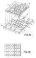
- FIG. 1Ashows a typical color LCD display, in which the liquid crystal material is trapped between an upper glass plate 1 and a lower glass plate 2.
- the upper plate 1has a common transparent electrode 3 and an array 4 of color filters surrounded by a black mask 5.
- the lower plate 2includes an array 6 of transparent pixel electrodes juxtaposed underneath the array 4 of color filters. Individual pixel electrodes are activated via thin film transistors (TFT) 7 that are controlled from a video signal on the source lines 8 and a scanning signal on the gate line 9.
- TFTthin film transistors
- the LCD displayincludes the usual polarizer layers (not shown) on the glass plates 1 and 2, such that activation of selected transparent pixel electrodes allows light to pass through the corresponding color filters and reflect to the viewer, thereby creating a color image.
- a typical LCD displaysuch as the Epson LB 2F-BC00, manufactured by Seiko-Epson Company, Japan, has about 240 lines of pixels and about 300 pixels per line, with an image aspect ratio of 4:3.
- Such an aspect ratioallows the entire area of the image obtained from the 4:3 aspect ratio NTSC format CCD sensor to be displayed on the LCD screen, so that the LCD screen composition will be the same as the image that is recorded by the camcorder NTSC format recorder, for later display on an NTSC format television display.
- the LCDhas only 240 lines of pixels, the interlaced NTSC signal is displayed using a "repeat field" technique, where both the odd and even fields from the NTSC format sensor are displayed using the same lines of pixels on the LCD.
- This LCDlike most commercially available LCDs, has "rectangular" pixels, rather than square pixels, where the distance between pixels in the horizontal direction is for example 2/3 the distance in the vertical direction.
- the LCD pixelsare overlaid with a diagonal RGB stripe pattern as shown in Figure 1B.
- camcordersIn camcorders, the processing for both the still images and the motion images is identical. Such processing is normally implemented by hardwired analog integrated circuits, although camcorders which use digital image processing integrated circuits have been produced. Such camcorders convert the signal from the CCD sensor into an NTSC composite or component format signal, which is provided to a video recording subsystem or a video output jack.
- the color LCD displayincludes circuitry to decode the NTSC composite or component signal back into spatially subsampled RGB signals to drive the individual RGB pixels on the LCD sensor.
- the electronic camerais operable in a still image mode and in a motion preview mode, said electronic camera having an image sensor including a two-dimensional array of image pixels covered by a mosaic pattern of color filters, said image sensor providing a stream of color pixel signals at an output thereof suitable for still imaging, and an analog-to-digital stage for converting the color pixel signals into digital pixel signals, characterized by a color display comprising a discrete two-dimensional arrangement of color display pixels, said color display having fewer color display pixels than the number of image pixels on the image sensor; and a preview mode processor for mapping the digital image pixel signals into at least a viewable portion of the color display pixels by combining same-colored image pixels into a fewer number of intermediate pixels, each associated with a single color, that correspond to the arrangement of the color display pixels.
- the advantage of the inventionis that the two modes can be tailored for a relatively low quality "motion" mode and a much higher quality "still” mode.
- the motion mode images from the CCD sensorare processed by a hardwired digital signal processing circuit that generates low resolution, spatially subsampled digital image data which can directly drive the relatively low resolution LCD display. This reduces the complexity and clock frequency of the required circuitry, compared to generating an NTSC format signal, as is normally done in the prior art.
- the still mode image from the CCD sensoris processed by a general purpose processor (CPU) which executes an image processing software program in order to produce a high quality digital still image.
- CPUgeneral purpose processor
- FIG. 2A block diagram of a camera incorporating dual modes of processing according to the invention is shown in Figure 2.
- the cameraincludes an electronic color display, for example, a color liquid crystal (LCD) display 10 of the type shown in Figure 1A, and a user control section 12 having a number of user control buttons, including zoom buttons 14, a preview button 15 and a capture button 16.
- a power switchnot shown
- the usercomposes the picture by depressing the "zoom in” or “zoom out” buttons 14, and by adjusting the position of the camera, while observing the display image.
- the userWhen the user is satisfied with the composition on the color LCD display 10, the user depresses the capture button 16. The camera then captures a single still image, firing a flash 18 if necessary when the ambient illumination level is low.
- the still imageis focused upon an image sensor 20 by a motor driven zoom lens 22.
- the intensity of the image light upon the sensor 20is regulated by a motor-driven, variable, mechanical aperture 24, while exposure time is regulated electronically by appropriate clocking of the sensor 20.
- the still image from the image sensor 20is processed and digitally stored on a removable memory card 26.
- a timing and control section 27which is an application specific integrated circuit (ASIC) with processing and timing functions, for both capture and preview operating modes.
- the timing and control section 27includes a sensor timing circuit 28 for controlling the image sensor functions.
- the sensor timing circuit 28provides the signals to enable sensor drivers 30, which provide horizontal clocks (H1, H2), vertical clocks (V1, V2), as well as a signal FDG for activating a drain structure on the sensor 20.
- the output of the image sensor 20is amplified and processed in an analog gain and sampling (correlated double sampling (CDS)) circuit 32, and converted to digital form in A/D converter stage 34.
- CDScorrelated double sampling
- the A/D output signalis provided to a processor section 35, which includes a digital processor 36 for temporarily storing the still images in a DRAM memory 38.
- the digital processor 36then performs image processing on the still images, and finally stores the processed images on the removable memory card 26 via a memory card interface circuit 40, which may use the PCMCIA 2.0 standard interface.
- An EPROM memory 42is used to store the firmware which operates the processor 36.
- the components of the processor 35are interconnected through a data bus 43, which also connects to the timing and control section 27 and to the card interface 40.
- the motor-driven zoom lens 22includes a zoom motor 44, a focus motor 46, and an aperture motor 48 (all controlled by lens motor drivers 50).
- the timing and control section 27further includes a control interface 52 connected to the lens motor drivers 50 and to a flash control circuit 53 via a photosystem interface block 54, which controls the operation of the zoom lens 22 and the flash 18.
- the lens zoom positionis controlled by the photosystem interface block 54 based on position input from the zoom control buttons 14 through a user status and control section 55.
- the focusing, exposure control, and white balanceis done automatically, as is typically the case in consumer camcorders. This is done by computing "image statistics" in an image statistics processor 60 in the real-time ASIC (timing and control section 27) as preview images are continuously read out of the image sensor 20.
- the computed valuesare then used by a program implemented in the digital processor 36, which decides how to adjust the focus motor, aperture, analog gain control, and analog white balance controls via the control interface 52 and the photosystems interface 54 on the ASIC timing and control section 27.
- the digital processor 36 and the control interface 52are shown as being within two separate sections, in some implementations the same component could be used to perform both of these functions (as well as other of the recited functions).
- Sensor image datais passed to the processor section 35 through a high speed interface 56 in the timing and control section 27.
- the sensor image datais also directed to the color LCD display 10 through a preview mode processing circuit 58.
- the timing and control section (ASIC) 27is operable in two modes, a relatively low quality "motion" mode and a much higher quality “still” mode.
- images from the sensor 20are processed by the preview mode processing circuit 58; in the still mode, images from the sensor 20 are processed in the processor 35.
- the processor 35is a software-driven digital processing system that is slower than the ASIC 27.
- the preview mode processing circuit 58is a hardwired digital signal processing circuit (part of the ASIC 27) that generates low resolution, spatially subsampled digital image data which can directly drive the relatively low resolution color LCD display 10. This reduces the complexity and clock frequency of the required circuitry, compared to generating an NTSC format signal, as is normally done in the prior art.
- the preview mode processing circuitincludes a pixel remapper 62 for mapping the greater number of image pixels from the sensor 20 into the lesser number of display pixels (i.e., corresponding to the array 6 of transparent pixel electrodes in Figure 1) in the color LCD display 10.
- the color saturation of the remapped pixelsis then adjusted in a color adjustment circuit 63 and its output is applied to a multiplexer 64.
- the multiplexer 64selects image data either from the preview mode processing circuit 58, producing a preview image, or from the high speed interface 56, which allows for suitably preprocessed viewing of stored images.
- the image processing used to create the preview modeis done in the timing and control ASIC 27, since the processing must be done rapidly. About 60 images per second are processed in preview mode. However, since the image quality of the displayed image is limited by the resolution and color gamut of the LCD screen of the LCD color display 10, there is no need for elaborate image processing. Therefore, simple "preview mode" image processing is performed in a fixed digital circuit embedded in the preview mode processing circuit 58 (which is part of the ASIC). The quality requirements for the still mode are much greater, since these images will be downloaded to a computer, and may be displayed on a high resolution CRT display, or printed on a high quality thermal printer. Therefore, the digital image processing must be more elaborate.
- firmware-stored softwareallows the still mode image processing to be upgraded without requiring a new ASIC design. In effect, what happens is that a relatively less complex digital image processing technique is used in the motion preview mode, but at a higher data rate, and a relatively more complex digital image processing technique is used in the still mode, but at a slower data rate.
- a system oscillator 100produces a 12 MHz clock frequency for use in the motion mode to obtain more updates/second (e.g., 60 images per second), while a divider 102 divides by two to provide a 6 MHz clock frequency for the still mode.
- the lower frequencyallows more time to accurately position the clamp and sample pulses so as to avoid CCD output signal transitions. This increases noise immunity in the still mode.
- a multiplexer 104is enabled by the control interface 52 to determine which clock frequency is applied to the sensor timing circuit 28. Though not specifically shown, the changed timing is also communicated to the A/D stage 34 and other timing and control circuits.
- the sensor 20is a progressive scan interline image sensor having a noninterlaced architecture, as shown in more detail in Figure 3A.
- the sensorcomprises a two-dimensional array of photosites 66, e.g. photodiodes, arranged in rows and columns of image pixels, a plurality of vertical registers 68 adjacent photosite columns for transferring rows of image pixel charge from the photosites 66 to a horizontal register 70 for readout responsive to clock signals from the sensor drivers 30, and a charge drain (specifically, a fast dump structure 72) interposed between the output of the vertical registers 68 and the horizontal register 70 for eliminating complete rows of image pixels at a time from the image sensor 20.
- a charge drainspecifically, a fast dump structure 72
- a preferred image sensoris the Kodak model CCD KAI-0400CM image sensor, which has approximately 512 active lines with approximately 768 active pixels per line and an image aspect ratio of 3:2. This sensor is described in a Performance Specification document available from Eastman Kodak Company, Rochester, New York. Each pixel is 9 microns "square", since both the vertical and horizontal distances between the centers of adjacent pixels are 9 microns.
- the 3:2 image aspect ratio of the CCD sensoralthough wider than the 4:3 aspect ratio of the display, is considered to be a preferred aspect ratio for still photography, in that the standard 35mm film format, and standard 4R (4" x 6") prints also have a 3:2 image aspect ratio.
- the sensoruses a color filter array pattern known as the "Bayer checkerboard" pattern, described in U.S. patent 3,971,065, which is shown in Figure 4.
- a color filter arrayis characterized by a mosaic pattern in which the filter colors alternate in both line and column directions.
- all of the image pixels on the sensorare transferred as color image pixels to the horizontal register 70, which delivers a stream of color pixel signals to the analog gain and CDS circuit 32 (see Figure 2).
- the color pixel signalsare subsequently converted to digital pixel signals in the A/D converter 34.
- the sensor 20uses a progressive scan readout method, which allows the entire image to be read out in a single scan.
- the accumulated or integrated charge for the photodiodes comprising the pixels 66is transported from the photosites to light protected vertical (parallel) registers 68 by applying a large positive voltage to the phase-one vertical clock (V1). This reads out every row, or line, into the vertical registers 68.
- the image pixel chargeis then transported from the vertical registers 68 to the horizontal register 70 by two-phase clocking of the vertical clocks (V1, V2). Between the vertical and horizontal registers is the fast dump structure 72, which is further described in the Performance Specification document for the KAI-0400CM sensor.
- fast dump gate line FDGBy setting a suitable positive potential on a fast dump gate line FDG, charge from the row of pixel values currently adjacent to the fast dump structure 72 is transferred from the CCD directly into the sensor substrate 74 rather than to the horizontal register 70. This dump, or line clear, is accomplished during the vertical-to-horizontal transfer time.
- the fast dump structure 72allows lines of charge to be eliminated.
- the timing and control section 27operates the electronic camera shown in Figure 2 in the two aforementioned modes, including a first "still” mode wherein all rows of image pixel charge corresponding to each line are progressively read out through the horizontal register 70 during a single scan, and a second "motion" mode wherein some of the rows of image pixel charge corresponding to some lines are eliminated through the fast dump structure 72 prior to readout.
- the first modecorresponds to a high quality still imaging mode while the second mode corresponds to a special "line skipping" mode for driving the color LCD display 10.
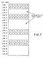
- the timing and control section 27controls the fast dump structure 72 to eliminate two or more consecutive lines of image charge from the image sensor 20 for every one or more lines of image charge that are transferred to the horizontal register 70 for readout, thereby generating a pattern of lines (shown in Figure 7) suitable for driving the LCD display in a "repeat field" mode.
- An appropriate video signalwhich displays the entire 3:2 aspect ratio sensor image on the 4:3 aspect ratio LCD, without introducing geometric distortion, is generated by alternately eliminating two or four consecutive lines of image charge for every pair of lines of image charge that are transferred to the horizontal register 70.
- the sensor timing circuit 28is controlled by the control interface 52 to provide the clock signals V1, V2, H1, H2, and the gate signal FDG according to the two modes of operation.
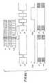
- the timing signals for the first modeare shown in Figure 5; those for the second mode are shown in Figure 6a and 6b.
- the two-phase cycling of signals V1 and V2control the transfer of lines of image pixel charge from the vertical registers 68 to the horizontal register 70.
- the two-phase cycling of signals H1 and H2control the transfer of a stream of color pixel signals from the horizontal register 70 to subsequent circuits in the camera.
- the level of the signal FDGdetermines whether the image charge is dumped to the substrate 74 or transferred to the horizontal register 70.
- the sensor 20includes the aforementioned array of color filters arranged in a particular mosaic color pattern (e.g., the checkerboard Bayer pattern of Fig. 3), and the lines of image charge that are transferred to the horizontal register 70 should preserve that particular color pattern in the pattern of lines that are generated for the line-skipping readout.
- the sensoris read out in the second mode as shown in Figure 7, using the timing shown in Figures 6A and 6B. As shown in Figure 6A, the first two lines (1 and 2) are read out as in the normal mode. These provide a green-red and a blue-green line.
- the next two lines (3 and 4)are eliminated by turning on the fast dump structure 72 during the time that these lines are transferred past the fast dump structure 72.
- lines 5 and 6are read out normally, and then lines 7, 8, 9, and 10 are eliminated.
- the Figure 6A timingis used to read out lines 11 and 12, while eliminating lines 13 and 14, and then the Figure 6B timing is used to read out lines 15 and 16, while eliminating lines 17-20. This process proceeds for the entire image readout period, during which 102 pairs of lines are read out, and 154 pairs of lines are eliminated.
- This special “line skipping” readout modeallows the sensor 3:2 aspect ratio image to be fully displayed on a 4:3 aspect ratio LCD without “geometric distortion", that is, without stretching the image vertically, and without cropping off the horizontal edges of the image from the image sensor. This allows the LCD to properly show the entire 3:2 aspect ratio image captured by the sensor, so that an image can be properly composed.
- the 512 lines of the CCD imagerare read out using the special "line skipping" mode, they are displayed using only 204 out of the approximately 240 LCD lines of pixels.
- the remaining approximately 36 linescan either be masked behind a bezel, so that they are not visible, or preferably may be used to display status information, such as the time-of-day, image number, or a "push-button menu" for the user buttons.
- Figure 11shows a useful application of such conversions.
- a sensor having a 3:2 aspect ratiois shown mapped into an image area 90 of an LCD display screen 92 having a 4:3 aspect ratio.
- a proportional remappingleaves a status area 94 available for other purposes, specifically to show text indicating the function of a set of reconfigurable control buttons 96 in the control section 12.
- the function of the buttonsis specified by the user status and control section 55 ( Figure 2).
- This status information graphics datacan be supplied by the digital processor to the LCD 10 via high speed interface 56, when the MUX 64 is controlled so as to use the digital data from interface 56, rather than from circuit 58, for supplying data to the final approximately 32 lines of the display 10.
- the “line skipping” readoutcauses some minor vertical sampling artifacts, but these are not noticeable in the small LCD displays.
- the pixels output for the sensor 20 in line skipping modecontinue to have the Bayer-type color filter repeating pattern, so that they can be processed using processing techniques designed for the Bayer pattern.
- the processing complexity of the camera of Figure 2is considerably simplified by directly mapping the RGB sensor pixels 66 to the RGB pixels of the display 10.
- the easiest way to do this for the image sensor 20(512 lines x 768 pixels and 3:2 aspect- ratio) is to have an LCD display with 512 x 768 pixels and the same aspect ratio and color filter pattern.
- LCDshave fewer display pixels than image pixels on the image sensor, normally have a 4:3 image aspect ratio, and use the diagonally striped RGB pattern shown in Figure 1B.
- an LCD pixel array of about 240 lines x 312 pixels per lineis assumed.
- the sensor pixelsare processed in a "pixel mapping circuit", such as the LCD pixel remapper 62.
- a pixel mapping circuitsuch as the LCD pixel remapper 62.
- a simple "pixel mapping" circuitmaps four green sensor pixel signals into one green LCD pixel for one line by summing two green sensor values, spaced apart by 4 CCD pixel positions, in the green pixel summer 76 and dividing by two via bit-shift wiring. The necessary delay is provided by the registers 82 clocked at one fourth the pixel rate, further delayed by one pixel clock. It also maps four red sensor pixels into one LCD pixel in the same manner (using the red/blue summer 78), and also stores this value in a 100 pixel FIFO 80.
- the FIFO 80compensates for the fact that the sensor has line sequential red and blue pixels, by supplying blue pixels on the red sensor lines, and red pixels on the blue sensor lines.
- the mapping processis basically, therefore, a process which, in its simplest form, involves averaging of signals to produce a smaller number of output color pixels than input color pixels. (The CFA interpolation algorithm discussed in reference to Figure 10, on the other hand, produces a larger number of "output" color pixels than input color pixels.) Alternate groups of 2 or 4 lines of sensor values are discarded during preview mode by using the fast dump gate shown in Figure 3A, as described in connection with the "line skipping" mode. This allows the sensor readout time to be decreased by more than 1/2 during the preview mode.
- the active matrix LCDcan be updated at a slower frequency than is normally used. This reduces the cost and power consumption of the LCD driver circuits (not shown). For example, the LCD can be updated at 30 Hz (provided the LCD active matrix display is designed so as not to exhibit noticeable flicker at this update rate), instead of 60 Hz.
- the LCD color adjust circuit 63increases the color saturation.of the image by forming R-G and B-G color difference signals, and adding or subtracting a fraction of these signals in an array 84 of adders and subtractors from the original RGB signals in order to increase the color saturation of the displayed image.
- This circuitperforms a similar function as a 3x3 color matrix, but uses less hardware and provides less color accuracy. The color accuracy is not critical for the LCD display, however, due to the limited color reproduction quality of such displays. The color reproduction of the still image is much more important, and is done with a more complicated and precise color correction method with the stored firmware in EPROM 42.
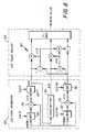
- Figures 9A and 9Bshow the processing in the image statistics processor 60, which computes real-time values for both still and motion image capture, all during the preview mode. These values include 24 R, G, and B averages used to set white balance and exposure, and 6 average high frequency "detail" values used to set focus.
- the 24 RGB averages for white balanceare calculated for a group of 4 x 6 rectangular image regions, for each of R, G, and B; a block diagram of the calculation in one color is shown in Figure 9A.
- the 6 average "detail" values for focusingare calculated for green pixels only by accumulating the absolute value of the differences between nearby green values; a block diagram of this calculation is shown in Figure 9B. These values are computed for each preview image and downloaded to the processor 36.
- the processor 36implements a firmware stored procedure which determines the optimum exposure parameters (exposure time, f/stop, and analog gain), white balance settings, and lens focus setting. For the still mode, the processor 36 also decides, based on the last preview images, whether to fire the flash, and determines the optimum exposure parameters, white balance settings, and lens focus setting for the still mode.
- FIG. 10shows a diagram of one possible still image processing method.
- the CFA interpolation diagrammay include the green interpolation method described in U.S. patent US-A-5,382,976, in the name of the same assignee as the present application, and the chrominance interpolation method described in U.S. patent 4,642,678.
- the color matrix, tone correction, and edge enhancement stepsmay be similar to those described in U.S. patent 5,189,511.
- the image compression methodmay be the JPEG standard compression technique.
- the cameracan also optionally capture "bursts" of high quality still images into the DRAM memory during the "still” mode, which are then processed as shown in Figure 10.
- the "burst” modecould utilize different exposure parameters (exposure time, aperture, analog gain, flash, and digital processing) than either the motion or the single still mode.
- Figure 3Bshows a progressive scan sensor with two readout registers 86 and 88 (which corresponds to the Performance Specification document for the Kodak KAI-031CM image sensor; the preferred embodiment of Figure 3A simply uses but one register).
- the purposeis to eliminate the FIFO line delay 80 in the LCD pixel remapper 62.
- the pairs of lines read out by the registersinclude both a green/red line and a blue/green line.
- the LCD pixel remapper 62can then be designed to map from the CCD sensor color pixel pattern to the required RGBRGB LCD pixel pattern, without using a line delay. Since two CCD lines are read out in parallel, for each LCD line, fewer lines are eliminated via the fast dump gate than for the single-register sensor shown in Figure 3A.
- the CCD readoutwould involve fast dumping one pair of lines for every four pairs of lines read out from the CCD sensor.
- the pixel readout procedure for the horizontal registerscan then be varied depending on the mode of operation: both registers are used for the motion imaging mode and one register is used for the still imaging mode.
Landscapes
- Engineering & Computer Science (AREA)
- Multimedia (AREA)
- Signal Processing (AREA)
- Human Computer Interaction (AREA)
- Physics & Mathematics (AREA)
- Spectroscopy & Molecular Physics (AREA)
- Color Television Image Signal Generators (AREA)
- Studio Devices (AREA)
- Transforming Light Signals Into Electric Signals (AREA)
Description
Claims (10)
- An electronic camera operable in a still image mode and in amotion preview mode, said electronic camera having an image sensor (20)including a two-dimensional array of image pixels (66) covered by a mosaicpattern of color filters, said image sensor providing a stream of color pixel signalsat an output thereof suitable for still imaging, and an analog-to-digital stage (34)for converting the color pixel signals into digital pixel signais,
characterized by a color display (10) comprising a discrete two-dimensionalarrangement of color display pixels (6), said color display havingfewer color display pixels than the number of image pixels on the image sensor(20); and
a preview mode processor (58) for mapping the digital image pixelsignals into at least a viewable portion of the color display pixels by combiningsame-colored image pixels into a fewer number of intermediate pixels, eachassociated with a single color, that correspond to the arrangement of the colordisplay pixels. - An electronic camera as claimed in claim 1 wherein said mosaicpattern of color filters covering the image sensor (20) is different than thearrangement of color display pixels (6).
- An electronic camera as claimed in claim 2 wherein said mosaicpattern of color filters covering the image sensor (20) is the following pattern:
R G R G G B G B R G R G G B G B - An electronic camera as claimed in claim 3 wherein the previewmode processor (58) further modifies the saturation of the averaged display pixelsby adding or subtracting portions of one or more of the other colors to eachaveraged display pixel.
- An electronic camera as claimed in claim 1 wherein the imagesensor (20) and the viewable portion of the color display (10) have the sameaspect ratios such that substantially all of the image pixel signals can be mappedinto substantially all of the color display pixels (6).
- An electronic camera as claimed in claim 1 wherein the imagesensor (20) and the color display (10) have different aspect ratios such thatsubstantially all of the image pixel signals are mapped into the viewable portion ofthe color display pixels, leaving another portion of the color display pixels availablefor non-imaging use.
- An electronic camera as claimed in claim 1 wherein said imagesensor further comprises a two-dimensional color filter array, a two- dimensionalarray of image pixels (66) arranged in rows and columns with respect to the colorfilter array, a horizontal readout section (70) for outputting rows of color pixelsignals, and a still image processor (35) for processing the digital pixel signalsobtained during the still image mode.
- An electronic camera as claimed in claims 1 or 7, wherein theclock frequency for operating the image sensor (20) in the motion preview modeis different from the clock frequency for operating the image sensor in the stillimage mode;
and wherein a timing generator (28) is provided for operating the imagesensor according to the respective different clock signal frequencies dependingupon which operating mode is being used. - An electronic camera as claimed in claim 7 wherein the horizontalreadout section comprises two horizontal readout registers (76, 78) and the pixelreadout procedure comprises use of one horizontal register for the still imagemode and the use of both horizontal registers for the motion preview mode.
- An electronic camera as claimed in claims 1, 7, 8 or 9 wherein thestill image mode includes the capture of a single image or the capture of a burst ofimages.
Applications Claiming Priority (2)
| Application Number | Priority Date | Filing Date | Title |
|---|---|---|---|
| US367399 | 1989-06-16 | ||
| US08/367,399US5828406A (en) | 1994-12-30 | 1994-12-30 | Electronic camera having a processor for mapping image pixel signals into color display pixels |
Publications (3)
| Publication Number | Publication Date |
|---|---|
| EP0720388A2 EP0720388A2 (en) | 1996-07-03 |
| EP0720388A3 EP0720388A3 (en) | 1997-05-02 |
| EP0720388B1true EP0720388B1 (en) | 2001-06-27 |
Family
ID=23447014
Family Applications (1)
| Application Number | Title | Priority Date | Filing Date |
|---|---|---|---|
| EP95120480AExpired - LifetimeEP0720388B1 (en) | 1994-12-30 | 1995-12-22 | An electronic camera having dual modes for previewing and capturing still images |
Country Status (4)
| Country | Link |
|---|---|
| US (2) | US5828406A (en) |
| EP (1) | EP0720388B1 (en) |
| JP (1) | JP3604480B2 (en) |
| DE (1) | DE69521488T2 (en) |
Families Citing this family (214)
| Publication number | Priority date | Publication date | Assignee | Title |
|---|---|---|---|---|
| JPH0823473A (en)* | 1994-07-05 | 1996-01-23 | Canon Inc | Imaging device |
| US5828406A (en)* | 1994-12-30 | 1998-10-27 | Eastman Kodak Company | Electronic camera having a processor for mapping image pixel signals into color display pixels |
| DE69718694T2 (en)* | 1996-03-06 | 2003-10-16 | Sony Corp., Tokio/Tokyo | Electronic still camera |
| US20020057349A1 (en) | 1996-03-06 | 2002-05-16 | Masanori Yamaguchi | Image pickup apparatus and solid state image pickup device |
| JP3374651B2 (en)* | 1996-03-29 | 2003-02-10 | ソニー株式会社 | Digital electronic imaging apparatus and imaging method |
| JP3832089B2 (en)* | 1997-05-26 | 2006-10-11 | セイコーエプソン株式会社 | Digital camera and printing system |
| JPH09298693A (en)* | 1996-05-08 | 1997-11-18 | Fuji Photo Film Co Ltd | Recording control method for electronic still camera |
| JPH104531A (en)* | 1996-06-14 | 1998-01-06 | Nikon Corp | Information processing device |
| GB9612567D0 (en)* | 1996-06-15 | 1996-08-21 | Kodak Ltd | Scanning of images |
| US6249316B1 (en) | 1996-08-23 | 2001-06-19 | Flashpoint Technology, Inc. | Method and system for creating a temporary group of images on a digital camera |
| US5943093A (en)* | 1996-09-26 | 1999-08-24 | Flashpoint Technology, Inc. | Software driver digital camera system with image storage tags |
| US5986701A (en)* | 1996-09-26 | 1999-11-16 | Flashpoint Technology, Inc. | Method and system of grouping related images captured with a digital image capture device |
| US6169575B1 (en) | 1996-09-26 | 2001-01-02 | Flashpoint Technology, Inc. | Method and system for controlled time-based image group formation |
| US6356322B1 (en)* | 1996-09-30 | 2002-03-12 | Fuji Photo Film Co., Ltd. | Liquid crystal display system with improved contrast and less dependence on visual angle |
| US6654059B1 (en)* | 1996-10-03 | 2003-11-25 | Dalsa Corporation | Charge coupled imaging device and method in which redundant lines can be dumped |
| US5946031A (en)* | 1996-10-22 | 1999-08-31 | Polaroid Corporation | Electronic still camera with printing capability |
| JPH10136244A (en)* | 1996-11-01 | 1998-05-22 | Olympus Optical Co Ltd | Electronic image pickup device |
| EP1531619B1 (en) | 1997-01-20 | 2008-03-26 | Matsushita Electric Industrial Co., Ltd. | Digital camera with interchangeable displays |
| JPH10224684A (en)* | 1997-02-10 | 1998-08-21 | Nikon Corp | Information processing device |
| US6356306B1 (en)* | 1997-02-28 | 2002-03-12 | Sanyo Electric Co., Ltd. | Digital camera capable of converting a progressive scan signal into an interlace scan signal |
| US6570614B1 (en)* | 1997-03-14 | 2003-05-27 | Minolta Co., Ltd. | Electronic still camera |
| JPH114367A (en) | 1997-04-16 | 1999-01-06 | Seiko Epson Corp | High-speed image selection method and digital camera with high-speed image selection function |
| JP4161384B2 (en)* | 1997-04-30 | 2008-10-08 | ソニー株式会社 | Solid-state imaging device, camera using the same, and driving method of solid-state imaging device |
| JPH118797A (en)* | 1997-06-18 | 1999-01-12 | Olympus Optical Co Ltd | Electronic image pickup device |
| US6285399B1 (en)* | 1997-07-09 | 2001-09-04 | Flashpoint, Technology, Inc. | System and method for generating timing signals in an electronic imaging device |
| US5973734A (en) | 1997-07-09 | 1999-10-26 | Flashpoint Technology, Inc. | Method and apparatus for correcting aspect ratio in a camera graphical user interface |
| JPH11103407A (en)* | 1997-09-29 | 1999-04-13 | Nec Corp | Ccd data pixel interpolating circuit and digital still camera provided with the same |
| JP3909930B2 (en)* | 1997-09-30 | 2007-04-25 | オリンパス株式会社 | Single plate color solid-state imaging device |
| US6963359B1 (en)* | 1997-10-23 | 2005-11-08 | Fuji Photo Film Co., Ltd. | Electronic still camera, instant printer and instant film |
| JPH11168745A (en)* | 1997-12-03 | 1999-06-22 | Minolta Co Ltd | Digital camera |
| JP3548410B2 (en)* | 1997-12-25 | 2004-07-28 | キヤノン株式会社 | Solid-state imaging device and signal reading method of solid-state imaging device |
| US6122006A (en)* | 1998-02-03 | 2000-09-19 | Eastman Kodak Company | Method for previewing a scene before actual capture by a motion-picture camera |
| US6356276B1 (en)* | 1998-03-18 | 2002-03-12 | Intel Corporation | Median computation-based integrated color interpolation and color space conversion methodology from 8-bit bayer pattern RGB color space to 12-bit YCrCb color space |
| US6563535B1 (en)* | 1998-05-19 | 2003-05-13 | Flashpoint Technology, Inc. | Image processing system for high performance digital imaging devices |
| US6850282B1 (en)* | 1998-06-02 | 2005-02-01 | Canon Kabushiki Kaisha | Remote control of image sensing apparatus |
| JP4019235B2 (en)* | 1998-06-05 | 2007-12-12 | 富士フイルム株式会社 | Imaging device driving method and electronic camera |
| US7253836B1 (en)* | 1998-06-30 | 2007-08-07 | Nikon Corporation | Digital camera, storage medium for image signal processing, carrier wave and electronic camera |
| JP4131052B2 (en) | 1998-07-17 | 2008-08-13 | ソニー株式会社 | Imaging device |
| US7197228B1 (en)* | 1998-08-28 | 2007-03-27 | Monroe David A | Multifunction remote control system for audio and video recording, capture, transmission and playback of full motion and still images |
| JP2000106678A (en)* | 1998-09-28 | 2000-04-11 | Victor Co Of Japan Ltd | Image pickup device |
| US6753922B1 (en)* | 1998-10-13 | 2004-06-22 | Intel Corporation | Image sensor mounted by mass reflow |
| JP3416536B2 (en)* | 1998-10-14 | 2003-06-16 | 三洋電機株式会社 | Digital camera |
| JP3893424B2 (en)* | 1998-11-06 | 2007-03-14 | 富士フイルム株式会社 | Solid-state imaging device and signal readout method |
| EP1014709A3 (en)* | 1998-12-24 | 2000-12-13 | Fuji Photo Film Co., Ltd. | Radiation image read-out method and apparatus |
| DE69942005D1 (en)* | 1998-12-28 | 2010-03-25 | Sanyo Electric Co | Imaging device and digital camera |
| US6317141B1 (en) | 1998-12-31 | 2001-11-13 | Flashpoint Technology, Inc. | Method and apparatus for editing heterogeneous media objects in a digital imaging device |
| JP3980782B2 (en)* | 1999-02-03 | 2007-09-26 | 富士フイルム株式会社 | Imaging control apparatus and imaging control method |
| US6320593B1 (en)* | 1999-04-20 | 2001-11-20 | Agilent Technologies, Inc. | Method of fast bi-cubic interpolation of image information |
| JP3663973B2 (en)* | 1999-05-06 | 2005-06-22 | 日本電気株式会社 | Image signal processing apparatus and image signal processing method |
| US6424795B1 (en) | 1999-07-05 | 2002-07-23 | Hitachi, Ltd. | Method and apparatus for recording and reproducing video data, and recording medium |
| US6992714B1 (en)* | 1999-05-31 | 2006-01-31 | Canon Kabushiki Kaisha | Image pickup apparatus having plural pixels arranged two-dimensionally, and selective addition of different pixel color signals to control spatial color arrangement |
| US20020044157A1 (en)* | 1999-10-13 | 2002-04-18 | Wolf Edward O. | Producing icons for accessing image files transferred from a digital camera |
| US6466618B1 (en)* | 1999-11-19 | 2002-10-15 | Sharp Laboratories Of America, Inc. | Resolution improvement for multiple images |
| US6784930B1 (en)* | 1999-11-29 | 2004-08-31 | Agilent Technologies, Inc. | Active pixel sensor with enhanced reset |
| US6522889B1 (en)* | 1999-12-23 | 2003-02-18 | Nokia Corporation | Method and apparatus for providing precise location information through a communications network |
| JP3991543B2 (en) | 2000-01-11 | 2007-10-17 | 株式会社日立製作所 | Imaging device |
| US20010050713A1 (en)* | 2000-01-28 | 2001-12-13 | Naoki Kubo | Device and method for generating timing signals of different kinds |
| JP2001298659A (en)* | 2000-02-08 | 2001-10-26 | Canon Inc | Imaging device, image processing system, imaging method, and storage medium |
| JP3750462B2 (en)* | 2000-02-22 | 2006-03-01 | コニカミノルタフォトイメージング株式会社 | Digital camera and recording medium |
| JP3631655B2 (en)* | 2000-03-22 | 2005-03-23 | シャープ株式会社 | Solid-state imaging device |
| JP4518616B2 (en) | 2000-04-13 | 2010-08-04 | ソニー株式会社 | Solid-state imaging device, driving method thereof, and camera system |
| JP2001346095A (en)* | 2000-06-02 | 2001-12-14 | Nec Corp | Digital still camera |
| US9622058B1 (en) | 2000-06-02 | 2017-04-11 | Timothy G. Newman | Apparatus, system, methods and network for communicating information associated with digital images |
| JP2004506388A (en)* | 2000-08-04 | 2004-02-26 | フォベオン・インコーポレーテッド | Fully electronic high-resolution digital still camera |
| JP4432233B2 (en)* | 2000-08-25 | 2010-03-17 | 株式会社ニコン | Electronic camera |
| US7978219B1 (en) | 2000-08-30 | 2011-07-12 | Kevin Reid Imes | Device, network, server, and methods for providing digital images and associated processing information |
| US8326352B1 (en) | 2000-09-06 | 2012-12-04 | Kevin Reid Imes | Device, network, server, and methods for providing service requests for wireless communication devices |
| JP4192428B2 (en)* | 2001-01-09 | 2008-12-10 | ソニー株式会社 | Solid-state imaging device and image input device |
| JP4315408B2 (en)* | 2001-03-09 | 2009-08-19 | キヤノン株式会社 | Multi-chip type image sensor device and signal reading method for multi-chip type image sensor |
| US6816197B2 (en) | 2001-03-21 | 2004-11-09 | Hewlett-Packard Development Company, L.P. | Bilateral filtering in a demosaicing process |
| JP2002320235A (en) | 2001-04-19 | 2002-10-31 | Fujitsu Ltd | A CMOS image sensor that generates a reduced image signal while suppressing a decrease in spatial resolution |
| US20020167599A1 (en)* | 2001-05-08 | 2002-11-14 | Carau Frank P. | Reusable camera |
| CA2351025A1 (en)* | 2001-06-19 | 2002-12-19 | Symagery Microsystems Inc. | Method and apparatus for controlling power consumption in an active pixel sensor array |
| US7133597B2 (en)* | 2001-07-05 | 2006-11-07 | Eastman Kodak Company | Recording audio enabling software and images on a removable storage medium |
| KR20030006734A (en)* | 2001-07-14 | 2003-01-23 | 엠텍비젼 주식회사 | Method and system for managing image data via network |
| JP4658401B2 (en)* | 2001-07-27 | 2011-03-23 | オリンパス株式会社 | Imaging device |
| US6837431B2 (en)* | 2002-04-09 | 2005-01-04 | Symbol Technologies, Inc. | Semiconductor device adapted for imaging bar code symbols |
| JP3973408B2 (en)* | 2001-11-22 | 2007-09-12 | 富士フイルム株式会社 | Digital movie camera and operation control method thereof |
| DE60130671D1 (en)* | 2001-12-24 | 2007-11-08 | St Microelectronics Srl | Method for contrast enhancement in digital color images |
| JP3988461B2 (en)* | 2001-12-28 | 2007-10-10 | 株式会社ニコン | Electronic camera |
| US6970608B1 (en)* | 2001-12-30 | 2005-11-29 | Cognex Technology And Investment Corporation | Method for obtaining high-resolution performance from a single-chip color image sensor |
| US6992707B2 (en)* | 2002-03-06 | 2006-01-31 | Hewlett-Packard Development Company, L.P. | Delayed encoding based joint video and still image pipeline with still burst mode |
| US20040201688A1 (en)* | 2002-03-18 | 2004-10-14 | Eastman Kodak Company | Accessing image files stored in a digital camera by a host computer |
| US7170557B2 (en)* | 2002-03-26 | 2007-01-30 | Eastman Kodak Company | Modular digital imaging system |
| US20030189647A1 (en)* | 2002-04-05 | 2003-10-09 | Kang Beng Hong Alex | Method of taking pictures |
| JP3947969B2 (en)* | 2002-05-15 | 2007-07-25 | ソニー株式会社 | Image processing apparatus, image processing method, recording medium, and program |
| JP2004064677A (en)* | 2002-07-31 | 2004-02-26 | Victor Co Of Japan Ltd | Digital camera |
| US7301568B2 (en) | 2002-08-07 | 2007-11-27 | Smith Craig M | Cameras, other imaging devices, and methods having non-uniform image remapping using a small data-set of distortion vectors |
| US6896428B2 (en)* | 2002-08-14 | 2005-05-24 | Printronix, Inc. | Printer read after print correlation method and apparatus |
| US6907194B2 (en) | 2002-11-12 | 2005-06-14 | Eastman Kodak Company | Camera having continuously cropping viewfinder |
| US7561793B2 (en)* | 2002-11-12 | 2009-07-14 | Eastman Kodak Company | User interface for controlling cropping in electronic camera |
| US7006764B2 (en)* | 2002-11-12 | 2006-02-28 | Eastman Kodak Company | User interface for controlling cropping in electronic camera |
| GB2398692B (en)* | 2003-02-21 | 2006-02-15 | Sony Uk Ltd | Colour correction |
| US7308158B2 (en)* | 2003-06-20 | 2007-12-11 | Eastman Kodak Company | Imaging method and system |
| US7480000B2 (en)* | 2003-06-25 | 2009-01-20 | Fujifilm Corporation | Image-taking apparatus including a vertical transfer control device |
| JP4457613B2 (en) | 2003-09-04 | 2010-04-28 | ソニー株式会社 | Solid-state imaging device |
| US7203131B2 (en)* | 2003-09-04 | 2007-04-10 | Johnson Outdoors Inc. | Pixel display method and apparatus |
| JP4416462B2 (en)* | 2003-09-19 | 2010-02-17 | パナソニック株式会社 | Autofocus method and autofocus camera |
| US20050068441A1 (en)* | 2003-09-26 | 2005-03-31 | Eastman Kodak Company | Multiple output CCD for color imaging |
| JP2005109994A (en)* | 2003-09-30 | 2005-04-21 | Matsushita Electric Ind Co Ltd | Imaging device |
| JP4338188B2 (en)* | 2003-10-21 | 2009-10-07 | キヤノン株式会社 | Image data reduction apparatus and method, program, storage medium, and imaging apparatus |
| US7468752B2 (en)* | 2003-10-23 | 2008-12-23 | Nokia Corporation | Camera output format for real time viewfinder/video image |
| TWI228924B (en)* | 2003-12-09 | 2005-03-01 | Sunplus Technology Co Ltd | Electric device adapted to capture and show images and pocket electric device |
| US20050134726A1 (en)* | 2003-12-18 | 2005-06-23 | Parulski Kenneth A. | Modular print scanner and digital imaging system |
| KR20050090793A (en)* | 2004-03-10 | 2005-09-14 | 삼성전자주식회사 | A unified multi-function switch apparatus of digital camcorder |
| US8659619B2 (en) | 2004-03-26 | 2014-02-25 | Intellectual Ventures Fund 83 Llc | Display device and method for determining an area of importance in an original image |
| US7529423B2 (en)* | 2004-03-26 | 2009-05-05 | Intel Corporation | SIMD four-pixel average instruction for imaging and video applications |
| US7796169B2 (en)* | 2004-04-20 | 2010-09-14 | Canon Kabushiki Kaisha | Image processing apparatus for correcting captured image |
| JP4039386B2 (en)* | 2004-04-21 | 2008-01-30 | コニカミノルタオプト株式会社 | Imaging sensor and imaging apparatus |
| US7385638B2 (en)* | 2004-04-28 | 2008-06-10 | Eastman Kodak Company | Image sensor for still or video photography |
| US20050254714A1 (en)* | 2004-05-13 | 2005-11-17 | Ramakrishna Anne | Systems and methods for data transfer with camera-enabled devices |
| US20050280726A1 (en)* | 2004-06-18 | 2005-12-22 | Eastman Kodak Company | Image sensor for still or video photography |
| US20060044441A1 (en)* | 2004-08-27 | 2006-03-02 | Eastman Kodak Company | Image sensor for still or video photography |
| TWI246322B (en)* | 2004-09-20 | 2005-12-21 | Alpha Imaging Technology Corp | Image processing device |
| US20060082670A1 (en)* | 2004-10-14 | 2006-04-20 | Eastman Kodak Company | Interline CCD for still and video photography with extended dynamic range |
| JP2006148861A (en)* | 2004-10-21 | 2006-06-08 | Matsushita Electric Ind Co Ltd | Imaging signal processing apparatus and method |
| US7379107B2 (en)* | 2004-12-10 | 2008-05-27 | Eastman Kodak Company | Image sensor for still or video photography |
| KR100543902B1 (en)* | 2005-03-28 | 2006-01-20 | 주식회사 넥서스칩스 | 3D graphic processing system and method for utilizing camera preview image |
| US7636119B2 (en) | 2005-12-21 | 2009-12-22 | Eastman Kodak Company | Image sensor for still or video photography |
| US7796174B1 (en) | 2006-04-25 | 2010-09-14 | Ball Aerospace & Technologies Corp. | Hybrid imager |
| US9224145B1 (en) | 2006-08-30 | 2015-12-29 | Qurio Holdings, Inc. | Venue based digital rights using capture device with digital watermarking capability |
| US8019167B2 (en)* | 2007-01-03 | 2011-09-13 | Human Monitoring Ltd. | Compressing high resolution images in a low resolution video |
| JP4983423B2 (en)* | 2007-06-15 | 2012-07-25 | ソニー株式会社 | Image signal processing apparatus and image signal processing method |
| JP4618280B2 (en)* | 2007-08-20 | 2011-01-26 | 富士フイルム株式会社 | Electronic camera |
| TWI338241B (en)* | 2007-08-23 | 2011-03-01 | Pixart Imaging Inc | Interactive image system, interactive device and operative method thereof |
| JP5148989B2 (en) | 2007-12-27 | 2013-02-20 | イーストマン コダック カンパニー | Imaging device |
| EP2241113A1 (en)* | 2008-01-09 | 2010-10-20 | Robert Bosch GmbH | Method and apparatus for processing colour values provided by a camera sensor |
| JP2008289172A (en)* | 2008-06-13 | 2008-11-27 | Fujifilm Corp | Solid-state electronic imaging device and control method thereof |
| US8432461B2 (en)* | 2008-12-18 | 2013-04-30 | Apple Inc. | Wireless camera with automatic wake-up and transfer capability and transfer status display |
| US8730351B2 (en) | 2008-12-18 | 2014-05-20 | Intellectual Ventures Fund 83 Llc | Method for deleting data files in an electronic device |
| KR20100133807A (en)* | 2009-06-12 | 2010-12-22 | 삼성전자주식회사 | Resolution Conversion Method for Preview Mode and Image Sensor Using the Same |
| US20110205397A1 (en) | 2010-02-24 | 2011-08-25 | John Christopher Hahn | Portable imaging device having display with improved visibility under adverse conditions |
| US8957981B2 (en) | 2010-03-03 | 2015-02-17 | Intellectual Ventures Fund 83 Llc | Imaging device for capturing self-portrait images |
| US20110228075A1 (en) | 2010-03-22 | 2011-09-22 | Madden Thomas E | Digital camera with underwater capture mode |
| US20110228074A1 (en)* | 2010-03-22 | 2011-09-22 | Parulski Kenneth A | Underwater camera with presssure sensor |
| US8665340B2 (en) | 2010-04-29 | 2014-03-04 | Intellectual Ventures Fund 83 Llc | Indoor/outdoor scene detection using GPS |
| US8520088B2 (en) | 2010-05-25 | 2013-08-27 | Intellectual Ventures Fund 83 Llc | Storing a video summary as metadata |
| US8446490B2 (en) | 2010-05-25 | 2013-05-21 | Intellectual Ventures Fund 83 Llc | Video capture system producing a video summary |
| US8605221B2 (en) | 2010-05-25 | 2013-12-10 | Intellectual Ventures Fund 83 Llc | Determining key video snippets using selection criteria to form a video summary |
| US8599316B2 (en) | 2010-05-25 | 2013-12-03 | Intellectual Ventures Fund 83 Llc | Method for determining key video frames |
| US8432965B2 (en) | 2010-05-25 | 2013-04-30 | Intellectual Ventures Fund 83 Llc | Efficient method for assembling key video snippets to form a video summary |
| US8619150B2 (en) | 2010-05-25 | 2013-12-31 | Intellectual Ventures Fund 83 Llc | Ranking key video frames using camera fixation |
| US8432456B2 (en) | 2010-06-18 | 2013-04-30 | Apple Inc. | Digital camera for sharing digital images |
| KR101198249B1 (en) | 2010-07-07 | 2012-11-07 | 에스케이하이닉스 주식회사 | Column circuit and pixel binning circuit of image sensor |
| US20120019704A1 (en) | 2010-07-26 | 2012-01-26 | Levey Charles I | Automatic digital camera photography mode selection |
| US8970720B2 (en) | 2010-07-26 | 2015-03-03 | Apple Inc. | Automatic digital camera photography mode selection |
| US20120050570A1 (en) | 2010-08-26 | 2012-03-01 | Jasinski David W | Audio processing based on scene type |
| HRP20220077T1 (en) | 2010-09-13 | 2022-04-15 | Contour Ip Holding, Llc | Portable digital video camera configured for remote image acquisition control and viewing |
| US8494301B2 (en) | 2010-09-16 | 2013-07-23 | Eastman Kodak Company | Refocusing images using scene captured images |
| US8836714B2 (en)* | 2010-10-29 | 2014-09-16 | The University Of Utah Research Foundation | Rapid, interactive editing of massive imagery data |
| US20120113515A1 (en) | 2010-11-10 | 2012-05-10 | Karn Keith S | Imaging system with automatically engaging image stabilization |
| US8643734B2 (en) | 2010-11-10 | 2014-02-04 | Apple Inc. | Automatic engagement of image stabilization |
| US8606444B2 (en) | 2010-12-29 | 2013-12-10 | Caterpillar Inc. | Machine and power system with electrical energy storage device |
| US8853883B2 (en) | 2010-12-29 | 2014-10-07 | Caterpillar Inc. | System and methods for starting a prime mover of a power system |
| US9013602B2 (en) | 2011-01-03 | 2015-04-21 | Intellectual Ventures Fund 83 Llc | Digital camera system having a retail mode |
| US8224176B1 (en) | 2011-01-10 | 2012-07-17 | Eastman Kodak Company | Combined ambient and flash exposure for improved image quality |
| JP5820120B2 (en)* | 2011-01-28 | 2015-11-24 | キヤノン株式会社 | Imaging apparatus and control method thereof |
| US8428308B2 (en) | 2011-02-04 | 2013-04-23 | Apple Inc. | Estimating subject motion for capture setting determination |
| US8379934B2 (en) | 2011-02-04 | 2013-02-19 | Eastman Kodak Company | Estimating subject motion between image frames |
| US20120236173A1 (en) | 2011-03-17 | 2012-09-20 | Telek Michael J | Digital camera user interface which adapts to environmental conditions |
| US8736697B2 (en) | 2011-03-25 | 2014-05-27 | Apple Inc. | Digital camera having burst image capture mode |
| US20120243802A1 (en) | 2011-03-25 | 2012-09-27 | William Vernon Fintel | Composite image formed from an image sequence |
| US8736704B2 (en) | 2011-03-25 | 2014-05-27 | Apple Inc. | Digital camera for capturing an image sequence |
| US20120249853A1 (en) | 2011-03-28 | 2012-10-04 | Marc Krolczyk | Digital camera for reviewing related images |
| US8736716B2 (en) | 2011-04-06 | 2014-05-27 | Apple Inc. | Digital camera having variable duration burst mode |
| US9241101B2 (en) | 2011-05-04 | 2016-01-19 | Intellectual Ventures Fund 83 Llc | Digital camera user interface for text entry |
| US9848158B2 (en) | 2011-05-04 | 2017-12-19 | Monument Peak Ventures, Llc | Digital camera user interface for video trimming |
| US8780180B2 (en) | 2011-05-13 | 2014-07-15 | Apple Inc. | Stereoscopic camera using anaglyphic display during capture |
| US8643746B2 (en) | 2011-05-18 | 2014-02-04 | Intellectual Ventures Fund 83 Llc | Video summary including a particular person |
| US8665345B2 (en) | 2011-05-18 | 2014-03-04 | Intellectual Ventures Fund 83 Llc | Video summary including a feature of interest |
| US9117483B2 (en) | 2011-06-03 | 2015-08-25 | Michael Edward Zaletel | Method and apparatus for dynamically recording, editing and combining multiple live video clips and still photographs into a finished composition |
| CN102843525B (en)* | 2011-06-23 | 2015-05-27 | 中国科学院西安光学精密机械研究所 | FPGA-based CCD control circuit realization method and circuit thereof |
| US8760527B2 (en) | 2011-06-24 | 2014-06-24 | Apple Inc. | Extending a digital camera focus range |
| US8754953B2 (en) | 2011-06-24 | 2014-06-17 | Apple Inc. | Digital camera providing an extended focus range |
| WO2012177495A1 (en) | 2011-06-24 | 2012-12-27 | Eastman Kodak Company | Digital camera providing an extended focus range |
| US9055276B2 (en) | 2011-07-29 | 2015-06-09 | Apple Inc. | Camera having processing customized for identified persons |
| US20130064531A1 (en) | 2011-09-13 | 2013-03-14 | Bruce Harold Pillman | Zoom flash with no moving parts |
| US8593564B2 (en) | 2011-09-22 | 2013-11-26 | Apple Inc. | Digital camera including refocusable imaging mode adaptor |
| WO2013043488A1 (en) | 2011-09-22 | 2013-03-28 | Eastman Kodak Company | Digital imaging system with refocusable imaging mode |
| US9521315B2 (en)* | 2011-11-01 | 2016-12-13 | Nokia Technologies Oy | Apparatus and method for forming new images by determining stylistic settings of existing images |
| US9253340B2 (en) | 2011-11-11 | 2016-02-02 | Intellectual Ventures Fund 83 Llc | Wireless camera with image sharing prioritization |
| US20130177242A1 (en) | 2012-01-10 | 2013-07-11 | James E. Adams, Jr. | Super-resolution image using selected edge pixels |
| US8988578B2 (en) | 2012-02-03 | 2015-03-24 | Honeywell International Inc. | Mobile computing device with improved image preview functionality |
| US8866943B2 (en) | 2012-03-09 | 2014-10-21 | Apple Inc. | Video camera providing a composite video sequence |
| US20130235234A1 (en) | 2012-03-12 | 2013-09-12 | Megan Lyn Cucci | Digital camera having multiple image capture systems |
| US8934045B2 (en) | 2012-03-12 | 2015-01-13 | Apple Inc. | Digital camera system having remote control |
| KR101889932B1 (en)* | 2012-07-25 | 2018-09-28 | 삼성전자주식회사 | Apparatus and Method for photographing image |
| US8928772B2 (en) | 2012-09-21 | 2015-01-06 | Eastman Kodak Company | Controlling the sharpness of a digital image |
| US8724919B2 (en) | 2012-09-21 | 2014-05-13 | Eastman Kodak Company | Adjusting the sharpness of a digital image |
| US9549161B2 (en)* | 2013-07-08 | 2017-01-17 | Samsung Display Co., Ltd. | Image and video in mosaic formats |
| KR102023501B1 (en) | 2013-10-02 | 2019-09-20 | 삼성전자주식회사 | System on chip including configurable image processing pipeline, and system including the same |
| EP2940989B1 (en)* | 2014-05-02 | 2022-01-05 | Samsung Electronics Co., Ltd. | Method and apparatus for generating composite image in electronic device |
| US9544497B2 (en)* | 2014-05-21 | 2017-01-10 | Qualcomm Incorporated | System and method for determining image resolution |
| GB2544946B (en) | 2014-08-31 | 2021-03-10 | Berestka John | Systems and methods for analyzing the eye |
| CN106152876B (en)* | 2015-04-15 | 2018-06-19 | 信泰光学(深圳)有限公司 | Ballistic prediction system |
| DE102015008217A1 (en)* | 2015-06-29 | 2016-12-29 | Precitec Optronik Gmbh | Method and device for determining the position and position of an eye |
| US10102789B2 (en) | 2015-10-30 | 2018-10-16 | Essential Products, Inc. | Mobile device with display overlaid with at least a light sensor |
| US9864400B2 (en) | 2015-10-30 | 2018-01-09 | Essential Products, Inc. | Camera integrated into a display |
| US9767728B2 (en) | 2015-10-30 | 2017-09-19 | Essential Products, Inc. | Light sensor beneath a dual-mode display |
| US9870024B2 (en) | 2015-10-30 | 2018-01-16 | Essential Products, Inc. | Camera integrated into a display |
| US10331260B2 (en) | 2015-10-30 | 2019-06-25 | Essential Products, Inc. | Variable transparency layers for electronic devices |
| US9823694B2 (en)* | 2015-10-30 | 2017-11-21 | Essential Products, Inc. | Camera integrated into a display |
| US9754526B2 (en) | 2015-10-30 | 2017-09-05 | Essential Products, Inc. | Mobile device with display overlaid with at least a light sensor |
| US9995990B2 (en) | 2015-12-15 | 2018-06-12 | Gopro, Inc. | Removable camera lens cover |
| WO2017147614A1 (en) | 2016-02-26 | 2017-08-31 | Essential Products, Inc. | Image capture with a camera integrated display |
| US10681266B2 (en)* | 2018-06-12 | 2020-06-09 | Carl Zeiss Ag | Method, apparatus, and system for processing digital images |
| US11431941B2 (en) | 2018-06-12 | 2022-08-30 | Carl Zeiss Ag | Method, apparatus, and system for processing digital images |
| US11425286B2 (en) | 2020-03-31 | 2022-08-23 | Gopro, Inc. | Housing assembly for image capture devices |
| US11630376B2 (en) | 2020-06-18 | 2023-04-18 | Gopro, Inc. | Removable lens accessories for image capture devices |
| WO2022019879A1 (en)* | 2020-07-20 | 2022-01-27 | Gopro, Inc. | Wide angle adapter lens for enhanced video stabilization |
| USD974450S1 (en) | 2020-08-28 | 2023-01-03 | Gopro, Inc. | Camera lens attachment |
| USD967890S1 (en) | 2020-08-28 | 2022-10-25 | Gopro, Inc. | Camera lens attachment |
| US11528417B2 (en) | 2020-08-31 | 2022-12-13 | Gopro, Inc. | Calibrating an image capture device with a detachable lens |
| US11600023B2 (en) | 2020-08-31 | 2023-03-07 | Gopro, Inc. | Optical center calibration |
Family Cites Families (18)
| Publication number | Priority date | Publication date | Assignee | Title |
|---|---|---|---|---|
| US4541010A (en)* | 1983-06-17 | 1985-09-10 | Polaroid Corporation | Electronic imaging camera |
| US4928137A (en)* | 1983-12-24 | 1990-05-22 | Canon Kabushiki Kaisha | Image sensing apparatus having a low-resolution monitor means for reducing the amount of information in an image signal, and switching means for reducing power consumption in various operating modes |
| US4691253A (en)* | 1985-05-13 | 1987-09-01 | Polaroid Corporation | Electronic imaging camera for recording either moving or still images |
| US4714963A (en)* | 1986-07-03 | 1987-12-22 | Eastman Kodak Company | Asynchronous still timing for a video camera producing movie or still images |
| US4819059A (en)* | 1987-11-13 | 1989-04-04 | Polaroid Corporation | System and method for formatting a composite still and moving image defining electronic information signal |
| US4876590A (en)* | 1988-06-17 | 1989-10-24 | Eastman Kodak Company | Low resolution verifier for a still video image |
| JPH0334686A (en)* | 1989-06-30 | 1991-02-14 | Hitachi Ltd | Digital still picture signal recording and reproducing device |
| US5226114A (en)* | 1989-10-13 | 1993-07-06 | Massachusetts Institute Of Technology | Television pictures |
| JPH044675A (en)* | 1990-04-23 | 1992-01-09 | Canon Inc | electronic camera |
| JPH0528727A (en)* | 1991-07-25 | 1993-02-05 | Canon Inc | Magnetic recording device |
| US5138454A (en)* | 1991-09-16 | 1992-08-11 | Eastman Kodak Company | Megapixel video previewer framestore and display |
| US5452017A (en)* | 1992-12-31 | 1995-09-19 | Hickman; Charles B. | Method and apparatus for electronic image color modification using hue and saturation levels |
| JP3438205B2 (en)* | 1993-02-25 | 2003-08-18 | 株式会社リコー | Digital electronic camera device |
| US5493335A (en)* | 1993-06-30 | 1996-02-20 | Eastman Kodak Company | Single sensor color camera with user selectable image record size |
| US5418565A (en)* | 1994-02-15 | 1995-05-23 | Eastman Kodak Company | CFA compatible resolution reduction in a single sensor electronic camera |
| US5440343A (en)* | 1994-02-28 | 1995-08-08 | Eastman Kodak Company | Motion/still electronic image sensing apparatus |
| US5828406A (en)* | 1994-12-30 | 1998-10-27 | Eastman Kodak Company | Electronic camera having a processor for mapping image pixel signals into color display pixels |
| US5943335A (en)* | 1996-06-28 | 1999-08-24 | Siemens Information And Communication Networks, Inc. | Method for minimizing call setups in ISDN PBX systems |
- 1994
- 1994-12-30USUS08/367,399patent/US5828406A/ennot_activeExpired - Lifetime
- 1995
- 1995-12-20JPJP33155995Apatent/JP3604480B2/ennot_activeExpired - Lifetime
- 1995-12-22EPEP95120480Apatent/EP0720388B1/ennot_activeExpired - Lifetime
- 1995-12-22DEDE69521488Tpatent/DE69521488T2/ennot_activeExpired - Lifetime
- 1997
- 1997-07-16USUS08/895,094patent/US6292218B1/ennot_activeExpired - Lifetime
Also Published As
| Publication number | Publication date |
|---|---|
| JP3604480B2 (en) | 2004-12-22 |
| DE69521488T2 (en) | 2002-04-25 |
| DE69521488D1 (en) | 2001-08-02 |
| EP0720388A2 (en) | 1996-07-03 |
| JPH08242400A (en) | 1996-09-17 |
| EP0720388A3 (en) | 1997-05-02 |
| US5828406A (en) | 1998-10-27 |
| US6292218B1 (en) | 2001-09-18 |
Similar Documents
| Publication | Publication Date | Title |
|---|---|---|
| EP0720388B1 (en) | An electronic camera having dual modes for previewing and capturing still images | |
| US4876590A (en) | Low resolution verifier for a still video image | |
| US7292267B2 (en) | Dual mode digital imaging and camera system | |
| JPH09247689A (en) | Color image pickup device | |
| US7626619B2 (en) | Digital camera | |
| JPH08172635A (en) | Image pickup device | |
| US7589778B2 (en) | Digital camera | |
| JP2000244823A (en) | Device for concealing defective pixel of imaging device | |
| KR100462260B1 (en) | Video pickup device | |
| US20010024234A1 (en) | Digital camera | |
| JP3546853B2 (en) | Imaging device and image reproduction system | |
| JP2000224604A (en) | Image processor | |
| US7609306B2 (en) | Solid-state image pickup apparatus with high- and low-sensitivity photosensitive cells, and an image shooting method using the same | |
| EP0720387A2 (en) | Method and apparatus for providing interlaced images from a progressive scan sensor in an electronic camera | |
| JP2001078210A (en) | Solid-state image pickup device and signal read method | |
| JP2003101815A (en) | Signal processor and method for processing signal | |
| JP2000023016A (en) | Digital camera | |
| JP3399454B2 (en) | Digital camera, image processing method, and recording medium recording image photographing program | |
| JP3397397B2 (en) | Imaging device | |
| JP2000175206A (en) | Imaging device | |
| JP4227203B2 (en) | Imaging device | |
| JP2713295B2 (en) | Driving method of solid-state imaging device and imaging device | |
| JP2001078208A (en) | Solid-state image pickup device and signal read method | |
| JP3999417B2 (en) | Solid-state imaging device and signal readout method | |
| JP3658049B2 (en) | Video input device |
Legal Events
| Date | Code | Title | Description |
|---|---|---|---|
| PUAI | Public reference made under article 153(3) epc to a published international application that has entered the european phase | Free format text:ORIGINAL CODE: 0009012 | |
| AK | Designated contracting states | Kind code of ref document:A2 Designated state(s):DE FR GB | |
| PUAL | Search report despatched | Free format text:ORIGINAL CODE: 0009013 | |
| AK | Designated contracting states | Kind code of ref document:A3 Designated state(s):DE FR GB | |
| 17P | Request for examination filed | Effective date:19971013 | |
| 17Q | First examination report despatched | Effective date:19990527 | |
| GRAG | Despatch of communication of intention to grant | Free format text:ORIGINAL CODE: EPIDOS AGRA | |
| GRAG | Despatch of communication of intention to grant | Free format text:ORIGINAL CODE: EPIDOS AGRA | |
| GRAH | Despatch of communication of intention to grant a patent | Free format text:ORIGINAL CODE: EPIDOS IGRA | |
| GRAH | Despatch of communication of intention to grant a patent | Free format text:ORIGINAL CODE: EPIDOS IGRA | |
| GRAA | (expected) grant | Free format text:ORIGINAL CODE: 0009210 | |
| AK | Designated contracting states | Kind code of ref document:B1 Designated state(s):DE FR GB | |
| RIN1 | Information on inventor provided before grant (corrected) | Inventor name:TREDWELL, TIMOTHY J., C/O EASTMAN KODAK CO. Inventor name:PARULSKI, KENNETH A., C/O EASTMAN KODAK CO. | |
| REF | Corresponds to: | Ref document number:69521488 Country of ref document:DE Date of ref document:20010802 | |
| ET | Fr: translation filed | ||
| REG | Reference to a national code | Ref country code:GB Ref legal event code:IF02 | |
| PLBE | No opposition filed within time limit | Free format text:ORIGINAL CODE: 0009261 | |
| STAA | Information on the status of an ep patent application or granted ep patent | Free format text:STATUS: NO OPPOSITION FILED WITHIN TIME LIMIT | |
| 26N | No opposition filed | ||
| REG | Reference to a national code | Ref country code:FR Ref legal event code:TP Owner name:APPLE INC., US Effective date:20130515 | |
| REG | Reference to a national code | Ref country code:GB Ref legal event code:732E Free format text:REGISTERED BETWEEN 20130523 AND 20130529 | |
| REG | Reference to a national code | Ref country code:DE Ref legal event code:R082 Ref document number:69521488 Country of ref document:DE Representative=s name:BARDEHLE PAGENBERG PARTNERSCHAFT PATENTANWAELT, DE | |
| REG | Reference to a national code | Ref country code:DE Ref legal event code:R082 Ref document number:69521488 Country of ref document:DE Representative=s name:BARDEHLE PAGENBERG PARTNERSCHAFT MBB PATENTANW, DE Effective date:20140113 Ref country code:DE Ref legal event code:R081 Ref document number:69521488 Country of ref document:DE Owner name:APPLE INC., CUPERTINO, US Free format text:FORMER OWNER: EASTMAN KODAK CO., ROCHESTER, N.Y., US Effective date:20140113 Ref country code:DE Ref legal event code:R081 Ref document number:69521488 Country of ref document:DE Owner name:APPLE INC., US Free format text:FORMER OWNER: EASTMAN KODAK CO., ROCHESTER, US Effective date:20140113 | |
| PGFP | Annual fee paid to national office [announced via postgrant information from national office to epo] | Ref country code:GB Payment date:20141217 Year of fee payment:20 Ref country code:DE Payment date:20141216 Year of fee payment:20 | |
| PGFP | Annual fee paid to national office [announced via postgrant information from national office to epo] | Ref country code:FR Payment date:20141208 Year of fee payment:20 | |
| REG | Reference to a national code | Ref country code:DE Ref legal event code:R071 Ref document number:69521488 Country of ref document:DE | |
| REG | Reference to a national code | Ref country code:GB Ref legal event code:PE20 Expiry date:20151221 | |
| PG25 | Lapsed in a contracting state [announced via postgrant information from national office to epo] | Ref country code:GB Free format text:LAPSE BECAUSE OF EXPIRATION OF PROTECTION Effective date:20151221 |