EP0718641B1 - Drilling system with downhole apparatus for transforming multiple downhole sensor measurements into parameters of interest and for causing the drilling direction to change in response thereto - Google Patents
Drilling system with downhole apparatus for transforming multiple downhole sensor measurements into parameters of interest and for causing the drilling direction to change in response theretoDownload PDFInfo
- Publication number
- EP0718641B1 EP0718641B1EP95119573AEP95119573AEP0718641B1EP 0718641 B1EP0718641 B1EP 0718641B1EP 95119573 AEP95119573 AEP 95119573AEP 95119573 AEP95119573 AEP 95119573AEP 0718641 B1EP0718641 B1EP 0718641B1
- Authority
- EP
- European Patent Office
- Prior art keywords
- downhole
- borehole
- drilling
- formation
- downhole assembly
- Prior art date
- Legal status (The legal status is an assumption and is not a legal conclusion. Google has not performed a legal analysis and makes no representation as to the accuracy of the status listed.)
- Expired - Lifetime
Links
- 238000005553drillingMethods0.000titleclaimsdescription222
- 238000005259measurementMethods0.000titleclaimsdescription103
- 230000004044responseEffects0.000titleclaimsdescription91
- 230000008859changeEffects0.000titleclaimsdescription9
- 230000001131transforming effectEffects0.000titledescription3
- 230000015572biosynthetic processEffects0.000claimsdescription213
- 238000005755formation reactionMethods0.000claimsdescription213
- 239000011159matrix materialSubstances0.000claimsdescription46
- 238000000034methodMethods0.000claimsdescription40
- 238000011156evaluationMethods0.000claimsdescription39
- 230000006870functionEffects0.000claimsdescription30
- XLYOFNOQVPJJNP-UHFFFAOYSA-NwaterSubstancesOXLYOFNOQVPJJNP-UHFFFAOYSA-N0.000claimsdescription24
- 239000003381stabilizerSubstances0.000claimsdescription17
- 229930195733hydrocarbonNatural products0.000claimsdescription13
- 150000002430hydrocarbonsChemical class0.000claimsdescription13
- 238000011084recoveryMethods0.000claimsdescription7
- 239000007788liquidSubstances0.000claimsdescription5
- 239000000706filtrateSubstances0.000claimsdescription3
- 230000005251gamma rayEffects0.000description48
- 230000005540biological transmissionEffects0.000description43
- 238000003860storageMethods0.000description32
- 101100041681Takifugu rubripes sand geneProteins0.000description31
- 239000004576sandSubstances0.000description31
- 238000004891communicationMethods0.000description27
- 238000012545processingMethods0.000description25
- 239000012530fluidSubstances0.000description23
- 230000008901benefitEffects0.000description19
- 239000011435rockSubstances0.000description16
- 230000000694effectsEffects0.000description15
- 230000005855radiationEffects0.000description14
- 230000000875corresponding effectEffects0.000description12
- 238000010586diagramMethods0.000description11
- TZCXTZWJZNENPQ-UHFFFAOYSA-Lbarium sulfateChemical compound[Ba+2].[O-]S([O-])(=O)=OTZCXTZWJZNENPQ-UHFFFAOYSA-L0.000description9
- 230000002596correlated effectEffects0.000description9
- 230000007613environmental effectEffects0.000description9
- 239000004020conductorSubstances0.000description8
- 239000007789gasSubstances0.000description8
- 229910052601baryteInorganic materials0.000description7
- 239000010428baryteSubstances0.000description7
- 239000000470constituentSubstances0.000description7
- 238000012937correctionMethods0.000description7
- 239000004215Carbon black (E152)Substances0.000description6
- 230000009471actionEffects0.000description6
- 238000007726management methodMethods0.000description6
- 238000001228spectrumMethods0.000description6
- 230000000155isotopic effectEffects0.000description5
- 230000035699permeabilityEffects0.000description5
- 230000008569processEffects0.000description5
- 230000003595spectral effectEffects0.000description5
- 238000012360testing methodMethods0.000description5
- 230000001276controlling effectEffects0.000description4
- 230000010363phase shiftEffects0.000description4
- XQCFHQBGMWUEMY-ZPUQHVIOSA-NNitrovinChemical compoundC=1C=C([N+]([O-])=O)OC=1\C=C\C(=NNC(=N)N)\C=C\C1=CC=C([N+]([O-])=O)O1XQCFHQBGMWUEMY-ZPUQHVIOSA-N0.000description3
- 238000001739density measurementMethods0.000description3
- 239000000835fiberSubstances0.000description3
- 238000004519manufacturing processMethods0.000description3
- 230000000149penetrating effectEffects0.000description3
- 230000000246remedial effectEffects0.000description3
- UFHFLCQGNIYNRP-UHFFFAOYSA-NHydrogenChemical compound[H][H]UFHFLCQGNIYNRP-UHFFFAOYSA-N0.000description2
- 235000015076Shorea robustaNutrition0.000description2
- 244000166071Shorea robustaSpecies0.000description2
- FAPWRFPIFSIZLT-UHFFFAOYSA-MSodium chlorideChemical compound[Na+].[Cl-]FAPWRFPIFSIZLT-UHFFFAOYSA-M0.000description2
- 230000001133accelerationEffects0.000description2
- 230000002411adverseEffects0.000description2
- 239000002131composite materialSubstances0.000description2
- 230000007423decreaseEffects0.000description2
- 238000011161developmentMethods0.000description2
- 238000005516engineering processMethods0.000description2
- 230000036541healthEffects0.000description2
- 239000001257hydrogenSubstances0.000description2
- 229910052739hydrogenInorganic materials0.000description2
- 239000011148porous materialSubstances0.000description2
- 238000003672processing methodMethods0.000description2
- 239000000047productSubstances0.000description2
- 150000003839saltsChemical class0.000description2
- 229920006395saturated elastomerPolymers0.000description2
- 239000011780sodium chlorideSubstances0.000description2
- 239000007787solidSubstances0.000description2
- 239000000126substanceSubstances0.000description2
- 238000012546transferMethods0.000description2
- 230000009466transformationEffects0.000description2
- 241000282327Felis silvestrisSpecies0.000description1
- 235000019738LimestoneNutrition0.000description1
- 239000006096absorbing agentSubstances0.000description1
- 238000004458analytical methodMethods0.000description1
- 238000003491arrayMethods0.000description1
- 238000013528artificial neural networkMethods0.000description1
- 238000009412basement excavationMethods0.000description1
- 238000005452bendingMethods0.000description1
- 229910052790berylliumInorganic materials0.000description1
- 238000004364calculation methodMethods0.000description1
- 230000015556catabolic processEffects0.000description1
- 239000004568cementSubstances0.000description1
- TVFDJXOCXUVLDH-RNFDNDRNSA-Ncesium-137Chemical compound[137Cs]TVFDJXOCXUVLDH-RNFDNDRNSA-N0.000description1
- 238000012512characterization methodMethods0.000description1
- 238000006243chemical reactionMethods0.000description1
- 239000003795chemical substances by applicationSubstances0.000description1
- 238000010276constructionMethods0.000description1
- 238000007405data analysisMethods0.000description1
- 238000013523data managementMethods0.000description1
- 238000006731degradation reactionMethods0.000description1
- 230000001934delayEffects0.000description1
- 238000007598dipping methodMethods0.000description1
- 238000006073displacement reactionMethods0.000description1
- 230000005670electromagnetic radiationEffects0.000description1
- 238000013213extrapolationMethods0.000description1
- 230000004992fissionEffects0.000description1
- 230000004907fluxEffects0.000description1
- 125000004435hydrogen atomChemical group[H]*0.000description1
- 230000003993interactionEffects0.000description1
- 230000009545invasionEffects0.000description1
- 230000033001locomotionEffects0.000description1
- 238000005461lubricationMethods0.000description1
- 238000013507mappingMethods0.000description1
- 238000013178mathematical modelMethods0.000description1
- 238000012544monitoring processMethods0.000description1
- -1oil and gasChemical class0.000description1
- 238000005457optimizationMethods0.000description1
- 230000035515penetrationEffects0.000description1
- 230000001012protectorEffects0.000description1
- 230000010349pulsationEffects0.000description1
- 238000005316response functionMethods0.000description1
- 230000035945sensitivityEffects0.000description1
- 230000005476size effectEffects0.000description1
- 230000002277temperature effectEffects0.000description1
- 230000001960triggered effectEffects0.000description1
Images


Classifications
- E—FIXED CONSTRUCTIONS
- E21—EARTH OR ROCK DRILLING; MINING
- E21B—EARTH OR ROCK DRILLING; OBTAINING OIL, GAS, WATER, SOLUBLE OR MELTABLE MATERIALS OR A SLURRY OF MINERALS FROM WELLS
- E21B7/00—Special methods or apparatus for drilling
- E21B7/04—Directional drilling
- E21B7/06—Deflecting the direction of boreholes
- E21B7/068—Deflecting the direction of boreholes drilled by a down-hole drilling motor
- E—FIXED CONSTRUCTIONS
- E21—EARTH OR ROCK DRILLING; MINING
- E21B—EARTH OR ROCK DRILLING; OBTAINING OIL, GAS, WATER, SOLUBLE OR MELTABLE MATERIALS OR A SLURRY OF MINERALS FROM WELLS
- E21B44/00—Automatic control systems specially adapted for drilling operations, i.e. self-operating systems which function to carry out or modify a drilling operation without intervention of a human operator, e.g. computer-controlled drilling systems; Systems specially adapted for monitoring a plurality of drilling variables or conditions
- E21B44/005—Below-ground automatic control systems
- E—FIXED CONSTRUCTIONS
- E21—EARTH OR ROCK DRILLING; MINING
- E21B—EARTH OR ROCK DRILLING; OBTAINING OIL, GAS, WATER, SOLUBLE OR MELTABLE MATERIALS OR A SLURRY OF MINERALS FROM WELLS
- E21B47/00—Survey of boreholes or wells
- E21B47/02—Determining slope or direction
- E21B47/022—Determining slope or direction of the borehole, e.g. using geomagnetism
- E—FIXED CONSTRUCTIONS
- E21—EARTH OR ROCK DRILLING; MINING
- E21B—EARTH OR ROCK DRILLING; OBTAINING OIL, GAS, WATER, SOLUBLE OR MELTABLE MATERIALS OR A SLURRY OF MINERALS FROM WELLS
- E21B47/00—Survey of boreholes or wells
- E21B47/26—Storing data down-hole, e.g. in a memory or on a record carrier
- G—PHYSICS
- G01—MEASURING; TESTING
- G01V—GEOPHYSICS; GRAVITATIONAL MEASUREMENTS; DETECTING MASSES OR OBJECTS; TAGS
- G01V11/00—Prospecting or detecting by methods combining techniques covered by two or more of main groups G01V1/00 - G01V9/00
Definitions
- the present inventionrelates to a measurement-while-drilling downhole assembly for drilling a borehole through earth formations, comprising a plurality of formation evaluation sensors for providing measurements relating to characteristics of the earth formations surrounding the drilling assembly during drilling of the borehole a computer in the downhole assembly and to a method for drilling a borehole through earth formations, comprising measuring characteristics of the earth formations surrounding a downhole assembly of drilling assembly during drilling of the borehole with a plurality of formation evaluation sensors.
- the present inventionrelates particularly to a system of drilling boreholes having a measurement-while-drilling ("MWD") system wherein drilling and formation data and parameters determined from various downhole measuring devices are transformed downhole into selected parameters of interest or "answers" which are telemetered to the surface or stored downhole for subsequent retrieval or both.
- MWDmeasurement-while-drilling
- measurementsare depth-correlated, utilizing depth measurements made downhole for improving accuracy of the measurements and the parameters of interest.
- the measurements and/or parametersare also correlated with stored reference data for providing additional information pertaining to the drilling operations and the formation characteristics.
- the systemalso is adapted to determine the drill bit location relative to the desired drilling path and to adjust the drilling activity downhole based on such determination.
- Modern directional drilling systemsgenerally employ a drill pipe having a drill bit at the bottom that is rotated by a drill motor (commonly referred to as the "mud motor”).
- Pressurized drilling fluid(commonly known as the "mud” or “drilling mud") is pumped into the drill pipe to rotate the drill motor and to provide lubrication to various members of the drill string including the drill bit.
- a prime moversuch as a motor, to facilitate directional drilling and to drill vertical boreholes.
- a plurality of downhole devicesare placed in close proximity to the drill bit to measure formation properties, downhole operating parameters associated with the drill string and to navigate the drill bit along a desired drill path.
- Downhole devicesfrequently referred to as the measurement-while-drilling (“MWD”) devices, are typically coupled between the drill bit and the drill pipe along with the mud motor, kick-off device and stabilizers. For convenience, all such devices are collectively sometimes referred herein as the "downhole subassembly.”
- the MWD devicestypically include sensors for measuring downhole temperature and pressure, an inclination measuring device for determining the inclination of a portion of the drill string, a resistivity measuring device to determine the presence of hydrocarbons against water, and devices for determining the formation porosity, density and formation fluid conditions.
- the downhole subassemblyPrior to drilling a borehole, substantial information about the subsurface formations is obtained from seismic surveys, offset wells, and prior drilled boreholes in the vicinity of the current borehole. The borehole is then usually drilled along a predetermined path based upon such prior information. During the borehole drilling, the downhole subassembly transmits information about the various downhole parameters, which are typically analyzed and correlated with other parameters at the surface to decide whether the drilling path needs to be adjusted. To adjust the drilling path, the drill string is usually retrieved from the borehole and then certain mechanical devices, such as kick-off subassemblies and stabilizers, are adjusted to alter the drilling direction. Stopping the drilling operation and retrieving the drill string to adjust the drilling direction results in great expense.
- surface-measured downhole depth of the drill bitis typically utilized to take corrective actions.
- Surface-measured depth readingsrely on the drill pipe length, which over several hundred metres (thousand feet) may have an error of several metres (feet) (5 to 15m or 15 to 50 feet) from the true location, which is highly undesirable, especially for horizontal drilling through relatively narrow formations.
- the downhole subassemblyusually transmits information about the various downhole parameters to the surface by an uplink telemetry via the mud column in the drill string or electromagnetic means.
- the current telemetry systemssuch as the mud-pulse telemetry systems are capable of transmitting typically one bit per second, which greatly limits the ability to transmit a vast amount of useful information about the downhole formations and downhole conditions to the surface during the drilling operation.
- the wireline toolscontain a set of downhole devices such as resistivity devices, porosity and permeability measuring devices and acoustic devices. Such devices transmit a vast amount of data relating to the formations and the downhole conditions via a high transmission rate telemeter system to the surface, where the data is transformed into certain parameters of interest, which parameters are then utilized to aid in the drilling of the borehole and to determine the formation lithology, producibility of the pay zones, etc.
- the wireline systemsprovide a method for conveying the devices in the borehole and means for transmitting data at very high data rates.
- Current wireline systemscontain multiple sensors and complex processing algorithms to determine formation properties along the borehole. Examples include electromagnetic sensors comprising multiple transmitters and multiple receivers which measure attenuation and phase shift of the transmitted signals as they traverse the formation. Acoustic sensors which measure attenuation, phase shift and the full wave form of acoustic signals traversing the formation and borehole are also used. Nuclear sensors are used to measure the natural gamma ray energy spectrum of the formation which is indicative of shale content, shale type and other parameters of interest. Nuclear sensors comprising chemical neutron or isotopic gamma ray sources and neutron or gamma ray detectors are used to measure a plurality of geophysical parameters.
- Pulsed neutron sources and gamma ray acceleratorsare used in other types of nuclear sensors. All of the aforementioned sensors used in the wireline tools are data intensive. When such measurements are made simultaneously with a single pass of a multiple sensor wireline device along the borehole, massive amounts of raw data are generated per depth interval of borehole traversed.
- raw sensor dataare transmitted to the surface of the earth over the logging cable for subsequent processing to obtain the multiple parameters of interest.
- current wireline telemetry systems using seven conductor electrical logging cablecan telemeter data to the surface at a rate of 500 kilobits to 1000 kilobits per second.
- Use of fiber optic cablessubstantially increases the data transmission rate.
- Such wireline telemetry systemshave large telemetry bandwidths which enable the use of multiple sensors and transmission of the data to the surface for processing.
- the logging cablemust pass through a pressure-containing device known in the art as a "lubricator.”
- the cross sectional area of current multiple conductor and fiber optic cablesis such that the lubricator cannot contain surface well pressures of several hundred kg force cm -2 (thousand psi) and still permit the cable to move freely through the lubricator.
- Single conductor cableshave smaller cross-sectional areas which allow the lubricator to maintain pressure control and also allow the cable to move freely through the lubricator. Therefore, smaller diameter single-conductor cables are usually used in such high pressure wells. Telemetry bandwidths of single conductor wireline systems are substantially lower than those comprising seven conductors or fiber optic cables.
- Simultaneous measurements using multiple, data-intensive sensorscan generate amounts of raw data which exceed the telemetry capacities of single conductor wireline systems.
- the raw datais sometimes compressed before being telemetered to the surface, which results in a loss of vertical resolution of the measurements and/or a degradation in accuracy of the measurements.
- Vertical resolution and accuracycan be preserved by correlating multiple measurements downhole in such wireline systems.
- Wireline logs from existing wellsare frequently correlated to select locations and borehole profiles of subsequent wells.
- log correlationsoften define the presence of faults and aid in the delineation and mapping of fault blocks.
- Log correlationscan also reveal anomalies such as localized structures or "lenses" which might act as traps for hydrocarbons.
- wireline correlationsoften do not reveal critical structural aspects of the field as will be illustrated and further discussed in subsequent sections of this disclosure. Correlation of measurements during drilling of the borehole can provide more accurate measure of such anomalies. It is therefore desirable to determine parameters of interest downhole and correlate such parameters of interest with prior well logs during the drilling operation.
- Seismic dataare frequently used in developing existing oil and gas fields. Seismic data are usually the prime source of information upon which decisions are based in choosing locations for exploratory or "wild cat" wells, but seismic data are also used in the development of existing fields.
- the correlation of well log data and seismic datacan be used to detect structural anomalies which would go undetected with conventional well log correlation methods.
- the spatial resolution of seismic measurementsis poor when compared to wireline measurements. Although well log and seismic correlations are used to select locations and target zones of development wells, poor spatial resolution presents a problem in defining the target formation with the accuracy and precision required by the driller. Correlation of downhole-computed parameters of interest with seismic data during drilling of the borehole can address some of these problems.
- the resultsmay be stored downhole for later retrieval and/or selectively transmitted uphole during drilling of the borehole.
- Formation evaluation via measurements-while-drilling (MWD) logs combined with offset wireline logs and seismic datacan provide, in real time, information on anomalies, such as fault planes or formation lenses.
- Such measurementscan also indicate to the driller that high-pressure formations or salt zones are being penetrated, thereby giving the driller time to take remedial steps, such as adjusting the weight and salinity of the drilling fluid, before these zones adversely affect the drilling operation.
- Real-time measures of drilling dynamics dataprovide the driller with information concerning the efficiency of the drilling operation.
- offset wireline log data and seismic datacan be extremely useful in assisting the driller in reaching the targeted zone of interest.
- MWD systemsprovided directional information and a limited number of formation evaluation type measurements.
- additional sensors and serviceshave been added.
- the sophistication of the sensorsis comparable to their wireline counterparts in spite of the harsh environment experienced in using such sensors in the drilling environment.
- Current MWD systemsdo not combine multiple sensor measurements because current MWD telemetry does not have the capacity to simultaneously transmit a plurality of full acoustic wave forms or gamma ray energy spectra or electromagnetic wave attenuation and phase shift data, or a combination thereof, to the surface for processing to determine parameters of interest at intervals sufficient to obtain the required vertical resolution of the penetrated formations.
- MWD means for making multiple formation and borehole evaluation type parametric determinations comparable to current wireline measurementsrequire the computation of the desired parameters downhole, and the transmission of the computed parameters of interest to the surface.
- the transmission requirementsare reduced by orders of magnitude in that only "answers" are telemetered rather than raw data.
- This type of downhole computationis also applicable to other types of non- formation evaluation type measurements such as signals indicative of the operational characteristics of the downhole equipment as well as measurements indicative of drilling direction and efficiency.
- Underwood et alteaches the measurement of geological parameters while drilling, the use of a downhole microcontroller which is preprogrammed with a desired range of formation characteristics or with the desired borehole inclination or target area, the continuous comparison of measured and preprogrammed formation characteristics, and the adjustment (either automatically or by commands from the surface) of the drilling direction based upon these comparisons.
- the formation evaluation features of this and other references directed toward "geosteering"are rather fundamental in that they are designed to identify the formation that is being penetrated (e.g. sand or shale) for steering purposes rather than to perform a detailed analysis of the formation.
- WO 93/12318describes a method and an apparatus for automatically controlling the direction of advance of a rotary drill to produce a borehole profile substantially as preplanned with minimal curvature while maintaining optimum drilling performance.
- the system for controlled drilling of a boreholecomprises a drill string, a drill bit, means for rotating the drill bit, means for storing a planned path, means for obtaining information for providing a profile of a drilled path of the borehole, means for comparing the drilled path with the planned path and for generating a correction signal representing the difference between the drilled path and the planned path, and means responsive to the correction signal to cause the drilling means to calculate a corrected path to cause the drilled borehole to coincide with the planned path.
- the current inventionis directed toward the use of a downhole computer within a measurement-while-drilling (MWD) device to process data from the response of a plurality of sensors of different types.
- the basic concepts of the inventionare also applicable to wireline operations, particularly where the number of sensors and the raw data output of these sensors exceed available wireline telemetry capacity.
- Types of sensors applicable to the inventioninclude, but are not limited to, electromagnetic, acoustic, nuclear, directional, temperature and pressure. Sensor measurements are made essentially simultaneously with each sensor, and the sensor responses are processed using the computational means within a downhole subassembly to obtain measures of formation and other properties and functions of interest.
- a suitable MWD telemetry systemsuch as a mud-pulsed system.
- the answersare stored in a first downhole storage means of the MWD system for subsequent retrieval when the drill string is removed or “tripped" from the borehole.
- the answersare both telemetered to the surface and simultaneously stored within the first downhole storage means.
- the current inventionis further directed toward the downhole combination of reference data, stored within a second downhole storage means, with measured sensor data using downhole computing means to determine additional parameters of interest.
- This embodiment of the inventionis used (a) to improve measurements of formation characteristics, locations of the sensors within the formations, directional and drilling dynamics parameters of interest while drilling, (b) to provide real time correlation between these MWD parameters of interest and reference data such as offset wireline logs, drilling objective data, and seismic data and (c) to store and compare parameters made during subsequent passes of formations within a given borehole where such comparisons are indicative of permeability and other properties.
- Some features of this embodiment of the inventionare applicable to wireline logging operations. In general, aspects of this embodiment are again applicable to any wireline system in which telemetry capacity is small with respect to the volume of measured raw data. In particular, the invention is applicable to wireline systems utilizing a single conductor logging cable for logging high pressure wells.
- the systemincludes a downhole subassembly comprising a computer, one or more sensors, and telemetry means to transmit parameters of interest to the surface.
- the term "sensor”includes both the transmitter and receiver components of acoustic and electromagnetic sensors and the source and detector components of induced nuclear sensors.
- the subassemblyfurther comprises memory means, preferably a first and a second memory means, which may be a partitioned memory which is an integral part of the computer or, alternatively, separate downhole memory modules cooperating with the computer.
- the downhole subassemblycomprises power sources and control circuitry to operate the computer, sensors, telemetry and memory means.
- the downhole subassemblyis preferably located in close proximity to the drill bit and is preferably an integral part of a drill collar.
- the downhole computeris programmed to process measured data from the multiple sensors of different types using a predetermined sensor response relationship.
- the sensor response relationship for any particular combination of sensorsis preferably formulated as a response matrix.
- raw dataare recorded by one or more sensors during a sample time period. These data are next correlated to a common measure point and then preferably arranged into a data matrix by the downhole computer and stored temporarily within the computer along with the depth of the common measure point at which the measurements were made.
- the parameters of interestare then determined from the product of the response matrix and the data matrix, with the matrix multiplication being performed within the downhole computer.
- Raw sensor data from all sensorsare processed in parallel rather than serially processing the response of each sensor.
- the computed parameters of interest and corresponding depthare then telemetered to the surface, using a system such as a mud-pulse telemetry system, and recorded at the surface as a function of depth at which they were determined.
- the parameters of interestcan be stored in a first downhole memory for subsequent retrieval at the surface, or simultaneously telemetered to the surface and stored for subsequent retrieval. Methods other than the previously described matrix manipulation method can be used to combine raw sensor data to obtain the parameters of interest.
- An advantage of the inventionover prior art MWD systems is that a plurality of data-intensive formation sensors can be employed. Copious amounts of raw data are processed downhole resulting in a substantially reduced amount of data in the form of parameters of interest or "answers" which does not exceed current MWD telemetry and storage capacity.
- a further advantage of the inventionis that parallel processing means can be employed using the downhole computer or computers thereby increasing the accuracy and precision of the parameters of interest.
- a still further advantage of the inventionis that the effective use of available telemetry and storage capacity by means of downhole computations leaves telemetry and storage capacity available for additional, non-formation evaluation type parameters such as drilling dynamics data and the operational status of the downhole measuring systems.
- An alternative embodiment of the inventionincludes real-time correlation of previously discussed parameters of interest measured within a given "drilling" well with "external" geological or geophysical type reference data.
- This type of reference datamay comprise offset wireline or MWD logs, drilling target parameters or seismic data.
- Many data processing methodscan benefit from apriori knowledge of expected, measured or calculated values and their correlation. For example, covariance matrices computed from other wells and methods which utilize real-time data, statistics on prior data and downhole subassembly characteristics.
- These reference dataare stored in a second downhole storage memory which may be a separate module or may be a partitioned part of integral downhole computer storage made available by the use of previously discussed downhole processing means to reduce voluminous raw sensor data to parameters of interest.
- Reference datamay comprise parameters of interest made in the drilling well during earlier passes of the downhole subassembly. If the measured parameters of interest are affected at least in part by the near borehole zone which is "invaded” by the drilling fluid, sequential "time-lapse" measurements within the drilling well yield information on the rate of invasion of the drilling fluid which, in turn, can be related to the permeability and/or producibility of the formation. It is not feasible to make such measurements using wireline technology because of operational, technical and costs constraints.
- Reference datamay also comprise additional response matrices or other means for transforming raw sensor data into parameters of interest. Commands from the surface can vary data conversion means based upon drilling conditions or other factors thereby improving determinations of the parameters of interest.
- a two-way MWD telemetry system suitable for transferring downlink commandsis required.
- the two-way communication systemcan use the drill pipe as a communication path for acoustic waves of different carrier frequencies between the downhole and uphole terminals of the communication system.
- the preferred two-way communication systememploys the drilling mud column as a communication path. Pressure pulses at different carrier frequencies are induced by the downlink and uplink transmitter elements of the communication system. Uplink and downlink data modulate the respective carrier frequencies thereby allowing data to be transmitted uphole and downhole over the common mud column communication path.
- An advantage over prior art of this inventionis that parameters of interest are correlated downhole with reference data is that unexpected geological anomalies can be detected in real time.
- An additional advantageis that seismic data can be tied in with logging data during the drilling of a well.
- a further advantageis that extended drilling within a given well can be obtained to a high degree of accuracy by making multiple passes along the borehole with the downhole subassembly.
- drilling dynamics measurements from prior passes of the downhole subassembly along the boreholecan be used as reference data to optimize the drilling program to extend the well to total depth.
- An additional advantageis that indications that the target formation has been reached can be obtained in real-time.
- a still further advantageis that accuracy and precision of computed parameters of interest can be optimized by storing additional sensor response matrices as reference data.
- a further advantageis that relatively deep penetrating sensors can be used to obtain information about subsurface formations lying ahead of the drill bit.
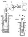
- FIG. 1ashows a schematic diagram of a measurement-while-drilling (MWD) embodiment of the system 10 of the present invention. It includes a downhole subassembly 20 that is suspended within the borehole 14 by a drill string 16 during drilling of the borehole 14 .
- the downhole subassembly 20is positioned as close as practical to the drill bit 12 .
- the drill bit 12is rotated by a downhole motor contained in the downhole subassembly and/or by rotating the drill string by a surface prime mover to drill the borehole 14 in the earth formation 18 .
- the prime mover and other components of the surface drilling rigare not shown.
- a preferred embodiment of the downhole assembly 20comprising various sensors and devices will be described later with reference to FIGS. 1b and 1c .
- Data from the downhole subassembly 20are telemetered by a downhole telemetry system (not shown) in the downhole subassembly 20 to an uphole telemetry element 30 .
- the uplink data telemetry pathis indicated by the broken line 27 .
- Data from the downhole subassembly 20are received by the uphole telemetry element 30 and passed to a surface processor 32 .
- a processor 32controls the output 34 such that the parameters of interest are recorded and displayed in the desired manner which is usually a plot of the parameters of interest as a function of depth within the borehole at which they are determined.
- the telemetry system utilized in the present inventionpreferably is a two-way telemetry system as disclosed in the United States Patent Application Serial No. 08/371,882.
- the processor 32also receives input data from the input element 36 which are telemetered downhole by a downlink telemetry path denoted by the broken line 29 to the downhole subassembly 20 .
- the use of a two-way communication systemis especially useful in changing reference data such as offset well data or even sensor response model data during the actual drilling operation.
- the system 10also includes a surface depth measurement system, such as a depth measure wheel and associated circuitry 28 .
- a depth measurement system(not shown) also is included in the downhole subassembly 20 which enable a downhole computer to more accurately correlate or compute various sensor measurements and parameters of interest to their respective depths or true locations within the borehole 14 at which such measurements are made.
- FIG. 1bshows a preferred arrangement of the various devices and sensors contained in the downhole assembly 20 , which is coupled between the drill bit 12 and the drill pipe 16 .
- the downhole assembly 20preferably contains a drill motor or mud motor 210 that is operatively coupled to the drill bit 12 via a drive shaft (not shown) disposed in a bearing assembly 212 which rotates the drill bit 12 when a pressurized drilling fluid 46a is passed through the mud motor 210 .
- the bearing assembly 212supports the radial and axial forces of the drill bit 12 , the downthrust of the drill motor 210 and the reactive upward loading from the applied weight on bit.
- a lower stabilizer 214preferably placed over the bearing assembly 212 , acts as a centralizer for the lowermost portion of the mud-motor assembly. In applications requiring drilling only vertical boreholes, usually no drill motor is used and the drill bit is rotated by rotating the drill pipe by a prime mover at the earth's surface.
- the downhole assembly 20preferably contains a plurality of sensors for providing measurements for various formation parameters and downhole conditions, a depth measuring device, and downhole geosteering devices that enable altering drilling direction without requiring retrieval of the drill string.
- the embodiment of FIG. 1bshows a kick-off assembly 224 and an upper stabilizer 226 placed between the drill motor 210 and the bearing assembly 212 .
- the function and operation of the stabilizers and the kick-off assembly in the context of this inventionwill be described later with reference to FIG. 1c.
- the downhole assemblypreferably has a module, generally referred by the numeral 216 , placed above the kick-off subassembly 224 and the upper stabilizer 226.
- This moduleincludes a resistivity device 218 for determining the formation resistivity near and/or in front of the drill bit 12 , a gamma ray device 220 for measuring the formation gamma ray intensity and an inclinometer 222 for measuring inclination of the module 216 .
- the resistivity measuring device 218preferably is of the type described in the United States Patent No. 5,001,675.
- This patentdescribes a propagation resistivity device having one or more pairs of transmitting antennas 218a' and 218a" spaced from one or more pairs of receiving antennas 218b' and 218b ".
- Magnetic dipolesare employed which operate in the medium frequency and lower high frequency spectrum.
- the transmitted electromagnetic wavesare perturbed as they propagate through the formation surrounding the resistivity device 218 .
- the receiving antennas 218b' and 218b"detect the perturbed electromagnetic waves.
- Formation resistivityis derived from the phase and amplitude of the detected signals.
- the detected signalsare processed by a downhole circuit contained within the downhole assembly 20 .
- the gamma ray device 220 and the inclinometer 222are suitably placed along the resistivity measuring device 218 in the module 216 .
- the inclinometer and gamma ray devicemay be placed at any other suitable place in the downhole assembly.
- the downhole assembly 20preferably contains an inertial guidance device, such as a gyroscopic device 230 , for determining the position of a known point in the downhole subassembly 20 during the drilling of the borehole 14 .
- a gyroscopic device 230Any other suitable depth measuring device, such as a magnetometer, may be deployed in the downhole subassembly for the purpose of this invention.
- a formation porosity measuring device and a formation density measuring deviceare provided above the drill motor 210 .
- the present systempreferably utilizes a formation porosity measurement device, such as that disclosed in the United States Patent No. 5,144,126.
- This deviceemploys a neutron emission source and a detector for measuring the resulting scattered neutrons. In use, fast neutrons are emitted into the surrounding formation. A suitable detector measures the neutron energy delay due to interaction with hydrogen atoms present in the formation. The device measures the neutron porosity ( ⁇ n ) of the formation.
- Other examples of nuclear logging devicesare disclosed in United States Patent Nos. 5,126,564 and 5,083,124.
- the formation density devicepreferably is the nuclear density device disclosed in the United States Patent No. 5,134,285.
- a deviceemploys a gamma ray source and a detector.
- gamma rays emitted from the sourceenter the formation where they interact with the formation and attenuate.
- the attenuation of the gamma raysis measured by a suitable detector from which density of the formation is determined.
- the system 10 of the present inventioncontains a number of other sensors, such as sensors for determining downhole temperatures, pressure, drill bit rotational speed, fluid flow rate through the mud motor, etc.
- the downhole assembly 20also contains devices which may be activated downhole as a function of the downhole computed parameters of interest alone or in combination with surface transmitted signals to adjust the drilling direction without retrieving the drill string from the borehole, as is commonly done in the prior art. This is achieved in the present invention by utilizing downhole adjustable devices, such as the stabilizers and kick-off assembly. One arrangement of such devices is shown in FIG. 1c.
- the deflection device 250contains an adjustable bit subassembly 252 that is coupled directly to the drill bit 12 .
- the drill bit subassembly 252has an associated control means which upon receiving appropriate command signals causes the drill bit 12 to turn from a current position 252' to a desired position 252" as shown in the exploded view of FIG. 1c1 .
- Such a deviceallows changing the drill bit direction relative to a fixed tool.
- the drill bit subassembly 250can effect relatively smaller changes in the drilling course.
- the downhole assemblyis provided with downhole adjustable lower and upper stabilizers 214 and 226 and an adjustable kick-off subassembly 224 .
- the lower and upper stabilizers 214 and 226preferably have a plurality of associated independently adjustable pads 214a and 226a as shown in the exploded figures 1c2 and 1c3 .
- Each adjustable padis adapted to be radially extended and contracted to any desired position by means within the downhole subassembly 20 , such as hydraulic means and/or electro-mechanical means, such as an electric motor.
- the stabilizer padsmay be made to move in unison and extended or contracted to desired positions.
- the kick-off subassembly 224is designed so that it may be turned at a deflection point 224a to a desired angle, as shown by the dotted lines 224a' in the exploded view of FIG. 1c4 .
- the adjustable pads 214a and 226a and the kick-off subassembly 224are controlled by their respective means which are responsive to selected downhole signals executed by a downhole computer and/or signals transmitted from a surface device.
- the lower adjustable pads 214, upper adjustable pads 226 and kick-off subassembly 224define a three point geometry, which enables steering the drill bit in any desired direction.
- the mud motor 210transfers power to the drill bit 12 via one or more hollow shafts that run through the module 216 .
- the hollow shaftenables the drilling fluid to pass from the mud motor 210 to the drill bit 12 .
- the mud motor 210may be coupled below the resistivity measuring device 218 or at any other suitable place.
- the system of the present inventionalso includes a suitable means, such as a bypass valve (not shown), which may be activated by the downhole computer during the drilling operation to control the fluid flow through the mud motor and, thus, control the rotational speed of the mud motor and hence the drill bit 12 .
- the various components of the downhole assembly 20are preferably interconnected modules, each such module containing various sensors and devices. Each module is contained in a fluid tight housing which shields the internal elements thereof from the borehole environment.
- a modular constructionis described in the U.S. Patent Application Serial No. 08/212,230.
- FIG. 1dthe system of the present invention in a wireline embodiment, generally designated by numeral 10'.
- the downhole subassembly 20is suspended within borehole 14 by the wireline 17 .
- Casing 19is positioned in the upper portion of the borehole 14 .
- the annulus between the casing 19 and the borehole 14is filled with cement which provides a hydraulic and pressure seal.
- a lubricator 22is affixed to the top of the casing 17 thereby providing a conduit through which the wireline 19 passes and also providing a means of containing any pressure within the borehole 14 .
- the wireline 17passes over a calibrated depth measure wheel 28' and is attached to a draw works (not shown).
- the depth measure wheel 28'performs the same functions as the depth measure wheel 28 described previously in the MWD embodiment of the invention.
- the draw workscooperates with the wireline to convey the downhole subassembly 20 along the borehole 14 in a manner well known in the art.
- the wirelinealso provides a communication path between the downhole subassembly 20 and the surface telemetry unit 30 .
- FIG. 2ashows a functional block diagram of the major elements of the downhole assembly 20 and further illustrates with arrows the paths of cooperation between such elements. It should be understood that FIG. 2a illustrates only one arrangement of the elements and one system for cooperation between such elements. Other equally effective arrangements may be utilized to practice the invention.
- a predetermined number of discrete data point outputs from the sensors 52are stored within a buffer which, in FIG. 2a , is included as a partitioned portion of the memory capacity of a computer 50 .
- the computer 50preferably comprises commercially available solid state devices which are applicable to the borehole environment.
- the buffer storage meanscan comprise a separate memory element (not shown).
- the sensor response relationships or "models"are stored within memory 48 which preferably comprises commercially available solid state storage devices suitable for the borehole environment.
- memory 48preferably comprises commercially available solid state storage devices suitable for the borehole environment.
- other reference datasuch as seismic data, offset well log data statistics computed therefrom, and predetermined drilling path also are stored in the memory 48 .
- a two way communication linkexists between the memory 48 and the computer 50 .
- the responses from sensors 52are transmitted to the computer 50 wherein they are transformed into parameters of interest using methods which will be detailed in a subsequent section hereof.
- the computer 50also is operatively coupled to certain downhole controllable devices d1 - dm , such as adjustable stabilizers and kick-off subassembly for geosteering and to a flow control device for controlling the fluid flow through the drill motor for controlling the drill bit rotational speed.
- certain downhole controllable devices d1 - dmsuch as adjustable stabilizers and kick-off subassembly for geosteering
- a flow control devicefor controlling the fluid flow through the drill motor for controlling the drill bit rotational speed.
- the sensors 52are usually axially spaced within the downhole subassembly 20 and operate simultaneously. The sensors 52 , therefore, do not provide measurement corresponding to the same borehole location at the same time. Therefore, before combining the sensor data, the computer 50 shifts the raw sensor data to a common reference point, i.e. depth correlates such data, preferably by utilizing depth measurements made by the downhole depth measurement device contained in the downhole subassembly 20 . Also, different sensors 52 usually do not exhibit the same vertical resolution. The computer, therefore, is programmed to perform vertical resolution matching before combining the sensor data. Any suitable method known in the art can be used to depth shift and resolution match the raw sensor data.
- the parameters of interestare then passed to the down hole portion of the telemetry system 42 and subsequently telemetered to the surface by a suitable uplink telemetry means illustrated conceptually by the broken line 27 .
- the power sources 44supply power to the telemetry element 42 , the computer 50 , the memory modules 46 and 48 and associated control circuits (not shown), and the sensors 52 and associated control circuits (not shown).
- Information from the surfaceis transmitted over the downlink telemetry path illustrated conceptually by the broken line 29 to the downhole receiving element of downhole telemetry unit 42 , and then transmitted to the storage means 48 .
- the telemetry transmission path between the downhole telemetry unit 42 and the uphole telemetry unit 30is the drilling mud column in the preferred embodiment.
- FIG. 2bshows a generalized flow chart of determining parameters of interest downhole and the utilization of such parameters in the context of this invention.
- the individual sensorssuch as the porosity, density, resistivity and gamma ray devices obtain base sensor measurement and calculate their respective parameters.
- the neutron porosity devicemay provide the value of the formation nuclear porosity ( ⁇ n ) and the density device may provide the formation density.
- Such sensor measurementsare retrieved by the computer according to programmed instruction for determining the parameters of interest.
- the computerreceives depth measurements from the downhole depth device 230 ( FIG. 1b ) and/or from the surface processor 32 ( FIG. 1a ) and correlates the sensor measurements to their respective true borehole depth as shown by the box 314 .
- the downhole computermatches the resolution of the depth correlated measurements. For example, neutron porosity on a sandstone matrix at a given depth resolution is matched to other sensor measurements in the downhole assembly.
- the computerthen transforms or convolves a selected number of measurements to determine desired parameters of interest or answers as shown by the block 318 .
- the parameters of interestmay include parameters such as the water saturation ( S w ), true formation porosity obtained from the neutron porosity ⁇ n and the formation density from the density device, flushed zone saturation, volume of shale in the formation ( V sh ), recovery factor index (" RFI "), amount of the drill string direction deviation from a desired borehole path, etc.
- the computeralso may be adapted to compare the borehole formation logs with prior well logs and seismic data stored in downhole memory and to cause the deflection elements (see FIG. 1b ) to adjust the drilling direction.
- the computer 50transmits selected answers to the surface 330 and takes certain corrective actions 332 , such as correcting the drilling direction and adjusting the drill bit rotational speed by adjusting the fluid flow through the drill motor.
- the surface processor 32receives the data from the downhole computer via the downhole telemetry and may send signals downhole to alter the downhole stored models and information, causing the downhole computer to take certain actions as generally shown by block 334 .
- the system described hereis a closed loop system, in that the answers computed downhole may be adapted to cooperate with surface signals and may be utilized alone or in conjunction with external information to take certain action downhole during the drilling operations.
- the computed answers and other informationis preferably stored downhole for later retrieval and further processing.
- the downhole computer 50is programmed to process measured data from the multiple sensors of different types using predetermined sensor response relationships.
- the downhole subassemblycontains sensors for detecting scattered gamma radiation spectra, thermal neutron flux, attenuation and phase shift of electromagnetic radiation, acoustic travel time, and an inclinometer and a three axis accelerometer.
- the response characteristics for any particular combination of sensorsis preferably formulated in the form of a response matrix.
- the response matrixis generated for any particular combination of sensors either with measurements within environmental test formations of known borehole and formation characteristics, or mathematical modeling of the tool sensor responses under known conditions, or both.
- the response matrixis programmed within the downhole computer.
- the response matrixmay change as borehole conditions change.
- the current inventionprovides means for changing the response matrix while drilling as will be disclosed in a following section.
- raw dataare recorded by one or more sensors during a sample time period. These data are next correlated to a common measure point and then arranged into a data matrix by the downhole computer and stored temporarily within the computer along with the depth of the common measure point at which the sensor measurements were made.
- the parameters of interestare then determined from the product of the response matrix and the data matrix, with the matrix multiplication being performed within the downhole computer.
- the response matrixcontains m rows and n columns and that the data matrix is one dimensional containing " m " rows.
- the parameter matrixwould be a one dimensional matrix containing " n " rows.
- Each element of the parameter matrixrepresents a computed parameter of interest.
- the computed parameters of interest and corresponding depthare then telemetered to the surface using a system such as a mud-pulse telemetry system and recorded at the surface as a function of depth within the borehole, or alternatively stored in a first downhole memory for subsequent retrieval at the surface, or simultaneously transmitted to the surface and stored in the first downhole memory means.
- the elements of the parameter matrixmight represent the resistivity, dielectric constant, bulk density, effective porosity and hydrocarbon saturation of the formation, the diameter of the borehole and the azimuth and inclination of the downhole subassembly.
- nthe number of parameters of interest.
- nthe number of parameters of interest.
- a plurality of raw data measurementscan be obtained from a single sensor such as a single electromagnetic transmitter-receiver array with the transmitter operating at a plurality of frequencies.
- nthe number of parameters of interest can be effectively telemetered or stored thereby requiring that each parameter of interest be computed downhole at each depth interval.
- Bandwidth and storage limitationsprevent telemetering and storage, respectively, of the raw data measurements m.
- Methods other than the previously described matrix manipulation methodmay also be used to combine raw sensor data with operational characteristics of the sensors to obtain parameters of interest.
- Parallel processing computing meansare ideally suited for processing or "reducing" large amounts of measured data to relatively small amounts of processed or “answer” data.
- Emerging neural network technologyis likewise suited for performing the stated tasks in a most efficient manner.
- the downhole subassembly 20comprises:
- the gross gamma ray activity of the formationis used as an indicator of the amount of shale within the formation and the spectral natural gamma ray detector is used to classify types of shale and to aid in the identification of other constituents of the formation.
- the neutron source and short-spaced and long-spaced thermal neutron detectorsare used as an indicator of formation porosity.
- the gamma ray source and long and short spaced gamma ray detectorsare used to measure the bulk density of the formation which measurements, in turn, is used to make a second determination of porosity.
- stand-off of the downhole subassemblyis determined using the acoustic stand-off sensor. These stand-off measurements are then used to correct the porosity and bulk density measurements for the adverse effects of stand-off.
- the responses of each of the above sensorsare, however, not a sole function of the parameter of interest being calculated from the response.
- the response of the gross natural gamma ray sensoris not only a function of the shale content of the formation but also a function of the other constituents of the formation which emit gamma radiation and, to a lesser extent, a function of the porosity of the formation.
- Subassembly stand-offis preferably measured by (a) employing a transducer to transmit a train of acoustic pulses azimuthally around the borehole and (b) measuring the travel time of each pulse as it reflects from the borehole wall and returns to the transducer.
- the response of the gross natural gamma ray sensoris not only a function of V sh but also a function of ⁇ e and the natural gamma ray activity of the rock matrix constituents f q .
- the constituents f qwill be referred to as a group representing the rock matrix using the symbol "Ma".
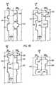
- C gr (V sh , ⁇ e ,Ma)F(V sh , ⁇ e ,M a ) where F(V sh , ⁇ e ,Ma) is a functional relationship illustrated hypothetically in FIG 3a .
- the shale fraction V shis plotted on the ordinate 80 as a function of measured count rate C gr which is plotted on the abscissa 70 .
- This functional relationshipis presented for three different rock matrices Ma 1 , Ma 2 and Ma 3 represented by the curves 64 , 66 and 68 , respectively.
- V sh1.0
- V sh1.0
- the curvewill be displaced to the left with increasing ⁇ e as depicted by the broken line curve 74. This, of course, assumes that the pore space of the formation is filled with fluid which is lower in gamma ray activity per unit volume than the rock matrix Ma 3 . Based upon the hypothetical example shown in FIG.
- K gris a constant depending upon the size and efficiency of the gamma ray detector
- a 1 , b 1 , and c 1are constants
- Mais the gamma count rate emitted per unit volume of the rock matrix.
- K gr , a 1 , b 1 , and c 1are "known" calibration constants which are either determined by operating the sensor in known test formations or are calculated using mathematical models of the sensors.
- ⁇ e , V sh and M aare the "unknown" parameters of interest to be determined.
- C gris, of course, a "measured" quantity.
- FIG. 3billustrates a hypothetical functional relationship between the count rate C n,ss measured by the short spaced thermal neutron detector and ⁇ e .
- Curves 92 and 94illustrate this relationship for two rock matrices Ma 1 and Ma 2 , respectively.
- V sh0.0 and there is no stand-off between the downhole subassembly 20 and the wall of the borehole 14 .
- d so0.0 for both curves 92 and 94.
- V shincreases in the formation, the curve will move to the left as depicted by the broken curve 96.
- Most shalescontain neutron absorbers in a greater concentration than most rock matrices.
- the measured count rate C n,sswill, therefore, decrease as V sh increases moving the curve to the left as illustrated.
- the sensor"sees" the intervening liquid as a portion of the formation with 100% porosity.
- the measured count ratedecreases for a given true formation porosity as d so increases.
- the curve 94 for the rock matrix Ma 2the curve will move to the left with increasing d so as depicted by the broken line curve 98 .
- the measured count rate C n,ssis, therefore, a function of ⁇ . as well as V sh , Ma and d so .
- C n,ssthere are other parameters which affect C n,ss such as the "excavation effect" as presented by F. Segesman and O. Liu (SPWLA Symposium, Dallas, May 2-5, 1971), but this effect is relatively small.
- a gas filled boreholewill drastically affect the response of the thermal neutron detector although this is not common in MWD operations and relatively rare in wireline operations.
- C n,ss ( ⁇ e ,V sh ,Ma,d so )F( ⁇ e ,V sh ,Ma,d so )
- F( ⁇ e ,V sh ,Ma,d so )K n,ss [(a 2 e -b 2 ⁇ e + c 2 e -d 2 V sh) + e 2 F(Ma,V sh + f 2 F(d so , ⁇ e )]
- K n,ssis a known constant which is a function of the neutron source strength and the thermal neutron detector size and sensitivity
- a 2 , b 2 , c 2 , d 2 , e 2 , and f 2are also "known" calibration constants either measured by operating the sensor in known test formations or computed by mathematical modeling of the sensor.
- F(M a , V sh )is a known functional relationship expressing the effects of Ma and V sh upon C n,ss
- F(d so , ⁇ e )is a known functional relationship expressing the effects of d so and ⁇ e upon C n,ss .
- the system response matrix [ S ]is stored within memory 48 .
- the matrix multiplication of equation (8)is performed within the computer 50 and only the five exemplary parameters of interest are telemetered to the surface, or stored within memory 46 for subsequent retrieval, or both.
- the number of energy windows used in the spectral natural gamma ray systemis usually at least three but can be as great as ten or twelve or even more.
- the number of acoustic travel time measurements T h for each stand-off determinationcan be quite large.
- the downhole subassemblyalso contains an array of multiple electromagnetic transmitters and multiple receivers. Measurements from these arrays are used primarily to determine the resistivity and dielectric constant of the formation which, when combined with other parameters, yield formation hydrocarbon saturation. If one or more acoustic transmitters and receivers are employed to obtain a third, independent porosity determination, large quantities of raw data will be used to compute a single "acoustic" porosity data point. If, therefore, a full set of formation evaluation and directional sensors are employed in the downhole subassembly 20 , it would not be unusual for the number of raw data measurements m to exceed the number of parameters of interest n computed from these measurements by several orders of magnitude.
- the computed parameters of interestmay be further used by the downhole computer as an input to determine other parameters of interest.
- V shmay be used to discriminate porosity and resistivity data to determine whether the formation being logged or drilled is a reservoir or non-reservoir rock.
- V shalso may be used to as a determinate to modify the transmission sequence of data uphole. For example, when V sh is below a predefined value, say 0.2, the transmission sequence would be preferential to convolved answers and when V sh is above the predetermined value, then it may be desirable to transmit sensor data from a selected sensors for use in real time by the surface processor.
- ⁇ bis the bulk density determined by a downhole sensor. The determination of the density porosity from the density assumes a knowledge of the matrix density and the fluid density.
- the matrix densitymay be determined from a density/neutron cross-plot or from a density/photoelectric cross-plot, which methods are known in the art.
- Matrix ⁇ ma and fluid ⁇ f densitiesmay be preprogrammed and/or downloaded real time into the downhole computer. This enables updating such correction and characterization parameters as required, which is important in MWD applications, because the downhole environment constantly changes during the drilling operations.
- Determination of gas bearing formationsmay be effected downhole by recognizing the "gas crossover effect" in reservoir rock exhibited on the neutron and density porosity logs.
- the presence of neutron - density crossovermay be configured as a single bit flag for transmission uphole and used as an input for selection of a porosity determination relationship.
- the element "c”is a constant having different values for different rocks. For example c is 1.0 for limestones and 0.9 for sandstone.
- the MWD subassembly 20contains a plurality of sensors 52 whose responses can be combined in real-time using previously discussed methods to obtain the parameters of interest of formation porosity, lithology and resistivity.
- reference datacomprises porosity, lithology and resistivity logs from surrounding wells, as well as the dip and strike of certain formations of interest. This information is stored in the second downhole storage means 48 which will be referred to as the reference data memory.
- the reference datacontains sufficient information to predict the depth within the drilling well at which formations of interest will be penetrated.
- Real-time measures of porosity, lithology and resistivity in the drilling wellare continuously compared or correlated with porosity, lithology and resistivity, along with formation strike and dip predicted by the reference data.
- the degree of correlation or correlation coefficientis telemetered to the surface. As long as correlation remains good, the driller is assured that the well is being drilled within the targeted fault block and that a fault plane has not been encountered. Should, however, the correlation between the drilling and reference parameters suddenly degrade, the driller must surmise that an unexpected fault plane has been penetrated. Changes in the drilling program can be made accordingly at the time the problem is encountered. Without real-time correlation of drilling and reference data, a significant amount of borehole could be drilled within the unexpected fault block resulting in wasted time and money.
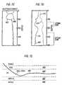
- FIG. 4aillustrates the geographical location of three existing wells identified by the numerals 100, 110 and 120 . North is specified by the arrow 99 .
- Combination natural gamma ray and resistivity logs measured in the existing wells 100, 110 and 120are shown in FIG. 4b across the shale sand sequence of interest and are identified in general by the numerals 100', 110' and 120' , respectively. More specifically, the natural gamma ray log 101 measured in well 100 shows the top of the sand labeled " A1 " at a depth indicated by the numeral 102 .
- the same gamma ray logshows the top of a second sand labeled " B1 " at a depth indicated by the numeral 104 .
- the resistivity log measured in the same well and identified by the numeral 103indicates no increase in resistivity in the A1 sand indicating that the sand is filled with saline water.
- the measured resistivitydoes show an increase in resistivity 107 in the top of the B1 sand indicating that the sand is partially saturated with oil with an oil-water contact at the depth 106 .
- the A1 sandis again seen on the gamma ray log 111 but with a top at a depth 112 which is shallower than the corresponding A1 sand top in well 100 .
- the B1 sandis also clearly delineated by the gamma ray log 111 with a top at the depth 114 which is likewise shallower than the top of the B1 sand in well 100 .
- the resistivity log 113 measured in well 110shows an increase in resistivity 115 in the A1 sand indicating oil with an oil-water contact at the depth 116 .
- the increase in resistivity 117 in the B1 sandlikewise indicates partial oil saturation with an oil-water contact again at a depth 106 .
- the combination natural gamma ray and resistivity log measured in well 120 and identified in general by the numeral 120'indicates the top of the A1 sand again at the depth 112 , the oil-water contact within the A1 sand again at the depth 116 , the top of the B1 sand at the depth 114 , and the oil-water contact within the B1 sand at the depth 106 .
- FIG. 4cdepicts a cross section X-X'-X" which includes existing wells 100 and 110 and the drilling well 130 .
- the surface of the earthis identified by the numeral 98 .
- the proposed path 130' of the drilling wellpenetrates the A1 sand where the bottom of the sand is above the oil-water contact at the depth 116 .
- the proposed path of the drilling wellpenetrates the B1 sand where the bottom of the sand is above the oil-water contact at the depth 106 . This location will, of course, maximize production from both sands.
- This abbreviated set of reference dataincludes the depths of the tops and bottoms of the formations of interest, the strike and dips of these formations, the projected tops and bottoms of these formations at the points of intersection with the drilling well, and the log readings within the formations of interest and within adjacent beds.
- a combination MWD gamma ray and resistivity logindicated in general by the numeral 130' , shows first that the drilling operation has reached a depth 136 .
- the MWD gamma ray log 131 and the MWD resistivity log 133indicate that the A1 sand has been penetrated with the top "up dip" at a depth 132 as predicted from the extrapolation of the offset log data.
- the drillerbased upon MWD measurements and projections and log readings from offset log data, is assured that the drilling operation is proceeding as planned and that no formation discontinuities have been encountered.
- FIG. 5aagain depicts the locations of existing wells 100 , 110 and 120 which are again shown in FIG. 5a with north being indicated by the arrow 99 and the northeast direction of upward dip of the formations of interest again being illustrated by the arrow 140 .
- the formationsare not continuous but are interrupted by a fault 141 .
- the top of the fault planeis shown in FIG. 5a and lies between the locations of the existing wells and the location of the drilling well 130' .
- FIG. 5bagain depicts the cross-sectional view X-X'-X " which illustrates the down-thrust portion of the fault to the northeast.
- the A1 sandis sealed from its counterpart A2 sand on the down-thrust side of the fault 141 .
- the B1 sandis likewise sealed from its counterpart B2 sand on the down-thrust side of the fault.
- the drilling well 130'has been drilled to a depth indicated by the numeral 136' with the target depth being indicated by the point 180 and the intended path for the borehole being designated by the broken line 178 .
- the well planis to penetrate the oil bearing portions of the A1 and B1 sands near the fault plane which will maximize the up dip production on the down-thrust side of the fault 141 .
- Prior to drillingit is not known whether the A2 sand contains oil.
- pertinent reference data from the logs of wells 100, 110 and 120are stored within the memory 48 of the downhole subassembly 20 . Preloaded offset well data can be enhanced by the aforementioned "look ahead" sensor measurements.
- coordinates of the fault planeare also stored within memory 48 .
- FIG. 5cillustrates the MWD gamma ray and resistivity logs identified by the numerals 231 and 233 , respectively.
- the current drilling depthis designated by the numeral 136' .
- the excursions 240 and 245 of the gamma ray logindicate that the A1 and A2 sands were penetrated as predicted by the offset log and seismic data.
- the low resistivity reading in the A2 sandindicates that this sand is saturated with saline water, at least at the intersection with the borehole 130' .
- MWD log readings predicted by the stored log and seismic reference data from the current drilling depth 136' to the final or "total" depth 180are illustrated as broken curves 248 for the gamma ray log and broken curve 246 for the resistivity log. If the actual MWD log readings agree with the predicted gamma ray and resistivity log readings 248 and 246 , respectively, the driller is assured that the borehole is tracking the targeted path. Should deviation between actual and predicted log readings occur, the driller has early warning that either drilling has deviated from the desired direction or unexpected geological anomalies have been encountered.
- the downhole computerhas stored therein the predetermined borehole path that is adapted to be updated by surface transmitted signals.
- the downhole computercontinually determines the true depth of the drill bit preferably from the downhole computed depth measurements as described and determines any deviation therefrom. If the deviation is greater than a predetermined amount, it causes one or more of the downhole deflection devices, such as the adjustable stabilizer pads and the adjustable bend, to correct the drilling direction.
- FIG. 6shows a functional block diagram for controlling the deflection devices.
- the directional response function model for the particular downhole assembly being used for drilling the boreholeis programmed in the computer.
- the computer 50cooperates with the sensing and control circuit 402 to cause the desired actuating control circuits 404a-n to control their respective devices 406a-n, in response to programmed instructions and/or surface transmitted signals during the drilling operations.
- the particular deflection devices chosen to adjust the drilling direction and the amount of change effected by each such devicedepends upon the nature of the desired change.
- the systemmakes closed loop decisions to adjust the downhole assembly to drill along a desired path and/or along a particular pay zone.
- FIGS. 7a-eshow another example illustrating how the present system may be utilized maintain the drilling within a desired pay zone 500 .
- FIGS. 7a-crespectively show examples of the gamma ray logs as a function of the borehole depth, preferably determined downhole.
- FIG. 7dshows water saturation and RFI logs computed by the downhole computer as described earlier.
- the parameter valuesare shown along the vertical direction as a function of the borehole depth or location.
- Track 452is the gamma ray log with a shale bed at the top followed by a mixed sand shale (fining) upward) sequence followed by a clean sand starting at depth of about 160 depth units.
- Tracks 454 and 456respectively show the shallow and deep resistivity values.
- Track 458 and 460respectively are the neutron and density porosities. The neutron and density crossover from 020 to 090 depth units indicates a gas bearing zone.
- Tracks 462 and 464respectively, depict downhole computed answers for water saturation Sw and recovery factor index RFI.
- FIG. 7eshows a horizontal portion of the borehole which relates to the logs shown in FIGS. 7a-d.
- Bed boundary avoidancecan be predicted from monitoring acoustic and/or the various resistivity responses. For example, at 200 depth units, the deeper resistivity track 456 shows the influence of the nearby water zone 482 .
- the downhole computerdetermines such a situation, it can cause the drill string to change the drilling direction away from the water zone 482 , which may be done by adjusting one of the deflection devices as described earlier.
- the optimal position of the wellbore within the pay zoneneeds to be determined.
- the downhole computermay be programmed to analyze the answer curves 462 and 464 to determine the borehole depth and the true vertical depth of the optimal water saturation S w . The computer then continues to control the drill string direction so as to maintain the drilling at the optimal vertical depth as shown by the curve or a predetermined range thereof.
- the system of the inventionutilizes a two-way communication system for transmitting data between the surface processor 32 and the downhole subassembly 20 .
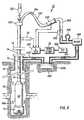
- the preferred two-way telemetry system and its use in the system of this inventionwill now be described in detail while referring to FIGS. 1, 2, 8 10 .
- FIGS. 1, 2, 8 10For convenience the elements that correspond between different figures are referred to by the same numerals.
- FIG. 8shows a schematic block diagram of the major components of the surface telemetry element 30 shown in FIG. 1 .
- drilling fluid or mudis the preferred communication medium and therefore the description provided herein relates generally to a telemetry system utilizing such a medium.
- Other communication paths, however,may be utilized for this invention.
- drilling mud 550ais drawn from a reservoir 550 by a mud pump 548 .
- the mud pump 548circulates mud at a high pressure through the standpipe conduit 544 and through the flexible kelly hose 532 , to the injector head 523 which terminates the upper end of the drill string.
- the surface telemetry element 30includes a downlink transmitter 540 and a uplink receiver 552 .
- the downlink transmitteris preferably located between standpipe conduit 544 and the flexible kelly hose 532 .
- the downlink transmitterpreferably is a variable frequency modulator. It, however, may be a pulsed modulator system, an acoustic wave generator, or a pressure pulsed system.
- the uplink receiver 552is positioned at a suitable place on the standpipe 544 . The operation of the transmitter and receiver will be described later.
- a surge protector 546is located between the standpipe 544 and the mud pump 548 in order to reduce pulsation caused by the reciprocating action of the pump.
- the drill string 16is supported by a crown assembly 521 which cooperates with a drawworks (not shown) to raise and lower and thereby convey the drill string along the borehole 14 .
- the drilling fluidis pumped under pressure through the drill pipe, the downhole subassembly 20 .
- the drilling fluidexits the drill string at the drill bit 12 and returns to the surface by flowing through the borehole drill string annulus and returns to the mud pit 550 via the return pipe 519 .
- Data from the downhole subassembly 20are transmitted to the surface by a modulated signal induced downhole within the mud column and subsequently detected at the surface by the uplink receiver 552 .
- Data and commands from the surfaceare transmitted simultaneously downhole as frequency modulated wave train induced in the mud column by the downlink variable frequency modulator transmitter 540 and subsequently detected downhole by one or more pressure transducers.
- Signals from the depth indicating device 28are transmitted to the junction box 554 which cooperates with the surface processor 32 as described later.
- the surface processor 32cooperates with the downlink transmitter 540 through the junction box 554 and also receives signals from the uplink receiver 552 through the junction box 554.
- An input/output unit 558serves as means for entering the parameters into the processor 32 as well as means for recording and displaying parameters of interest determined by the system of the invention.
- the downhole portion of the telemetry systemhas a downlink receiver 42a and an uplink transmitter 42b .
- the downlink receiverincludes one or more pressure transducers and is preferably mounted in close proximity to the downhole computer 50 .
- the uplink transmitterwhich preferably has a poppet valve of a positive displacement mud pulse transmission system, is designated by numeral 42b .
- the uplink transmission systemmay comprise a variable frequency modulator, an acoustic wave generator, or other pressure pulsing means compatible with the mud column communication path. If other communication path are used, the transmission and receiving means compatible with the selected communication path are likewise used.
- the uplink communication pathwhich includes frequency modulated pressure pulses induced within the mud column, is illustrated conceptually by the dotted line 29 .
- the downlink communication pathwhich includes the frequency modulated pressure wave train induced within the mud column by the variable frequency modulator transmitter, is illustrated conceptually by the dashed line 27 .
- FIG. 9shows three pressure wave trains within the mud column with relative pressure amplitude being plotted as a function of time.
- the curve identified by the numeral 580represents a frequency modulated signal induced within the mud column by the positive pulse uplink transmitter 42b .
- the curve denoted by the numeral 582represents a frequency modulated wave train induced within the mud column by the downlink variable frequency modulator transmitter 540 . If wave trains 580 and 582 are simultaneously induced within the mud column, a composite wave train represented by the curve 584 will be detected by both the uplink receiver 552 and the downlink receiver 42a .
- the composite wave trainis encrypted using methods and apparatus of the invention such that uplink data can be extracted by the surface computer 32 and downlink data can be extracted by the downhole computer 50 .
- processing at either the surface or downhole computerscan be "tuned" to the desired carrier frequencies. Stated another way variable frequency modulator type and pulse type transmission sequences can reside on, and be decoded from, one transmission channel.
- variable frequency modulator downlink transmitter 540is shown in FIG. 10 .
- the transmitter 540is connected between the standpipe 544 and the flexible kelly hose 532 preferably with knock on connector 594 being used to connect with the stand pipe.
- This means for connectionpermits easy access at the rig site for replacement and configuration of the internal transmitter/turbine assembly.
- the housing 592is preferably pressure rated at 1.400 mg force cm -2 (20.000 psi) and is approximately 0,8 m (2.5 feet) in length or even shorter so as not to interfere with the movement of the kelly hose 532.
- a handle 596is provided for case in handling by personnel at the rig site.
- the transmitter/turbine assemblyidentified generally by the numeral 501 , is triaxially mounted within the housing 592 .
- the transmitter portion of this assemblycomprises a rotor/stator, driving motor and electronic components used to regulate the modulation of the carrier/data wave train.
- This sectionis sealed with o-rings 503 within the housing 592 is accomplished by means of a cable in which one end penetrates the housing 592 at the feed through 598 and contacts the transmitter at internal connector 504 .
- the turbine or power supplying section, 506is located "up stream" from the transmitter section 502 . In this embossment, the flow of the drilling mud provides power to the transmitter 502 . In an alternate embodiment, power is supplied directly to the transmitter 502 .
- poweris supplied directly to the transmitter in parallel with the data transmission cable through feed through 598 and connector 504 .
- This embodimentmay, however, compromise the intrinsic safety of the device and may also shorten the life of the drive motor unless a switch (not shown) activated by the flow of the mud is employed.
- a switch(not shown) is used to activate the transmitter only when a predetermined pressure level within the standpipe 44 is exceeded.
- the downlink transmission sequencesends the downhole computer reference parameters such as the absolute depth at which the downhole assembly 20 is located within the borehole, the current weight of the mud, and the resistivity of the mud.
- the latter two parametersare used in the previously defined sensor response models and sensor combination models which are stored within the second downhole storage means. Additional information such as the command identifying which stored sensor response models or, more importantly, which stored sensor combination models should be used to process the raw sensor response data over the next drilling interval.
- transmission sequenceswill switch to a single bit transmission triggered by relative depth intervals measured by the depth indicator 28 or 230 ( FIG. 1b ).
- the previously described absolute depth measurement stored in a time/depth file of the downhole computer 50is reconciled with the transmitted incremental depth indications, which allows the downhole computed parameters of interest to be tracked with depth within the borehole at which they are determined.
- commands which are not data intensivecan be transmitted to the downhole subassembly 20 while drilling.
- the computed parameters of interestare transmitted by the uplink transmitter 42b where they are sensed by the uplink receiver 552, transferred to the junction box 554 and then to the surface computer 32 for possible additional processing and then to the input/output unit 558 wherein they are displayed preferably as a function of depth thereby forming a well log.
- the two-way communication system as disclosedgives great flexibility in the management of data transmitted, downlink as well as uplink. Many decisions can be made in real time that are not possible using prior art systems. Finally, by changing key parameters of sensor response models or sensor combination models, while drilling, the accuracy and the precision of measured parameters of interest are maximized.
- the processor 32 , downhole computer 50 and the two-way communication system described abovecooperate to optimize.
- the use of limited telemetry bandwidth or limited downhole storage capacity to transfer to the surface(a) formation evaluation data, (b) data pertaining to the drilling operation and (c) downhole subassembly operations.
- the accuracy and precision of parameters computed downholeis optimized by adjusting models and algorithms stoned downhole based upon changing environmental conditions during the drilling operations. A method to achieve such optimization is described below.
- the downhole computeris used to transform raw sensor response data into formation evaluation, drilling dynamics and bottom hole assembly parameters of interest. Transformation models may be divided into two types. The first type will be referred to as "sensor response models" for each sensor. As an example, a sensor response model for a nuclear sensor compressing a neutron source and a thermal neutron detector is used to transform the primary sensor measurement, which is counting rate, into an "engineering" parameter which is related to the number of hydrogen nuclei per unit volume of earth formation in the vicinity of the sensor.
- the second type of transformation algorithmwill be referred to as the "sensor combination model" which, as an example, might comprise an algorithm for combining hydrogen index determinations from a thermal neutron sensor with formation acoustic compressional wave velocity from an acoustic sensor to yield the parameters of interest which are formation porosity and formation lithology.
- Sensor response and sensor combination modelscan reside in the memory of the downhole computer 50 .
- these modelsare stored in a second downhole storage means.
- This second downhole storage meanscooperates with the downhole computer and the downlink of the telemetry system in a manner which will be detailed in following sections of the disclosure.
- the corresponding depths within the borehole at which the raw sensor data are measuredare also tracked.
- Depth of the bottom hole assemblyis telemetered to the downhole subassembly thereby providing means for assigning a corresponding measure depth to each computed parameter of interest.
- the total volume of datais compressed thereby reducing demands on the system uplink telemetry and downhole storage capacity.
- the two way communication linkis used to manage the acquisition and the transmission of data to the surface thereby further optimizing the utilization of available uplink telemetry and downhole storage capacity.
- mud weight and mud chemistrycan significantly affect the response characteristics of one or more of the downhole sensors.
- baritebarium sulfate
- the downlink communication channelprovides means for making thee parametric changes from the surface without interrupting the drilling operation.
- changeswill be categorized as one of three levels depending upon the amount of data that must be transmitted.
- a sensorwhich responds according to a first sensor response model if the drilling mud contains barite and to a second sensor response model if the mud contains no barite. Both sensor response models are stored in downhole memory. The active sensor response model can therefore be changed by the transmission of a single bit command from the surface. Such changes requiring minimal downlink transmission will be classified as level one.
- a sensorwhose response equation comprises a polynomial relationship which is again stored downhole. The coefficients of the terms of the polynomial are a function of the barite content of the mud.
- the values of the polynomialcan be changed based upon prior knowledge of mud barite content by using the downlink telemetry. This requires the transmission of considerably more data than the first example in order to properly define the coefficients and will be classified as lever two.
- the entire combination response model which is stored downholemust be varied as a function of the mud barite content. This involves the transmission of a considerable amount of data and will be classified as level three.
- Downlink transmissioncan be made during different phases of the drilling operation depending upon the level. As an example, it is desirable to perform level three and possibly level two transmissions when the drill string is not rotating. This minimizes interference from the drill string operational noise as will be discussed in a following section.
- the amount of raw sensor response data generated per depth interval of boreholegreatly exceeds the corresponding volume of parameters of interest or "answer" data computed from the sensor response data.
- Using the downhole computer 50 of the current invention to transform raw sensor response data into parameters of interestincreases the usage efficiency of limited bandwidth and downhole storage capacity of current MWD systems.
- MWD parametersThe efficiency of usage can be further increased by using data acquisition management and data transmission management techniques for various classes of MWD parameters as discussed below.
- the classes of MWD parameters of interestare divided into three categories which are (1) formation evaluation, (2) drilling dynamics and (3) bottom hole assembly operations.
- Formation evaluation parametersinclude formation porosity, hydrocarbon saturation, lithology, rock properties, formation dip and the like.
- Drilling dynamicsinclude directional information, information concerning drill bit wear, bit vibration and stand-off from the borehole, torque, weight on the bit, speed of rotation, temperature, pressure inside and outside of the drill string, and indications of bounce, sticking and slipping of the drill bit.
- the first two classes of MWD dataare usually tracked as a function of corresponding depth within the borehole.
- MWD systemswhich comprise sensors to measure all classifications of MWD measurements
- drilling dynamic information and possibly directional informationmay be of primary importance while formation evaluation parameters are of secondary importance.
- drilling dynamic information and possibly directional informationmay be of primary importance while formation evaluation parameters are of secondary importance.
- directional informationis critical while formation evaluation parameters are of secondary importance.
- bottom hole assembly operations measurementsare the prime parameters of interest while formation evaluation and drilling dynamics measurements are not needed.
- the inventionallows the driller to control, in real-time from the surface, the acquisition and transmission of the three classes of parameters of interest.
- This optionis again provided by the downlink telemetry means between the surface and the downhole subassembly containing the sensors.
- the drillercan select with downlink commands the sensor measurements and corresponding computed parameters of interest to be transmitted to the surface, or stored downhole, depending upon the particular phase of the drilling operation.
- the acquisition and transmission of formation evaluation parameterscan be activated and the acquisition and transmission of drilling dynamics and bottom hole assembly parameters can be suppressed by surface commands transmitted over the downlink telemetry means. This devotes the full band width capacity and the downhole storage capacity of the system to formation evaluation parameters thereby yielding maximum vertical resolution of formation parametric measurements.
- Similar selection commandscan be sent to optimize drilling dynamics measurements or bore hole assembly operations measurements, or any desired combination of the three classes of MWD measurements. In some circumstances, it might be desirable to telemeter only the selected parameters of interest and store downhole all parameters of interest for subsequent retrieval at the surface.
- the current inventionemploys a two way communication system between the surface and the downhole sensors of the MWD system.
- the uplink portioncomprises any type of MWD telemetry system, such as a mud pulse system, to telemeter to the surface parameters of interest computed downhole from the measured sensor response data.
- the downlink portionprovides means for sending selection commands to the downhole elements of the system. These commands define which specific parameters of interest are to be telemetered to the surface, or optionally stored in downhole memory, or both.
- the telemetry downlinkallows data acquisition management and data transmission management techniques to be employed thereby further optimizing the use of available capacity of the uplink telemetry as well as downhole storage capacity.
- the downlinkalso provides means for varying parameters of the sensor response models and the sensor combination models as a function of mud weight, mud chemistry, mud resistivity, or any other parameter which affects sensor response and which is measured at the surface. Furthermore, drilling parameters such as weight on bit and torque, which are measured at the surface, can be telemetered to the downhole subassembly for use in maximizing the effectiveness of the drilling operation.
- the downlink element of the two-way communication systemcan be used to input data into the downhole computer 50 .
- dataincludes, but is not limited to, real time data management commands which optimize the use of the downhole storage capacity and the uplink telemetry capacity of the system.
- Measurements made at the surfacecan also be input into the downhole computing means.
- Such datacomprises mud information, absolute depth measurements, and other measurements which are made at the surface and are utilized in subsequent downhole calculations.
- Measurements from downhole sensorscan provide formation evaluation input data to the downhole computer 50 .
- Formation evaluation input datainclude responses of electromagnetic sensors comprising multiple antenna, multiple receivers and multiple transmitter-receiver configurations. The response data include the amplitude and phase of electromagnetic energy emitted from transmitters as pulses or compensated waves. Formation evaluation input data further include responses of nuclear sensors. Such sensors can comprise either continuous or pulsed sources of neutrons and detectors which respond to thermal neutrons, epithermal neutrons, fission neutrons and to capture inelastic scatter gamma radiation resulting from the neutrons interacting with nuclei in the borehole environs.
- Nuclear sensorscan also comprise continuous or pulsed sources of gamma radiation and detectors which respond to gross gamma radiation or the energy spectra of gamma radiation induced by these sources within the borehole environs.
- Nuclear sensorscan further comprise gamma ray detectors which respond to the gross or energy spectrum of natural gamma radiation present within the borehole environs. Multiple nuclear sensors can be employed.
- Formation evaluation input datastill further includes the responses of one or more acoustic sensors.
- Such sensorscomprise one or more transmitters which emit focused or non-focused pulses or trains of acoustic energy into the borehole environs and receivers which respond to the amplitudes and travel times of various acoustic-wave components induced within the borehole environs.
- Transmitterscan emit energy at one or more frequencies and one or more transmitter-receiver spacings can be employed.
- Measurements from downhole sensorscan provide directional input data for the downhole computer 50 .
- Directional sensorscan respond to acceleration, pressure, temperature, flow of fluids into and out of the borehole, orientation of the downhole assembly within the borehole, internal navigation signals and the strike and dip of beds penetrated by the drill bit.
- Downhole sensorsalso provide a plurality of drilling dynamics input data for the downhole computer 50 .
- These datainclude mud properties such as the temperature and pressure of the mud within and outside of the downhole subassembly.
- Drilling dynamics sensorsalso respond to weight on the drill bit, the speed of rotation of the drill bit, as well as acceleration, torque, vibration and stand-off of the drill bit.
- Downhole sensorsalso provide input data for the downhole computer 50 pertinent to various bottom hole assembly operations including formation testing and controlled drill bit steering.
- Data from external sourcescan be input to the downhole computer 50 .
- These datacan comprise offset well log data, seismic data and directional well plan data which are stored within downhole memory means for retrieval as needed by the downhole computer 50.
- the aforementioned data inputs to the downhole computer 50are used to derive environmental parameters of interest. These parameters include, but are not limited to, properties of the mud, porosity of the formation, bulk density of the formation, liquid hydrocarbon saturation of the formation, gas saturation of the formation, rock properties of the formation, photoelectric factor of the formation, concentrations of elements within the formation, eccentricity of the downhole subassembly within the borehole, conditions of the drill bit, whirl of the drill bit, the efficiency of the drilling operation, bending of the drill string, rugosity and shape of the borehole, bit bounce, sticking and slippage of the drill string, the presence and thickness of mud cake, and formation permeability.
- the uplink element of the telemetry unit 42also permits real time decisions concerning bottom hole operations to be made. Such decisions include changing drilling dynamics, confirming various bottom hole operations, and modifying the drilling program for safety reasons. Real time drilling dynamics and formation evaluation parameters can be used in geosteering of the drill bit.
Landscapes
- Life Sciences & Earth Sciences (AREA)
- Engineering & Computer Science (AREA)
- Geology (AREA)
- Mining & Mineral Resources (AREA)
- Physics & Mathematics (AREA)
- General Life Sciences & Earth Sciences (AREA)
- Environmental & Geological Engineering (AREA)
- Fluid Mechanics (AREA)
- Geochemistry & Mineralogy (AREA)
- Geophysics (AREA)
- General Physics & Mathematics (AREA)
- Geophysics And Detection Of Objects (AREA)
Description
- The present invention relates to a measurement-while-drilling downhole assemblyfor drilling a borehole through earth formations, comprising a plurality of formationevaluation sensors for providing measurements relating to characteristics of the earthformations surrounding the drilling assembly during drilling of the borehole acomputer in the downhole assembly and to a method for drilling a borehole throughearth formations, comprising measuring characteristics of the earth formationssurrounding a downhole assembly of drilling assembly during drilling of theborehole with a plurality of formation evaluation sensors.
- The present invention relatesparticularly to a system of drilling boreholes having a measurement-while-drilling("MWD") system wherein drilling and formation data and parametersdetermined from various downhole measuring devices are transformeddownhole into selected parameters of interest or "answers" which aretelemetered to the surface or stored downhole for subsequent retrieval or both.In an alternate embodiment, measurements are depth-correlated, utilizing depthmeasurements made downhole for improving accuracy of the measurementsand the parameters of interest. The measurements and/or parameters are alsocorrelated with stored reference data for providing additional informationpertaining to the drilling operations and the formation characteristics. Thesystem also is adapted to determine the drill bit location relative to the desireddrilling path and to adjust the drilling activity downhole based on suchdetermination.
- To obtain hydrocarbons such as oil and gas, boreholes are drilled byrotating a drill bit attached at a drill string end. A large proportion of thecurrent drilling activity involves directional drilling, i.e., drilling deviated andhorizontal boreholes to increase the hydrocarbon production and/or to withdraw additional hydrocarbons from the earth's formations. Modern directional drillingsystems generally employ a drill pipe having a drill bit at the bottom that isrotated by a drill motor (commonly referred to as the "mud motor").Pressurized drilling fluid (commonly known as the "mud" or "drilling mud") ispumped into the drill pipe to rotate the drill motor and to provide lubrication tovarious members of the drill string including the drill bit. As required the drillpipe is rotated by a prime mover, such as a motor, to facilitate directionaldrilling and to drill vertical boreholes.
- A plurality of downhole devices are placed in close proximity to the drillbit to measure formation properties, downhole operating parameters associatedwith the drill string and to navigate the drill bit along a desired drill path.Downhole devices, frequently referred to as the measurement-while-drilling("MWD") devices, are typically coupled between the drill bit and the drill pipealong with the mud motor, kick-off device and stabilizers. For convenience, allsuch devices are collectively sometimes referred herein as the "downholesubassembly." The MWD devices typically include sensors for measuringdownhole temperature and pressure, an inclination measuring device fordetermining the inclination of a portion of the drill string, a resistivity measuringdevice to determine the presence of hydrocarbons against water, and devicesfor determining the formation porosity, density and formation fluid conditions.
- Prior to drilling a borehole, substantial information about the subsurfaceformations is obtained from seismic surveys, offset wells, and prior drilled boreholes in the vicinity of the current borehole. The borehole is then usuallydrilled along a predetermined path based upon such prior information. Duringthe borehole drilling, the downhole subassembly transmits information aboutthe various downhole parameters, which are typically analyzed and correlatedwith other parameters at the surface to decide whether the drilling path needsto be adjusted. To adjust the drilling path, the drill string is usually retrievedfrom the borehole and then certain mechanical devices, such as kick-offsubassemblies and stabilizers, are adjusted to alter the drilling direction.Stopping the drilling operation and retrieving the drill string to adjust the drillingdirection results in great expense. Additionally, surface-measured downholedepth of the drill bit is typically utilized to take corrective actions. Surface-measureddepth readings rely on the drill pipe length, which over several hundred metres(thousand feet) may have an error of several metres (feet) (5 to 15m or 15 to 50 feet) from the truelocation, which is highly undesirable, especially for horizontal drilling throughrelatively narrow formations. Thus, it is desirable to have a drilling systemwhich provides more accurate measure of the depth of the downholesubassembly and means for adjusting the drilling direction without retrieving thedrill string from the borehole.
- The downhole subassembly usually transmits information about thevarious downhole parameters to the surface by an uplink telemetry via the mudcolumn in the drill string or electromagnetic means. The current telemetrysystems such as the mud-pulse telemetry systems are capable of transmitting typically one bit per second, which greatly limits the ability to transmit a vastamount of useful information about the downhole formations and downholeconditions to the surface during the drilling operation.
- To accurately determine the properties of the formations along theborehole, such as porosity, permeability, hydrocarbon saturation and othergeophysical properties and the borehole profile, the drilling activity isintermittently stopped, the drill string is retrieved and wireline logs are obtainedby traversing wireline tools through the borehole. The wireline tools contain aset of downhole devices such as resistivity devices, porosity and permeabilitymeasuring devices and acoustic devices. Such devices transmit a vast amountof data relating to the formations and the downhole conditions via a hightransmission rate telemeter system to the surface, where the data istransformed into certain parameters of interest, which parameters are thenutilized to aid in the drilling of the borehole and to determine the formationlithology, producibility of the pay zones, etc. The wireline systems provide amethod for conveying the devices in the borehole and means for transmittingdata at very high data rates.
- Current wireline systems contain multiple sensors and complexprocessing algorithms to determine formation properties along the borehole.Examples include electromagnetic sensors comprising multiple transmitters andmultiple receivers which measure attenuation and phase shift of the transmittedsignals as they traverse the formation. Acoustic sensors which measure attenuation, phase shift and the full wave form of acoustic signals traversingthe formation and borehole are also used. Nuclear sensors are used to measurethe natural gamma ray energy spectrum of the formation which is indicative ofshale content, shale type and other parameters of interest. Nuclear sensorscomprising chemical neutron or isotopic gamma ray sources and neutron orgamma ray detectors are used to measure a plurality of geophysical parameters.Pulsed neutron sources and gamma ray accelerators are used in other types ofnuclear sensors. All of the aforementioned sensors used in the wireline toolsare data intensive. When such measurements are made simultaneously with asingle pass of a multiple sensor wireline device along the borehole, massiveamounts of raw data are generated per depth interval of borehole traversed.
- With some wireline systems, raw sensor data are transmitted to thesurface of the earth over the logging cable for subsequent processing to obtainthe multiple parameters of interest. As examples, current wireline telemetrysystems using seven conductor electrical logging cable can telemeter data tothe surface at a rate of 500 kilobits to 1000 kilobits per second. Use of fiberoptic cables substantially increases the data transmission rate. Such wirelinetelemetry systems have large telemetry bandwidths which enable the use ofmultiple sensors and transmission of the data to the surface for processing.
- However, in boreholes in which the pressure of the well is aboveatmospheric pressure at the surface, the logging cable must pass through apressure-containing device known in the art as a "lubricator." The cross sectional area of current multiple conductor and fiber optic cables is such thatthe lubricator cannot contain surface well pressures of several hundred kg force cm-2 (thousand psi) andstill permit the cable to move freely through the lubricator. Single conductorcables have smaller cross-sectional areas which allow the lubricator to maintainpressure control and also allow the cable to move freely through the lubricator.Therefore, smaller diameter single-conductor cables are usually used in suchhigh pressure wells. Telemetry bandwidths of single conductor wirelinesystems are substantially lower than those comprising seven conductors orfiber optic cables.
- Simultaneous measurements using multiple, data-intensive sensors cangenerate amounts of raw data which exceed the telemetry capacities of singleconductor wireline systems. As a result, the raw data is sometimescompressed before being telemetered to the surface, which results in a loss ofvertical resolution of the measurements and/or a degradation in accuracy of themeasurements. Vertical resolution and accuracy can be preserved bycorrelating multiple measurements downhole in such wireline systems.
- Wireline logs from existing wells are frequently correlated to selectlocations and borehole profiles of subsequent wells. For example, logcorrelations often define the presence of faults and aid in the delineation andmapping of fault blocks. Log correlations can also reveal anomalies such aslocalized structures or "lenses" which might act as traps for hydrocarbons.However, such wireline correlations often do not reveal critical structural aspects of the field as will be illustrated and further discussed in subsequentsections of this disclosure. Correlation of measurements during drilling of theborehole can provide more accurate measure of such anomalies. It is thereforedesirable to determine parameters of interest downhole and correlate suchparameters of interest with prior well logs during the drilling operation.
- Seismic data are frequently used in developing existing oil and gas fields.Seismic data are usually the prime source of information upon which decisionsare based in choosing locations for exploratory or "wild cat" wells, but seismicdata are also used in the development of existing fields. The correlation of welllog data and seismic data can be used to detect structural anomalies whichwould go undetected with conventional well log correlation methods. Thespatial resolution of seismic measurements is poor when compared to wirelinemeasurements. Although well log and seismic correlations are used to selectlocations and target zones of development wells, poor spatial resolutionpresents a problem in defining the target formation with the accuracy andprecision required by the driller. Correlation of downhole-computed parametersof interest with seismic data during drilling of the borehole can address someof these problems. The results may be stored downhole for later retrievaland/or selectively transmitted uphole during drilling of the borehole.
- Thus, there is a great need to determine various parameters of interestdownhole during the drilling of boreholes because massive data generated bythe sensors cannot be transmitted uphole during the drilling operation. As noted earlier, wireline logs are typically made intermittently during the drillingoperation and such logging requires that the drill string be removed from theborehole prior to logging. Logging after completion of the drilling operationoften reveals that the target formation or formations have been missed. Inaddition, unexpected zones such as high pressure formations or salt zones, canbe encountered during the drilling operation. These formations and zones canadd costly delays to the drilling operation and endanger drilling personnel andequipment. Also, damage to the borehole can occur during logging and drillingrig time and logging equipment time is wasted during stand-by periods for eachoperation.
- Many of the above-noted problems can be overcome by measuringvarious formation-evaluation and drilling parameters during the actual boreholedrilling operation. Formation evaluation via measurements-while-drilling (MWD)logs combined with offset wireline logs and seismic data can provide, in realtime, information on anomalies, such as fault planes or formation lenses. Suchmeasurements can also indicate to the driller that high-pressure formations orsalt zones are being penetrated, thereby giving the driller time to take remedialsteps, such as adjusting the weight and salinity of the drilling fluid, beforethese zones adversely affect the drilling operation. Real-time measures ofdrilling dynamics data provide the driller with information concerning theefficiency of the drilling operation. Furthermore, borehole directionalinformation, combined with real-time formation evaluation parameters, offset wireline log data and seismic data can be extremely useful in assisting thedriller in reaching the targeted zone of interest. These and other applicationsinvolving the correlation of offset wireline data, seismic data and any other typeof reference data with measurements made while drilling will be discussedfurther herein.
- These MWD systems provided directional information and a limitednumber of formation evaluation type measurements. In the past decade,additional sensors and services have been added. In many respects, thesophistication of the sensors is comparable to their wireline counterparts inspite of the harsh environment experienced in using such sensors in the drillingenvironment. Current MWD systems do not combine multiple sensormeasurements because current MWD telemetry does not have the capacity tosimultaneously transmit a plurality of full acoustic wave forms or gamma rayenergy spectra or electromagnetic wave attenuation and phase shift data, or acombination thereof, to the surface for processing to determine parameters ofinterest at intervals sufficient to obtain the required vertical resolution of thepenetrated formations. The simultaneous transmission of drilling managementsensor information such as directional information, weight on the drill bit, andother non formation evaluation type measurements further overloads currentMWD telemetry transmission rates, which are of the order of 2 to 60 bits persecond. Furthermore, it is not feasible to store copious amounts of rawdownhole sensor data for subsequent retrieval and processing due to relatively limited storage capacity of current MWD systems.
- MWD means for making multiple formation and borehole evaluation typeparametric determinations comparable to current wireline measurements requirethe computation of the desired parameters downhole, and the transmission ofthe computed parameters of interest to the surface. By using downholecomputational means and methods, the transmission requirements are reducedby orders of magnitude in that only "answers" are telemetered rather than rawdata. This type of downhole computation is also applicable to other types ofnon- formation evaluation type measurements such as signals indicative of theoperational characteristics of the downhole equipment as well as measurementsindicative of drilling direction and efficiency.
- There are numerous references in the prior art directed toward themeasurement of formation parameters while drilling and the use of thesemeasurements to "steer" the drill bit within a formation of specifiedcharacteristics. An exemplary system is disclosed in U.S. Patent No.5,163,521 to Randal H. Pustanky et al. One basic technique comprises thetransmission of measured formation parameters to the surface in real-timethereby allowing the driller to compare measured and targeted formationparameters and to manually adjust the direction of drilling based upon thiscomparison by the use of directional commands from the surface. A secondbasic technique comprises the continuous comparison of measured and targetformation parameters downhole and the automatic adjustment of the drilling direction based upon these comparisons. United States Patent No. 5,332,048to Lance D. Underwood et al teaches the measurement of geologicalparameters while drilling, the use of a downhole microcontroller which ispreprogrammed with a desired range of formation characteristics or with thedesired borehole inclination or target area, the continuous comparison ofmeasured and preprogrammed formation characteristics, and the adjustment(either automatically or by commands from the surface) of the drilling directionbased upon these comparisons. The formation evaluation features of this andother references directed toward "geosteering" are rather fundamental in thatthey are designed to identify the formation that is being penetrated (e.g. sandor shale) for steering purposes rather than to perform a detailed analysis of theformation.
- WO 93/12318 describes a method and an apparatus for automatically controlling the directionof advance of a rotary drill to produce a borehole profile substantially as preplanned withminimal curvature while maintaining optimum drilling performance. The system for controlleddrilling of a borehole comprises a drill string, a drill bit, means for rotating the drill bit, meansfor storing a planned path, means for obtaining information for providing a profile of a drilledpath of the borehole, means for comparing the drilled path with the planned path and forgenerating a correction signal representing the difference between the drilled path and theplanned path, and means responsive to the correction signal to cause the drilling means tocalculate a corrected path to cause the drilled borehole to coincide with the planned path.
- The current invention is directed toward the use of a downhole computerwithin a measurement-while-drilling (MWD) device to process data from theresponse of a plurality of sensors of different types. The basic concepts of theinvention are also applicable to wireline operations, particularly where thenumber of sensors and the raw data output of these sensors exceed availablewireline telemetry capacity. Types of sensors applicable to the inventioninclude, but are not limited to, electromagnetic, acoustic, nuclear, directional,temperature and pressure. Sensor measurements are made essentially simultaneously with each sensor, and the sensor responses are processed usingthe computational means within a downhole subassembly to obtain measuresof formation and other properties and functions of interest. These computedparameters or "answers" are then transmitted to the surface by a suitableMWD telemetry system such as a mud-pulsed system. In an alternateembodiment, the answers are stored in a first downhole storage means of theMWD system for subsequent retrieval when the drill string is removed or"tripped" from the borehole. In still another embodiment, the answers are bothtelemetered to the surface and simultaneously stored within the first downholestorage means.
- The current invention is further directed toward the downholecombination of reference data, stored within a second downhole storagemeans, with measured sensor data using downhole computing means todetermine additional parameters of interest. This embodiment of the inventionis used (a) to improve measurements of formation characteristics, locations ofthe sensors within the formations, directional and drilling dynamics parametersof interest while drilling, (b) to provide real time correlation between theseMWD parameters of interest and reference data such as offset wireline logs,drilling objective data, and seismic data and (c) to store and compareparameters made during subsequent passes of formations within a givenborehole where such comparisons are indicative of permeability and otherproperties. Some features of this embodiment of the invention are applicable to wireline logging operations. In general, aspects of this embodiment are againapplicable to any wireline system in which telemetry capacity is small withrespect to the volume of measured raw data. In particular, the invention isapplicable to wireline systems utilizing a single conductor logging cable forlogging high pressure wells.
- Preferably, the system includes a downhole subassembly comprising acomputer, one or more sensors, and telemetry means to transmit parametersof interest to the surface. For purposes of definition, the term "sensor"includes both the transmitter and receiver components of acoustic andelectromagnetic sensors and the source and detector components of inducednuclear sensors. The subassembly further comprises memory means,preferably a first and a second memory means, which may be a partitionedmemory which is an integral part of the computer or, alternatively, separatedownhole memory modules cooperating with the computer. In addition, thedownhole subassembly comprises power sources and control circuitry tooperate the computer, sensors, telemetry and memory means. The downholesubassembly is preferably located in close proximity to the drill bit and ispreferably an integral part of a drill collar.
- The downhole computer is programmed to process measured data fromthe multiple sensors of different types using a predetermined sensor responserelationship. The sensor response relationship for any particular combinationof sensors is preferably formulated as a response matrix. During actual drilling operations, raw data are recorded by one or more sensors during a sample timeperiod. These data are next correlated to a common measure point and thenpreferably arranged into a data matrix by the downhole computer and storedtemporarily within the computer along with the depth of the common measurepoint at which the measurements were made. The parameters of interest arethen determined from the product of the response matrix and the data matrix,with the matrix multiplication being performed within the downhole computer.Raw sensor data from all sensors are processed in parallel rather than seriallyprocessing the response of each sensor. The computed parameters of interestand corresponding depth are then telemetered to the surface, using a systemsuch as a mud-pulse telemetry system, and recorded at the surface as afunction of depth at which they were determined. Alternatively, the parametersof interest can be stored in a first downhole memory for subsequent retrievalat the surface, or simultaneously telemetered to the surface and stored forsubsequent retrieval. Methods other than the previously described matrixmanipulation method can be used to combine raw sensor data to obtain theparameters of interest.
- An advantage of the invention, as disclosed to this point, over prior artMWD systems is that a plurality of data-intensive formation sensors can beemployed. Copious amounts of raw data are processed downhole resulting ina substantially reduced amount of data in the form of parameters of interest or"answers" which does not exceed current MWD telemetry and storage capacity. A further advantage of the invention is that parallel processing meanscan be employed using the downhole computer or computers thereby increasingthe accuracy and precision of the parameters of interest. A still furtheradvantage of the invention is that the effective use of available telemetry andstorage capacity by means of downhole computations leaves telemetry andstorage capacity available for additional, non-formation evaluation typeparameters such as drilling dynamics data and the operational status of thedownhole measuring systems. Other advantages will become apparent insubsequent sections of this disclosure.
- An alternative embodiment of the invention includes real-time correlationof previously discussed parameters of interest measured within a given"drilling" well with "external" geological or geophysical type reference data.This type of reference data may comprise offset wireline or MWD logs, drillingtarget parameters or seismic data. Many data processing methods can benefitfrom apriori knowledge of expected, measured or calculated values and theircorrelation. For example, covariance matrices computed from other wells andmethods which utilize real-time data, statistics on prior data and downholesubassembly characteristics. These reference data are stored in a seconddownhole storage memory which may be a separate module or may be apartitioned part of integral downhole computer storage made available by theuse of previously discussed downhole processing means to reduce voluminousraw sensor data to parameters of interest. By correlating, in real-time, drilling well parameters of interest with external reference data, unexpected anomaliesencountered in drilling such as faults can be detected in real time. Suchcorrelations can greatly improve the overall drilling management program andin particular aid the driller in reaching the targeted zone in the most efficientmanner. The methods and apparatus for obtaining these advantages, alongwith specific examples, will be detailed in subsequent sections of thisdisclosure.
- Reference data may comprise parameters of interest made in the drillingwell during earlier passes of the downhole subassembly. If the measuredparameters of interest are affected at least in part by the near borehole zonewhich is "invaded" by the drilling fluid, sequential "time-lapse" measurementswithin the drilling well yield information on the rate of invasion of the drillingfluid which, in turn, can be related to the permeability and/or producibility ofthe formation. It is not feasible to make such measurements using wirelinetechnology because of operational, technical and costs constraints.
- Reference data may also comprise additional response matrices or othermeans for transforming raw sensor data into parameters of interest.Commands from the surface can vary data conversion means based upondrilling conditions or other factors thereby improving determinations of theparameters of interest. A two-way MWD telemetry system suitable fortransferring downlink commands is required. The two-way communicationsystem can use the drill pipe as a communication path for acoustic waves of different carrier frequencies between the downhole and uphole terminals of thecommunication system. The preferred two-way communication systememploys the drilling mud column as a communication path. Pressure pulses atdifferent carrier frequencies are induced by the downlink and uplink transmitterelements of the communication system. Uplink and downlink data modulatethe respective carrier frequencies thereby allowing data to be transmitteduphole and downhole over the common mud column communication path.
- An advantage over prior art of this invention is that parameters ofinterest are correlated downhole with reference data is that unexpectedgeological anomalies can be detected in real time. An additional advantage isthat seismic data can be tied in with logging data during the drilling of a well.A further advantage is that extended drilling within a given well can be obtainedto a high degree of accuracy by making multiple passes along the borehole withthe downhole subassembly. A still further advantage is that drilling dynamicsmeasurements from prior passes of the downhole subassembly along theborehole can be used as reference data to optimize the drilling program toextend the well to total depth. An additional advantage is that indications thatthe target formation has been reached can be obtained in real-time. A stillfurther advantage is that accuracy and precision of computed parameters ofinterest can be optimized by storing additional sensor response matrices asreference data. A further advantage is that relatively deep penetrating sensorscan be used to obtain information about subsurface formations lying ahead of the drill bit. These advantages will be expanded upon in subsequent sectionsof this disclosure.
- Examples of the more important features of the invention have beensummarized rather broadly in order that the detailed description thereof thatfollows may be better understood, and in order that the contributions to the artmay be appreciated. There are, of course, additional features of the inventionthat will be described hereinafter and which will form the subject of the claimsappended hereto.
- For detailed understanding of the present invention, references should bemade to the following detailed description of the preferred embodiment, takenin conjunction with the accompanying drawings, in which like elements havebeen given like numerals, wherein:
- FIG. 1a shows a schematic diagram of a drilling system which employsthe apparatus of the current invention in an measurement-while-drillingembodiment;
- FIG. 1b shows a schematic diagram of a drill string containing a drill bit,mud motor, depth measurement device, deflection devices, sensors formeasuring formation properties and borehole conditions, and downholetelemetry, according to one embodiment of the present invention;
- FIG. 1c shows a schematic diagram of an embodiment of certaindeflection devices placed in relation to each other in a downhole assembly;
- FIG. 1d shows the present invention in a wireline logging embodiment;
- FIG. 2a shows a functional block diagram of the major downholeelements of the system of the present invention;
- FIG. 2b shows a generalized flow diagram for determining parameters ofinterest by utilizing a downhole computer;
- FIGS. 3a and3b illustrate graphically the response of two sensors andthe functional dependence of these responses upon downhole parameters;
- FIGS. 4a - 4c illustrate the combination of MWD log data and offset logreference data to ensure that the drilling program is meeting predeterminedobjectives;
- FIGS. 5a - 5c illustrate the combination of MWD log data, offset log dataand seismic data to ensure that the drilling programs is meeting predeterminedobjectives; and
- FIG. 6 shows a functional block diagram of control circuits for thedownhole control of deflection devices shown inFIG. 1c.
- FIGS. 7a - 7d show logs of certain parameter measured downhole by thesystem shown inFIG. 1a and corresponding downhole-computed parametersof interest.
- FIG. 7e shows a schematic diagram of a borehole path maintained by the system of the present invention as a function of the downhole-computedparameters of interest.
- FIG. 8 shows the system ofFIG. 1a with major elements of a two-waydata communication between the downhole subassembly and the surfaceprocessing equipment.
- FIG. 9 shows examples of mud pulses for use with the two-way datacommunication system ofFIG. 8.
- FIG. 10 shows an embodiment of a variable frequency modulatordownlink transmitter for use with the system of the present invention.
- FIG. 1a shows a schematic diagram of a measurement-while-drilling(MWD) embodiment of the system10 of the present invention. It includes adownhole subassembly20 that is suspended within the borehole14 by a drillstring16 during drilling of the borehole14. The downhole subassembly20 ispositioned as close as practical to the drill bit12. The drill bit12 is rotated bya downhole motor contained in the downhole subassembly and/or by rotatingthe drill string by a surface prime mover to drill the borehole14 in the earth formation18. For simplicity, the prime mover and other components of thesurface drilling rig are not shown. A preferred embodiment of the downholeassembly20 comprising various sensors and devices will be described laterwith reference toFIGS. 1b and1c.
- Data from the downhole subassembly20 are telemetered by a downholetelemetry system (not shown) in the downhole subassembly20 to an upholetelemetry element30. The uplink data telemetry path is indicated by thebroken line27. Data from the downhole subassembly20 are received by theuphole telemetry element30 and passed to a surface processor32. Aprocessor32 controls the output34 such that the parameters of interest arerecorded and displayed in the desired manner which is usually a plot of theparameters of interest as a function of depth within the borehole at which theyare determined. The telemetry system utilized in the present inventionpreferably is a two-way telemetry system as disclosed in the United StatesPatent Application Serial No. 08/371,882.
- The processor32 also receives input data from the input element36which are telemetered downhole by a downlink telemetry path denoted by thebroken line29 to the downhole subassembly20. The use of a two-waycommunication system is especially useful in changing reference data such asoffset well data or even sensor response model data during the actual drillingoperation. The system10 also includes a surface depth measurement system, such as a depth measure wheel and associated circuitry28. A depthmeasurement system (not shown) also is included in the downholesubassembly20 which enable a downhole computer to more accuratelycorrelate or compute various sensor measurements and parameters of interestto their respective depths or true locations within the borehole14 at whichsuch measurements are made.
- FIG. 1b shows a preferred arrangement of the various devices andsensors contained in the downhole assembly20, which is coupled between thedrill bit12 and the drill pipe16. The downhole assembly20 preferablycontains a drill motor or mud motor210 that is operatively coupled to the drillbit12 via a drive shaft (not shown) disposed in a bearing assembly212 whichrotates the drill bit12 when a pressurized drilling fluid46a is passed throughthe mud motor210. The bearing assembly212 supports the radial and axialforces of the drill bit12, the downthrust of the drill motor210 and the reactiveupward loading from the applied weight on bit. A lower stabilizer214,preferably placed over the bearing assembly212, acts as a centralizer for thelowermost portion of the mud-motor assembly. In applications requiring drillingonly vertical boreholes, usually no drill motor is used and the drill bit is rotatedby rotating the drill pipe by a prime mover at the earth's surface.
- The downhole assembly20 preferably contains a plurality of sensors forproviding measurements for various formation parameters and downholeconditions, a depth measuring device, and downhole geosteering devices that enable altering drilling direction without requiring retrieval of the drill string.The embodiment ofFIG. 1b shows a kick-off assembly224 and an upperstabilizer226 placed between the drill motor210 and the bearing assembly212. The function and operation of the stabilizers and the kick-off assemblyin the context of this invention will be described later with reference toFIG. 1c.The downhole assembly preferably has a module, generally referred by thenumeral216, placed above the kick-off subassembly224 and the upperstabilizer226. This module includes a resistivity device218 for determiningthe formation resistivity near and/or in front of the drill bit12, a gamma raydevice220 for measuring the formation gamma ray intensity and aninclinometer222 for measuring inclination of the module216.
- The resistivity measuring device218 preferably is of the type describedin the United States Patent No. 5,001,675.This patent describes apropagation resistivity device having one or more pairs of transmitting antennas218a' and218a" spaced from one or more pairs of receiving antennas218b'and218b". Magnetic dipoles are employed which operate in the mediumfrequency and lower high frequency spectrum. In operation, the transmittedelectromagnetic waves are perturbed as they propagate through the formationsurrounding the resistivity device218. The receiving antennas218b' and218b" detect the perturbed electromagnetic waves. Formation resistivity isderived from the phase and amplitude of the detected signals. The detected signals are processed by a downhole circuit contained within the downholeassembly20. The gamma ray device220 and the inclinometer222 are suitablyplaced along the resistivity measuring device218 in the module216.However, the inclinometer and gamma ray device may be placed at any othersuitable place in the downhole assembly.
- The downhole assembly20 preferably contains an inertial guidancedevice, such as a gyroscopic device230, for determining the position of aknown point in the downhole subassembly20 during the drilling of the borehole14. Any other suitable depth measuring device, such as a magnetometer, maybe deployed in the downhole subassembly for the purpose of this invention.In addition, a formation porosity measuring device and a formation densitymeasuring device, collectively denoted herein by the numeral240, are providedabove the drill motor210.
- The present system preferably utilizes a formation porosity measurementdevice, such as that disclosed in the United States Patent No. 5,144,126.This device employs a neutron emission source and a detector formeasuring the resulting scattered neutrons. In use, fast neutrons are emittedinto the surrounding formation. A suitable detector measures the neutronenergy delay due to interaction with hydrogen atoms present in the formation.The device measures the neutron porosity (Øn) of the formation. Otherexamples of nuclear logging devices are disclosed in United States Patent Nos. 5,126,564 and 5,083,124.
- The formation density device preferably is the nuclear density devicedisclosed in the United States Patent No. 5,134,285.Such a deviceemploys a gamma ray source and a detector. In use, gamma rays emitted fromthe source enter the formation where they interact with the formation andattenuate. The attenuation of the gamma rays is measured by a suitabledetector from which density of the formation is determined.
- In addition to the sensors described above, the system10 of the presentinvention contains a number of other sensors, such as sensors for determiningdownhole temperatures, pressure, drill bit rotational speed, fluid flow ratethrough the mud motor, etc.
- The downhole assembly20 also contains devices which may beactivated downhole as a function of the downhole computed parameters ofinterest alone or in combination with surface transmitted signals to adjust thedrilling direction without retrieving the drill string from the borehole, as iscommonly done in the prior art. This is achieved in the present invention byutilizing downhole adjustable devices, such as the stabilizers and kick-offassembly. One arrangement of such devices is shown inFIG. 1c.
- Referring toFIG. 1c, the deflection device250 contains an adjustable bitsubassembly252 that is coupled directly to the drill bit12. The drill bitsubassembly252 has an associated control means which upon receiving appropriate command signals causes the drill bit12 to turn from a currentposition252' to a desired position252" as shown in the exploded view ofFIG.1c1. Such a device allows changing the drill bit direction relative to a fixedtool. Typically, the drill bit subassembly250 can effect relatively smallerchanges in the drilling course.
- To effect greater drill bit directional changes or steering while drilling, thedownhole assembly is provided with downhole adjustable lower and upperstabilizers214 and226 and an adjustable kick-off subassembly224. The lowerand upper stabilizers214 and226 preferably have a plurality of associatedindependently adjustable pads214a and226a as shown in the exploded figures1c2 and1c3. Each adjustable pad is adapted to be radially extended andcontracted to any desired position by means within the downhole subassembly20, such as hydraulic means and/or electro-mechanical means, such as anelectric motor. Alternatively, the stabilizer pads may be made to move inunison and extended or contracted to desired positions. The kick-offsubassembly224 is designed so that it may be turned at a deflection point224a to a desired angle, as shown by the dotted lines224a' in the explodedview ofFIG. 1c4. The adjustable pads214a and226a and the kick-offsubassembly224 are controlled by their respective means which are responsiveto selected downhole signals executed by a downhole computer and/or signalstransmitted from a surface device. The lower adjustable pads214, upperadjustable pads226 and kick-off subassembly224 define a three point geometry, which enables steering the drill bit in any desired direction.
- In the above-described preferred embodiment, the mud motor210transfers power to the drill bit12 via one or more hollow shafts that runthrough the module216. The hollow shaft enables the drilling fluid to passfrom the mud motor210 to the drill bit12. In an alternative embodiment ofthe downhole subassembly20, the mud motor210 may be coupled below theresistivity measuring device218 or at any other suitable place. The system ofthe present invention also includes a suitable means, such as a bypass valve(not shown), which may be activated by the downhole computer during thedrilling operation to control the fluid flow through the mud motor and, thus,control the rotational speed of the mud motor and hence the drill bit12.
- The various components of the downhole assembly20 are preferablyinterconnected modules, each such module containing various sensors anddevices. Each module is contained in a fluid tight housing which shields theinternal elements thereof from the borehole environment. A modularconstruction is described in the U.S. Patent Application Serial No. 08/212,230.
- FIG. 1d the system of the present invention in a wireline embodiment,generally designated by numeral10'. The downhole subassembly20 issuspended within borehole14 by the wireline17. Casing19 is positioned inthe upper portion of the borehole14. The annulus between the casing19 andthe borehole14 is filled with cement which provides a hydraulic and pressure seal. A lubricator22 is affixed to the top of the casing17 thereby providinga conduit through which the wireline19 passes and also providing a means ofcontaining any pressure within the borehole14. The wireline17 passes overa calibrated depth measure wheel28' and is attached to a draw works (notshown). The depth measure wheel28' performs the same functions as thedepth measure wheel28 described previously in the MWD embodiment of theinvention. The draw works cooperates with the wireline to convey thedownhole subassembly20 along the borehole14 in a manner well known in theart. As mentioned previously, the wireline also provides a communication pathbetween the downhole subassembly20 and the surface telemetry unit30.
- FIG. 2a shows a functional block diagram of the major elements of thedownhole assembly20 and further illustrates with arrows the paths ofcooperation between such elements. It should be understood thatFIG. 2aillustrates only one arrangement of the elements and one system forcooperation between such elements. Other equally effective arrangements maybe utilized to practice the invention. A predetermined number of discrete datapoint outputs from the sensors52 are stored within a buffer which, inFIG. 2a,is included as a partitioned portion of the memory capacity of a computer50.The computer50 preferably comprises commercially available solid statedevices which are applicable to the borehole environment. Alternatively, thebuffer storage means can comprise a separate memory element (not shown).The sensor response relationships or "models" are stored within memory48 which preferably comprises commercially available solid state storage devicessuitable for the borehole environment. In addition, other reference data suchas seismic data, offset well log data statistics computed therefrom, andpredetermined drilling path also are stored in the memory48. A two waycommunication link exists between the memory48 and the computer50. Theresponses from sensors52 are transmitted to the computer50 wherein theyare transformed into parameters of interest using methods which will bedetailed in a subsequent section hereof.
- The computer50 also is operatively coupled to certain downholecontrollable devicesd1 - dm, such as adjustable stabilizers and kick-offsubassembly for geosteering and to a flow control device for controlling thefluid flow through the drill motor for controlling the drill bit rotational speed.
- The sensors52 are usually axially spaced within the downholesubassembly20 and operate simultaneously. The sensors52, therefore, do notprovide measurement corresponding to the same borehole location at the sametime. Therefore, before combining the sensor data, the computer50 shifts theraw sensor data to a common reference point, i.e. depth correlates such data,preferably by utilizing depth measurements made by the downhole depthmeasurement device contained in the downhole subassembly20. Also,different sensors52 usually do not exhibit the same vertical resolution. Thecomputer, therefore, is programmed to perform vertical resolution matchingbefore combining the sensor data. Any suitable method known in the art can be used to depth shift and resolution match the raw sensor data. Oncecomputed from the depth shifted and resolution matched raw data, theparameters of interest are then passed to the down hole portion of thetelemetry system42 and subsequently telemetered to the surface by a suitableuplink telemetry means illustrated conceptually by the broken line27. Thepower sources44 supply power to the telemetry element42, the computer50,the memory modules46 and48 and associated control circuits (not shown),and the sensors52 and associated control circuits (not shown). Informationfrom the surface is transmitted over the downlink telemetry path illustratedconceptually by the broken line29 to the downhole receiving element ofdownhole telemetry unit42, and then transmitted to the storage means48.In the MWD embodiment, the telemetry transmission path between thedownhole telemetry unit42 and the uphole telemetry unit30 is the drilling mudcolumn in the preferred embodiment.
- FIG. 2b shows a generalized flow chart of determining parameters ofinterest downhole and the utilization of such parameters in the context of thisinvention. The individual sensors, such as the porosity, density, resistivity andgamma ray devices obtain base sensor measurement and calculate theirrespective parameters. For example the neutron porosity device may providethe value of the formation nuclear porosity (Øn) and the density device mayprovide the formation density. Such sensor measurements are retrieved by thecomputer according to programmed instruction for determining the parameters of interest. The computer receives depth measurements from the downholedepth device230 (FIG. 1b) and/or from the surface processor32 (FIG. 1a) andcorrelates the sensor measurements to their respective true borehole depth asshown by the box314. The downhole computer then matches the resolutionof the depth correlated measurements. For example, neutron porosity on asandstone matrix at a given depth resolution is matched to other sensormeasurements in the downhole assembly.
- The computer then transforms or convolves a selected number ofmeasurements to determine desired parameters of interest or answers asshown by the block318. The parameters of interest may include parameterssuch as the water saturation (Sw), true formation porosity obtained from theneutron porosityØn and the formation density from the density device, flushedzone saturation, volume of shale in the formation (Vsh), recovery factor index("RFI"), amount of the drill string direction deviation from a desired boreholepath, etc. The computer also may be adapted to compare the boreholeformation logs with prior well logs and seismic data stored in downhole memoryand to cause the deflection elements (seeFIG. 1b) to adjust the drillingdirection. The computer50 transmits selected answers to the surface330 andtakes certain corrective actions332, such as correcting the drilling directionand adjusting the drill bit rotational speed by adjusting the fluid flow throughthe drill motor. The surface processor32 receives the data from the downholecomputer via the downhole telemetry and may send signals downhole to alter the downhole stored models and information, causing the downhole computerto take certain actions as generally shown by block334. In one embodiment,the system described here is a closed loop system, in that the answerscomputed downhole may be adapted to cooperate with surface signals and maybe utilized alone or in conjunction with external information to take certainaction downhole during the drilling operations. The computed answers andother information is preferably stored downhole for later retrieval and furtherprocessing.
- For clarity and ease of understanding, the determination of parametersof interest downhole from the various downhole assembly sensors will now bedescribed by way of a examples. It will, however, be understood that thepresent invention is not limited to such specific examples.
- For ease of understanding, an overview of the general data acquisitionand processing methodology used in this invention is described first followedby details of the methodology.
- The downhole computer50 is programmed to process measured datafrom the multiple sensors of different types using predetermined sensorresponse relationships. As an example, assume that the downholesubassembly contains sensors for detecting scattered gamma radiation spectra, thermal neutron flux, attenuation and phase shift of electromagnetic radiation,acoustic travel time, and an inclinometer and a three axis accelerometer. Theresponse characteristics for any particular combination of sensors is preferablyformulated in the form of a response matrix. The response matrix is generatedfor any particular combination of sensors either with measurements withinenvironmental test formations of known borehole and formation characteristics,or mathematical modeling of the tool sensor responses under known conditions,or both. The response matrix is programmed within the downhole computer.The response matrix may change as borehole conditions change. The currentinvention provides means for changing the response matrix while drilling as willbe disclosed in a following section. During actual drilling operations, raw dataare recorded by one or more sensors during a sample time period. These dataare next correlated to a common measure point and then arranged into a datamatrix by the downhole computer and stored temporarily within the computeralong with the depth of the common measure point at which the sensormeasurements were made. The parameters of interest are then determinedfrom the product of the response matrix and the data matrix, with the matrixmultiplication being performed within the downhole computer.
- For purposes of illustration, further assume that the response matrixcontainsm rows andn columns and that the data matrix is one dimensionalcontaining "m" rows. The parameter matrix would be a one dimensional matrixcontaining "n" rows. Each element of the parameter matrix represents a computed parameter of interest. The computed parameters of interest andcorresponding depth are then telemetered to the surface using a system suchas a mud-pulse telemetry system and recorded at the surface as a function ofdepth within the borehole, or alternatively stored in a first downhole memoryfor subsequent retrieval at the surface, or simultaneously transmitted to thesurface and stored in the first downhole memory means. Using the sensorarray defined above, the elements of the parameter matrix might represent theresistivity, dielectric constant, bulk density, effective porosity and hydrocarbonsaturation of the formation, the diameter of the borehole and the azimuth andinclination of the downhole subassembly.
- It should be understood thatm, the number of measured raw data points,is equal to or greater thann, the number of parameters of interest. In theexamples of multiple phase and attenuation measurements, multiple gamma rayand neutron spectral measurements, and full wave acoustic measurements, thenumberm is orders of magnitude greater thann. It should also be understoodthat a plurality of raw data measurements can be obtained from a single sensorsuch as a single electromagnetic transmitter-receiver array with the transmitteroperating at a plurality of frequencies. Using current MWD telemetry andstorage capacities, only then parameters of interest can be effectivelytelemetered or stored thereby requiring that each parameter of interest becomputed downhole at each depth interval. Bandwidth and storage limitationsprevent telemetering and storage, respectively, of the raw data measurementsm.
- Methods other than the previously described matrix manipulation methodmay also be used to combine raw sensor data with operational characteristicsof the sensors to obtain parameters of interest. Parallel processing computingmeans are ideally suited for processing or "reducing" large amounts ofmeasured data to relatively small amounts of processed or "answer" data.Emerging neural network technology is likewise suited for performing thestated tasks in a most efficient manner.
- The processing of raw downhole sensor data will be illustrated using arelatively small number of downhole sensors52. Assume that the downholesubassembly20 comprises:
- (1) a natural gamma ray sensor which measures the total or grossnatural gamma radiation emitted by the formation;
- (2) a spectral gamma ray sensor which measures natural gammaradiation emitted by the formation falling within a plurality "w" of energyranges or energy "windows";
- (3) a chemical source of neutrons such as Americium-beryllium(AmBe) with a thermal neutron detector axially spaced a relatively shortdistance from the source of neutrons;
- (4) the same type source of neutrons with a thermal neutron detectoraxially spaced a relatively long distance from the source of neutrons;
- (5) an isotopic source of gamma radiation such as cesium-137 (137Cs) with a gamma ray detector axially spaced a relatively short distance from thesource of gamma radiation with which scattered gamma radiation from theisotopic source is measured;
- (6) the same type isotopic source of gamma radiation with a gammaray detector axially spaced a relatively long distance from the source ofneutrons with which scattered gamma radiation from the isotopic source ismeasured; and
- (7) an acoustic sensor for measuring the distance or "stand-off"between the wall of the downhole subassembly20 and the wall of the borehole14.
- The gross gamma ray activity of the formation is used as an indicator ofthe amount of shale within the formation and the spectral natural gamma raydetector is used to classify types of shale and to aid in the identification ofother constituents of the formation. The neutron source and short-spaced andlong-spaced thermal neutron detectors are used as an indicator of formationporosity. Likewise, the gamma ray source and long and short spaced gammaray detectors are used to measure the bulk density of the formation whichmeasurements, in turn, is used to make a second determination of porosity.Finally, stand-off of the downhole subassembly is determined using theacoustic stand-off sensor. These stand-off measurements are then used tocorrect the porosity and bulk density measurements for the adverse effects ofstand-off.
- The responses of each of the above sensors are, however, not a solefunction of the parameter of interest being calculated from the response. Asprobably the most simple example of this phenomena, the response of thegross natural gamma ray sensor is not only a function of the shale content ofthe formation but also a function of the other constituents of the formationwhich emit gamma radiation and, to a lesser extent, a function of the porosityof the formation.
- Details of the data processing methods will now be presented using thefollowing terminology:
- Øe = the effective porosity of the formation;
- Vsh = the shale fraction of the formation;
- fq = the fractional mineralogical constituents of the formation whereq = 1,2,..., p; and
- Cgr = the count rate measured by the gross natural gamma ray detector;
- Csgr,v = the count rate measures by the spectral natural gamma ray detector inwindowv =1,2, ..., w;
- Cn,ss = the count rate measured in the short spaced thermal neutron detector;
- Cn,ls = the count rate measured in the long spaced thermal neutron detector;
- Csgr,ss = the count rate measured in the short spaced scattered gamma raydetector;
- Csgr,ls = the count rate measured in the long spaced scattered gamma raydetector; and
- Th = the series of acoustic travel times used to compute downholesubassembly stand-off.
- Subassembly stand-off is preferably measured by (a) employing atransducer to transmit a train of acoustic pulses azimuthally around theborehole and (b) measuring the travel time of each pulse as it reflects from theborehole wall and returns to the transducer.
- As stated previously, the response of the gross natural gamma raysensor is not only a function ofVsh but also a function ofØe and the naturalgamma ray activity of the rock matrix constituentsfq. For brevity, theconstituentsfq will be referred to as a group representing the rock matrix usingthe symbol"Ma". Stated mathematically,Cgr(Vsh,Øe,Ma) =F(Vsh,Øe,Ma) whereF(Vsh,Øe,Ma) is a functional relationship illustrated hypothetically inFIG 3a. Theshale fractionVsh is plotted on the ordinate80 as a function of measured countrateCgr which is plotted on the abscissa70. This functional relationship ispresented for three different rock matricesMa1, Ma2 andMa3 represented bythe curves64,66 and68, respectively. The three curves are for formationswithØe =0 and are also for a specific type of shale with a given gamma rayactivity per unit volume. All curves converge at point60 atVsh = 1.0 (100% shale formation) with a corresponding count rate identified by the numeral62.For a different type of shale, the point of convergence forVsh = 1.0 might yielda count rate shale which is greater or less than the count rate identified by thenumeral62. As the porosity of the formation increases, the functionalrelationship betweenVsh andCgr changes. Using the matrixMa3 as an example,the curve will be displaced to the left with increasingØe as depicted by thebroken line curve74. This, of course, assumes that the pore space of theformation is filled with fluid which is lower in gamma ray activity per unitvolume than the rock matrixMa3. Based upon the hypothetical example showninFIG. 3a, the functional response "model" for the gross natural gamma raysensor can be written as
- FIG. 3b illustrates a hypothetical functional relationship between the count rateCn,ss measured by the short spaced thermal neutron detector andØe.Curves92 and94 illustrate this relationship for two rock matrices Ma1 andMa2,respectively. For both curvesVsh = 0.0 and there is no stand-off between thedownhole subassembly20 and the wall of the borehole14. Definingdso as thestand-off distance,dso = 0.0 for both curves92 and94. AsVsh increases inthe formation, the curve will move to the left as depicted by the broken curve96. Most shales contain neutron absorbers in a greater concentration thanmost rock matrices. For a given true effective porosity, the measured countrateCn,ss will, therefore, decrease asVsh increases moving the curve to the leftas illustrated. As the downhole subassembly stands-off from the borehole wallin a liquid filled borehole, the sensor "sees" the intervening liquid as a portionof the formation with 100% porosity. As a result, the measured count ratedecreases for a given true formation porosity asdso increases. Using as anexample the curve 94 for the rock matrixMa2, the curve will move to the leftwith increasingdso as depicted by the broken line curve98. The measuredcount rateCn,ss is, therefore, a function ofØ. as well asVsh, Ma anddso. Thereare other parameters which affectCn,ss such as the "excavation effect" aspresented by F. Segesman and O. Liu (SPWLA Symposium, Dallas, May 2-5,1971), but this effect is relatively small. In addition, a gas filled borehole willdrastically affect the response of the thermal neutron detector although this isnot common in MWD operations and relatively rare in wireline operations. Forpurposes of illustration, it can be stated mathematically that
- Following procedures outlined above, specific sensor models are obtainedfor the remaining sensors in the illustrative example and, for brevity, will besummarized as follows using previously defined nomenclature:
- To continue the data processing example, assume that m raw sensor responses are measured and that the parameters of interest areØe, Vsh andthree mineralogical constituentsf1, f2, andf3 which include the rock matrix Ma.In the preferred embodiment, the individual sensor response models as definedin the equation set (1) through (7) are rearranged into a system response modelwhich, for the example being presented, can be written as a5 x m systemresponse matrix [S] such that
- As noted earlier, the downhole subassembly also contains an array ofmultiple electromagnetic transmitters and multiple receivers. Measurementsfrom these arrays are used primarily to determine the resistivity and dielectricconstant of the formation which, when combined with other parameters, yieldformation hydrocarbon saturation. If one or more acoustic transmitters andreceivers are employed to obtain a third, independent porosity determination,large quantities of raw data will be used to compute a single "acoustic"porosity data point. If, therefore, a full set of formation evaluation anddirectional sensors are employed in the downhole subassembly20, it would notbe unusual for the number of raw data measurements m to exceed the numberof parameters of interest n computed from these measurements by severalorders of magnitude. Considering the available bandwidth available in currentMWD systems, it is apparent that the transmission and processing of raw dataat the surface while preserving reasonable vertical resolution would not bepossible. Wireline quality "combination" logs can be obtained from theresponses of sensors of multiple types only if processing is performeddownhole. The same applies for storing data for subsequent retrieval. CurrentMWD downhole storage capacities can handle only computed parameters ofinterest rather than raw data.
- The computed parameters of interest may be further used by thedownhole computer as an input to determine other parameters of interest. Forexample,Vsh may be used to discriminate porosity and resistivity data todetermine whether the formation being logged or drilled is a reservoir or non-reservoirrock.Vsh also may be used to as a determinate to modify thetransmission sequence of data uphole. For example, whenVsh is below apredefined value, say 0.2, the transmission sequence would be preferential toconvolved answers and whenVsh is above the predetermined value, then it maybe desirable to transmit sensor data from a selected sensors for use in real timeby the surface processor. Additionally, important answers such as watersaturation "Sw", flushed zone saturation "Sxo" and recovery factor indicator"RFI", which are typically determined by utilizing wireline measurements, maybe determined downhole during the drilling operations by utilizing otherparameters of interest. An example of determining such answers is givenbelow.
- Determination ofSw,Sxo andRFI is dependant upon the porosity of theformation. The formation porosityØt may be derived from the nuclear porositydevice and the density device contained in the downhole subassembly as;
- A reasonable approximation of true porosityØt in liquid-filled zones is theaverage of the porosities determined by the neutron (Øn) and density (Ød)measuring devices, i.e.,
- An approximation of true porosity in gas-bearing formations is :
- Determination of gas bearing formations may be effected downhole byrecognizing the "gas crossover effect" in reservoir rock exhibited on the neutronand density porosity logs. The presence of neutron - density crossover maybe configured as a single bit flag for transmission uphole and used as an inputfor selection of a porosity determination relationship.
- With the downhole determination of the true porosityØt, the followinganswers may determined as:
- Advantages of the invention with respect to determining formationevaluation parameters over the prior art MWD systems are numerous, some ofwhich are outlined below. Other advantages will become apparent in theapplication relating combining the downhole computed parameters of interestwith reference data and taking downhole corrective actions as a function ofsuch parameters.
- (1) A plurality of formation-evaluation sensors can be used since data processing is performed downhole and the use of limited MWD telemetry andstorage is optimized. Parallel, rather than serial, processing of data frommultiple types of sensors can be employed. Serial processing is common inboth current MWD and wireline systems. As a simple example, formationporosities computed from acoustic travel time, neutron porosity and bulkdensity measurements are currently processed serially in that environmentalcorrections such as borehole size effects are first made to each measurementand the environmentally corrected determinations are then combined to obtainpreviously discussed formation lithology and improved formation porositymeasurements. The current invention allows the correction of all sensormeasurements in parallel for environmental effects and computes the desiredformation parameters simultaneously since the response matrix of the sensorcombination is used rather than three individual response relationships for theacoustic, neutron porosity and bulk density measurements, with subsequentcombination of parameters individually corrected for environmental effects.This reduces propagation of error associated with environmental correctionsresulting in a more accurate and precise determination of parameters ofinterest. Parallel processing is possible only through the use of downholecomputation because of data transmission and storage limitations.
- (2) Only computed formation parameters of interest, rather than theraw sensor data, are telemetered or stored. As a result, telemetry and storagecapacity is also available for the determination of additional, non-formation type, yet critically important parameters, such as drilling dynamics and theoperational status or "health" of all downhole measuring systems. This reducesdrilling costs and insures that measured data and resulting computations arevalid.
- (3) Since downhole computation reduces the volume of data thatmust be telemetered to the surface and since the telemetered data areparameters of interest, real-time decisions can be made based upon thesemeasurements. As an example, in the drilling of horizontal boreholes within aselected formation, real-time formation parameters are transmitted to thesurface. If these parameters indicate that the drill bit is approaching theboundary of the selected formation or has passed out of the selected formation,the logs indicate this excursion in real time so that the driller can take remedialsteps to return the bit to the selected formation. This is referred to as"geosteering" in the industry and, again, is optimized by the current inventionin that downhole computation and subsequent telemetering of only parametersof interest does not exceed available band width.
- (4) The quality of combination-type formation evaluation parameterswhich can be determined with the current invention are comparable to wirelinemeasurements and thereby eliminate partially or completely the need to runwireline logs at the completion of the drilling operation. This results in asubstantial cost savings in either the completion or abandonment of the well.
- The following is presented as an overview example of the correlation ofparameters of interest determined within a drilling well with external referencedata. For purposes of illustration, assume that the MWD subassembly20contains a plurality of sensors52 whose responses can be combined in real-timeusing previously discussed methods to obtain the parameters of interestof formation porosity, lithology and resistivity. Assume further that referencedata comprises porosity, lithology and resistivity logs from surrounding wells,as well as the dip and strike of certain formations of interest. This informationis stored in the second downhole storage means48 which will be referred toas the reference data memory. The reference data contains sufficientinformation to predict the depth within the drilling well at which formations ofinterest will be penetrated. Real-time measures of porosity, lithology andresistivity in the drilling well are continuously compared or correlated withporosity, lithology and resistivity, along with formation strike and dip predictedby the reference data. The degree of correlation or correlation coefficient istelemetered to the surface. As long as correlation remains good, the driller isassured that the well is being drilled within the targeted fault block and that afault plane has not been encountered. Should, however, the correlationbetween the drilling and reference parameters suddenly degrade, the drillermust surmise that an unexpected fault plane has been penetrated. Changes in the drilling program can be made accordingly at the time the problem isencountered. Without real-time correlation of drilling and reference data, asignificant amount of borehole could be drilled within the unexpected faultblock resulting in wasted time and money.
- Specific examples of combining the stored reference data with theparameters of interest measured during the drilling operations will now bedescribed. In the following examples, reference data will be of the form ofoffset log data and seismic data.FIG. 4a illustrates the geographical locationof three existing wells identified by the numerals100, 110 and120. North isspecified by the arrow99. Combination natural gamma ray and resistivity logsmeasured in the existing wells100, 110 and120 are shown inFIG. 4b acrossthe shale sand sequence of interest and are identified in general by thenumerals100', 110' and120', respectively. More specifically, the naturalgamma ray log101 measured in well100 shows the top of the sand labeled"A1" at a depth indicated by the numeral102. The same gamma ray logshows the top of a second sand labeled "B1" at a depth indicated by thenumeral104. The resistivity log measured in the same well and identified bythe numeral103 indicates no increase in resistivity in the A1 sand indicatingthat the sand is filled with saline water. The measured resistivity does showan increase in resistivity107 in the top of theB1 sand indicating that the sandis partially saturated with oil with an oil-water contact at the depth106.Turning next to the combination log110' run in well110, theA1 sand is again seen on the gamma ray log111 but with a top at a depth112 which isshallower than the correspondingA1 sand top in well100. TheB1 sand is alsoclearly delineated by the gamma ray log111 with a top at the depth114 whichis likewise shallower than the top of theB1 sand in well100. The resistivitylog113 measured in well110 shows an increase in resistivity115 in theA1sand indicating oil with an oil-water contact at the depth116. The increase inresistivity117 in theB1 sand likewise indicates partial oil saturation with an oil-watercontact again at a depth106. Finally, the combination natural gammaray and resistivity log measured in well120 and identified in general by thenumeral120' indicates the top of theA1 sand again at the depth112, the oil-watercontact within theA1 sand again at the depth116, the top of theB1sand at the depth114, and the oil-water contact within theB1 sand at thedepth106.
- By comparing the logs100',110' and120' with the geographicallocations of the three wells100, 110 and120, it is apparent that the beds aredipping in an upward direction toward the north east as indicated by the arrow140. It is desirable to locate the well to be drilled "up-dip" from the existingwells, and this optimum location is denoted by the numeral130 inFIG. 4a.FIG. 4c depicts a cross sectionX-X'-X" which includes existing wells100 and110 and the drilling well130. The surface of the earth is identified by thenumeral98. The proposed path130' of the drilling well penetrates theA1sand where the bottom of the sand is above the oil-water contact at the depth116. Likewise, the proposed path of the drilling well penetrates theB1 sandwhere the bottom of the sand is above the oil-water contact at the depth106.This location will, of course, maximize production from both sands.
- It is desirable to store the entire logs100',110' and120' within thememory48 of the downhole subassembly20 such that the MWD logs131 and133 obtained while drilling the well130 can be continuously compared with the"reference" logs. This continuous comparison assures the driller that theborehole is, in fact, being drilled along the planned path130' and that nounexpected discontinuities have been encountered. Available memory48 willusually prohibit the storing of the entire reference logs. Alternatively a muchsmaller set of reference data can be stored within the memory48. Thisabbreviated set of reference data includes the depths of the tops and bottomsof the formations of interest, the strike and dips of these formations, theprojected tops and bottoms of these formations at the points of intersectionwith the drilling well, and the log readings within the formations of interest andwithin adjacent beds. As an example, a combination MWD gamma ray andresistivity log, indicated in general by the numeral130', shows first that thedrilling operation has reached a depth136. In addition, the MWD gamma raylog131 and the MWD resistivity log133 indicate that theA1 sand has beenpenetrated with the top "up dip" at a depth132 as predicted from theextrapolation of the offset log data. The driller, based upon MWDmeasurements and projections and log readings from offset log data, is assured that the drilling operation is proceeding as planned and that no formationdiscontinuities have been encountered.
- Attention is now turned to the use of offset well log and seismicinformation as reference data. The locations of existing wells100,110 and120 are again shown inFIG. 5a with north being indicated by the arrow99 andthe northeast direction of upward dip of the formations of interest again beingillustrated by the arrow140. In this example, the formations are notcontinuous but are interrupted by a fault141. The top of the fault plane isshown inFIG. 5a and lies between the locations of the existing wells and thelocation of the drilling well130'.FIG. 5b again depicts the cross-sectional viewX-X'-X" which illustrates the down-thrust portion of the fault to the northeast.TheA1 sand is sealed from its counterpartA2 sand on the down-thrust side ofthe fault141. TheB1 sand is likewise sealed from its counterpartB2 sand onthe down-thrust side of the fault.
- The drilling well130' has been drilled to a depth indicated by the numeral136' with the target depth being indicated by the point180 and the intendedpath for the borehole being designated by the broken line178. The well planis to penetrate the oil bearing portions of theA1 andB1 sands near the faultplane which will maximize the up dip production on the down-thrust side of thefault141. Prior to drilling, it is not known whether theA2 sand contains oil.As in the previous example, pertinent reference data from the logs of wells100, 110 and120 are stored within the memory48 of the downhole subassembly20. Preloaded offset well data can be enhanced by theaforementioned "look ahead" sensor measurements. In addition, coordinatesof the fault plane are also stored within memory48. Tops of theA2 andB2sands, which can be determined with seismic data with much less resolutionthan from log data (if it were available), are also stored within the memory48.FIG. 5c illustrates the MWD gamma ray and resistivity logs identified by thenumerals231 and233, respectively. The current drilling depth is designatedby the numeral136'. The excursions240 and245 of the gamma ray logindicate that theA1 andA2 sands were penetrated as predicted by the offsetlog and seismic data. The low resistivity reading in theA2 sand indicates thatthis sand is saturated with saline water, at least at the intersection with theborehole130'. MWD log readings predicted by the stored log and seismicreference data from the current drilling depth136' to the final or "total" depth180 are illustrated as broken curves248 for the gamma ray log and brokencurve246 for the resistivity log. If the actual MWD log readings agree with thepredicted gamma ray and resistivity log readings248 and246, respectively, thedriller is assured that the borehole is tracking the targeted path. Shoulddeviation between actual and predicted log readings occur, the driller has earlywarning that either drilling has deviated from the desired direction orunexpected geological anomalies have been encountered.
- In the foregoing examples, only gamma ray and resistivity measurementswere used as parameters of interest for brevity and that the invention as disclosed allows many additional parameters of interest to be measured. Inaddition, the two-way communication feature described previously allowsdifferent parameters of interest to be selected while drilling and allows theresponse models of the sensors to be changed while drilling should unexpectedgeological features be encountered while drilling. In addition, drilling directioncan be adjusted based upon geophysical parameters measured while drilling.
- Some of the advantages over prior art of the embodiment of theinvention in which parameters of interest are correlated downhole withreference data are briefly summarized as follows:
- (1) The penetration of unexpected geological anomalies such as faultplanes and lenses can be detected in real-time allowing remedial steps to betaken more quickly and cost effectively.
- (2) Seismic data can be tied in with logging data during the actualdrilling of the well.
- (3) Depth control of extended drilling within a given well can beobtained to a high degree of accuracy by using data measured within the givenwell during prior passes as reference data.
- (4) Drilling dynamics measurements from prior passes within a givenwell can be used as reference data to optimize the drilling program to extendthe well to total depth.
- (5) Indications in real-time that the target formation has been reachedcan be obtained by correlating reference data comprising geophysical properties of the target formation with corresponding measured parameters of interest.
- (6) The accuracy and precision of computed parameters of interestwithin the drilling well can be optimized by storing additional sensor responsematrices as reference data. If dictated by changes in environmental conditions,an alternate sensor response matrix can be used to compute improvedparameters of interest.
- (7) Acoustic measurements provide the ability to obtain informationabout the subsurface formations lying ahead of the drill bit. Suchmeasurements can be used to preset or precondition other shallowmeasurements prior to the drill bit entering such zones. In addition, a simpleform of subsurface map or matrix can be created to enhance the presetparameters for those shallow investigating sensors.
- The use of the system of the invention for altering the drilling directionwithout retrieving the drill string will now be described in more detail. In oneembodiment the downhole computer has stored therein the predeterminedborehole path that is adapted to be updated by surface transmitted signals.During the drilling of the borehole14, the downhole computer continuallydetermines the true depth of the drill bit preferably from the downholecomputed depth measurements as described and determines any deviationtherefrom. If the deviation is greater than a predetermined amount, it causesone or more of the downhole deflection devices, such as the adjustablestabilizer pads and the adjustable bend, to correct the drilling direction.FIG. 6 shows a functional block diagram for controlling the deflection devices. Thedirectional response function model for the particular downhole assembly beingused for drilling the borehole is programmed in the computer. The computer50cooperates with the sensing and control circuit402 to cause the desiredactuating control circuits404a-n to control their respective devices406a-n, inresponse to programmed instructions and/or surface transmitted signals duringthe drilling operations. The particular deflection devices chosen to adjust thedrilling direction and the amount of change effected by each such devicedepends upon the nature of the desired change. Thus, the system makesclosed loop decisions to adjust the downhole assembly to drill along a desiredpath and/or along a particular pay zone.
- FIGS. 7a-e show another example illustrating how the present systemmay be utilized maintain the drilling within a desired pay zone500.FIGS. 7a-crespectively show examples of the gamma ray logs as a function of theborehole depth, preferably determined downhole.FIG. 7d shows watersaturation and RFI logs computed by the downhole computer as describedearlier. InFIGS. 7a-d, the parameter values are shown along the verticaldirection as a function of the borehole depth or location. Track452 is thegamma ray log with a shale bed at the top followed by a mixed sand shale(fining) upward) sequence followed by a clean sand starting at depth of about160 depth units. Tracks454 and456 respectively show the shallow and deepresistivity values. Track458 and460 respectively are the neutron and density porosities. The neutron and density crossover from020 to090 depth unitsindicates a gas bearing zone. Tracks462 and464, respectively, depictdownhole computed answers for water saturationSw and recovery factor indexRFI. FIG. 7e shows a horizontal portion of the borehole which relates to thelogs shown inFIGS. 7a-d.
- Bed boundary avoidance can be predicted from monitoring acousticand/or the various resistivity responses. For example, at200 depth units, thedeeper resistivity track456 shows the influence of the nearby water zone482.When the downhole computer determines such a situation, it can cause the drillstring to change the drilling direction away from the water zone482, whichmay be done by adjusting one of the deflection devices as described earlier.Once the underlying bed boundary has been successfully avoided, the optimalposition of the wellbore within the pay zone needs to be determined. Toaccomplish this, the downhole computer may be programmed to analyze theanswer curves462 and464 to determine the borehole depth and the truevertical depth of the optimal water saturationSw. The computer then continuesto control the drill string direction so as to maintain the drilling at the optimalvertical depth as shown by the curve or a predetermined range thereof.
- As described earlier, the system of the invention utilizes a two-way communication system for transmitting data between the surface processor32and the downhole subassembly20. The preferred two-way telemetry systemand its use in the system of this invention will now be described in detail whilereferring toFIGS. 1, 2, 8 10. For convenience the elements that correspondbetween different figures are referred to by the same numerals.
- FIG. 8 shows a schematic block diagram of the major components of thesurface telemetry element30 shown inFIG. 1. In the present invention, drillingfluid or mud is the preferred communication medium and therefore thedescription provided herein relates generally to a telemetry system utilizing sucha medium. Other communication paths, however, may be utilized for thisinvention.
- Referring toFIG. 8, drilling mud550a is drawn from a reservoir550 bya mud pump548. The mud pump548 circulates mud at a high pressurethrough the standpipe conduit544 and through the flexible kelly hose532, tothe injector head523 which terminates the upper end of the drill string. Thesurface telemetry element30 includes a downlink transmitter540 and a uplinkreceiver552. The downlink transmitter is preferably located between standpipeconduit544 and the flexible kelly hose532. The downlink transmitterpreferably is a variable frequency modulator. It, however, may be a pulsedmodulator system, an acoustic wave generator, or a pressure pulsed system.The uplink receiver552 is positioned at a suitable place on the standpipe544.The operation of the transmitter and receiver will be described later.
- A surge protector546 is located between the standpipe544 and the mudpump548 in order to reduce pulsation caused by the reciprocating action of thepump. The drill string16 is supported by a crown assembly521 whichcooperates with a drawworks (not shown) to raise and lower and therebyconvey the drill string along the borehole14. The drilling fluid is pumpedunder pressure through the drill pipe, the downhole subassembly20. Thedrilling fluid exits the drill string at the drill bit12 and returns to the surface byflowing through the borehole drill string annulus and returns to the mud pit550via the return pipe519.
- Data from the downhole subassembly20 are transmitted to the surfaceby a modulated signal induced downhole within the mud column andsubsequently detected at the surface by the uplink receiver552. Data andcommands from the surface are transmitted simultaneously downhole asfrequency modulated wave train induced in the mud column by the downlinkvariable frequency modulator transmitter540 and subsequently detecteddownhole by one or more pressure transducers. Signals from the depthindicating device28 are transmitted to the junction box554 which cooperateswith the surface processor32 as described later. The surface processor32cooperates with the downlink transmitter540 through the junction box554and also receives signals from the uplink receiver552 through the junction box554. An input/output unit558 serves as means for entering the parameters intothe processor32 as well as means for recording and displaying parameters of interest determined by the system of the invention.
- As shown inFIG. 2a, the downhole portion of the telemetry system hasa downlink receiver42a and an uplink transmitter42b. The downlink receiverincludes one or more pressure transducers and is preferably mounted in closeproximity to the downhole computer50. The uplink transmitter, whichpreferably has a poppet valve of a positive displacement mud pulsetransmission system, is designated by numeral42b. Alternatively, the uplinktransmission system may comprise a variable frequency modulator, an acousticwave generator, or other pressure pulsing means compatible with the mudcolumn communication path. If other communication path are used, thetransmission and receiving means compatible with the selected communicationpath are likewise used. The uplink communication path, which includesfrequency modulated pressure pulses induced within the mud column, isillustrated conceptually by the dotted line29. The downlink communicationpath, which includes the frequency modulated pressure wave train inducedwithin the mud column by the variable frequency modulator transmitter, isillustrated conceptually by the dashed line27.
- The use of the telemetry system of the present invention will now bedescribed.FIG. 9 shows three pressure wave trains within the mud columnwith relative pressure amplitude being plotted as a function of time. The curveidentified by the numeral580 represents a frequency modulated signal inducedwithin the mud column by the positive pulse uplink transmitter42b. The curve denoted by the numeral582 represents a frequency modulated wave traininduced within the mud column by the downlink variable frequency modulatortransmitter540.Ifwave trains580 and582 are simultaneously induced within the mud column,a composite wave train represented by the curve584 will be detected by boththe uplink receiver552 and the downlink receiver42a. The composite wavetrain is encrypted using methods and apparatus of the invention such thatuplink data can be extracted by the surface computer32 and downlink datacan be extracted by the downhole computer50. As an example, processingat either the surface or downhole computers can be "tuned" to the desiredcarrier frequencies. Stated another way variable frequency modulator type andpulse type transmission sequences can reside on, and be decoded from, onetransmission channel.
- An embodiment of the variable frequency modulator downlink transmitter540 is shown inFIG. 10. The transmitter540 is connected between thestandpipe544 and the flexible kelly hose532 preferably with knock onconnector594 being used to connect with the stand pipe. This means forconnection permits easy access at the rig site for replacement and configurationof the internal transmitter/turbine assembly. The housing592 is preferablypressure rated at 1.400 mg force cm-2 (20.000 psi) and is approximately 0,8 m (2.5 feet) in length or evenshorter so as not to interfere with the movement of the kelly hose532. A handle596 is provided for case in handling by personnel at the rig site. Thetransmitter/turbine assembly, identified generally by the numeral501, istriaxially mounted within the housing592. The transmitter portion of thisassembly, identified as a unit by the numeral502, comprises a rotor/stator,driving motor and electronic components used to regulate the modulation of thecarrier/data wave train. This section is sealed with o-rings503 within thehousing592 is accomplished by means of a cable in which one end penetratesthe housing592 at the feed through598 and contacts the transmitter atinternal connector504. The turbine or power supplying section,506 is located"up stream" from the transmitter section502. In this embossment, the flowof the drilling mud provides power to the transmitter502. In an alternateembodiment, power is supplied directly to the transmitter502. In an alternateembodiment, power is supplied directly to the transmitter in parallel with thedata transmission cable through feed through598 and connector504. Thisembodiment may, however, compromise the intrinsic safety of the device andmay also shorten the life of the drive motor unless a switch (not shown)activated by the flow of the mud is employed. In another embodiment, aswitch (not shown) is used to activate the transmitter only when apredetermined pressure level within the standpipe44 is exceeded.
- Use of the two-way telemetry system will now be described by way ofan example involving depth tracking and the transmission of data andcommands from the surface to illustrate the sequence of telemetry events. During the power-up phase of the drilling operation in which the mud pump isactivated and mud circulation is initiated, the downlink transmission sequencesends the downhole computer reference parameters such as the absolute depthat which the downhole assembly20 is located within the borehole, the currentweight of the mud, and the resistivity of the mud. The latter two parametersare used in the previously defined sensor response models and sensorcombination models which are stored within the second downhole storagemeans. Additional information such as the command identifying which storedsensor response models or, more importantly, which stored sensor combinationmodels should be used to process the raw sensor response data over the nextdrilling interval. In addition, specific parameters within these models can bechanged to optimize the computation of parameters of interest. These data areentered at the input/output unit558 from which they are transferred to thesurface computer32, the junction box554 and then to the downlink variablefrequency modulator transmitter540. Simultaneously, "non-rotating"information such as directional information is transmitted from the uplinktransmitter574 and is received at the uplink receiver552. The uplinktransmission sequence is programmed to transmit a single sync bit after theinitial downlink transmission sequence has been completed. This sync bitconfirms, at the surface, that the power-up transmission sequence has beenreceived and properly decoded by the downhole computer50. The initialpower-up sequence as described, which involves relatively data intensive transmissions, takes place while the drill string is not rotating and downhole"noise" is at a minimum.
- After the initial power-up transmissions and drill string rotation isinitiated, transmission sequences will switch to a single bit transmissiontriggered by relative depth intervals measured by the depth indicator28 or230(FIG. 1b). The previously described absolute depth measurement stored in atime/depth file of the downhole computer50 is reconciled with the transmittedincremental depth indications, which allows the downhole computedparameters of interest to be tracked with depth within the borehole at whichthey are determined. In addition commands which are not data intensive canbe transmitted to the downhole subassembly20 while drilling.
- A typical downlink transmission sequence is summarized as follows:
TIME* (seconds) TRANSMISSION FREQUENCY (Hz) OPERATION 0 - 25 12.5 carrier Initiate flow, power-up sync downhole computer. 10 - 25 12.5 -9 (3 bits/sec.) 45 bit absolute depth, mud weight mud resist., etc. 25 - 30 12.5 Re-sync downhole computer 30 + 12.5-10 (up to 2 bits/sec) 1-10 Hz bit = + 1 foot of bit depth 30 + 12.5-15 (up to 2 bits/sec) 1-15 Hz bit = -1 foot of bit depth - After the initial power-up sequence, the computed parameters of interestare transmitted by the uplink transmitter42b where they are sensed by theuplink receiver552, transferred to the junction box554 and then to the surfacecomputer32 for possible additional processing and then to the input/outputunit558 wherein they are displayed preferably as a function of depth therebyforming a well log.
- As discussed previously, the two-way communication system asdisclosed gives great flexibility in the management of data transmitted,downlink as well as uplink. Many decisions can be made in real time that arenot possible using prior art systems. Finally, by changing key parameters ofsensor response models or sensor combination models, while drilling, theaccuracy and the precision of measured parameters of interest are maximized.
- The processor32, downhole computer50 and the two-waycommunication system described above cooperate to optimize. The use oflimited telemetry bandwidth or limited downhole storage capacity to transferto the surface (a) formation evaluation data, (b) data pertaining to the drillingoperation and (c) downhole subassembly operations. Also, the accuracy andprecision of parameters computed downhole is optimized by adjusting modelsand algorithms stoned downhole based upon changing environmental conditionsduring the drilling operations. A method to achieve such optimization isdescribed below.
- As discussed earlier, the downhole computer is used to transform raw sensor response data into formation evaluation, drilling dynamics and bottomhole assembly parameters of interest. Transformation models may be dividedinto two types. The first type will be referred to as "sensor response models"for each sensor. As an example, a sensor response model for a nuclear sensorcompressing a neutron source and a thermal neutron detector is used totransform the primary sensor measurement, which is counting rate, into an"engineering" parameter which is related to the number of hydrogen nuclei perunit volume of earth formation in the vicinity of the sensor. The second typeof transformation algorithm will be referred to as the "sensor combinationmodel" which, as an example, might comprise an algorithm for combininghydrogen index determinations from a thermal neutron sensor with formationacoustic compressional wave velocity from an acoustic sensor to yield theparameters of interest which are formation porosity and formation lithology.
- Sensor response and sensor combination models can reside in thememory of the downhole computer50. Preferably, these models are stored ina second downhole storage means. This second downhole storage meanscooperates with the downhole computer and the downlink of the telemetrysystem in a manner which will be detailed in following sections of thedisclosure. For certain parameters of interest, the corresponding depths withinthe borehole at which the raw sensor data are measured are also tracked.Depth of the bottom hole assembly, is telemetered to the downholesubassembly thereby providing means for assigning a corresponding measure depth to each computed parameter of interest. By transforming raw sensordata into parameters of interest or "answer", the total volume of data iscompressed thereby reducing demands on the system uplink telemetry anddownhole storage capacity. The two way communication link is used tomanage the acquisition and the transmission of data to the surface therebyfurther optimizing the utilization of available uplink telemetry and downholestorage capacity.
- Changing conditions during the drilling operations change theenvironmental conditions under which the downhole sensors operate. As anexample, it is usually necessary to adjust the weight of the drilling fluid or"mud" rather frequently during the drilling operation. Changes in mud weightand mud chemistry as a result of added weighting agents such as barite(barium sulfate) can significantly affect the response characteristics of one ormore of the downhole sensors. In order to obtain accurate and precisemeasures of parameters of interest compute from these sensor responses, it isnecessary to vary the appropriate sensor response models and sensorcombination models stored either within the downhole computer or preferablywith a second downhole storage means. The downlink communication channelprovides means for making thee parametric changes from the surface withoutinterrupting the drilling operation. For purpose of illustration, changes will becategorized as one of three levels depending upon the amount of data thatmust be transmitted. As an example, consider a sensor which responds according to a first sensor response model if the drilling mud contains bariteand to a second sensor response model if the mud contains no barite. Bothsensor response models are stored in downhole memory. The active sensorresponse model can therefore be changed by the transmission of a single bitcommand from the surface. Such changes requiring minimal downlinktransmission will be classified as level one. As a second example, consider asensor whose response equation comprises a polynomial relationship which isagain stored downhole. The coefficients of the terms of the polynomial are afunction of the barite content of the mud. The values of the polynomial can bechanged based upon prior knowledge of mud barite content by using thedownlink telemetry. This requires the transmission of considerably more datathan the first example in order to properly define the coefficients and will beclassified as lever two. As a third example, consider a plurality of sensors,each of whose response is a function of the barite content of the mud. Here,the entire combination response model which is stored downhole must bevaried as a function of the mud barite content. This involves the transmissionof a considerable amount of data and will be classified as level three. Downlinktransmission can be made during different phases of the drilling operationdepending upon the level. As an example, it is desirable to perform level threeand possibly level two transmissions when the drill string is not rotating. Thisminimizes interference from the drill string operational noise as will bediscussed in a following section.
- As discussed in previous sections of this disclosure, the amount of rawsensor response data generated per depth interval of borehole greatly exceedsthe corresponding volume of parameters of interest or "answer" data computedfrom the sensor response data.
- Using the downhole computer50 of the current invention to transformraw sensor response data into parameters of interest increases the usageefficiency of limited bandwidth and downhole storage capacity of current MWDsystems.
- The efficiency of usage can be further increased by using dataacquisition management and data transmission management techniques forvarious classes of MWD parameters as discussed below. For purposes ofdiscussion, the classes of MWD parameters of interest are divided into threecategories which are (1) formation evaluation, (2) drilling dynamics and (3)bottom hole assembly operations. Formation evaluation parameters includeformation porosity, hydrocarbon saturation, lithology, rock properties, formationdip and the like. Drilling dynamics include directional information, informationconcerning drill bit wear, bit vibration and stand-off from the borehole, torque,weight on the bit, speed of rotation, temperature, pressure inside and outsideof the drill string, and indications of bounce, sticking and slipping of the drill bit.
- The first two classes of MWD data are usually tracked as a function ofcorresponding depth within the borehole. In operating MWD systems whichcomprise sensors to measure all classifications of MWD measurements, it is usually not necessary to measure, process, telemeter and/or store the maximumamount of formation evaluation information while the bit is penetrating thetargeted formation of interest, while information concerning drilling dynamicsmay be of secondary importance. As additional examples, when penetratingformations of little commercial potential such as thick shales, drilling dynamicinformation and possibly directional information may be of primary importancewhile formation evaluation parameters are of secondary importance. When theborehole direction is being charged and the drill string is not rotating, directionalinformation is critical while formation evaluation parameters are of secondaryimportance. During drill stem testing operations, bottom hole assemblyoperations measurements are the prime parameters of interest while formationevaluation and drilling dynamics measurements are not needed.
- The invention allows the driller to control, in real-time from the surface,the acquisition and transmission of the three classes of parameters of interest.This option is again provided by the downlink telemetry means between thesurface and the downhole subassembly containing the sensors. The driller canselect with downlink commands the sensor measurements and correspondingcomputed parameters of interest to be transmitted to the surface, or storeddownhole, depending upon the particular phase of the drilling operation. As anexample, the acquisition and transmission of formation evaluation parameterscan be activated and the acquisition and transmission of drilling dynamics andbottom hole assembly parameters can be suppressed by surface commands transmitted over the downlink telemetry means. This devotes the full bandwidth capacity and the downhole storage capacity of the system to formationevaluation parameters thereby yielding maximum vertical resolution offormation parametric measurements. Similar selection commands can be sentto optimize drilling dynamics measurements or bore hole assembly operationsmeasurements, or any desired combination of the three classes of MWDmeasurements. In some circumstances, it might be desirable to telemeter onlythe selected parameters of interest and store downhole all parameters ofinterest for subsequent retrieval at the surface.
- In summary, the current invention employs a two way communicationsystem between the surface and the downhole sensors of the MWD system.The uplink portion comprises any type of MWD telemetry system, such as amud pulse system, to telemeter to the surface parameters of interest computeddownhole from the measured sensor response data. The downlink portionprovides means for sending selection commands to the downhole elements ofthe system. These commands define which specific parameters of interest areto be telemetered to the surface, or optionally stored in downhole memory, orboth. The telemetry downlink allows data acquisition management and datatransmission management techniques to be employed thereby further optimizingthe use of available capacity of the uplink telemetry as well as downholestorage capacity. The downlink also provides means for varying parameters ofthe sensor response models and the sensor combination models as a function of mud weight, mud chemistry, mud resistivity, or any other parameter whichaffects sensor response and which is measured at the surface. Furthermore,drilling parameters such as weight on bit and torque, which are measured at thesurface, can be telemetered to the downhole subassembly for use inmaximizing the effectiveness of the drilling operation.
- Several embodiments and applications of the invention have beendisclosed, either briefly or in detail using examples. There are additionalembodiments and applications of the invention which will be recognized bythose skilled in the arts. Some additional applications can alternatively besummarized by categorizing inputs to the downhole computer 50, outputs fromthe downhole computer50 and benefits derived from the outputs of thedownhole computer50.
- The downlink element of the two-way communication system can beused to input data into the downhole computer50. Such data includes, but isnot limited to, real time data management commands which optimize the useof the downhole storage capacity and the uplink telemetry capacity of thesystem. Measurements made at the surface can also be input into thedownhole computing means. Such data comprises mud information, absolutedepth measurements, and other measurements which are made at the surface and are utilized in subsequent downhole calculations.
- Measurements from downhole sensors can provide formation evaluationinput data to the downhole computer50. Formation evaluation input datainclude responses of electromagnetic sensors comprising multiple antenna,multiple receivers and multiple transmitter-receiver configurations. Theresponse data include the amplitude and phase of electromagnetic energyemitted from transmitters as pulses or compensated waves. Formationevaluation input data further include responses of nuclear sensors. Suchsensors can comprise either continuous or pulsed sources of neutrons anddetectors which respond to thermal neutrons, epithermal neutrons, fissionneutrons and to capture inelastic scatter gamma radiation resulting from theneutrons interacting with nuclei in the borehole environs. Nuclear sensors canalso comprise continuous or pulsed sources of gamma radiation and detectorswhich respond to gross gamma radiation or the energy spectra of gammaradiation induced by these sources within the borehole environs. Nuclearsensors can further comprise gamma ray detectors which respond to the grossor energy spectrum of natural gamma radiation present within the boreholeenvirons. Multiple nuclear sensors can be employed. Formation evaluationinput data still further includes the responses of one or more acoustic sensors.Such sensors comprise one or more transmitters which emit focused or non-focusedpulses or trains of acoustic energy into the borehole environs andreceivers which respond to the amplitudes and travel times of various acoustic-wave components induced within the borehole environs. Transmitters can emitenergy at one or more frequencies and one or more transmitter-receiverspacings can be employed.
- Measurements from downhole sensors can provide directional input datafor the downhole computer50. Directional sensors can respond toacceleration, pressure, temperature, flow of fluids into and out of the borehole,orientation of the downhole assembly within the borehole, internal navigationsignals and the strike and dip of beds penetrated by the drill bit.
- Downhole sensors also provide a plurality of drilling dynamics input datafor the downhole computer50. These data include mud properties such as thetemperature and pressure of the mud within and outside of the downholesubassembly. Drilling dynamics sensors also respond to weight on the drill bit,the speed of rotation of the drill bit, as well as acceleration, torque, vibrationand stand-off of the drill bit.
- Downhole sensors also provide input data for the downhole computer50pertinent to various bottom hole assembly operations including formationtesting and controlled drill bit steering.
- Data from external sources can be input to the downhole computer50.These data can comprise offset well log data, seismic data and directional wellplan data which are stored within downhole memory means for retrieval asneeded by the downhole computer50.
- The aforementioned data inputs to the downhole computer50 are usedto derive environmental parameters of interest. These parameters include, butare not limited to, properties of the mud, porosity of the formation, bulk densityof the formation, liquid hydrocarbon saturation of the formation, gas saturationof the formation, rock properties of the formation, photoelectric factor of theformation, concentrations of elements within the formation, eccentricity of thedownhole subassembly within the borehole, conditions of the drill bit, whirl ofthe drill bit, the efficiency of the drilling operation, bending of the drill string,rugosity and shape of the borehole, bit bounce, sticking and slippage of the drillstring, the presence and thickness of mud cake, and formation permeability.
- The use of multiple sensors allows some of the measurements mentionedabove to be "over-sampled", since computations are performed downhole. Thispermits the use of various data analysis techniques to be employed whichresults in improved precision, accuracy and vertical resolution of the derivedparameter or parameters of interest. Computations downhole reduce thevolume of measured or "raw" sensor data to less voluminous "answer" datathereby maximizing the use of available uplink telemetry and downhole storagecapacity. Drilling efficiency is also improved in that the system allows thetelemetry of drilling related information to the surface in real time thereby allowing the drilling operation to be modified as needed. This capability alsoincreases the overall reliability of the tool string. Parameters which areindicative of the operational "health" of the downhole sensors or any otherelement of the downhole assembly can be telemetered to the surface in realtime.
- The uplink element of the telemetry unit42 also permits real timedecisions concerning bottom hole operations to be made. Such decisionsinclude changing drilling dynamics, confirming various bottom hole operations,and modifying the drilling program for safety reasons. Real time drillingdynamics and formation evaluation parameters can be used in geosteering ofthe drill bit.
- By employing multiple types of sensors52 downhole and by calculatingparameters of interest from the responses of these sensors downhole, parallelcomputational techniques and parallel response correction techniques can beemployed, thereby increasing the accuracy and precision of the derivedparameters of interest. Increased accuracy, precision and vertical resolution offormation evaluation-type parameters of interest reduces the need forcomparable wireline measurements after drilling has been terminated. Inaddition, it is advantageous to make many formation evaluation-typemeasurements while drilling before the drilling fluid significantly invades thevirgin formation.
Claims (38)
- A measurement-while-drilling downhole assembly (20) for drilling a borehole(14) through earth formations, comprising:(a) a plurality of formation evaluation sensors (218, 220, 240) for providingmeasurements relating to characteristics of the earth formationssurrounding the drilling assembly (20) during drilling of the borehole (14);(b) a computer (50) in the downhole assembly (20),
characterized by,(c) said computer (50) being adapted to use a plurality of programs containingresponse relationships including a look-up table and predeterminedformation evaluation reference data, said plurality of programs beingoperatively associated with a combination of sensors (218, 220, 240) insaid plurality of formation evaluation sensors to transform themeasurements from said plurality of formation evaluation sensors into aplurality of answers relating to the earth formations penetrated by thedrilling assembly (20) ; and(d) a steering device (250) for altering drilling direction of the borehole (14)in response to said plurality of answers. - The downhole assembly (20) of claim 1, wherein the response relationshipsinclude a predetermined matrix relationship.
- The downhole assembly (20) of claim 1, wherein the computer (50) is adapted to compute thevalue of each answer in said plurality of answers corresponding to the depth of theborehole (14) being drilled by the drilling assembly (20).
- The downhole assembly (20) of claim 1, wherein the computer (50) is adapted toalter sensor response models in response to remote signals received by thedownhole assembly (20) during drilling of the borehole (14).
- The downhole assembly (20) of claim 1 further comprising an uplink telemetrydevice and wherein the computer (50) is adapted to transmit the answers to a remote locationvia the uplink telemetry device (42).
- The downhole assembly (20) of claim 1, wherein the downhole assembly isadapted to be conveyed into the borehole (14) by a tubing (16) conveyed from asurface location.
- The downhole assembly (20) of claim 1, wherein the plurality of answers areselected from a group consisting of (i) formation resistivity; (ii) water saturationof formations along the borehole; (iii) recovery factor index; (iv) formationporosity; (v) estimate of movable hydrocarbons from selected formations alongthe borehole and (vi) density of the formations.
- The downhole assembly (20) of claim 1 further including a position measuringdevice (230) for determining location of the downhole assembly (20) in theborehole during drilling of the borehole.
- The downhole assembly (20) of claim 8, wherein the computer is adapted to (50) cause thesteering device (250) to change drilling direction in response to measurementsfrom the position measuring device (230).
- The downhole assembly (20) of claim 1, wherein the steering device (250) is anadjustable stabilizer (214).
- The downhole assembly (20) of claim 10, wherein the adjustable stabilizer (214)has a plurality of independently adjustable members (214a).
- The downhole assembly (20) of claim 1, wherein the steering device contains twospaced adjustable stabilizers (214, 226).
- The downhole assembly (20) of claim 12, wherein each of the adjustablestabilizers (214, 226) has a plurality of independently adjustable members (214a,226a).
- The downhole assembly (20) of claim 13, wherein the independently adjustablemembers (214a, 226a) are adapted to be hydraulically operated to orient the drill bit (12) in adesired direction.
- The downhole assembly (20) of claim 13, wherein the independently adjustablemembers (214a, 226a) are adapted to be electro-mechanically operated to orient the drill bit (12)in a desired direction.
- The downhole assembly (20) of claim 1, wherein the steering device (250)contains an adjustable bend (224) placed between two stabilizers (214, 226) fordefining a three-point geometry useful for orienting the drill string (16) in adesired direction.
- The downhole assembly (20) of in claim 1, wherein the steering device (250)contains an adjustable subassembly (252) coupled to the drill bit (12) and adapted to orientthe drill bit (12) in a desired direction independent of the drill string (16)direction.
- The downhole assembly (20) of claim 1, wherein the formation evaluation sensors(218, 220, 240) includes:(a) a device for measuring the resistivity of borehole formations duringdrilling of the borehole;(b) a device for measuring porosity of borehole formations during drilling ofthe borehole; and(c) a device for measuring density of the borehole formations during drillingof the borehole.
- The downhole assembly (20) of claim 18, wherein the computer (50) beingadapted to determine, from the measurements of the formation evaluation sensors (218, 220, 240), a parameter of interest as a function of the formation.
- The downhole assembly (20) of claim 18, wherein the computer (50) beingadapted to determine a parameter of interest as a function of the porosity anddensity of the formation.
- The downhole assembly (20) of claim 18, wherein an acoustic measurementsmeans being adapted to measure the porosity.
- The downhole assembly (20) of claim 18, wherein a neutron device being adaptedto measure the porosity.
- The downhole assembly (20) of claim 18, wherein the computer (50) beingadapted to determine water saturation (Sw) of formations along the borehole.
- The downhole assembly (20) of claim 18, wherein the computer (50) beingadapted to determine recovery factor index in "RFI" of formations along the borehole as a parameter of interest.
- The downhole assembly (20) of claim 18, wherein the computer (50) beingadapted to estimate of movable hydrocarbons from selected formations along theborehole during drilling of the borehole.
- The downhole assembly (20) of claim 18, wherein the computer (50) beingadapted to determine true porosity (Φt) downhole during drilling as a function ofthe density and porosity measurements.
- The downhole assembly (20) of claim 26, wherein Φt is defined as:
where Φn is formation neutron porosity measured downhole during drilling by theporosity measuring device and Φn is formation porosity determined downholeduring drilling from measurements obtained by the formation density device. - The downhole assembly (20) of claim 18, wherein the computer (50) beingadapted to determine water saturation as a parameter of interest as:
- The downhole assembly (20) of claim 18, wherein the computer (50) beingadapted to determine water saturation of flushed zones along the borehole as aparameter of interest as:
- The downhole assembly (20) of claim 18, wherein the computer (50) beingadapted to determine recovery factor index "RFI" as a parameter of interest as:
- A method for drilling a borehole (14) through earth formations, comprising:(a) measuring characteristics of the earth formations surrounding a downholeassembly (20) of drilling assembly during drilling of the borehole with aplurality of formation evaluation sensors (218, 220, 240),
characterized by,(b) manipulating data downhole using a plurality of programs containingresponse relationships including a look-up table and formation evaluationreference data, said plurality of programs being operatively associated with a combination of sensors in said plurality of formation evaluationsensors;(c) computing downhole during the drilling of the borehole a plurality ofanswers relating to the earth formations penetrated by the drillingassembly;(d) storing the answers downhole in a memory device; and(e) altering drilling direction of the borehole (14) with a steering device (250)in response to said plurality of answers. - The method of claim 31, wherein the response relationships include apredetermined matrix relationship.
- The method of claim 31, further comprising computing with the computer (50) avalue representative of each answer in said plurality of answers corresponding tothe depth of the borehole (14) being drilled by the drilling assembly (20).
- The method of claim 31 further comprising altering sensor response models inresponse to remote signals received by the downhole assembly (20) duringdrilling of the borehole (14) using the computer (50).
- The method of claim 31 further comprising transmitting the answers to a remotelocation using an uplink telemetry device (42).
- The method of claim 31, wherein the plurality of answers computed are selectedfrom a group consisting of (i) formation resistivity; (ii) water saturation offormations along the borehole; (iii) recovery factor index; (iv) formation porosity;(v) estimate of movable hydrocarbons from selected formations along theborehole and (vi) density of the formations.
- The method of claim 31 further comprising determining location of the downholeassembly (20) in the borehole during drilling of the borehole using a positionmeasuring device (230).
- The method of claim 37further causing, with the computer (50), the steering device (250)to change drilling direction in response to themeasurements from the position measuring device (230).
Applications Claiming Priority (4)
| Application Number | Priority Date | Filing Date | Title |
|---|---|---|---|
| US35427694A | 1994-12-12 | 1994-12-12 | |
| US354276 | 1994-12-12 | ||
| US37188295A | 1995-01-12 | 1995-01-12 | |
| US371882 | 1995-01-12 |
Publications (3)
| Publication Number | Publication Date |
|---|---|
| EP0718641A2 EP0718641A2 (en) | 1996-06-26 |
| EP0718641A3 EP0718641A3 (en) | 1999-06-09 |
| EP0718641B1true EP0718641B1 (en) | 2003-08-13 |
Family
ID=26998325
Family Applications (1)
| Application Number | Title | Priority Date | Filing Date |
|---|---|---|---|
| EP95119573AExpired - LifetimeEP0718641B1 (en) | 1994-12-12 | 1995-12-12 | Drilling system with downhole apparatus for transforming multiple downhole sensor measurements into parameters of interest and for causing the drilling direction to change in response thereto |
Country Status (3)
| Country | Link |
|---|---|
| US (2) | US5812068A (en) |
| EP (1) | EP0718641B1 (en) |
| CA (1) | CA2165017C (en) |
Cited By (7)
| Publication number | Priority date | Publication date | Assignee | Title |
|---|---|---|---|---|
| WO2007019319A1 (en)* | 2005-08-04 | 2007-02-15 | Schlumberger Canada Limited | Bi-directional drill string telemetry system for measurement and drilling control |
| US7954560B2 (en) | 2006-09-15 | 2011-06-07 | Baker Hughes Incorporated | Fiber optic sensors in MWD Applications |
| WO2012036689A1 (en)* | 2010-09-16 | 2012-03-22 | Halliburton Energy Services, Inc. | Combined sonic/pulsed neutron cased hole logging tool |
| WO2013181143A1 (en)* | 2012-06-01 | 2013-12-05 | Baker Hughes Incorporated | Smart flowback alarm to detect kicks and losses |
| WO2016053330A1 (en)* | 2014-10-01 | 2016-04-07 | Halliburton Energy Services, Inc. | Transposition of logs onto horizontal wells |
| US9334723B2 (en) | 2011-11-15 | 2016-05-10 | Saudi Arabian Oil Company | Methods for geosteering a drill bit in real time using surface acoustic signals |
| US10928376B2 (en) | 2005-08-30 | 2021-02-23 | Troxler Electronic Laboratories, Inc. | Methods, systems, and computer program products for determining a property of construction material |
Families Citing this family (305)
| Publication number | Priority date | Publication date | Assignee | Title |
|---|---|---|---|---|
| US6012015A (en)* | 1995-02-09 | 2000-01-04 | Baker Hughes Incorporated | Control model for production wells |
| GB9614761D0 (en) | 1996-07-13 | 1996-09-04 | Schlumberger Ltd | Downhole tool and method |
| WO1998012418A2 (en) | 1996-09-23 | 1998-03-26 | Intelligent Inspection Corporation Commonwealth Of Massachusetts | Autonomous downhole oilfield tool |
| WO1998017894A2 (en)* | 1996-10-22 | 1998-04-30 | Baker Hughes Incorporated | Drilling system with integrated bottom hole assembly |
| GB2334108B (en)* | 1996-10-22 | 2001-03-21 | Baker Hughes Inc | Drilling system with integrated bottom hole assembly |
| DE69801646T2 (en)* | 1997-01-30 | 2002-07-04 | Baker Hughes Inc., Houston | DRILLING DEVICE WITH STEERING DEVICE FOR USE WITH A WRAPPED PIPELINE |
| US6609579B2 (en) | 1997-01-30 | 2003-08-26 | Baker Hughes Incorporated | Drilling assembly with a steering device for coiled-tubing operations |
| US6148912A (en)* | 1997-03-25 | 2000-11-21 | Dresser Industries, Inc. | Subsurface measurement apparatus, system, and process for improved well drilling control and production |
| US6787758B2 (en)* | 2001-02-06 | 2004-09-07 | Baker Hughes Incorporated | Wellbores utilizing fiber optic-based sensors and operating devices |
| JP3430857B2 (en)* | 1997-05-15 | 2003-07-28 | 株式会社日立製作所 | Train presence detection system and train presence detection method |
| US6464021B1 (en)* | 1997-06-02 | 2002-10-15 | Schlumberger Technology Corporation | Equi-pressure geosteering |
| US6351891B1 (en)* | 1997-12-18 | 2002-03-05 | Honeywell International, Inc. | Miniature directional indication instrument |
| US6340063B1 (en) | 1998-01-21 | 2002-01-22 | Halliburton Energy Services, Inc. | Steerable rotary directional drilling method |
| US7306058B2 (en) | 1998-01-21 | 2007-12-11 | Halliburton Energy Services, Inc. | Anti-rotation device for a steerable rotary drilling device |
| US5963138A (en)* | 1998-02-05 | 1999-10-05 | Baker Hughes Incorporated | Apparatus and method for self adjusting downlink signal communication |
| US6092610A (en)* | 1998-02-05 | 2000-07-25 | Schlumberger Technology Corporation | Actively controlled rotary steerable system and method for drilling wells |
| US6237404B1 (en)* | 1998-02-27 | 2001-05-29 | Schlumberger Technology Corporation | Apparatus and method for determining a drilling mode to optimize formation evaluation measurements |
| US6328119B1 (en)* | 1998-04-09 | 2001-12-11 | Halliburton Energy Services, Inc. | Adjustable gauge downhole drilling assembly |
| US20030051917A1 (en)* | 1998-08-31 | 2003-03-20 | Halliburton Energy Services, Inc. | Roller cone bits, methods, and systems with anti-tracking variation in tooth orientation |
| US7334652B2 (en)* | 1998-08-31 | 2008-02-26 | Halliburton Energy Services, Inc. | Roller cone drill bits with enhanced cutting elements and cutting structures |
| US20040140130A1 (en)* | 1998-08-31 | 2004-07-22 | Halliburton Energy Services, Inc., A Delaware Corporation | Roller-cone bits, systems, drilling methods, and design methods with optimization of tooth orientation |
| US20040045742A1 (en)* | 2001-04-10 | 2004-03-11 | Halliburton Energy Services, Inc. | Force-balanced roller-cone bits, systems, drilling methods, and design methods |
| WO2000012859A2 (en)* | 1998-08-31 | 2000-03-09 | Halliburton Energy Services, Inc. | Force-balanced roller-cone bits, systems, drilling methods, and design methods |
| US20040236553A1 (en)* | 1998-08-31 | 2004-11-25 | Shilin Chen | Three-dimensional tooth orientation for roller cone bits |
| US20040230413A1 (en)* | 1998-08-31 | 2004-11-18 | Shilin Chen | Roller cone bit design using multi-objective optimization |
| US6236942B1 (en) | 1998-09-15 | 2001-05-22 | Scientific Prediction Incorporated | System and method for delineating spatially dependent objects, such as hydrocarbon accumulations from seismic data |
| US6574565B1 (en) | 1998-09-15 | 2003-06-03 | Ronald R. Bush | System and method for enhanced hydrocarbon recovery |
| US6023445A (en)* | 1998-11-13 | 2000-02-08 | Marathon Oil Company | Determining contact levels of fluids in an oil reservoir using a reservoir contact monitoring tool |
| FI111287B (en)* | 1998-12-10 | 2003-06-30 | Tamrock Oy | Method and rock drilling apparatus for controlling rock drilling |
| EP1149228B1 (en)* | 1998-12-12 | 2005-07-27 | Halliburton Energy Services, Inc. | Apparatus for measuring downhole drilling efficiency parameters |
| FR2788135B1 (en) | 1998-12-30 | 2001-03-23 | Schlumberger Services Petrol | METHOD FOR OBTAINING A DEVELOPED TWO-DIMENSIONAL IMAGE OF THE WALL OF A WELL |
| ID29474A (en)* | 1998-12-30 | 2001-08-30 | Baker Hughes Inc | DETERMINATION OF WATER MEASUREMENT AND SAND FRACTION FROM TOOLING DRILLING RESISTANT IMAGES, CROSS INDUCTION RECORDING AND TENSORIAL WATER MEETING MODELS |
| US6347292B1 (en) | 1999-02-17 | 2002-02-12 | Den-Con Electronics, Inc. | Oilfield equipment identification method and apparatus |
| FR2790101B1 (en)* | 1999-02-19 | 2001-04-06 | Elf Exploration Prod | METHOD FOR DETERMINING AT LEAST ONE OPTIMAL PATH TO REACH A FUZZY TARGET LOCATED IN A MEDIUM FROM A POINT AWAY FROM THE TARGET |
| US6378363B1 (en)* | 1999-03-04 | 2002-04-30 | Schlumberger Technology Corporation | Method for obtaining leak-off test and formation integrity test profiles from limited downhole pressure measurements |
| GB9913356D0 (en)* | 1999-06-08 | 1999-08-11 | Schlumberger Holdings | Methods of identifying fluid types of underground formations |
| CA2277714C (en) | 1999-07-12 | 2005-02-15 | Halliburton Energy Services, Inc. | Steerable rotary drilling device and directional drilling method |
| US6948572B2 (en) | 1999-07-12 | 2005-09-27 | Halliburton Energy Services, Inc. | Command method for a steerable rotary drilling device |
| US6315062B1 (en) | 1999-09-24 | 2001-11-13 | Vermeer Manufacturing Company | Horizontal directional drilling machine employing inertial navigation control system and method |
| US6349595B1 (en) | 1999-10-04 | 2002-02-26 | Smith International, Inc. | Method for optimizing drill bit design parameters |
| JP2001117909A (en)* | 1999-10-21 | 2001-04-27 | Oki Electric Ind Co Ltd | Transposing circuit for matrix form data |
| US7136795B2 (en) | 1999-11-10 | 2006-11-14 | Schlumberger Technology Corporation | Control method for use with a steerable drilling system |
| CA2359073A1 (en)* | 1999-11-10 | 2001-05-17 | Schlumberger Holdings Limited | Control method for use with a steerable drilling system |
| US6781130B2 (en) | 1999-12-23 | 2004-08-24 | Geosteering Mining Services, Llc | Geosteering of solid mineral mining machines |
| US6349778B1 (en) | 2000-01-04 | 2002-02-26 | Performance Boring Technologies, Inc. | Integrated transmitter surveying while boring entrenching powering device for the continuation of a guided bore hole |
| US6427783B2 (en)* | 2000-01-12 | 2002-08-06 | Baker Hughes Incorporated | Steerable modular drilling assembly |
| US6394184B2 (en) | 2000-02-15 | 2002-05-28 | Exxonmobil Upstream Research Company | Method and apparatus for stimulation of multiple formation intervals |
| GB0004957D0 (en)* | 2000-03-02 | 2000-04-19 | Staploe Limited | Improvements in or relating to pipe installation |
| US6405808B1 (en) | 2000-03-30 | 2002-06-18 | Schlumberger Technology Corporation | Method for increasing the efficiency of drilling a wellbore, improving the accuracy of its borehole trajectory and reducing the corresponding computed ellise of uncertainty |
| US6531965B1 (en) | 2000-04-11 | 2003-03-11 | Northrop Grumman Corporation | Modular open system architecture for unattended ground sensors |
| US6424919B1 (en) | 2000-06-26 | 2002-07-23 | Smith International, Inc. | Method for determining preferred drill bit design parameters and drilling parameters using a trained artificial neural network, and methods for training the artificial neural network |
| US6633816B2 (en) | 2000-07-20 | 2003-10-14 | Schlumberger Technology Corporation | Borehole survey method utilizing continuous measurements |
| GB0020364D0 (en)* | 2000-08-18 | 2000-10-04 | Russell Michael | Borehole survey method and apparatus |
| US6732052B2 (en) | 2000-09-29 | 2004-05-04 | Baker Hughes Incorporated | Method and apparatus for prediction control in drilling dynamics using neural networks |
| US6443242B1 (en)* | 2000-09-29 | 2002-09-03 | Ctes, L.C. | Method for wellbore operations using calculated wellbore parameters in real time |
| FR2815074B1 (en)* | 2000-10-10 | 2002-12-06 | Inst Francais Du Petrole | METHOD OF CHEMICAL AND ISOTOPIC ANALYSIS AND MEASUREMENT ON COMPONENTS TRANSPORTED BY A DRILLING FLUID |
| US6672409B1 (en) | 2000-10-24 | 2004-01-06 | The Charles Machine Works, Inc. | Downhole generator for horizontal directional drilling |
| US7003439B2 (en)* | 2001-01-30 | 2006-02-21 | Schlumberger Technology Corporation | Interactive method for real-time displaying, querying and forecasting drilling event and hazard information |
| DE60208882T2 (en)* | 2001-02-26 | 2006-10-19 | Diedrich Drill, Inc. | SOUND DRILL HEAD |
| AU2002257674A1 (en)* | 2001-03-30 | 2002-10-15 | Tracto-Technik Gmbh | Device and method for determining drill parameters |
| US6523623B1 (en)* | 2001-05-30 | 2003-02-25 | Validus International Company, Llc | Method and apparatus for determining drilling paths to directional targets |
| CA2494237C (en) | 2001-06-28 | 2008-03-25 | Halliburton Energy Services, Inc. | Drill tool shaft-to-housing locking device |
| US7032661B2 (en) | 2001-07-20 | 2006-04-25 | Baker Hughes Incorporated | Method and apparatus for combined NMR and formation testing for assessing relative permeability with formation testing and nuclear magnetic resonance testing |
| US7126332B2 (en)* | 2001-07-20 | 2006-10-24 | Baker Hughes Incorporated | Downhole high resolution NMR spectroscopy with polarization enhancement |
| US7301338B2 (en)* | 2001-08-13 | 2007-11-27 | Baker Hughes Incorporated | Automatic adjustment of NMR pulse sequence to optimize SNR based on real time analysis |
| AU2002323445A1 (en) | 2001-08-29 | 2003-03-18 | Sensor Highway Limited | Method and apparatus for determining the temperature of subterranean wells using fiber optic cable |
| WO2013036155A1 (en)* | 2011-09-07 | 2013-03-14 | Baker Hughes Incorporated | Measurement of invasion depth while drilling utilizing streaming potential |
| US7991717B1 (en) | 2001-09-10 | 2011-08-02 | Bush Ronald R | Optimal cessation of training and assessment of accuracy in a given class of neural networks |
| FI118134B (en)* | 2001-10-19 | 2007-07-13 | Sandvik Tamrock Oy | Rock drilling device and breaking device |
| US6584837B2 (en)* | 2001-12-04 | 2003-07-01 | Baker Hughes Incorporated | Method and apparatus for determining oriented density measurements including stand-off corrections |
| US7188685B2 (en) | 2001-12-19 | 2007-03-13 | Schlumberge Technology Corporation | Hybrid rotary steerable system |
| US6739413B2 (en) | 2002-01-15 | 2004-05-25 | The Charles Machine Works, Inc. | Using a rotating inner member to drive a tool in a hollow outer member |
| US7347283B1 (en) | 2002-01-15 | 2008-03-25 | The Charles Machine Works, Inc. | Using a rotating inner member to drive a tool in a hollow outer member |
| US6909667B2 (en)* | 2002-02-13 | 2005-06-21 | Halliburton Energy Services, Inc. | Dual channel downhole telemetry |
| US6634427B1 (en) | 2002-03-11 | 2003-10-21 | Aps Technology, Inc. | Drill string section with internal passage |
| DE10314815A1 (en)* | 2002-04-02 | 2003-11-20 | Baker Hughes Inc | Method and device for a combined nuclear magnetic resonance and formation test for estimating the relative permeability by formation test and nuclear magnetic resonance test |
| EA008978B1 (en)* | 2002-04-19 | 2007-10-26 | Марк У. Хатчинсон | Method and apparatus for determining destructive torque on a bottom hole assembly (bha) |
| AU2002330595A1 (en) | 2002-05-13 | 2003-11-11 | Camco International (Uk) Limited | Recalibration of downhole sensors |
| US8612193B2 (en)* | 2002-05-21 | 2013-12-17 | Schlumberger Technology Center | Processing and interpretation of real-time data from downhole and surface sensors |
| US6708781B2 (en)* | 2002-05-28 | 2004-03-23 | Schlumberger Technology Corporation | System and method for quantitatively determining variations of a formation characteristic after an event |
| GB0216647D0 (en)* | 2002-07-17 | 2002-08-28 | Schlumberger Holdings | System and method for obtaining and analyzing well data |
| GB2409728B (en)* | 2002-08-09 | 2006-01-04 | Schlumberger Holdings | Combining MMR, density, and dielectric measurements for determining downhole reservoir fluid volumes |
| US7075297B2 (en)* | 2002-08-09 | 2006-07-11 | Schlumberger Technology Corporation | Combining NMR, density, and dielectric measurements for determining downhole reservoir fluid volumes |
| JP2004087348A (en)* | 2002-08-28 | 2004-03-18 | Fujitsu Component Ltd | Connector device |
| US20040050590A1 (en)* | 2002-09-16 | 2004-03-18 | Pirovolou Dimitrios K. | Downhole closed loop control of drilling trajectory |
| US6807486B2 (en)* | 2002-09-27 | 2004-10-19 | Weatherford/Lamb | Method of using underbalanced well data for seismic attribute analysis |
| US20040078445A1 (en)* | 2002-10-17 | 2004-04-22 | Malik Dale W. | Forwarding instant messaging (IM) messages |
| DE10254942B3 (en)* | 2002-11-25 | 2004-08-12 | Siemens Ag | Method for automatically determining the coordinates of images of marks in a volume data set and medical device |
| GB2396216B (en)* | 2002-12-11 | 2005-05-25 | Schlumberger Holdings | System and method for processing and transmitting information from measurements made while drilling |
| US7084782B2 (en) | 2002-12-23 | 2006-08-01 | Halliburton Energy Services, Inc. | Drill string telemetry system and method |
| EP1435429B1 (en)* | 2002-12-31 | 2006-06-28 | Services Petroliers Schlumberger | Method and system for cause-effect time lapse analysis |
| US8374974B2 (en)* | 2003-01-06 | 2013-02-12 | Halliburton Energy Services, Inc. | Neural network training data selection using memory reduced cluster analysis for field model development |
| US6662110B1 (en) | 2003-01-14 | 2003-12-09 | Schlumberger Technology Corporation | Drilling rig closed loop controls |
| US6810332B2 (en)* | 2003-01-31 | 2004-10-26 | Chevron U.S.A. Inc. | Method for computing complexity, confidence and technical maturity indices for reservoir evaluations |
| US7093672B2 (en)* | 2003-02-11 | 2006-08-22 | Schlumberger Technology Corporation | Systems for deep resistivity while drilling for proactive geosteering |
| GB2399111B (en)* | 2003-03-07 | 2005-10-05 | Schlumberger Holdings | Methods for detecting while drilling underbalanced the presence and depth of water produced from the formation and for measuring parameters related thereto |
| US7026950B2 (en)* | 2003-03-12 | 2006-04-11 | Varco I/P, Inc. | Motor pulse controller |
| US6905241B2 (en)* | 2003-03-13 | 2005-06-14 | Schlumberger Technology Corporation | Determination of virgin formation temperature |
| US6944545B2 (en)* | 2003-03-25 | 2005-09-13 | David A. Close | System and method for determining the inclination of a wellbore |
| US7172037B2 (en) | 2003-03-31 | 2007-02-06 | Baker Hughes Incorporated | Real-time drilling optimization based on MWD dynamic measurements |
| FI121394B (en)* | 2003-04-11 | 2010-10-29 | Sandvik Mining & Constr Oy | Borehole measuring device and a rock drilling unit |
| US6955219B2 (en) | 2003-07-03 | 2005-10-18 | Enlink Geoenergy Services, Inc. | Earth loop installation with sonic drilling |
| US7234539B2 (en)* | 2003-07-10 | 2007-06-26 | Gyrodata, Incorporated | Method and apparatus for rescaling measurements while drilling in different environments |
| US7418128B2 (en)* | 2003-07-31 | 2008-08-26 | Microsoft Corporation | Elastic distortions for automatic generation of labeled data |
| US7320370B2 (en)* | 2003-09-17 | 2008-01-22 | Schlumberger Technology Corporation | Automatic downlink system |
| CA2448723C (en) | 2003-11-07 | 2008-05-13 | Halliburton Energy Services, Inc. | Variable gauge drilling apparatus and method of assembly thereof |
| US6957580B2 (en)* | 2004-01-26 | 2005-10-25 | Gyrodata, Incorporated | System and method for measurements of depth and velocity of instrumentation within a wellbore |
| US20050171700A1 (en)* | 2004-01-30 | 2005-08-04 | Chroma Energy, Inc. | Device and system for calculating 3D seismic classification features and process for geoprospecting material seams |
| US6871410B1 (en) | 2004-02-24 | 2005-03-29 | Robert J. Le Jeune | Autonomous apparatus and method for acquiring borehole deviation data |
| US7832500B2 (en)* | 2004-03-01 | 2010-11-16 | Schlumberger Technology Corporation | Wellbore drilling method |
| US7434632B2 (en)* | 2004-03-02 | 2008-10-14 | Halliburton Energy Services, Inc. | Roller cone drill bits with enhanced drilling stability and extended life of associated bearings and seals |
| US9441476B2 (en) | 2004-03-04 | 2016-09-13 | Halliburton Energy Services, Inc. | Multiple distributed pressure measurements |
| GB2428096B (en)* | 2004-03-04 | 2008-10-15 | Halliburton Energy Serv Inc | Multiple distributed force measurements |
| US7054750B2 (en)* | 2004-03-04 | 2006-05-30 | Halliburton Energy Services, Inc. | Method and system to model, measure, recalibrate, and optimize control of the drilling of a borehole |
| US7117605B2 (en)* | 2004-04-13 | 2006-10-10 | Gyrodata, Incorporated | System and method for using microgyros to measure the orientation of a survey tool within a borehole |
| US7848887B2 (en)* | 2004-04-21 | 2010-12-07 | Schlumberger Technology Corporation | Making directional measurements using a rotating and non-rotating drilling apparatus |
| DE602004020743D1 (en)* | 2004-05-19 | 2009-06-04 | Schlumberger Technology Bv | System for storing data in a borehole |
| US7282704B2 (en)* | 2004-05-28 | 2007-10-16 | Baker Hughes Incorporated | Method for determining formation porosity and gas saturation in a gas reservoir |
| US7730967B2 (en) | 2004-06-22 | 2010-06-08 | Baker Hughes Incorporated | Drilling wellbores with optimal physical drill string conditions |
| US8544564B2 (en) | 2005-04-05 | 2013-10-01 | Halliburton Energy Services, Inc. | Wireless communications in a drilling operations environment |
| US7283910B2 (en)* | 2004-07-15 | 2007-10-16 | Baker Hughes Incorporated | Incremental depth measurement for real-time calculation of dip and azimuth |
| US20060020390A1 (en)* | 2004-07-22 | 2006-01-26 | Miller Robert G | Method and system for determining change in geologic formations being drilled |
| ITMI20051579A1 (en) | 2004-08-16 | 2006-02-17 | Halliburton Energy Serv Inc | DRILLING TIPS WITH ROTATING CONES WITH OPTIMIZED BEARING STRUCTURES |
| US10544666B1 (en) | 2004-10-28 | 2020-01-28 | Danny T. Williams | Formation dip geo-steering method |
| US10316638B1 (en) | 2004-10-28 | 2019-06-11 | Danny T. Williams | Formation dip geo-steering method |
| US8875806B2 (en) | 2004-10-28 | 2014-11-04 | Danny T. Williams | Formation dip geo-steering method |
| US7191850B2 (en)* | 2004-10-28 | 2007-03-20 | Williams Danny T | Formation dip geo-steering method |
| US8960326B2 (en) | 2004-10-28 | 2015-02-24 | Danny T. Williams | Formation dip geo-steering method |
| DE602005014931D1 (en)* | 2005-01-31 | 2009-07-30 | Jocmec Kawasaki | Method for a borehole invariant porosity measurement |
| US7142986B2 (en)* | 2005-02-01 | 2006-11-28 | Smith International, Inc. | System for optimizing drilling in real time |
| US9388680B2 (en)* | 2005-02-01 | 2016-07-12 | Smith International, Inc. | System for optimizing drilling in real time |
| US7209834B2 (en)* | 2005-02-25 | 2007-04-24 | Halliburton Energy Services, Inc. | Method and apparatus for estimating distance to or from a geological target while drilling or logging |
| US7983113B2 (en)* | 2005-03-29 | 2011-07-19 | Baker Hughes Incorporated | Method and apparatus for downlink communication using dynamic threshold values for detecting transmitted signals |
| US7518950B2 (en)* | 2005-03-29 | 2009-04-14 | Baker Hughes Incorporated | Method and apparatus for downlink communication |
| WO2006119294A1 (en)* | 2005-04-29 | 2006-11-09 | Aps Technology, Inc. | Methods and systems for determining angular orientation of a drill string |
| US8827006B2 (en)* | 2005-05-12 | 2014-09-09 | Schlumberger Technology Corporation | Apparatus and method for measuring while drilling |
| US7546885B2 (en)* | 2005-05-19 | 2009-06-16 | Schlumberger Technology Corporation | Apparatus and method for obtaining downhole samples |
| US20060283632A1 (en)* | 2005-06-17 | 2006-12-21 | Aps Technology, Inc. | System and method for acquiring information during underground drilling operations |
| US7587373B2 (en)* | 2005-06-24 | 2009-09-08 | Halliburton Energy Services, Inc. | Neural network based well log synthesis with reduced usage of radioisotopic sources |
| US7613665B2 (en)* | 2005-06-24 | 2009-11-03 | Halliburton Energy Services, Inc. | Ensembles of neural networks with different input sets |
| US7424365B2 (en)* | 2005-07-15 | 2008-09-09 | Baker Hughes Incorporated | Apparent dip angle calculation and image compression based on region of interest |
| US20080007421A1 (en)* | 2005-08-02 | 2008-01-10 | University Of Houston | Measurement-while-drilling (mwd) telemetry by wireless mems radio units |
| CA2625012C (en) | 2005-08-08 | 2016-05-03 | Halliburton Energy Services, Inc. | Methods and systems for design and/or selection of drilling equipment based on wellbore drilling simulations |
| US7860693B2 (en) | 2005-08-08 | 2010-12-28 | Halliburton Energy Services, Inc. | Methods and systems for designing and/or selecting drilling equipment using predictions of rotary drill bit walk |
| US7272504B2 (en)* | 2005-11-15 | 2007-09-18 | Baker Hughes Incorporated | Real-time imaging while drilling |
| US8571796B2 (en)* | 2006-01-10 | 2013-10-29 | Schlumberger Technology Corporation | Device and method of determining rate of penetration and rate of rotation |
| EP1806473B1 (en)* | 2006-01-10 | 2016-12-21 | Services Petroliers Schlumberger SA | A device and method of measuring depth and azimuth |
| US20070185696A1 (en)* | 2006-02-06 | 2007-08-09 | Smith International, Inc. | Method of real-time drilling simulation |
| US20070219758A1 (en)* | 2006-03-17 | 2007-09-20 | Bloomfield Dwight A | Processing sensor data from a downhole device |
| US20070223822A1 (en)* | 2006-03-20 | 2007-09-27 | Pathfinder Energy Services, Inc. | Data compression method used in downhole applications |
| CA2545377C (en) | 2006-05-01 | 2011-06-14 | Halliburton Energy Services, Inc. | Downhole motor with a continuous conductive path |
| US8408333B2 (en)* | 2006-05-11 | 2013-04-02 | Schlumberger Technology Corporation | Steer systems for coiled tubing drilling and method of use |
| US8670963B2 (en)* | 2006-07-20 | 2014-03-11 | Smith International, Inc. | Method of selecting drill bits |
| US8899322B2 (en) | 2006-09-20 | 2014-12-02 | Baker Hughes Incorporated | Autonomous downhole control methods and devices |
| US8122954B2 (en)* | 2006-09-20 | 2012-02-28 | Baker Hughes Incorporated | Downhole depth computation methods and related system |
| US8528637B2 (en) | 2006-09-20 | 2013-09-10 | Baker Hughes Incorporated | Downhole depth computation methods and related system |
| US20080169128A1 (en)* | 2007-01-12 | 2008-07-17 | Tt Technologies, Inc. | Remote drill fluid supply system and method |
| EP1953571B1 (en)* | 2007-02-05 | 2015-06-03 | Services Pétroliers Schlumberger | Nuclear tool used in a borehole to determine a property of the formation |
| US7721802B2 (en)* | 2007-02-23 | 2010-05-25 | Warren Michael Levy | Fluid level sensing device and methods of using same |
| WO2008112921A1 (en)* | 2007-03-14 | 2008-09-18 | Halliburton Energy Services, Inc. | Neural-network based surrogate model construction methods and applications thereof |
| US8285531B2 (en) | 2007-04-19 | 2012-10-09 | Smith International, Inc. | Neural net for use in drilling simulation |
| US7814989B2 (en)* | 2007-05-21 | 2010-10-19 | Schlumberger Technology Corporation | System and method for performing a drilling operation in an oilfield |
| US8027223B2 (en) | 2007-07-16 | 2011-09-27 | Battelle Energy Alliance, Llc | Earth analysis methods, subsurface feature detection methods, earth analysis devices, and articles of manufacture |
| US7912648B2 (en)* | 2007-10-02 | 2011-03-22 | Baker Hughes Incorporated | Method and apparatus for imaging bed boundaries using azimuthal propagation resistivity measurements |
| US8065085B2 (en) | 2007-10-02 | 2011-11-22 | Gyrodata, Incorporated | System and method for measuring depth and velocity of instrumentation within a wellbore using a bendable tool |
| BRPI0817402A2 (en)* | 2007-11-10 | 2019-09-24 | Landmark Graphics Corp A Halliburton Company | devices and methods for workflow automation, adaptation and integration |
| AU2008338627B2 (en) | 2007-12-14 | 2014-04-10 | Halliburton Energy Services, Inc. | Methods and systems to predict rotary drill bit walk and to design rotary drill bits and other downhole tools |
| US8714244B2 (en)* | 2007-12-18 | 2014-05-06 | Schlumberger Technology Corporation | Stimulation through fracturing while drilling |
| WO2009089172A2 (en) | 2008-01-04 | 2009-07-16 | Troxler Electronic Laboratories, Inc. | Nuclear gauges and methods of configuration and calibration of nuclear gauges |
| US9157310B2 (en)* | 2008-01-04 | 2015-10-13 | Baker Hughes Incorporated | Tripping indicator for MWD systems |
| US20090182693A1 (en)* | 2008-01-14 | 2009-07-16 | Halliburton Energy Services, Inc. | Determining stimulation design parameters using artificial neural networks optimized with a genetic algorithm |
| US8024121B2 (en)* | 2008-01-25 | 2011-09-20 | Smith International, Inc. | Data compression method for use in downhole applications |
| US7694558B2 (en)* | 2008-02-11 | 2010-04-13 | Baker Hughes Incorporated | Downhole washout detection system and method |
| US8616277B2 (en)* | 2008-04-14 | 2013-12-31 | Baker Hughes Incorporated | Real time formation pressure test and pressure integrity test |
| US8060311B2 (en)* | 2008-06-23 | 2011-11-15 | Schlumberger Technology Corporation | Job monitoring methods and apparatus for logging-while-drilling equipment |
| US7818128B2 (en)* | 2008-07-01 | 2010-10-19 | Schlumberger Technology Corporation | Forward models for gamma ray measurement analysis of subterranean formations |
| US7861801B2 (en)* | 2008-07-07 | 2011-01-04 | Bp Corporation North America Inc. | Method to detect coring point from resistivity measurements |
| US8499830B2 (en)* | 2008-07-07 | 2013-08-06 | Bp Corporation North America Inc. | Method to detect casing point in a well from resistivity ahead of the bit |
| US8061442B2 (en)* | 2008-07-07 | 2011-11-22 | Bp Corporation North America Inc. | Method to detect formation pore pressure from resistivity measurements ahead of the bit during drilling of a well |
| US9514388B2 (en)* | 2008-08-12 | 2016-12-06 | Halliburton Energy Services, Inc. | Systems and methods employing cooperative optimization-based dimensionality reduction |
| US8095317B2 (en) | 2008-10-22 | 2012-01-10 | Gyrodata, Incorporated | Downhole surveying utilizing multiple measurements |
| US8185312B2 (en) | 2008-10-22 | 2012-05-22 | Gyrodata, Incorporated | Downhole surveying utilizing multiple measurements |
| CA2642713C (en)* | 2008-11-03 | 2012-08-07 | Halliburton Energy Services, Inc. | Drilling apparatus and method |
| US9388635B2 (en) | 2008-11-04 | 2016-07-12 | Halliburton Energy Services, Inc. | Method and apparatus for controlling an orientable connection in a drilling assembly |
| US7897914B2 (en) | 2008-12-19 | 2011-03-01 | Schlumberger Technology Corporation | Downhole nuclear tool |
| US8065087B2 (en)* | 2009-01-30 | 2011-11-22 | Gyrodata, Incorporated | Reducing error contributions to gyroscopic measurements from a wellbore survey system |
| EA028273B1 (en) | 2009-02-11 | 2017-10-31 | Эм-Ай Эл.Эл.Си. | Apparatus and process for wellbore characterization |
| US8630146B2 (en)* | 2009-04-02 | 2014-01-14 | Baker Hughes Incorporated | Method and apparatus for estimating formation permeability and electroacoustic constant of an electrolyte-saturated multi-layered rock taking into account osmosis |
| CA2759799A1 (en) | 2009-04-24 | 2010-10-28 | Completion Technology Ltd. | New and improved blapper valve tools and related methods |
| EP3527956A1 (en) | 2009-05-27 | 2019-08-21 | Halliburton Energy Services Inc. | Vibration detection in a drill string |
| US10267092B2 (en)* | 2009-10-05 | 2019-04-23 | Halliburton Energy Services, Inc. | Single-assembly system and method for one-trip drilling, casing, cementing and perforating |
| US8857538B1 (en)* | 2009-10-13 | 2014-10-14 | Michael Pogrebinsky | Method for drilling a borehole |
| AU2015258215B2 (en)* | 2009-10-20 | 2016-11-24 | Schlumberger Technology B.V. | Methods for characterization of formations, navigating drill paths, and placing wells in earth boreholes |
| RU2542026C2 (en)* | 2009-10-20 | 2015-02-20 | Шлюмбергер Текнолоджи Б.В. | Method to determine features of beds, realisation of navigation of drilling trajectories and placement of wells with regard to underground drill wells |
| US9062524B2 (en)* | 2010-01-27 | 2015-06-23 | Pason Systems Corp. | Method and apparatus for correcting data points acquired during well drilling |
| US8453764B2 (en) | 2010-02-01 | 2013-06-04 | Aps Technology, Inc. | System and method for monitoring and controlling underground drilling |
| WO2011146734A2 (en)* | 2010-05-19 | 2011-11-24 | Schlumberger Canada Limited | Pulse neutron formation gas identification with lwd measurements |
| US9273517B2 (en) | 2010-08-19 | 2016-03-01 | Schlumberger Technology Corporation | Downhole closed-loop geosteering methodology |
| US8831886B2 (en)* | 2010-12-23 | 2014-09-09 | Schlumberger Technology Corporation | System and method for reconstructing microseismic event statistics from detection limited data |
| US20120179379A1 (en)* | 2011-01-10 | 2012-07-12 | Saudi Arabian Oil Company | Flow Profile Modeling for Wells |
| US8851203B2 (en) | 2011-04-08 | 2014-10-07 | Layne Christensen Company | Sonic drill head |
| US9587478B2 (en) | 2011-06-07 | 2017-03-07 | Smith International, Inc. | Optimization of dynamically changing downhole tool settings |
| AU2012271529B2 (en)* | 2011-06-14 | 2016-04-21 | Weatherford Technology Holdings, Llc | Control system for downhole operations |
| BR112013009286B1 (en)* | 2011-08-03 | 2020-05-26 | Halliburton Energy Services, Inc. | “METHOD, SYSTEM AND APPLIANCE FOR CONDUCTING A WELL IN A VIEWED AREA, AND MACHINE-READABLE STORAGE DEVICE |
| US9500762B2 (en) | 2011-09-19 | 2016-11-22 | Precision Energy Services, Inc. | Borehole resistivity imager using discrete energy pulsing |
| WO2013049158A2 (en)* | 2011-09-26 | 2013-04-04 | Saudi Arabian Oil Company | Methods of evaluating rock properties while drilling using downhole acoustic sensors and a downhole broadband transmitting system |
| US9903974B2 (en) | 2011-09-26 | 2018-02-27 | Saudi Arabian Oil Company | Apparatus, computer readable medium, and program code for evaluating rock properties while drilling using downhole acoustic sensors and telemetry system |
| US10551516B2 (en) | 2011-09-26 | 2020-02-04 | Saudi Arabian Oil Company | Apparatus and methods of evaluating rock properties while drilling using acoustic sensors installed in the drilling fluid circulation system of a drilling rig |
| US9074467B2 (en) | 2011-09-26 | 2015-07-07 | Saudi Arabian Oil Company | Methods for evaluating rock properties while drilling using drilling rig-mounted acoustic sensors |
| US9624768B2 (en) | 2011-09-26 | 2017-04-18 | Saudi Arabian Oil Company | Methods of evaluating rock properties while drilling using downhole acoustic sensors and telemetry system |
| US9447681B2 (en) | 2011-09-26 | 2016-09-20 | Saudi Arabian Oil Company | Apparatus, program product, and methods of evaluating rock properties while drilling using downhole acoustic sensors and a downhole broadband transmitting system |
| US10180061B2 (en) | 2011-09-26 | 2019-01-15 | Saudi Arabian Oil Company | Methods of evaluating rock properties while drilling using downhole acoustic sensors and a downhole broadband transmitting system |
| US9677337B2 (en) | 2011-10-06 | 2017-06-13 | Schlumberger Technology Corporation | Testing while fracturing while drilling |
| US9593567B2 (en) | 2011-12-01 | 2017-03-14 | National Oilwell Varco, L.P. | Automated drilling system |
| US11085283B2 (en) | 2011-12-22 | 2021-08-10 | Motive Drilling Technologies, Inc. | System and method for surface steerable drilling using tactical tracking |
| US9157309B1 (en) | 2011-12-22 | 2015-10-13 | Hunt Advanced Drilling Technologies, LLC | System and method for remotely controlled surface steerable drilling |
| US8210283B1 (en) | 2011-12-22 | 2012-07-03 | Hunt Energy Enterprises, L.L.C. | System and method for surface steerable drilling |
| US8596385B2 (en) | 2011-12-22 | 2013-12-03 | Hunt Advanced Drilling Technologies, L.L.C. | System and method for determining incremental progression between survey points while drilling |
| US9297205B2 (en) | 2011-12-22 | 2016-03-29 | Hunt Advanced Drilling Technologies, LLC | System and method for controlling a drilling path based on drift estimates |
| US9404356B2 (en) | 2011-12-22 | 2016-08-02 | Motive Drilling Technologies, Inc. | System and method for remotely controlled surface steerable drilling |
| CN102418516B (en)* | 2011-12-30 | 2014-12-17 | 中天启明石油技术有限公司 | Near-bit orientation parameter measuring device while drilling |
| US9194228B2 (en)* | 2012-01-07 | 2015-11-24 | Merlin Technology, Inc. | Horizontal directional drilling area network and methods |
| US9057258B2 (en) | 2012-05-09 | 2015-06-16 | Hunt Advanced Drilling Technologies, LLC | System and method for using controlled vibrations for borehole communications |
| US9982532B2 (en) | 2012-05-09 | 2018-05-29 | Hunt Energy Enterprises, L.L.C. | System and method for controlling linear movement using a tapered MR valve |
| US8517093B1 (en) | 2012-05-09 | 2013-08-27 | Hunt Advanced Drilling Technologies, L.L.C. | System and method for drilling hammer communication, formation evaluation and drilling optimization |
| EP2880260A4 (en)* | 2012-08-01 | 2015-08-12 | Services Petroliers Schlumberger | EVALUATION, MONITORING AND CONTROL OF DRILLING OPERATIONS AND / OR ASSESSMENT OF GEOLOGICAL CHARACTERISTICS |
| EP2900915B1 (en)* | 2012-09-28 | 2019-03-20 | Landmark Graphics Corporation | Self-guided geosteering assembly and method for optimizing well placement and quality |
| EP2901265B1 (en) | 2012-10-19 | 2022-02-16 | Halliburton Energy Services Inc. | Self-defining configuration apparatus, methods, and systems |
| US9022140B2 (en) | 2012-10-31 | 2015-05-05 | Resource Energy Solutions Inc. | Methods and systems for improved drilling operations using real-time and historical drilling data |
| RU2621482C2 (en)* | 2012-12-19 | 2017-06-06 | Хэллибертон Энерджи Сервисиз, Инк. | Systems and methods for advance measuring resistivity by using reference well information |
| US9019798B2 (en)* | 2012-12-21 | 2015-04-28 | Halliburton Energy Services, Inc. | Acoustic reception |
| RU2509210C1 (en)* | 2012-12-25 | 2014-03-10 | Общество с ограниченной ответственностью "Геопласт Телеком" | Measurements while drilling |
| NO347038B1 (en)* | 2013-03-27 | 2023-04-24 | Logined Bv | Automatic geosteering and evolutionary algorithm for use with same |
| US10393913B2 (en)* | 2013-04-19 | 2019-08-27 | Schlumberger Technology Corporation | Petrophysical inversions systems and methods field |
| WO2014179832A1 (en) | 2013-05-08 | 2014-11-13 | Technological Resources Pty Ltd | A method of, and a system for, controlling a drilling operation |
| US9377551B2 (en)* | 2013-05-22 | 2016-06-28 | Schlumberger Technology Corporation | Method of borehole seismic surveying using an optical fiber |
| US10920576B2 (en) | 2013-06-24 | 2021-02-16 | Motive Drilling Technologies, Inc. | System and method for determining BHA position during lateral drilling |
| US8818729B1 (en) | 2013-06-24 | 2014-08-26 | Hunt Advanced Drilling Technologies, LLC | System and method for formation detection and evaluation |
| US8996396B2 (en) | 2013-06-26 | 2015-03-31 | Hunt Advanced Drilling Technologies, LLC | System and method for defining a drilling path based on cost |
| US9631446B2 (en) | 2013-06-26 | 2017-04-25 | Impact Selector International, Llc | Impact sensing during jarring operations |
| USD843381S1 (en) | 2013-07-15 | 2019-03-19 | Aps Technology, Inc. | Display screen or portion thereof with a graphical user interface for analyzing and presenting drilling data |
| US10329863B2 (en)* | 2013-08-06 | 2019-06-25 | A&O Technologies LLC | Automatic driller |
| US9085958B2 (en) | 2013-09-19 | 2015-07-21 | Sas Institute Inc. | Control variable determination to maximize a drilling rate of penetration |
| US10472944B2 (en) | 2013-09-25 | 2019-11-12 | Aps Technology, Inc. | Drilling system and associated system and method for monitoring, controlling, and predicting vibration in an underground drilling operation |
| US9163497B2 (en) | 2013-10-22 | 2015-10-20 | Sas Institute Inc. | Fluid flow back prediction |
| US9260943B2 (en)* | 2013-10-23 | 2016-02-16 | Schlumberger Technology Corporation | Tool health evaluation system and methodology |
| US9488006B2 (en) | 2014-02-14 | 2016-11-08 | Baker Hughes Incorporated | Downhole depth measurement using tilted ribs |
| US9062537B1 (en)* | 2014-04-01 | 2015-06-23 | Bench Tree Group, Llc | System and method of triggering, acquiring and communicating borehole data for a MWD system |
| US10062044B2 (en)* | 2014-04-12 | 2018-08-28 | Schlumberger Technology Corporation | Method and system for prioritizing and allocating well operating tasks |
| US9428961B2 (en)* | 2014-06-25 | 2016-08-30 | Motive Drilling Technologies, Inc. | Surface steerable drilling system for use with rotary steerable system |
| US11106185B2 (en) | 2014-06-25 | 2021-08-31 | Motive Drilling Technologies, Inc. | System and method for surface steerable drilling to provide formation mechanical analysis |
| US10221671B1 (en)* | 2014-07-25 | 2019-03-05 | U.S. Department Of Energy | MSE based drilling optimization using neural network simulaton |
| CN104265270B (en)* | 2014-07-30 | 2015-10-28 | 中国石油集团钻井工程技术研究院 | A kind of carbonate rock fractured cave wellbore trace design and control method |
| EP3190433B1 (en)* | 2014-08-03 | 2021-11-03 | Services Pétroliers Schlumberger | An installation for intervention in a well comprising a neutron generator, and method associated therewith |
| CN104675338A (en)* | 2014-09-13 | 2015-06-03 | 北京精密机电控制设备研究所 | High-accuracy downhole drilling tool |
| US10422912B2 (en)* | 2014-09-16 | 2019-09-24 | Halliburton Energy Services, Inc. | Drilling noise categorization and analysis |
| US9890633B2 (en) | 2014-10-20 | 2018-02-13 | Hunt Energy Enterprises, Llc | System and method for dual telemetry acoustic noise reduction |
| CN107076870B (en) | 2014-12-24 | 2019-07-09 | 哈里伯顿能源服务公司 | Near-bit gamma-ray sensor in the rotating part of a rotary steerable system |
| US10018030B2 (en)* | 2014-12-30 | 2018-07-10 | Halliburton Energy Services, Inc. | Condition monitoring of electric motor |
| AU2015383177B2 (en) | 2015-02-19 | 2018-09-13 | Halliburton Energy Services, Inc. | Gamma detection sensors in a rotary steerable tool |
| US9951602B2 (en) | 2015-03-05 | 2018-04-24 | Impact Selector International, Llc | Impact sensing during jarring operations |
| CA2971712C (en) | 2015-03-06 | 2020-07-14 | Halliburton Energy Services, Inc. | Optimizing sensor selection and operation for well monitoring and control |
| US9850714B2 (en) | 2015-05-13 | 2017-12-26 | Baker Hughes, A Ge Company, Llc | Real time steerable acid tunneling system |
| US10732312B2 (en) | 2015-05-20 | 2020-08-04 | Baker Hughes, A Ge Company, Llc | Prediction of formation and stratigraphic layers while drilling |
| US10941655B2 (en)* | 2015-09-04 | 2021-03-09 | Schlumberger Technology Corporation | Downhole filtrate contamination monitoring with corrected resistivity or conductivity |
| US10794177B2 (en) | 2015-10-29 | 2020-10-06 | Halliburton Energy Services, Inc. | Mud pump stroke detection using distributed acoustic sensing |
| US11151762B2 (en) | 2015-11-03 | 2021-10-19 | Ubiterra Corporation | Systems and methods for shared visualization and display of drilling information |
| US20170122095A1 (en)* | 2015-11-03 | 2017-05-04 | Ubiterra Corporation | Automated geo-target and geo-hazard notifications for drilling systems |
| US20170122092A1 (en) | 2015-11-04 | 2017-05-04 | Schlumberger Technology Corporation | Characterizing responses in a drilling system |
| DE102016001780A1 (en)* | 2016-02-08 | 2017-08-24 | Stefan von den Driesch | Cost-effective method of calibrating magnetic field sensors in a high-precision directional drill for early, reliable and timely hole definition and a high-precision directional drill for low-cost deep direction drilling |
| CA3013075A1 (en) | 2016-02-16 | 2017-08-24 | Extreme Rock Destruction LLC | Drilling machine |
| CA3014061C (en) | 2016-02-19 | 2020-04-14 | Scientific Drilling International, Inc. | Sub-surface electromagnetic telemetry systems and methods |
| US10746009B2 (en)* | 2016-06-02 | 2020-08-18 | Baker Hughes, A Ge Company, Llc | Depth-based borehole trajectory control |
| RU172009U1 (en)* | 2016-08-16 | 2017-06-26 | Общество с ограниченной ответственностью "ТехГеоБур" | Downhole tool for measuring the parameters of the wellbore trajectory during drilling |
| US11933158B2 (en) | 2016-09-02 | 2024-03-19 | Motive Drilling Technologies, Inc. | System and method for mag ranging drilling control |
| CN106556877B (en)* | 2016-10-11 | 2019-04-30 | 航天恒星科技有限公司 | A method and device for geomagnetic fluxing |
| US10890030B2 (en) | 2016-12-28 | 2021-01-12 | Xr Lateral Llc | Method, apparatus by method, and apparatus of guidance positioning members for directional drilling |
| US11255136B2 (en)* | 2016-12-28 | 2022-02-22 | Xr Lateral Llc | Bottom hole assemblies for directional drilling |
| US11169032B2 (en)* | 2017-04-07 | 2021-11-09 | Sercel | Gauge with adaptive calibration and method |
| WO2019014142A1 (en) | 2017-07-12 | 2019-01-17 | Extreme Rock Destruction, LLC | Laterally oriented cutting structures |
| US10830033B2 (en) | 2017-08-10 | 2020-11-10 | Motive Drilling Technologies, Inc. | Apparatus and methods for uninterrupted drilling |
| CA3071027A1 (en) | 2017-08-10 | 2019-02-14 | Motive Drilling Technologies, Inc. | Apparatus and methods for automated slide drilling |
| US20190063192A1 (en)* | 2017-08-24 | 2019-02-28 | Rowan Companies, Inc. | Technique for estimating a state of a drilling apparatus or operation |
| RU178253U1 (en)* | 2017-08-25 | 2018-03-28 | Общество С Ограниченной Ответственностью "Русские Универсальные Системы" (Ооо "Рус") | TELEMETRIC DEVICE WITH HYDRAULIC COMMUNICATION CHANNEL |
| WO2019089490A1 (en)* | 2017-10-30 | 2019-05-09 | Schlumberger Technology Corporation | System and method for automatic well log depth matching |
| US12055028B2 (en) | 2018-01-19 | 2024-08-06 | Motive Drilling Technologies, Inc. | System and method for well drilling control based on borehole cleaning |
| WO2019144040A2 (en) | 2018-01-19 | 2019-07-25 | Motive Drilling Technologies, Inc. | System and method for analysis and control of drilling mud and additives |
| US11549354B2 (en)* | 2018-03-06 | 2023-01-10 | The Texas A&M University System | Methods for real-time optimization of drilling operations |
| CA3090965C (en)* | 2018-06-27 | 2022-07-26 | Landmark Graphics Corporation | Drill bit subsystem for automatically updating drill trajectory |
| US11867052B1 (en)* | 2018-10-12 | 2024-01-09 | Eog Resources, Inc. | Precision targeting with simulated well logs |
| EP3938619B1 (en) | 2019-03-11 | 2024-08-07 | Schlumberger Technology B.V. | Formation analysis incorporating identification of immovable and viscous hydrocarbons |
| US11466556B2 (en) | 2019-05-17 | 2022-10-11 | Helmerich & Payne, Inc. | Stall detection and recovery for mud motors |
| US11200093B2 (en)* | 2019-07-15 | 2021-12-14 | Baker Hughes Oilfield Operations Llc | Management of a geomechanical workflow of a geomechanics application in a computer system |
| NO20220246A1 (en) | 2019-08-28 | 2022-02-24 | Baker Hughes Oilfield Operations Llc | Mud pulse transmission time delay correction |
| US11499420B2 (en) | 2019-12-18 | 2022-11-15 | Baker Hughes Oilfield Operations Llc | Oscillating shear valve for mud pulse telemetry and operation thereof |
| WO2021145861A1 (en)* | 2020-01-14 | 2021-07-22 | Halliburton Energy Services, Inc. | Evaluating drill-in fluid performance in a wellbore |
| US11867051B2 (en)* | 2020-02-20 | 2024-01-09 | Baker Hughes Oilfield Operations Llc | Incremental downhole depth methods and systems |
| WO2021247673A1 (en) | 2020-06-02 | 2021-12-09 | Baker Hughes Oilfield Operations Llc | Angle-depending valve release unit for shear valve pulser |
| US12084956B2 (en) | 2020-09-22 | 2024-09-10 | Saudi Arabian Oil Company | Method and system for processing well log data from multiple wells using machine learning |
| US11091989B1 (en)* | 2020-12-16 | 2021-08-17 | Halliburton Energy Services, Inc. | Real-time parameter adjustment in wellbore drilling operations |
| CN113137226B (en)* | 2021-04-29 | 2023-10-13 | 中国科学院武汉岩土力学研究所 | Portable rock-soil body mechanical parameter drilling test system and equipment |
| CN113298727B (en)* | 2021-05-17 | 2023-08-18 | 中国矿业大学 | A navigation system and method for underground auxiliary transport vehicles based on multiple marking lines |
| US11885212B2 (en) | 2021-07-16 | 2024-01-30 | Helmerich & Payne Technologies, Llc | Apparatus and methods for controlling drilling |
| CN115346325B (en)* | 2022-08-12 | 2023-09-05 | 骄鹏科技(北京)有限公司 | Method and system for realizing cloud platform distributed underground space multi-parameter monitoring |
| US12393248B2 (en)* | 2022-11-03 | 2025-08-19 | Schlumberger Technology Corporation | Devices, systems, and methods for collecting downhole measurements |
Family Cites Families (31)
| Publication number | Priority date | Publication date | Assignee | Title |
|---|---|---|---|---|
| US3209323A (en)* | 1962-10-02 | 1965-09-28 | Texaco Inc | Information retrieval system for logging while drilling |
| US3302457A (en)* | 1964-06-02 | 1967-02-07 | Sun Oil Co | Method and apparatus for telemetering in a bore hole by changing drilling mud pressure |
| US3590228A (en)* | 1967-10-02 | 1971-06-29 | Schlumberger Technology Corp | Methods and apparatus for processing well logging data |
| US3638484A (en)* | 1968-11-05 | 1972-02-01 | Schlumberger Technology Corp | Methods of processing well logging data |
| US3721960A (en)* | 1969-07-14 | 1973-03-20 | Schlumberger Technology Corp | Methods and apparatus for processing well logging data |
| US3720912A (en)* | 1969-12-11 | 1973-03-13 | Schlumberger Technology Corp | Methods for investigating earth formations |
| US4403290A (en)* | 1971-10-13 | 1983-09-06 | Schlumberger Technology Corporation | Machine method for determining the presence and location of hydrocarbon deposits within a subsurface earth formation |
| US4310887A (en)* | 1972-08-28 | 1982-01-12 | Schlumberger Technology Corporation | Verification and calibration of well logs and reconstruction of logs |
| US3886495A (en)* | 1973-03-14 | 1975-05-27 | Mobil Oil Corp | Uphole receiver for logging-while-drilling system |
| US4215427A (en)* | 1978-02-27 | 1980-07-29 | Sangamo Weston, Inc. | Carrier tracking apparatus and method for a logging-while-drilling system |
| US4468665A (en)* | 1981-01-30 | 1984-08-28 | Tele-Drill, Inc. | Downhole digital power amplifier for a measurements-while-drilling telemetry system |
| US4774694A (en)* | 1981-12-15 | 1988-09-27 | Scientific Drilling International | Well information telemetry by variation of mud flow rate |
| US4785300A (en)* | 1983-10-24 | 1988-11-15 | Schlumberger Technology Corporation | Pressure pulse generator |
| US4709234A (en)* | 1985-05-06 | 1987-11-24 | Halliburton Company | Power-conserving self-contained downhole gauge system |
| US4663628A (en)* | 1985-05-06 | 1987-05-05 | Halliburton Company | Method of sampling environmental conditions with a self-contained downhole gauge system |
| US4715022A (en)* | 1985-08-29 | 1987-12-22 | Scientific Drilling International | Detection means for mud pulse telemetry system |
| US4791797A (en)* | 1986-03-24 | 1988-12-20 | Nl Industries, Inc. | Density neutron self-consistent caliper |
| US4873522A (en)* | 1987-05-04 | 1989-10-10 | Eastman Christensen Company | Method for transmitting downhole data in a reduced time |
| US4833914A (en)* | 1988-04-29 | 1989-05-30 | Anadrill, Inc. | Pore pressure formation evaluation while drilling |
| US5064006A (en)* | 1988-10-28 | 1991-11-12 | Magrange, Inc | Downhole combination tool |
| US4958073A (en)* | 1988-12-08 | 1990-09-18 | Schlumberger Technology Corporation | Apparatus for fine spatial resolution measurments of earth formations |
| US5349528A (en)* | 1990-03-12 | 1994-09-20 | Halliburton Logging Services, Inc. | Method apparatus for determination of porosity lithological composition |
| US5130950A (en)* | 1990-05-16 | 1992-07-14 | Schlumberger Technology Corporation | Ultrasonic measurement apparatus |
| CA2024061C (en)* | 1990-08-27 | 2001-10-02 | Laurier Emile Comeau | System for drilling deviated boreholes |
| US5055837A (en)* | 1990-09-10 | 1991-10-08 | Teleco Oilfield Services Inc. | Analysis and identification of a drilling fluid column based on decoding of measurement-while-drilling signals |
| US5250806A (en)* | 1991-03-18 | 1993-10-05 | Schlumberger Technology Corporation | Stand-off compensated formation measurements apparatus and method |
| WO1993012318A1 (en)* | 1991-12-09 | 1993-06-24 | Patton Bob J | System for controlled drilling of boreholes along planned profile |
| US5230837A (en)* | 1992-04-30 | 1993-07-27 | Babasade Wolfgang W | Fragrance dispenser and method for fragrance dispensing |
| US5332048A (en)* | 1992-10-23 | 1994-07-26 | Halliburton Company | Method and apparatus for automatic closed loop drilling system |
| US5473158A (en)* | 1994-01-14 | 1995-12-05 | Schlumberger Technology Corporation | Logging while drilling method and apparatus for measuring formation characteristics as a function of angular position within a borehole |
| US5581024A (en)* | 1994-10-20 | 1996-12-03 | Baker Hughes Incorporated | Downhole depth correlation and computation apparatus and methods for combining multiple borehole measurements |
- 1995
- 1995-12-12EPEP95119573Apatent/EP0718641B1/ennot_activeExpired - Lifetime
- 1995-12-12CACA002165017Apatent/CA2165017C/ennot_activeExpired - Lifetime
- 1995-12-12USUS08/570,838patent/US5812068A/ennot_activeExpired - Lifetime
- 2000
- 2000-02-01USUS09/494,955patent/US6272434B1/ennot_activeExpired - Lifetime
Cited By (15)
| Publication number | Priority date | Publication date | Assignee | Title |
|---|---|---|---|---|
| WO2007019319A1 (en)* | 2005-08-04 | 2007-02-15 | Schlumberger Canada Limited | Bi-directional drill string telemetry system for measurement and drilling control |
| US12181459B2 (en) | 2005-08-30 | 2024-12-31 | Troxler Electronic Laboratories Inc. | Methods, systems, and computer program products for determining a property of construction material |
| US11531019B2 (en) | 2005-08-30 | 2022-12-20 | Troxler Electronic Laboratories, Inc | Methods, systems, and computer program products for determining a property of construction material |
| US10928376B2 (en) | 2005-08-30 | 2021-02-23 | Troxler Electronic Laboratories, Inc. | Methods, systems, and computer program products for determining a property of construction material |
| US7954560B2 (en) | 2006-09-15 | 2011-06-07 | Baker Hughes Incorporated | Fiber optic sensors in MWD Applications |
| WO2012036689A1 (en)* | 2010-09-16 | 2012-03-22 | Halliburton Energy Services, Inc. | Combined sonic/pulsed neutron cased hole logging tool |
| US8637806B2 (en) | 2010-09-16 | 2014-01-28 | Halliburton Energy Services, Inc. | Combined sonic/pulsed neutron cased hole logging tool |
| US9006645B2 (en) | 2010-09-16 | 2015-04-14 | Halliburton Energy Services, Inc. | Combined sonic/pulsed neutron cased hole logging tool |
| US9250354B2 (en) | 2010-09-16 | 2016-02-02 | Halliburton Energy Services, Inc. | Combined sonic/pulsed neutron cased hole logging tool |
| US9334723B2 (en) | 2011-11-15 | 2016-05-10 | Saudi Arabian Oil Company | Methods for geosteering a drill bit in real time using surface acoustic signals |
| WO2013181143A1 (en)* | 2012-06-01 | 2013-12-05 | Baker Hughes Incorporated | Smart flowback alarm to detect kicks and losses |
| GB2518093B (en)* | 2012-06-01 | 2015-10-21 | Baker Hughes Inc | Smart flowback alarm to detect kicks and losses |
| GB2518093A (en)* | 2012-06-01 | 2015-03-11 | Baker Hughes Inc | Smart flowback alarm to detect kicks and losses |
| US10428642B2 (en) | 2014-10-01 | 2019-10-01 | Halliburton Energy Services, Inc. | Transposition of logs onto horizontal wells |
| WO2016053330A1 (en)* | 2014-10-01 | 2016-04-07 | Halliburton Energy Services, Inc. | Transposition of logs onto horizontal wells |
Also Published As
| Publication number | Publication date |
|---|---|
| CA2165017A1 (en) | 1996-06-13 |
| EP0718641A2 (en) | 1996-06-26 |
| US6272434B1 (en) | 2001-08-07 |
| US5812068A (en) | 1998-09-22 |
| CA2165017C (en) | 2006-07-11 |
| EP0718641A3 (en) | 1999-06-09 |
Similar Documents
| Publication | Publication Date | Title |
|---|---|---|
| EP0718641B1 (en) | Drilling system with downhole apparatus for transforming multiple downhole sensor measurements into parameters of interest and for causing the drilling direction to change in response thereto | |
| US10928537B2 (en) | Prediction of formation and stratigraphic layers while drilling | |
| US7063174B2 (en) | Method for reservoir navigation using formation pressure testing measurement while drilling | |
| CA2336655C (en) | Semblance processing for an acoustic measurement-while-drilling system for imaging of formation boundaries | |
| US6088294A (en) | Drilling system with an acoustic measurement-while-driving system for determining parameters of interest and controlling the drilling direction | |
| US6427124B1 (en) | Semblance processing for an acoustic measurement-while-drilling system for imaging of formation boundaries | |
| US6614360B1 (en) | Measurement-while-drilling acoustic system employing multiple, segmented transmitters and receivers | |
| US6084826A (en) | Measurement-while-drilling acoustic system employing multiple, segmented transmitters and receivers | |
| US5581024A (en) | Downhole depth correlation and computation apparatus and methods for combining multiple borehole measurements | |
| US6564883B2 (en) | Rib-mounted logging-while-drilling (LWD) sensors | |
| US10782433B2 (en) | Method for an automatic detection of acoustic reflectors and their parameters from borehole acoustic array data | |
| US20050034917A1 (en) | Apparatus and method for acoustic position logging ahead-of-the-bit | |
| US8800684B2 (en) | Method and apparatus for borehole positioning | |
| US11867051B2 (en) | Incremental downhole depth methods and systems | |
| EA009114B1 (en) | A method for classifying data measured during drilling operations at a wellbore | |
| WO1997027502A1 (en) | A drilling system with an acoustic measurement-while-drilling system for determining parameters of interest and controlling the drilling direction | |
| US9110192B2 (en) | Methods and apparatus to identify layer boundaries in subterranean formations | |
| EP3695097B1 (en) | Field-level analysis of downhole operation logs | |
| NO318120B1 (en) | Device and method of directional drilling using downhole processed formation template data | |
| GB2339908A (en) | Downhole tool |
Legal Events
| Date | Code | Title | Description |
|---|---|---|---|
| PUAI | Public reference made under article 153(3) epc to a published international application that has entered the european phase | Free format text:ORIGINAL CODE: 0009012 | |
| AK | Designated contracting states | Kind code of ref document:A2 Designated state(s):FR GB NL | |
| PUAL | Search report despatched | Free format text:ORIGINAL CODE: 0009013 | |
| AK | Designated contracting states | Kind code of ref document:A3 Designated state(s):FR GB NL | |
| RIC1 | Information provided on ipc code assigned before grant | Free format text:6G 01V 11/00 A, 6E 21B 47/12 B, 6E 21B 47/00 B, 6E 21B 44/00 B, 6E 21B 7/06 B, 6E 21B 47/06 B, 6E 21B 47/022 B | |
| 17P | Request for examination filed | Effective date:19991025 | |
| 17Q | First examination report despatched | Effective date:20020222 | |
| GRAH | Despatch of communication of intention to grant a patent | Free format text:ORIGINAL CODE: EPIDOS IGRA | |
| GRAH | Despatch of communication of intention to grant a patent | Free format text:ORIGINAL CODE: EPIDOS IGRA | |
| GRAA | (expected) grant | Free format text:ORIGINAL CODE: 0009210 | |
| AK | Designated contracting states | Designated state(s):FR GB NL | |
| REG | Reference to a national code | Ref country code:GB Ref legal event code:FG4D | |
| ET | Fr: translation filed | ||
| PLBE | No opposition filed within time limit | Free format text:ORIGINAL CODE: 0009261 | |
| STAA | Information on the status of an ep patent application or granted ep patent | Free format text:STATUS: NO OPPOSITION FILED WITHIN TIME LIMIT | |
| 26N | No opposition filed | Effective date:20040514 | |
| PGFP | Annual fee paid to national office [announced via postgrant information from national office to epo] | Ref country code:NL Payment date:20081223 Year of fee payment:14 | |
| PGFP | Annual fee paid to national office [announced via postgrant information from national office to epo] | Ref country code:FR Payment date:20081217 Year of fee payment:14 | |
| REG | Reference to a national code | Ref country code:NL Ref legal event code:V1 Effective date:20100701 | |
| REG | Reference to a national code | Ref country code:FR Ref legal event code:ST Effective date:20100831 | |
| PG25 | Lapsed in a contracting state [announced via postgrant information from national office to epo] | Ref country code:NL Free format text:LAPSE BECAUSE OF NON-PAYMENT OF DUE FEES Effective date:20100701 Ref country code:FR Free format text:LAPSE BECAUSE OF NON-PAYMENT OF DUE FEES Effective date:20091231 | |
| PGFP | Annual fee paid to national office [announced via postgrant information from national office to epo] | Ref country code:GB Payment date:20141210 Year of fee payment:20 | |
| REG | Reference to a national code | Ref country code:GB Ref legal event code:PE20 Expiry date:20151211 | |
| PG25 | Lapsed in a contracting state [announced via postgrant information from national office to epo] | Ref country code:GB Free format text:LAPSE BECAUSE OF EXPIRATION OF PROTECTION Effective date:20151211 |