EP0717968B1 - External fixation apparatus and system - Google Patents
External fixation apparatus and systemDownload PDFInfo
- Publication number
- EP0717968B1 EP0717968B1EP95203540AEP95203540AEP0717968B1EP 0717968 B1EP0717968 B1EP 0717968B1EP 95203540 AEP95203540 AEP 95203540AEP 95203540 AEP95203540 AEP 95203540AEP 0717968 B1EP0717968 B1EP 0717968B1
- Authority
- EP
- European Patent Office
- Prior art keywords
- fixation
- rod
- fixation rod
- bone
- longitudinal axis
- Prior art date
- Legal status (The legal status is an assumption and is not a legal conclusion. Google has not performed a legal analysis and makes no representation as to the accuracy of the status listed.)
- Expired - Lifetime
Links
- 210000000988bone and boneAnatomy0.000claimsdescription27
- 238000005452bendingMethods0.000claimsdescription19
- 230000006835compressionEffects0.000claimsdescription17
- 238000007906compressionMethods0.000claimsdescription17
- 239000002131composite materialSubstances0.000claimsdescription14
- 230000000712assemblyEffects0.000claimsdescription10
- 238000000429assemblyMethods0.000claimsdescription10
- 230000006641stabilisationEffects0.000claimsdescription3
- 238000011105stabilizationMethods0.000claimsdescription3
- 239000011152fibreglassSubstances0.000description18
- 208000010392Bone FracturesDiseases0.000description17
- 206010017076FractureDiseases0.000description16
- 229920000728polyesterPolymers0.000description13
- 239000000463materialSubstances0.000description11
- 239000000835fiberSubstances0.000description9
- OKTJSMMVPCPJKN-UHFFFAOYSA-NCarbonChemical compound[C]OKTJSMMVPCPJKN-UHFFFAOYSA-N0.000description7
- 229910052799carbonInorganic materials0.000description7
- 229910052751metalInorganic materials0.000description7
- 239000002184metalSubstances0.000description7
- RTAQQCXQSZGOHL-UHFFFAOYSA-NTitaniumChemical compound[Ti]RTAQQCXQSZGOHL-UHFFFAOYSA-N0.000description5
- 239000010936titaniumSubstances0.000description5
- 229910052719titaniumInorganic materials0.000description5
- 230000035876healingEffects0.000description4
- 239000010935stainless steelSubstances0.000description4
- 229910001220stainless steelInorganic materials0.000description4
- 239000003365glass fiberSubstances0.000description3
- 230000001965increasing effectEffects0.000description3
- 229920000049Carbon (fiber)Polymers0.000description2
- 239000004917carbon fiberSubstances0.000description2
- 230000001627detrimental effectEffects0.000description2
- FYYHWMGAXLPEAU-UHFFFAOYSA-NMagnesiumChemical compound[Mg]FYYHWMGAXLPEAU-UHFFFAOYSA-N0.000description1
- 229910001069Ti alloyInorganic materials0.000description1
- 239000000956alloySubstances0.000description1
- 229910052782aluminiumInorganic materials0.000description1
- XAGFODPZIPBFFR-UHFFFAOYSA-NaluminiumChemical compound[Al]XAGFODPZIPBFFR-UHFFFAOYSA-N0.000description1
- 238000010276constructionMethods0.000description1
- 230000001419dependent effectEffects0.000description1
- 230000001939inductive effectEffects0.000description1
- 229910052749magnesiumInorganic materials0.000description1
- 239000011777magnesiumSubstances0.000description1
- 150000002739metalsChemical class0.000description1
- 238000000034methodMethods0.000description1
- 239000011347resinSubstances0.000description1
- 229920005989resinPolymers0.000description1
- 230000000717retained effectEffects0.000description1
- 239000007787solidSubstances0.000description1
- 230000000087stabilizing effectEffects0.000description1
Images

Classifications
- A—HUMAN NECESSITIES
- A61—MEDICAL OR VETERINARY SCIENCE; HYGIENE
- A61B—DIAGNOSIS; SURGERY; IDENTIFICATION
- A61B17/00—Surgical instruments, devices or methods
- A61B17/56—Surgical instruments or methods for treatment of bones or joints; Devices specially adapted therefor
- A61B17/58—Surgical instruments or methods for treatment of bones or joints; Devices specially adapted therefor for osteosynthesis, e.g. bone plates, screws or setting implements
- A61B17/60—Surgical instruments or methods for treatment of bones or joints; Devices specially adapted therefor for osteosynthesis, e.g. bone plates, screws or setting implements for external osteosynthesis, e.g. distractors, contractors
- A61B17/64—Devices extending alongside the bones to be positioned
- A61B17/6491—Devices extending alongside the bones to be positioned allowing small-scale motion of bone ends
Definitions
- the present inventionrelates to an apparatus for external fixation and stabilization of a fractured bone, and, more particularly, to such an apparatus having a fixation rod interconnected to the fractured bone at a plurality of locations via a plurality of respective fixation pins.
- Fixation apparatusof known design are utilized for fixating and stabilizing fractured bones. While fixation apparatus and systems have undergone considerable evolutionary changes over the years, they all rigidly hold the sections of a broken bone in alignment throughout the healing process. Fixation devices may be in the form of a relatively crude splint or cast, or a more modern and sophisticated system involving surgical fixation pins secured to an external fixation rod, or the Ilizarov system well known to those skilled in the art.
- fixation systemscurrently on the market may include a hexagonal fixation bar used to interconnect and rigidly secure a plurality of fixation pins inserted into the fractured bone at various points, with each fixation pin being retained within a clamp secured to the fixation rod.
- Each clampis installed onto the fixation rod by sliding the clamp over one end or the other and tightening one or more nuts when the clamp is in its desired longitudinal position on the rod.
- a problem with conventional designsis that they are constructed of a metal having a known modulus of elasticity.
- the modulus of elasticitydoes not change for a particular metal, regardless of whether the selected metal is a commercially pure or alloy material.
- stainless steelhas a modulus of elasticity of about 207 GPa (30 x 10 6 PSI); commercially pure titanium and titanium alloy have a modulus of elasticity of about 110 GPa (16 x 10 6 PSI); aluminum has a modulus of elasticity of about 69 GPa (10 x 10 6 PSI); and magnesium has a modulus of elasticity of about 55-62 GPa (8 - 9 x 10 6 PSI).
- the modulus of elasticity in the axial direction of the fixation rodrelates to the amount of elastic movement possible within the fixation rod in an axial direction for a given axial load. Movement of the fixation rod in the axial direction, in turn, relates to the amount of axial movement at the fracture site of the bone. It is generally accepted in the art that an increased axial movement at the fracture site theoretically improves the fracture healing process. However, for a material such as stainless steel having a high modulus of elasticity, the loads experienced at the fracture site are not sufficient to elastically deform the fixation bar. Accordingly, no movement of the bone in an axial direction at the fracture site occurs, with resultant detrimental effects on the healing process.
- EP-A-99 289discloses a two part fixation rod in which the parts are connected by an elastic block. A compression load is placed on the fracture by the restoring force of the elastic block.
- the step between each respective modulus of elasticity for conventional fixation bars constructed of different metalsis quite large.
- the step between the modulus of elasticity for stainless steel and titaniumis about 97 GPa (14 x 10 6 PSI) (30 - 16). Since stainless steel and titanium are the two most commonly used materials for conventional fixation rods, the modulus of elasticity is either 207 GPa (30 x 10 6 PSI) or 110 GPa (16 x 10 6 PSI), without the ability to select a material having a modulus of elasticity disposed therebetween.
- a still further problemis that clamp assemblies of conventional design are made to accept a fixation rod of a particular exterior geometric configuration.
- a fixation rod constructed of one metalis substituted for a fixation rod constructed of another metal, the exterior geometry must remain the same in order to attach to the clamp assemblies.
- the axial compression stiffness of the fixation rodchanges as a result of the change in the modulus of elasticity
- the bending stiffness and torsional stiffnessalso change as a result of using a different material. Therefore, using a metal which has a lower modulus of elasticity to improve the axial loading on the bone may result in other detrimental affects such as twisting or bending of the fixation rod, thereby allowing movement of the bone sections in a radial direction at the fracture site.
- an external fixation apparatuswhich includes a plurality of fixation rods having an axial compression stiffness which may be varied, while maintaining a relatively constant torsional and bending stiffness.
- the inventioncomprises, in one form thereof, an apparatus for external fixation and stabilization of a fracture in a bone, including a fixation rod, at least two fixation pins attachable to the bone, and at least two clamp assemblies, each clamp assembly interconnecting at least one fixation pin and the fixation rod, characterised in that said fixation rod is a one-piece element which is compressible in an axial direction upon occurrence of axial loads typical to those experienced at the fracture, thereby allowing an axial compression loading to be placed on the bone at the fracture when the apparatus is in use.
- the apparatusmay comprise, a fixation rod comprising an elongated rod having a substantially constant cross-section and consisting essentially of a non-homogeneous material.
- An advantage of the present inventionis that a plurality of rods are provided which have respective axial compression stiffnesses.
- Another advantageis that the axial compression stiffness varies from rod to rod while the torsional and bending stiffnesses remain relatively the same from rod to rod.
- fixation rod of the present inventionis lightweight in comparison with conventional designs.
- a further advantageis that a plurality of fixation rods having respective predetermined axial compression stiffnesses are utilized, thereby allowing selective axial loads to be placed on the bone at the fracture site, dependent on the particular fixation rod utilized.
- a still further advantageis that the axial compression stiffness of a particular fixation rod may be modified by changing the internal, non-homogeneous construction thereof.
- fixation rods of the present inventionare X-ray and MRI radiolucent.
- fixation rodsis the same as a conventional design, thereby allowing use with conventional clamp assemblies.
- External fixator assembly 10which is used to fixate and stabilize fracture 12 of bone 14.
- External fixator assembly 10includes a hexagonal fixation rod 16, to be described in more detail hereinafter, which is disposed generally parallel with bone 14.
- Fixation pins 18include respective threaded ends 20 which are screwed into bone 14 at desired locations.
- a plurality of clamp assemblies 22respectively interconnect at least one fixation pin 18 with fixation rod 16.
- Each clamp assembly 22includes a body 24 with at least one first opening 25 for receiving fixation rod 16, and at least one second opening for receiving fixation pin 18.
- Body 24is adapted to threadingly receive a retaining nut 26 associated with a fixation pin 18, and a retaining nut 28 associated with fixation rod 16.
- the lowermost clamp assembly 22has two retaining nuts 26, but only engages one fixation pin 18. It is to be understood, however, that a clamp assembly 22 having two retaining nuts 26 can engage more than one fixation pin 18 if desirable for a particular application.
- Fixation rod 16 shown in Figs. 1-3includes seven separate laminae bound together by a resin, which together form a solid fixation rod.
- the first lamina 32includes polyester fibers which are oriented at a zero degree angle relative to a longitudinal axis 34 of fixation rod 16. That is, polyester fibers 32 are oriented generally parallel to longitudinal axis 34.
- Second lamina 36includes glass fibers which are oriented at a zero degree angle relative to longitudinal axis 34.
- Third lamina 38includes polyester fibers oriented at a zero degree angle relative to longitudinal axis 34.
- Fourth lamina 40includes carbon fibers which are woven together and oriented at respective 45° angles relative to longitudinal axis 34.
- Fifth lamina 42includes glass fibers oriented at an 82° angle relative to longitudinal axis 34.
- Sixth lamina 44includes glass fibers oriented at a zero degree angle relative to longitudinal axis 34.
- Seventh lamina 46includes polyester fibers oriented at an 82° angle relative to longitudinal axis 34.
- Seventh lamina 46 and fifth lamina 42are disposed at opposite angles relative to longitudinal axis 34.
- Laminae 32, 36, 38, 40, 42, 44 and 46are positioned concentrically about longitudinal axis 34, as shown in Fig. 3.
- the fixation rod described above with reference to Figs. 2 and 3includes seven laminae with the respective fiber orientations as indicated.
- the orientation of the fibers within each lamina making up the composite fixation roddetermine the torsional, bending, and axial compression stiffness of the rod.
- By varying the angles of the fibers in one or more layers with respect to the longitudinal axis of the rodit is possible to modify the stiffness of the rod in a particular desired direction.
- fourth lamina 40 including woven carbon layers disposed at a 45° angle relative to longitudinal axis 34primarily control the torsional stiffness of fixation rod 16.
- By varying the angle of the carbon fibers in fourth lamina 40, or the angle of the fibers in other laminaeit is possible to affect the torsional, bending and axial compression stiffnesses of fixation rod 16.
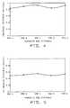
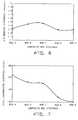
- Figs. 4-7illustrate stiffnesses of five different composite fixation rods in the torsional, medial/lateral bending, anterior/posterior bending and axial compression directions.
- Each of the fixation rodsis a hexagonal rod having dimensions of 12.57 ⁇ 0.13 mm (0.495 ⁇ 0.005 inch) across the flats and 14.66 mm (0.577 inch) from corner to corner.
- the following tablesset forth the number of laminae making up each rod illustrated in Figs. 4-7, the type of material for each lamina, the moment of inertia (I) for each lamina and the orientation of the fibers within each lamina relative to the longitudinal axis of the rod:
- the fiberglass listed in the above tables for fixation rods A-Eis an E fiberglass; the carbon has a tensile modulus of about 220 GPa (32 x 10 6 PSI); and the polyester has a tensile strength of about 9.7 GPa (1.4 x 10 6 PSI).
- the data illustrated in Figs. 4-6was obtained by attaching the five different fixation rods set forth immediately above to a simulated bone using a plurality of clamp assemblies and fixation pins as described above.
- the label "M/L Bending Stiffness” in Fig. 5indicates the medial/lateral bending stiffness of the fixation rods; and the label “A/P Bending Stiffness” in Fig. 6 indicates the anterior/posterior bending stiffness of the fixation rod.
- the medial/lateral bending stiffnessgenerally corresponds to a direction lying in a plane containing both the simulated bone and the fixation rod.
- the stiffness in the torsional, medial/lateral bending and anterior/posterior bending directionsdoes not vary significantly from one composite rod to another.
- the percentage change for the torsional stiffness and bending stiffness of the composite rodsis relatively small when calculated as a percentage change.
- axial compression stiffnessvaries much more dramatically than the torsional and bending stiffnesses. It is thus possible with the present invention to provide a plurality of fixation rods having the same exterior geometry and which include substantially constant torsional and bending stiffnesses while varying the axial compression stiffness.
- a fixation rod of the present inventionhaving a modulus of elasticity of between about 14-138 GPa (2-20 x 10 6 PSI). Bone has a modulus of elasticity of about 14 GPa (2 x 10 6 PSI) and titanium has a modulus of elasticity of about 110 GPa (16 x 10 6 PSI). It is therefore possible with the present invention to select a fixation rod having an axial compression stiffness ranging from that of bone to that of titanium. By providing a more adaptable fixation rod and eliminating the need to adjust the position of the fixation pins relative to the fixation rod, an increased predictability and improved healing process occurs.
Landscapes
- Health & Medical Sciences (AREA)
- Orthopedic Medicine & Surgery (AREA)
- Life Sciences & Earth Sciences (AREA)
- Surgery (AREA)
- Biomedical Technology (AREA)
- Engineering & Computer Science (AREA)
- Nuclear Medicine, Radiotherapy & Molecular Imaging (AREA)
- Heart & Thoracic Surgery (AREA)
- Medical Informatics (AREA)
- Molecular Biology (AREA)
- Animal Behavior & Ethology (AREA)
- General Health & Medical Sciences (AREA)
- Public Health (AREA)
- Veterinary Medicine (AREA)
- Surgical Instruments (AREA)
Description
- The present invention relates to an apparatus forexternal fixation and stabilization of a fractured bone, and,more particularly, to such an apparatus having a fixation rodinterconnected to the fractured bone at a plurality oflocations via a plurality of respective fixation pins.
- External fixation apparatus of known design are utilizedfor fixating and stabilizing fractured bones. While fixationapparatus and systems have undergone considerable evolutionarychanges over the years, they all rigidly hold the sections ofa broken bone in alignment throughout the healing process.Fixation devices may be in the form of a relatively crudesplint or cast, or a more modern and sophisticated systeminvolving surgical fixation pins secured to an externalfixation rod, or the Ilizarov system well known to thoseskilled in the art.
- Conventional fixation systems currently on the market mayinclude a hexagonal fixation bar used to interconnect andrigidly secure a plurality of fixation pins inserted into thefractured bone at various points, with each fixation pin beingretained within a clamp secured to the fixation rod. Eachclamp is installed onto the fixation rod by sliding the clamp over one end or the other and tightening one or more nuts whenthe clamp is in its desired longitudinal position on the rod.An example of such a system is disclosed in U.S. PatentApplication Serial No. 08/017,933, entitled "EXTERNAL FIXATIONAPPARATUS", filed February 16, 1993, and published as US 5 443 464 afterthe priority date of the present application.
- A problem with conventional designs is that they areconstructed of a metal having a known modulus of elasticity.The modulus of elasticity does not change for a particularmetal, regardless of whether the selected metal is acommercially pure or alloy material. For example, stainlesssteel has a modulus of elasticity of about 207 GPa (30 x 106 PSI);commercially pure titanium and titanium alloy have a modulusof elasticity of about 110 GPa (16 x 106 PSI); aluminum has a modulus ofelasticity of about 69 GPa (10 x 106 PSI); and magnesium has a modulusof elasticity of about 55-62 GPa (8 - 9 x 10⁶ PSI). The modulus ofelasticity in the axial direction of the fixation rod relatesto the amount of elastic movement possible within the fixationrod in an axial direction for a given axial load. Movement ofthe fixation rod in the axial direction, in turn, relates tothe amount of axial movement at the fracture site of the bone.It is generally accepted in the art that an increased axialmovement at the fracture site theoretically improves thefracture healing process. However, for a material such asstainless steel having a high modulus of elasticity, the loadsexperienced at the fracture site are not sufficient toelastically deform the fixation bar. Accordingly, no movement of the bone in an axial direction at the fracture site occurs,with resultant detrimental effects on the healing process.
- One known method of increasing the load on the bone atthe fracture site is to loosen the clamp assemblies attachedto the fixation rod and slide the clamp assemblies in an axialdirection along the fixation rod in a direction toward thefracture site. However, this results in a constant load beingplaced on the bone at the fracture site rather than inducingaxial movement of the bone sections on each side of thefracture site, since the fixation rod does not elasticallymove under such typical loads. EP-A-99 289 discloses a two part fixation rod in which the parts are connected by an elastic block. A compression load is placed on the fracture by the restoring force of the elastic block.
- Another problem is that the step between each respectivemodulus of elasticity for conventional fixation barsconstructed of different metals is quite large. For example,the step between the modulus of elasticity for stainless steeland titanium is about 97 GPa (14 x 106 PSI) (30 - 16). Since stainlesssteel and titanium are the two most commonly used materialsfor conventional fixation rods, the modulus of elasticity iseither 207 GPa (30 x 106 PSI) or 110 GPa (16 x 106 PSI), without the ability toselect a material having a modulus of elasticity disposedtherebetween.
- A still further problem is that clamp assemblies ofconventional design are made to accept a fixation rod of aparticular exterior geometric configuration. When a fixationrod constructed of one metal is substituted for a fixation rodconstructed of another metal, the exterior geometry mustremain the same in order to attach to the clamp assemblies. However, as the axial compression stiffness of the fixationrod changes as a result of the change in the modulus ofelasticity, the bending stiffness and torsional stiffness alsochange as a result of using a different material. Therefore,using a metal which has a lower modulus of elasticity toimprove the axial loading on the bone may result in otherdetrimental affects such as twisting or bending of thefixation rod, thereby allowing movement of the bone sectionsin a radial direction at the fracture site.
- What is needed in the art is an external fixationapparatus which includes a plurality of fixation rods havingan axial compression stiffness which may be varied, whilemaintaining a relatively constant torsional and bendingstiffness.
- The invention comprises, in one form thereof, anapparatus for external fixation and stabilization of afracture in a bone, including a fixation rod, atleast two fixation pins attachable to the bone, and at leasttwo clamp assemblies, each clamp assembly interconnecting atleast one fixation pin and the fixation rod, characterised in that said fixation rod is a one-piece element which iscompressible in an axial direction upon occurrence of axial loads typical to those experienced at the fracture, therebyallowing an axial compression loading to be placed on the boneat the fracture when the apparatus is in use.
- The apparatus may comprise,a fixationrod comprising an elongated rod having a substantiallyconstant cross-section and consisting essentially of a non-homogeneousmaterial.
- An advantage of the present invention is that a pluralityof rods are provided which have respective axial compressionstiffnesses.
- Another advantage is that the axial compression stiffnessvaries from rod to rod while the torsional and bendingstiffnesses remain relatively the same from rod to rod.
- Yet another advantage is that the fixation rod of thepresent invention is lightweight in comparison withconventional designs.
- A further advantage is that a plurality of fixation rodshaving respective predetermined axial compression stiffnessesare utilized, thereby allowing selective axial loads to beplaced on the bone at the fracture site, dependent on theparticular fixation rod utilized.
- A still further advantage is that the axial compressionstiffness of a particular fixation rod may be modified bychanging the internal, non-homogeneous construction thereof.
- An additional advantage is that the fixation rods of thepresent invention are X-ray and MRI radiolucent.
- Another advantage is that the exterior geometry of thefixation rods is the same as a conventional design, therebyallowing use with conventional clamp assemblies.
- The above-mentioned and other features and advantages ofthis invention, and the manner of attaining them, will becomemore apparent and the invention will be better understood byreference to the following description of an embodiment of theinvention taken in conjunction with the accompanying drawings,wherein:
- Fig. 1 is a perspective view of one embodiment of theexternal fixator assembly of the present invention, whenfastened to a fractured bone;
- Fig. 2 is a layered side view of the fixation rod shownin Fig. 1;
- Fig. 3 is a sectional view taken along line 3-3 of Fig.2;
- Fig. 4 is a graph illustrating the torsional stiffness offive different embodiments of the composite fixation rod ofthe present invention;
- Fig. 5 is a graph illustrating the medial/lateral bendingstiffness of the five different composite rods labeled in Fig.4;
- Fig. 6 is a graph illustrating the anterior/posteriorbending stiffness of the five different composite rods labeledin Fig. 4; and
- Fig. 7 is a graph illustrating the axial compressionstiffness of the five different composite rods labeled in Fig.4.
- Corresponding reference characters indicate correspondingparts throughout the several views. The exemplification setout herein illustrates one preferred embodiment of theinvention, in one form, and such exemplification is not to beconstrued as limiting the scope of the invention in anymanner.
- Referring now to the drawings and more particularly toFig. 1, there is shown an
external fixator assembly 10 whichis used to fixate and stabilizefracture 12 ofbone 14.External fixator assembly 10 includes ahexagonal fixation rod 16, to be described in more detail hereinafter, which isdisposed generally parallel withbone 14.Fixation pins 18include respective threadedends 20 which are screwed intobone 14 at desired locations. A plurality ofclamp assemblies 22 respectively interconnect at least onefixation pin 18 withfixation rod 16. Eachclamp assembly 22 includes abody 24with at least one first opening 25 for receivingfixation rod 16, and at least one second opening for receivingfixation pin 18.Body 24 is adapted to threadingly receive aretaining nut 26 associated with afixation pin 18, and aretaining nut 28 associated withfixation rod 16. Each of retainingnuts collets 30 which lockclampassembly 22 tofixation pins 18 andfixation rods 16,respectively. - In the embodiment shown, the
lowermost clamp assembly 22has tworetaining nuts 26, but only engages onefixation pin 18. It is to be understood, however, that aclamp assembly 22having two retainingnuts 26 can engage more than onefixationpin 18 if desirable for a particular application. - Referring now to Figs. 2 and 3,
fixation rod 16 of thepresent invention is shown in greater detail.Fixation rod 16shown in Figs. 1-3 includes seven separate laminae boundtogether by a resin, which together form a solid fixation rod.Thefirst lamina 32 includes polyester fibers which areoriented at a zero degree angle relative to alongitudinalaxis 34 offixation rod 16. That is,polyester fibers 32 areoriented generally parallel tolongitudinal axis 34.Secondlamina 36 includes glass fibers which are oriented at a zerodegree angle relative tolongitudinal axis 34.Third lamina 38 includes polyester fibers oriented at a zero degree anglerelative tolongitudinal axis 34.Fourth lamina 40 includescarbon fibers which are woven together and oriented atrespective 45° angles relative tolongitudinal axis 34.Fifthlamina 42 includes glass fibers oriented at an 82° anglerelative tolongitudinal axis 34.Sixth lamina 44 includesglass fibers oriented at a zero degree angle relative tolongitudinal axis 34.Seventh lamina 46 includes polyester fibers oriented at an 82° angle relative tolongitudinal axis 34.Seventh lamina 46 andfifth lamina 42 are disposed atopposite angles relative tolongitudinal axis 34.Laminae longitudinal axis 34, as shown in Fig. 3. - The fixation rod described above with reference to Figs.2 and 3 includes seven laminae with the respective fiberorientations as indicated. The orientation of the fiberswithin each lamina making up the composite fixation roddetermine the torsional, bending, and axial compressionstiffness of the rod. By varying the angles of the fibers inone or more layers with respect to the longitudinal axis ofthe rod, it is possible to modify the stiffness of the rod ina particular desired direction. For example, in theembodiment shown,
fourth lamina 40 including woven carbonlayers disposed at a 45° angle relative tolongitudinal axis 34primarily control the torsional stiffness offixation rod 16.By varying the angle of the carbon fibers infourth lamina 40,or the angle of the fibers in other laminae, it is possible toaffect the torsional, bending and axial compressionstiffnesses offixation rod 16. - Figs. 4-7 illustrate stiffnesses of five differentcomposite fixation rods in the torsional, medial/lateralbending, anterior/posterior bending and axial compressiondirections. Each of the fixation rods is a hexagonal rodhaving dimensions of 12.57 ± 0.13 mm (0.495 ± 0.005 inch) across the flats and 14.66 mm(0.577 inch) from corner to corner. The following tables set forth the number of laminae making up each rod illustrated in Figs.4-7, the type of material for each lamina, the moment ofinertia (I) for each lamina and the orientation of the fiberswithin each lamina relative to the longitudinal axis of therod:
Rod A: Lamina No. Material I Orientation 1 Polyester 2.94E-5 0° 2 Fiberglass 4.39E-4 0° 3 Polyester 8.68E-4 0° 4 Carbon 8.19E-4 ± 45° 5 Fiberglass 2.01E-4 + 82° 6 Fiberglass 1.19E-3 0° 7 Polyester 2.05E-4 -82° Rod B: Lamina No. Material I Orientation 1 Polyester 5.49E-4 0° 2 Fiberglass 4.27E-4 0° 3 Polyester 3.58E-4 0° 4 Carbon 8.21E-4 ± 45° 5 Fiberglass 2.01E-4 + 82° 6 Fiberglass 1.19E-3 0° 7 Polyester 2.06E-4 -82° Rod C (Hollow with plugged ends; I.D. = 8.25 mm, i.e. 0.325 inch): Lamina No. Material I Orientation 1 Fiberglass 4.38E-4 ± 45° 2 Carbon 7.15E-4 ± 45° 3 Fiberglass 1.58E-4 + 82° 4 Fiberglass 1.69E-3 0° 5 Polyester 2.05E-4 -82° Rod D (Hollow with plugged ends): Lamina No. Material I Orientation 1 Fiberglass 3.68E-4 ± 70° 2 Carbon 8.09E-4 ± 45° 3 Fiberglass 1.98E-4 + 82° 4 Fiberglass 1.25E-3 0° 5 Polyester 2.05E-4 - 82° Rod E (Hollow with plugged ends): Lamina No. Material I Orientation 1 Fiberglass 3.76E-4 ± 70° 2 Carbon 8.21E-4 ± 45° 3 Fiberglass 2.01E-4 + 82° 4 Fiberglass 1.19E-3 0° 5 Fiberglass 2.06E-4 - 82° - The data illustrated in Figs. 4-6 was obtained byattaching the five different fixation rods set forthimmediately above to a simulated bone using a plurality ofclamp assemblies and fixation pins as described above. Thelabel "M/L Bending Stiffness" in Fig. 5 indicates themedial/lateral bending stiffness of the fixation rods; and thelabel "A/P Bending Stiffness" in Fig. 6 indicates theanterior/posterior bending stiffness of the fixation rod. Themedial/lateral bending stiffness generally corresponds to adirection lying in a plane containing both the simulated boneand the fixation rod.
- As indicated by Figs. 4-6, the stiffness in thetorsional, medial/lateral bending and anterior/posteriorbending directions does not vary significantly from onecomposite rod to another. For each of the composite rods A -E shown in Figs. 4-6, the percentage change for the torsionalstiffness and bending stiffness of the composite rods isrelatively small when calculated as a percentage change.
- Referring now to Fig. 7, it is apparent that the axialcompression stiffness varies much more dramatically than thetorsional and bending stiffnesses. It is thus possible withthe present invention to provide a plurality of fixation rodshaving the same exterior geometry and which includesubstantially constant torsional and bending stiffnesses whilevarying the axial compression stiffness.
- Using a composite structure, it is possible to constructa fixation rod of the present invention having a modulus ofelasticity of between about 14-138 GPa (2-20
x 106 PSI). Bone has a modulusof elasticity of about 14 GPa (2 x 10⁶ PSI) and titanium has a modulusof elasticity of about 110 GPa (16 x 106 PSI). It is therefore possiblewith the present invention to select a fixation rod having anaxial compression stiffness ranging from that of bone to thatof titanium. By providing a more adaptable fixation rod andeliminating the need to adjust the position of the fixationpins relative to the fixation rod, an increased predictabilityand improved healing process occurs. - While this invention has been described as having apreferred design, the present invention can be furthermodified within the scope of the appendedclaims.
Claims (10)
- An apparatus for external fixation and stabilization of a fracture (12) in a bone (14),comprising:characterised in that said fixation rod (16) is a one-piece element which is compressiblein an axial direction upon occurrence of axial loads typical to those experienced at the fracture,thereby allowing an axial compression loading to be placed on the bone (14) at the fracture (12)when said apparatus is in use.a fixation rod (16);at least two fixation pins (18) attachable to the bone (14); andat least two clamp assemblies (22), each said clamp assembly (22) interconnecting at leastone said fixation pin (18) and said fixation rod (16);
- The apparatus of Claim 1, characterised in that said fixation rod (16) consistsessentially of a non-metallic composite material.
- The apparatus of Claim 2, characterised in that said composite material includesa plurality of layers, each said layer positioned concentrically about a longitudinal axis of saidfixation rod (16).
- The apparatus of Claim 3, characterised in that each said layer includes a pluralityof fibres having at least one defined orientation relative to said longitudinal axis.
- The apparatus as claimed in any preceding claim characterised in that it furthercomprises additional fixation rods (16), each said fixation rod (16) having a substantiallyidentical exterior geometry;wherein said fixation rods (16) have about the same bending and torsional stiffness fromone said fixation rod (16) to another, and have a varying axial compressing stiffness from onesaid fixation rod (16) to another.at least two fixation pins (18) attachable to the bone (14); andat least two clamp assemblies (22), each said clamp assembly (22) interconnecting at leastone said fixation pin (18) and a selected one of said fixation rods (16);
- The apparatus of Claim 5, characterised in that each said fixation rod (16) consistsessentially of a non-metallic composite material.
- The apparatus of Claim 6, characterised in that said composite material includesa plurality of layers, each said layer positioned concentrically about a longitudinal axis of saidfixation rod.
- The apparatus of Claim 7, characterised in that each said layer includes a pluralityof fibres having at least one defined orientation relative to said longitudinal axis.
- The apparatus of Claim 5, characterised in that the varying axial compressionstiffness from one said fixation rod (16) to another is of a uniform stepped increment.
- The apparatus of Claim 5, characterised in that each said fixation rod (16) isessentially radiolucent.
Applications Claiming Priority (2)
| Application Number | Priority Date | Filing Date | Title |
|---|---|---|---|
| US08/361,779US5591164A (en) | 1994-12-22 | 1994-12-22 | External fixation apparatus and system |
| US361779 | 1994-12-22 |
Publications (3)
| Publication Number | Publication Date |
|---|---|
| EP0717968A2 EP0717968A2 (en) | 1996-06-26 |
| EP0717968A3 EP0717968A3 (en) | 1996-11-20 |
| EP0717968B1true EP0717968B1 (en) | 2000-05-17 |
Family
ID=23423415
Family Applications (1)
| Application Number | Title | Priority Date | Filing Date |
|---|---|---|---|
| EP95203540AExpired - LifetimeEP0717968B1 (en) | 1994-12-22 | 1995-12-18 | External fixation apparatus and system |
Country Status (5)
| Country | Link |
|---|---|
| US (1) | US5591164A (en) |
| EP (1) | EP0717968B1 (en) |
| AU (1) | AU680782B2 (en) |
| CA (1) | CA2165365C (en) |
| DE (1) | DE69516989T2 (en) |
Cited By (1)
| Publication number | Priority date | Publication date | Assignee | Title |
|---|---|---|---|---|
| EP4475397A1 (en)* | 2023-06-07 | 2024-12-11 | Robert Bosch GmbH | Brushless electric machine and method for manufacturing brushless electric machine |
Families Citing this family (48)
| Publication number | Priority date | Publication date | Assignee | Title |
|---|---|---|---|---|
| US5252496A (en) | 1989-12-18 | 1993-10-12 | Princeton Biomeditech Corporation | Carbon black immunochemical label |
| IT1289103B1 (en)* | 1996-05-15 | 1998-09-25 | Orthofix Srl | COMPACT EXTERNAL FIXER |
| DE29619711U1 (en) | 1996-11-13 | 1998-03-12 | Synthes AG Chur, Chur, Graubünden | Device for repositioning bone fracture fragments |
| US6159210A (en)* | 1997-01-14 | 2000-12-12 | Research Corporation Technologies, Inc. | Bone fixation pin with rotary cutting tip |
| IT1298413B1 (en)* | 1997-05-21 | 2000-01-05 | Orthofix Srl | EXTERNAL MINIFIXER DEVICE FOR SMALL BONE TREATMENT |
| ATE334629T1 (en) | 1998-05-19 | 2006-08-15 | Synthes Ag | CONNECTING ELEMENT FOR MONOLATERAL EXTERNAL FIXATION SYSTEM FOR TRAUMATOLOGY AND ORTHOPEDIC |
| US6678562B1 (en) | 2000-01-12 | 2004-01-13 | Amei Technologies Inc. | Combined tissue/bone growth stimulator and external fixation device |
| US6423061B1 (en) | 2000-03-14 | 2002-07-23 | Amei Technologies Inc. | High tibial osteotomy method and apparatus |
| EP1522267B1 (en)* | 2003-10-06 | 2009-01-14 | Stryker Trauma SA | External fixation elements |
| EP1522266A1 (en)* | 2003-10-06 | 2005-04-13 | Stryker Trauma SA | External fixation elements |
| US20060229605A1 (en)* | 2005-03-18 | 2006-10-12 | Olsen Ron A | Adjustable splint for osteosynthesis with incrementing assembly for adjustment in predetermined increments |
| US7575575B2 (en)* | 2005-03-18 | 2009-08-18 | Ron Anthon Olsen | Adjustable splint for osteosynthesis with modular components |
| US8758343B2 (en)* | 2005-04-27 | 2014-06-24 | DePuy Synthes Products, LLC | Bone fixation apparatus |
| US8034078B2 (en) | 2008-05-30 | 2011-10-11 | Globus Medical, Inc. | System and method for replacement of spinal motion segment |
| US7731738B2 (en)* | 2005-12-09 | 2010-06-08 | Orthopro, Llc | Cannulated screw |
| GB0607535D0 (en)* | 2006-04-13 | 2006-05-24 | Fixator Innovations Ltd | Fixator member |
| US20070270821A1 (en)* | 2006-04-28 | 2007-11-22 | Sdgi Holdings, Inc. | Vertebral stabilizer |
| US7766942B2 (en)* | 2006-08-31 | 2010-08-03 | Warsaw Orthopedic, Inc. | Polymer rods for spinal applications |
| US7875059B2 (en)* | 2007-01-18 | 2011-01-25 | Warsaw Orthopedic, Inc. | Variable stiffness support members |
| US8740944B2 (en)* | 2007-02-28 | 2014-06-03 | Warsaw Orthopedic, Inc. | Vertebral stabilizer |
| WO2008134703A2 (en) | 2007-04-30 | 2008-11-06 | Globus Medical, Inc. | Flexible spine stabilization system |
| US9924969B2 (en) | 2012-09-04 | 2018-03-27 | Zimmer, Inc. | External fixation |
| US9301782B2 (en) | 2012-09-04 | 2016-04-05 | Zimmer, Inc. | External fixation |
| US9962188B2 (en) | 2013-10-29 | 2018-05-08 | Cardinal Health 247. Inc. | External fixation system and methods of use |
| US10314618B2 (en)* | 2014-07-25 | 2019-06-11 | The General Hospital Corporation | System and method for an external hip fixator |
| US9962187B2 (en) | 2014-08-11 | 2018-05-08 | Zimmer, Inc. | External fixation |
| WO2016205128A2 (en) | 2015-06-17 | 2016-12-22 | Nathan Erickson | Ankle fixation system |
| US9872707B2 (en) | 2015-12-03 | 2018-01-23 | Globus Medical, Inc. | External fixator assembly |
| US10682160B2 (en) | 2015-12-03 | 2020-06-16 | Globus Medical, Inc. | External fixator assembly |
| US10136919B2 (en) | 2015-12-03 | 2018-11-27 | Globus Medical, Inc. | External fixator assembly |
| US9943337B2 (en) | 2015-12-03 | 2018-04-17 | Globus Medical, Inc. | External fixator assembly |
| US11331069B2 (en) | 2016-01-11 | 2022-05-17 | Kambiz Behzadi | Invasive sense measurement in prosthesis installation |
| US11241248B2 (en) | 2016-01-11 | 2022-02-08 | Kambiz Behzadi | Bone preparation apparatus and method |
| US10251663B2 (en) | 2016-01-11 | 2019-04-09 | Kambiz Behzadi | Bone preparation apparatus and method |
| US11399946B2 (en) | 2016-01-11 | 2022-08-02 | Kambiz Behzadi | Prosthesis installation and assembly |
| US11534314B2 (en) | 2016-01-11 | 2022-12-27 | Kambiz Behzadi | Quantitative assessment of prosthesis press-fit fixation |
| US11291426B2 (en) | 2016-01-11 | 2022-04-05 | Kambiz Behzadi | Quantitative assessment of implant bone preparation |
| US11109802B2 (en) | 2016-01-11 | 2021-09-07 | Kambiz Behzadi | Invasive sense measurement in prosthesis installation and bone preparation |
| US11234840B2 (en) | 2016-01-11 | 2022-02-01 | Kambiz Behzadi | Bone preparation apparatus and method |
| US12193951B2 (en) | 2016-01-11 | 2025-01-14 | Kambiz Behzadi | Quantitative assessment of prosthesis press-fit fixation |
| US11375975B2 (en) | 2016-01-11 | 2022-07-05 | Kambiz Behzadi | Quantitative assessment of implant installation |
| US11751807B2 (en) | 2016-01-11 | 2023-09-12 | Kambiz Behzadi | Invasive sense measurement in prosthesis installation and bone preparation |
| US11458028B2 (en) | 2016-01-11 | 2022-10-04 | Kambiz Behzadi | Prosthesis installation and assembly |
| US11298102B2 (en) | 2016-01-11 | 2022-04-12 | Kambiz Behzadi | Quantitative assessment of prosthesis press-fit fixation |
| US10864083B2 (en) | 2016-04-07 | 2020-12-15 | Kambiz Behzadi | Mechanical assembly including exterior surface preparation |
| US11406504B2 (en) | 2016-06-12 | 2022-08-09 | Kambiz Behzadi | Mechanical assembly including exterior surface preparation |
| US11013545B2 (en) | 2018-05-30 | 2021-05-25 | Acumed Llc | Distraction/compression apparatus and method for bone |
| US11969336B2 (en) | 2018-10-08 | 2024-04-30 | Kambiz Behzadi | Connective tissue grafting |
Family Cites Families (33)
| Publication number | Priority date | Publication date | Assignee | Title |
|---|---|---|---|---|
| US1793393A (en) | 1928-10-30 | 1931-02-17 | Glaenzer Harry | End frame of locomotives |
| DE2745504A1 (en)* | 1977-10-10 | 1979-04-19 | Erich Strickle | DEVICE FOR RESTING OR SUPPORTING LIMBS OF PEOPLE AND ANIMALS |
| CH630798A5 (en)* | 1979-01-16 | 1982-07-15 | Jaquet Orthopedie | EXTERNAL FIXER FOR OSTEOSYNTHESIS. |
| US4308863A (en)* | 1979-10-18 | 1982-01-05 | Ace Orthopedic Manufacturing, Inc. | External fixation device |
| GB2104782B (en)* | 1981-08-06 | 1984-11-28 | Nat Res Dev | Fracture fixator |
| FR2529778B1 (en)* | 1982-07-09 | 1985-10-25 | Paris Ecole Nale Sup Arts Meti | FIXING DEVICE FOR IMMOBILIZING LONG BONES WITH OPEN FRACTURE |
| US4889111A (en)* | 1984-02-08 | 1989-12-26 | Ben Dov Meir | Bone growth stimulator |
| US4747400A (en)* | 1984-04-26 | 1988-05-31 | Harrington Arthritis Research Center | External fixation device |
| US4895141A (en)* | 1984-04-26 | 1990-01-23 | Harrington Arthritis Research Center | Unilateral external fixation device |
| US4584995A (en)* | 1984-04-26 | 1986-04-29 | Orthotic Limited Partnership | External fixation device |
| US4624249A (en)* | 1984-12-04 | 1986-11-25 | Medicuba | Orthopedic external fixing apparatus |
| CH664079A5 (en)* | 1985-01-24 | 1988-02-15 | Jaquet Orthopedie | BOW ELEMENT AND EXTERNAL FIXER FOR OSTEOSYNTHESIS AND OSTEOPLASTY. |
| US4620533A (en)* | 1985-09-16 | 1986-11-04 | Pfizer Hospital Products Group Inc. | External bone fixation apparatus |
| IL80661A (en)* | 1985-11-29 | 1991-07-18 | Jaquet Orthopedie | Device for positioning and securing a part having circular regions |
| FR2595045B1 (en)* | 1986-02-28 | 1991-12-27 | Hardy Jean Marie | DEVICE FOR IMMOBILIZING A BONE ELEMENT, PARTICULARLY FOR ORTHOPEDIC INTERVENTION |
| US4978360A (en)* | 1986-03-03 | 1990-12-18 | Zimmer, Inc. | Method of manufacturing a composite implant prosthesis |
| US4902297A (en)* | 1986-03-03 | 1990-02-20 | Zimmer, Inc. | Composite implant prosthesis |
| US4923458A (en)* | 1986-04-17 | 1990-05-08 | Ace Medical Company | Surgical fixation pin tension adjuster |
| DE3628972A1 (en)* | 1986-08-26 | 1988-03-03 | Herzberg Wolfgang | AEUSSERER FASTENER FOR THE STABILIZATION OF CERTAIN BONE BREAKS IN HUMAN AND ANIMAL |
| US5192330A (en)* | 1987-01-20 | 1993-03-09 | Smith & Nephew Richards, Inc. | Orthopedic device of biocompatible polymer with oriented fiber reinforcement |
| DE3720242A1 (en)* | 1987-06-19 | 1988-12-29 | Schewior Thomas Dr Med | RING FIXATEUR FOR SETTING UP BONE SECTIONS AND / OR FRAGMENTS AND FOR GENERATING BONE TENSIONS |
| US5219363A (en)* | 1988-03-22 | 1993-06-15 | Zimmer, Inc. | Bone implant |
| WO1990000882A1 (en)* | 1988-07-25 | 1990-02-08 | Vsesojuzny Kurgansky Nauchny Tsentr 'vosstanovitelnaya Travmatologia I Ortopedia' | Traction apparatus for restoring the shape of the hand |
| US4978358A (en)* | 1988-10-06 | 1990-12-18 | Zimmer Inc. | Orthopaedic prosthetic device possessing improved composite stem design |
| US4936843A (en)* | 1989-02-16 | 1990-06-26 | Ace Orthopedic Manufacturing | Kirschner wire clamp and tensioner |
| IT1228812B (en)* | 1989-03-22 | 1991-07-04 | Ortomedical S R L | EXTRAFOCAL FIXING EQUIPMENT FOR TRANSOXIC SYNTHESIS OF DISTRACTIONS AND COMPRESSIONS IN ORTHOPEDICS AND TRAUMATOLOGY. |
| US5112331A (en)* | 1989-06-15 | 1992-05-12 | Vel Miletich | Orthopedic pins for external fixator |
| CH681352A5 (en)* | 1989-09-27 | 1993-03-15 | Jaquet Orthopedie | |
| US5163962A (en)* | 1990-08-30 | 1992-11-17 | Bhc Laboratories, Inc. | Composite femoral implant having increased neck strength |
| FR2667781B1 (en)* | 1990-10-12 | 1994-01-21 | Materiel Orthopedique Cie Gle | EXTERNAL FIXATION AND REDUCTION OF BONE FRACTURES. |
| US5181930A (en)* | 1991-04-10 | 1993-01-26 | Pfizer Hospital Products Group, Inc. | Composite orthopedic implant |
| US5275598A (en)* | 1991-10-09 | 1994-01-04 | Cook Richard L | Quasi-isotropic apparatus and method of fabricating the apparatus |
| US5350378A (en)* | 1993-05-19 | 1994-09-27 | Cole J Dean | Posterior external pelvic fixator |
- 1994
- 1994-12-22USUS08/361,779patent/US5591164A/ennot_activeExpired - Lifetime
- 1995
- 1995-11-20AUAU37936/95Apatent/AU680782B2/ennot_activeCeased
- 1995-12-15CACA002165365Apatent/CA2165365C/ennot_activeExpired - Fee Related
- 1995-12-18DEDE69516989Tpatent/DE69516989T2/ennot_activeExpired - Fee Related
- 1995-12-18EPEP95203540Apatent/EP0717968B1/ennot_activeExpired - Lifetime
Cited By (1)
| Publication number | Priority date | Publication date | Assignee | Title |
|---|---|---|---|---|
| EP4475397A1 (en)* | 2023-06-07 | 2024-12-11 | Robert Bosch GmbH | Brushless electric machine and method for manufacturing brushless electric machine |
Also Published As
| Publication number | Publication date |
|---|---|
| US5591164A (en) | 1997-01-07 |
| CA2165365A1 (en) | 1996-06-23 |
| CA2165365C (en) | 2006-05-23 |
| EP0717968A2 (en) | 1996-06-26 |
| DE69516989D1 (en) | 2000-06-21 |
| EP0717968A3 (en) | 1996-11-20 |
| DE69516989T2 (en) | 2000-10-05 |
| AU680782B2 (en) | 1997-08-07 |
| AU3793695A (en) | 1996-06-27 |
Similar Documents
| Publication | Publication Date | Title |
|---|---|---|
| EP0717968B1 (en) | External fixation apparatus and system | |
| US5330474A (en) | Vertebral locking and retrieving system | |
| US5891144A (en) | External fixator | |
| US5257994A (en) | Vertebral locking and retrieving system | |
| EP1972289B1 (en) | Elongated stabilization member and bone anchor useful in bone and especially spinal repair processes | |
| US5196014A (en) | Vertebral locking and retrieving system | |
| AU680209B2 (en) | Spinal rod transverse connector for supporting vertebral fixation elements | |
| US6712820B2 (en) | Fixation plate system for dorsal wrist fracture fixation | |
| DE10348329B3 (en) | Rod-shaped element used in spinal column and accident surgery for connecting two bone-anchoring elements comprises a rigid section and an elastic section that are made in one piece | |
| US4978348A (en) | Compression-distraction apparatus for osteosynthesis | |
| US6645207B2 (en) | Method and apparatus for dynamized spinal stabilization | |
| KR0128893B1 (en) | Variable Angle Bone Screw System | |
| US5217461A (en) | Apparatus for maintaining vertebrae in a desired spatial relationship | |
| US3977397A (en) | Surgical compression-distraction instrument | |
| US6508819B1 (en) | Method of dorsal wrist fracture fixation | |
| WO1994002078A1 (en) | External axial fixator for osteosynthesis | |
| EP0313556B1 (en) | External fixation device | |
| CA2123353A1 (en) | Composite spinal apparatus | |
| CN1575152A (en) | System for fixation of fractures comprising an elastic chassis | |
| EP1337192A1 (en) | Set of surgical instruments for the fixation of vertebrae | |
| EP0458486A1 (en) | Bone fixator | |
| RU1771717C (en) | Device for spinal column stabilization | |
| WO2003020007A2 (en) | Method and apparatus for dorsal wrist fracture fixation | |
| Kleining | External fixation: Biomechanical considerations and analysis of components | |
| CZ216194A3 (en) | Apparatus for fixing spinal bones |
Legal Events
| Date | Code | Title | Description |
|---|---|---|---|
| PUAI | Public reference made under article 153(3) epc to a published international application that has entered the european phase | Free format text:ORIGINAL CODE: 0009012 | |
| AK | Designated contracting states | Kind code of ref document:A2 Designated state(s):DE FR GB | |
| PUAL | Search report despatched | Free format text:ORIGINAL CODE: 0009013 | |
| AK | Designated contracting states | Kind code of ref document:A3 Designated state(s):DE FR GB | |
| 17P | Request for examination filed | Effective date:19970520 | |
| 17Q | First examination report despatched | Effective date:19980713 | |
| GRAG | Despatch of communication of intention to grant | Free format text:ORIGINAL CODE: EPIDOS AGRA | |
| GRAG | Despatch of communication of intention to grant | Free format text:ORIGINAL CODE: EPIDOS AGRA | |
| GRAH | Despatch of communication of intention to grant a patent | Free format text:ORIGINAL CODE: EPIDOS IGRA | |
| GRAG | Despatch of communication of intention to grant | Free format text:ORIGINAL CODE: EPIDOS AGRA | |
| GRAH | Despatch of communication of intention to grant a patent | Free format text:ORIGINAL CODE: EPIDOS IGRA | |
| GRAA | (expected) grant | Free format text:ORIGINAL CODE: 0009210 | |
| AK | Designated contracting states | Kind code of ref document:B1 Designated state(s):DE FR GB | |
| REF | Corresponds to: | Ref document number:69516989 Country of ref document:DE Date of ref document:20000621 | |
| ET | Fr: translation filed | ||
| PGFP | Annual fee paid to national office [announced via postgrant information from national office to epo] | Ref country code:DE Payment date:20001211 Year of fee payment:6 | |
| PLBE | No opposition filed within time limit | Free format text:ORIGINAL CODE: 0009261 | |
| STAA | Information on the status of an ep patent application or granted ep patent | Free format text:STATUS: NO OPPOSITION FILED WITHIN TIME LIMIT | |
| 26N | No opposition filed | ||
| REG | Reference to a national code | Ref country code:GB Ref legal event code:IF02 | |
| PG25 | Lapsed in a contracting state [announced via postgrant information from national office to epo] | Ref country code:DE Free format text:LAPSE BECAUSE OF NON-PAYMENT OF DUE FEES Effective date:20020702 | |
| PGFP | Annual fee paid to national office [announced via postgrant information from national office to epo] | Ref country code:FR Payment date:20041217 Year of fee payment:10 | |
| PG25 | Lapsed in a contracting state [announced via postgrant information from national office to epo] | Ref country code:FR Free format text:LAPSE BECAUSE OF NON-PAYMENT OF DUE FEES Effective date:20060831 | |
| REG | Reference to a national code | Ref country code:FR Ref legal event code:ST Effective date:20060831 | |
| REG | Reference to a national code | Ref country code:GB Ref legal event code:732E | |
| PGFP | Annual fee paid to national office [announced via postgrant information from national office to epo] | Ref country code:GB Payment date:20081229 Year of fee payment:14 | |
| GBPC | Gb: european patent ceased through non-payment of renewal fee | Effective date:20091218 | |
| PG25 | Lapsed in a contracting state [announced via postgrant information from national office to epo] | Ref country code:GB Free format text:LAPSE BECAUSE OF NON-PAYMENT OF DUE FEES Effective date:20091218 |