EP0717862B1 - Optical fibre organizer - Google Patents
Optical fibre organizerDownload PDFInfo
- Publication number
- EP0717862B1 EP0717862B1EP94925536AEP94925536AEP0717862B1EP 0717862 B1EP0717862 B1EP 0717862B1EP 94925536 AEP94925536 AEP 94925536AEP 94925536 AEP94925536 AEP 94925536AEP 0717862 B1EP0717862 B1EP 0717862B1
- Authority
- EP
- European Patent Office
- Prior art keywords
- ports
- organiser
- fibres
- fibre
- port
- Prior art date
- Legal status (The legal status is an assumption and is not a legal conclusion. Google has not performed a legal analysis and makes no representation as to the accuracy of the status listed.)
- Expired - Lifetime
Links
- 239000013307optical fiberSubstances0.000titleclaimsabstractdescription38
- 239000000835fiberSubstances0.000claimsabstractdescription51
- 230000003287optical effectEffects0.000claimsdescription9
- 238000009434installationMethods0.000description2
- 239000000463materialSubstances0.000description2
- 230000000717retained effectEffects0.000description2
- 230000003044adaptive effectEffects0.000description1
- 238000005452bendingMethods0.000description1
- 238000004891communicationMethods0.000description1
- 238000010276constructionMethods0.000description1
- 230000007613environmental effectEffects0.000description1
- 238000003780insertionMethods0.000description1
- 230000037431insertionEffects0.000description1
- 230000014759maintenance of locationEffects0.000description1
- 239000004033plasticSubstances0.000description1
- 229920003023plasticPolymers0.000description1
- 230000000750progressive effectEffects0.000description1
Images


Classifications
- G—PHYSICS
- G02—OPTICS
- G02B—OPTICAL ELEMENTS, SYSTEMS OR APPARATUS
- G02B6/00—Light guides; Structural details of arrangements comprising light guides and other optical elements, e.g. couplings
- G02B6/24—Coupling light guides
- G—PHYSICS
- G02—OPTICS
- G02B—OPTICAL ELEMENTS, SYSTEMS OR APPARATUS
- G02B6/00—Light guides; Structural details of arrangements comprising light guides and other optical elements, e.g. couplings
- G02B6/44—Mechanical structures for providing tensile strength and external protection for fibres, e.g. optical transmission cables
- G02B6/4439—Auxiliary devices
- G02B6/4471—Terminating devices ; Cable clamps
- G02B6/4476—Terminating devices ; Cable clamps with heat-shrinkable elements
- G—PHYSICS
- G02—OPTICS
- G02B—OPTICAL ELEMENTS, SYSTEMS OR APPARATUS
- G02B6/00—Light guides; Structural details of arrangements comprising light guides and other optical elements, e.g. couplings
- G02B6/44—Mechanical structures for providing tensile strength and external protection for fibres, e.g. optical transmission cables
- G02B6/4439—Auxiliary devices
- G02B6/444—Systems or boxes with surplus lengths
- G02B6/4453—Cassettes
- G02B6/4454—Cassettes with splices
Definitions
- the present inventionrelates to an optical fibre organizer for use in an optical fibre network.
- Optical fibresare in general very small, brittle and therefore easily damaged and as a result great care must be taken in their installation and use.
- a fibreIn order to avoid damage and light loss, a fibre must not be bent excessively and it must not be subject to unfavourable environmental conditions.
- each fibrehas a so-called critical bend radius below which light will be lost from the fibre. Therefore, an optical fibre system must be so configured that none of its fibres is bent at a bend radius below this critical value. Also, fibres must not be even temporarily bent during installation below a smaller bend radius at which permanent damage will occur.
- the components in an optical fibre systemare required to organize cables and their component optical fibres at, for example, cable terminations, cable splices and fibre splitters. This involves careful fibre routing, for example to allow easy access to each of many fibre splices, and storage of spare lengths of fibre.
- US 4840449discloses an optical fibre organizer and splicing arrangement that permits storage of variable lengths of surplus fibre.
- the organizerhas a pair of separated cylinders extending from a first rectangular section of a base plate and a splice tray having opposite entrance sides for optical fibre in a second rectangular section.
- the surplus fibreis directed around one or both cylinders and underneath the splicing tray through a plurality of different length passageways so that the varying lengths of optical fibre are stored. Clockwise, counter-clockwise and figure 8 loops are used so that each optical fibre end is directed to a predetermined entrance side of the splicing tray without violating the fibre bend radius restriction.
- US 4627686discloses a splicing tray for optical fibres and optical fibre cables comprising three elements: a base, a number of optical fibre storage means associated with the base, and an optical fibre receiving means attached to the base.
- a baseAround the periphery of the base is a plurality of upstanding sidewall members, the terminal portion of which is curved inwardly towards the centre of the base.
- WO 91/10927discloses an adaptive racking and distribution flame system for handling optical fibre cables. It includes racking sections with wall portions that can be replaced without removing the section or displacing cables in the section, and further includes housings with moveable shelves that can be adapted to hold optical fibre splices, optical fibre connectors, or optical fibre spools.
- WO901 12334discloses an optical fibre organiser according to the pre-characterising portion of the attached claim 1.
- the present inventionprovides an optical fibre organizer according to the present claim 1.
- the drum 5be substantially cylindrical, preferably of substantially circular cross-section. They may, however, vary in size or shape along its length. For example they may be waisted in order to locate fibre at some position along its length. More than two drums may be provided in order to give greater flexibility to the lengths of fibre that can be stored. Two drums allow fibre to be wrapped either around one drum only, around both drums without cross-over, or around both drums in a figure of eight configuration.
- the drumsneed not be made of sheet material and may instead comprise a frame : references to the shape of the drums refer to their envelope, as would be followed by a fibre wrapped around them.
- the outlet portbe provided at an opposite edge portion of the organizer to the inlet ports, in particular, we prefer that two outlet ports be provided one at each side of the organizer at an edge portion of the organizer opposite to that of the inlet ports.
- the inlet portsare preferably arranged in a row extending across the width of the organizer from one side to the other.
- the two drumsare preferably provided, side-by-side, between the row of inlet ports and the two outlet ports.
- the number of inlet ports in the rowwill depend on the fibre network, but we prefer that there be at least four, more preferably at least 8, preferably from 20 to 60 for example about 36.
- the several bend control meanspreferably comprise substantially mutually concentric curved walls, which may be substantially continuous along their length, but may instead comprise a series of posts etc. These curved walls are provided in two groups those at one side of the organizer being curved towards that side and those at the other side of the organizer being curved towards that side of the organizer. This arrangement will be particularly preferred when the organizer has reflectional symmetry about a plane between two organizer drums.
- the device defined aboveusefully organizes fibres leaving one or more cables before those fibres are directed to splicing or splitting trays.
- the organizeris preferably of unitary construction and may conveniently be moulded from a suitable plastics material.
- Figure 1shows a prior art optical fibre organizer as disclosed in US 4840449 (AT&T).
- An optical fibre cable 1 containing optical fibres 2is secured to an optical fibre organizer by means of a cable tying post 3.
- the fibrespass through an inlet port 4 and are stored around drums 5 protruding from a face 6.
- the optical fibrespass under a splicing tray 7 where a splice between them is secured. It may be noted that there is no means for individually organizing a plurality of incoming cables or fibres, there is no way of dealing with dark fibre, and only cables entering in the plane of the face 6 can be dealt with.
- a prior art optical fibre organizer disclosed in US 4627686(Siecor) is shown in figure 2.
- incoming cables 1are arranged side-by-side and the fibres 2 they contain are simply routed around the base of the organizer and are retained by its side walls. The cables are held in place by a clamp 3.
- a fibre receiving means 7comprises a series of slots which can retain fibre splices for connection to the outgoing cable shown at the top left of the figure.
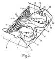
- Figure 3shows an optical fibre organizer having a first face partially bound by first (top-left as drawn) and second (lower right as drawn) opposite edge portions, a first face:
- the drums 14, 15are preferably such that a fibre passing between any of the walls 16, 17 and the outlet ports 10, 11 is constrained by an outer surface of one or both drums 13, 14 to a minimum bend radius at least equal to the critical bend radius of the fibre, the drums 13, 14 preferably being hollow allowing a free end of fibre to pass from one of the ports, generally one of the inlet ports 8, 9, to the interior of the drums.
- the fibreswill be stored in the drums at a minimum bend radius greater than that at which they suffer permanent damage. This minimum bend radius may be larger than the critical bend radius of the fibre since it is permanent damage rather than light loss that is of concern in the case of the dark fibre.
- the through port 12extends from a convex portion 18 of the face of the organizer at an angle to its radius vector at that portion (i.e. not radially and preferably close to tangentially) such that a fibre extending through the port 12 and over convex surface 18 is constrained to a minimum bend radius at least equal to its critical bend radius.
- the organizerpreferably has side walls or other retaining means 19 and the drums preferably have hooks or other retaining means 20 that help guide the fibres.
- FIGS. 4A to 4EFurther views of the organizer can be seen in figures 4A to 4E.
- FIG 4Afor example it can be seen that walls 12A of the through port 12 curve along a path towards the drums 13, 14. This curvature may result from a progressive broadening of the cross-sectional size of the through port 12 towards the face illustrated in figure 4A.
- the through port 12includes a substantially straight passage from one face to the opposite face allowing easy insertion of optical fibres. This can be seen best, perhaps, in figure 4B. It can be seen therefore that a fibre passing through the through hole 12 towards the drums 13, 14 is constrained to a given minimum bend radius.
- the drums 13, 14can be seen, particularly from figure 3, to be hollow thus allowing a free end of fibre to pass from one of the ports to the interior of the drums where it can be stored.
- the hollow drumshave slots 15 in their walls through which such fibre can pass.
- the inlet ports 8, 9can be seen to have bend control means in the form of substantially mutually concentric curved walls 16, 17.
- the organizer shownhas reflective symmetry about line AA and as a result the bend control means are arranged in two groups 16, 17, where the walls curve in opposite directions.
- Figures 5A to Eshow the flexibility of the organizer in accommodating various configurations and lengths of fibre.
- fibreenters the organizer from through hole 12 and leaves through outlets 10 and 11. Also, some dark fibre leaves through hole 12 and is stored in drum 13.
- the organizerhere is intended to be used with other components such as optical fibre splice trays accommodating fibre splices and/or fibre splitters.
- the organizerwill be aligned with a base plate carrying such trays, on the right-hand side of which there may be a channel for accommodating fibres entering the splice trays, and on the left-hand side of which there may be a channel accommodating fibres leaving the splice trays.
- These passagesmay be referred to arbitrarily as an in trench and an out trench, although this is not intended to imply any direction of light travel.
- fibresenter through inlet ports 8 and leave through outlet port 10, and enter through inlet ports 9 and leave through outlet port 11.
- fibresenter through inlet ports 8 and leave through outlet port 11.
- An optical fibre break-out device 34is shown in figures 6A to E It may be removably secured into, for example, the slots comprising the inlet ports 8, 9 of the organizer of figure 3. This can be done by means of a resilient detent 35, 56 comprising for example the two legs illustrated, one of which 36 is barbed to engage a lower surface of the wall defining the slot.
- the break-out device 34can be seen to have a first passage 37 for retaining a larger fibre tube (shown dotted at the upper right-hand side) and four second passage 39 (at the lower left hand end as drawn). for retaining a plurality of smaller fibre tubes. Fibres in such tubes can be seen to be able to pass between the larger tube and each smaller tube without bending that would cause significant light loss.
- the four second passages 39comprise a single passage partially sub-divided by inwardly extending protrusions 40 for retention of the tubes therein.
- the precise shape of such protrusions 40is not critical, but in a preferred embodiment the protrusions result from the second passages 39 having a cross-section substantially that of a plurality of partially overlapping circles In this way, the tubes are retained by interference fit.
- four second passages 39are shown, other numbers for example from 2-6 may be provided.
- FIG. 7shows an organizer 21 as described above sealed within a splice closure, shown in cut-away to expose the organizer 21.
- the splice closurecomprises a base 22 and a dome-shaped cover 23.
- the base 22carries various circular ports 24 and an oval port 25.
- Attached to the baseis a frame or other support 26 to which the organizer 21 is attached.
- a second support or frame 27is provided separated from frame or support 26 by a gap 28. This gap 28 may contain loops of fibre from incoming and outgoing cables that are not spliced within the enclosure and therefore by-pass organizer 21.
- a second organizer 21may be provided on the back of the frame or support 27, and therefore out of view. The two organizers may then be in communication via their through holes 12.
- Organizer traysmay be provided in space 29 carrying fibre splices and/or fibre splitters.
- cables entering the port 25may be split such that some of the fibres they contain enter the organizer 21 as illustrated in figures 5A to 5E, and may leave organizer 21 to splice trays positioned in space 29.
- the fibreswill be spliced or split and the fibres to which they are spliced or into which they are split may re-enter the organizer 21 and finally leave it, again as shown in figures 5A to 5E.
- Other fibres from the incoming cablemay be looped in space 28 and then exit through the port. In general this will be done by taking a loop of cable of approximately two metres length which loop is inserted into oval port 25.
- That loop of cablemay form part of a ring or spur in a fibre optic network.
- the fibres leaving circular ports 24 after being spliced to the cut fibres of that loopmay pass to subscribers or may be used to form a further spur.
- Figure 8illustrates optical fibre trays that may be positioned in space 29 or otherwise used in conjunction with organizer 21.
- the module 30 illustrated in figure 8, which may be preinstalled with fibres,comprises a series of trays 31 hinged to a mounting device 32 which is in turn fixed to a base 33.
- the trays 31can be seen to have means for storing loops of fibres and for securing fibre splices or fibre splitters.
- This modulemay be snap-fitted or otherwise attached at space 29 of figure 7 and the fibres it contains then spliced to those leaving the organizer 21.
Landscapes
- Physics & Mathematics (AREA)
- General Physics & Mathematics (AREA)
- Optics & Photonics (AREA)
- Light Guides In General And Applications Therefor (AREA)
- Glass Compositions (AREA)
- Mechanical Coupling Of Light Guides (AREA)
- Optical Couplings Of Light Guides (AREA)
- Optical Communication System (AREA)
- Optical Fibers, Optical Fiber Cores, And Optical Fiber Bundles (AREA)
- Laser Surgery Devices (AREA)
- Surface Treatment Of Glass Fibres Or Filaments (AREA)
- Manufacture, Treatment Of Glass Fibers (AREA)
- Developing Agents For Electrophotography (AREA)
- Golf Clubs (AREA)
- Paper (AREA)
- Yarns And Mechanical Finishing Of Yarns Or Ropes (AREA)
- Preliminary Treatment Of Fibers (AREA)
Abstract
Description
Claims (8)
- An optical fibre organiser (21) comprising a substantially planar support base,having:(i) a plurality of first ports (8,9) spaced along one edge of the planar support base through which optical fibres can pass to or from the organiser;(ii) a second port (10, 11) through which optical fibres can pass to or from theorganiser;(iii) optical fibre storage means in the form of two drums (13, 14) with an outersurface positioned such as to provide a path for fibres passing from the first ports (8,9) to the second port (10, 11) with a minimum bend radius at least equal to the criticalbend radius of the fibres;(iv) a plurality of bend control means (16, 17) located between the saidfirst ports (8, 9) and the said two drums comprising the optical fibre storage means(13, 14) to direct fibrespassing through the first ports towards the outer curved surface of a respective drum(13, 14) at a minimum bend radius at least equal to the critical bend radius of that fibre;the bend control means comprising a plurality of curved walls definingbetween them part of the said curved paths between the respective first port and arespective drum,
characterised in that the said first portsare separeted into two groups by a line passing between the said two drums,andin that bend control means curvein opposite directions from one another and away from the said line todefine paths for optical fibres from one group of first ports to a first of the two drums and from theother group of first ports to the otherof the two drums. - An organiser according to Claim 1,characterised in that the second port (10,11) is at an opposite edge portion thereof to the said plurality of first ports (8, 9).
- An organiser according to Claim 1 or Claim 2,characterised in that there areat least four said first ports (8, 9) arranged in a row along an edge portion thereof.
- An organiser according to any preceding claim,characterised in that the saidcurved walls comprising the bend control means (16, 17) are substantially mutuallyconcentric.
- An organiser according to any preceding claim,characterised in that there areat least two second ports (10, 11) and at least two drums (13, 14), the organiser beingsubstantially symmetrical about a plane passing between the two drums.
- An organiser according to any preceding claim,characterised in that the or eachorganiser drum (13, 14) is hollow and has an opening (15) allowing a free end of anoptical fibre to pass from a said inlet port (8, 9) or said outlet port (10, 11) to theinterior of the drum and to be stored therein at a minimum bend radius greater thanthat at which it suffers permanent damage.
- An organiser according to any preceding claim,characterised in that theorganiser additionally comprises a third port (12) that extends through the planarsupport base of the organiser to an opposite face thereof, on which planar support basethe said first ports (8, 9), the or each second port (10, 11), and the or each drum (13, 14) are located.
- An organiser according to any preceding claim,characterised in that each firstport has an optical fibre termination or break-out device which is provided withsecuring means by which it may be removably secured to the associated first part, thebreak-out device having a first passage for retaining a large fibre tube and one or moresecond passages for retaining a plurality of smaller fibre tubes or fibres such that fibrescan pass between the large tube and each smaller tube without significant light loss.
Applications Claiming Priority (3)
| Application Number | Priority Date | Filing Date | Title |
|---|---|---|---|
| GB9318602 | 1993-09-08 | ||
| GB939318602AGB9318602D0 (en) | 1993-09-08 | 1993-09-08 | Optical fibre organizer |
| PCT/GB1994/001909WO1995007482A1 (en) | 1993-09-08 | 1994-09-02 | Optical fibre organizer |
Publications (2)
| Publication Number | Publication Date |
|---|---|
| EP0717862A1 EP0717862A1 (en) | 1996-06-26 |
| EP0717862B1true EP0717862B1 (en) | 2001-11-14 |
Family
ID=10741690
Family Applications (1)
| Application Number | Title | Priority Date | Filing Date |
|---|---|---|---|
| EP94925536AExpired - LifetimeEP0717862B1 (en) | 1993-09-08 | 1994-09-02 | Optical fibre organizer |
Country Status (27)
| Country | Link |
|---|---|
| US (1) | US5764843A (en) |
| EP (1) | EP0717862B1 (en) |
| JP (1) | JPH09502281A (en) |
| KR (1) | KR100326643B1 (en) |
| CN (1) | CN1059502C (en) |
| AT (1) | ATE208908T1 (en) |
| AU (1) | AU698186B2 (en) |
| BR (1) | BR9407430A (en) |
| CA (1) | CA2171001C (en) |
| CZ (1) | CZ288254B6 (en) |
| DE (1) | DE69429097T2 (en) |
| DK (1) | DK0717862T3 (en) |
| ES (1) | ES2164106T3 (en) |
| FI (1) | FI115672B (en) |
| GB (1) | GB9318602D0 (en) |
| HU (1) | HU218817B (en) |
| IL (1) | IL110869A (en) |
| IN (1) | IN184935B (en) |
| MY (1) | MY114247A (en) |
| NO (1) | NO316552B1 (en) |
| PL (1) | PL174664B1 (en) |
| RO (1) | RO117574B1 (en) |
| RU (1) | RU2131613C1 (en) |
| SK (1) | SK283865B6 (en) |
| TW (1) | TW295738B (en) |
| WO (1) | WO1995007482A1 (en) |
| ZA (1) | ZA946915B (en) |
Families Citing this family (52)
| Publication number | Priority date | Publication date | Assignee | Title |
|---|---|---|---|---|
| GB2292466B (en)* | 1994-08-15 | 1997-09-10 | Pirelli General Plc | Guiding optical fibres in ducts |
| US5647045A (en)* | 1996-02-23 | 1997-07-08 | Leviton Manufacturing Co., Inc. | Multi-media connection housing |
| TW364953B (en)* | 1997-04-15 | 1999-07-21 | Rxs Schrumpftech Garnituren | Cable closure having a holding device for cassettes for depositing and splicing optical fibres |
| US5987203A (en)* | 1997-10-09 | 1999-11-16 | Lucent Technologies Inc. | Distribution module for optical couplings |
| IT1308599B1 (en)* | 1999-02-11 | 2002-01-08 | Minnesota Mining Mfg Italia | LIMITED ENVIRONMENT SHEET FOR HOUSING OF JOINTS FOR FIBER TAPES FIBER OPTIC CABLES FOR TELECOMMUNICATIONS |
| SE517302C2 (en)* | 1999-05-27 | 2002-05-21 | Ericsson Telefon Ab L M | Apparatus for delimiting and separating optical fibers in an isolated space |
| DE19956067A1 (en)* | 1999-11-22 | 2001-05-23 | Rxs Kabelgarnituren Gmbh & Co | Cassette for accommodating optical fibres, surplus lengths, splices, etc., has differently shaped splice holders for various types of splice protection elements, and add-on elements for adapting to required use |
| GB2367378B (en)* | 2000-09-27 | 2004-08-25 | Krone Gmbh | Patch panel |
| GB0108255D0 (en)* | 2001-04-02 | 2001-05-23 | Tyco Electronics Raychem Nv | Optical fibre organiser |
| DE60109429T2 (en) | 2001-06-08 | 2006-05-11 | Pirelli General Plc | Arrangement for connections between optical fibers |
| EP1267192B1 (en)* | 2001-06-15 | 2009-02-18 | Prysmian Cables & Systems Limited | Connecting optical fibres |
| US6744962B2 (en) | 2001-10-25 | 2004-06-01 | Uniseal, Inc. | Fiberoptic splice closure |
| US7027706B2 (en)* | 2003-12-23 | 2006-04-11 | Hewlett-Packard Development Company, L.P. | Systems, apparatuses, and methods for managing cables with minimum bend radius |
| CA2558996A1 (en)* | 2004-03-08 | 2005-09-22 | Adc Telecommunications, Inc. | Fiber access terminal |
| US7489849B2 (en) | 2004-11-03 | 2009-02-10 | Adc Telecommunications, Inc. | Fiber drop terminal |
| CA2642812A1 (en)* | 2006-02-22 | 2007-08-30 | Prysmian Cables & Systems Limited | A routing device for optical fibre systems |
| EP2084563A1 (en)* | 2006-11-16 | 2009-08-05 | Prysmian Cables & Systems UK Ltd | Splicing box |
| US7822310B2 (en)* | 2007-02-28 | 2010-10-26 | Corning Cable Systems Llc | Fiber optic splice trays |
| US7558458B2 (en) | 2007-03-08 | 2009-07-07 | Adc Telecommunications, Inc. | Universal bracket for mounting a drop terminal |
| US7512304B2 (en)* | 2007-03-23 | 2009-03-31 | Adc Telecommunications, Inc. | Drop terminal with anchor block for retaining a stub cable |
| US20090046985A1 (en)* | 2007-08-16 | 2009-02-19 | Erik Gronvall | Fiber Optic Enclosure Internal Cable Management |
| US8798427B2 (en) | 2007-09-05 | 2014-08-05 | Corning Cable Systems Llc | Fiber optic terminal assembly |
| EP2198328B1 (en) | 2007-10-09 | 2018-09-26 | ADC Telecommunications, INC. | Mini drop terminal |
| US7903923B2 (en)* | 2007-10-09 | 2011-03-08 | Adc Telecommunications, Inc. | Drop terminal releasable engagement mechanism |
| CN102209921B (en) | 2008-10-09 | 2015-11-25 | 康宁光缆系统有限公司 | There is the fibre-optic terminus supported from the adapter panel of the input and output optical fiber of optical splitters |
| US8879882B2 (en) | 2008-10-27 | 2014-11-04 | Corning Cable Systems Llc | Variably configurable and modular local convergence point |
| ES2425950T3 (en) | 2009-02-10 | 2013-10-18 | Tyco Electronics Raychem Bvba | Housing for a fiber optic assembly |
| EP2237091A1 (en) | 2009-03-31 | 2010-10-06 | Corning Cable Systems LLC | Removably mountable fiber optic terminal |
| US8467651B2 (en) | 2009-09-30 | 2013-06-18 | Ccs Technology Inc. | Fiber optic terminals configured to dispose a fiber optic connection panel(s) within an optical fiber perimeter and related methods |
| US9547144B2 (en) | 2010-03-16 | 2017-01-17 | Corning Optical Communications LLC | Fiber optic distribution network for multiple dwelling units |
| US8792767B2 (en) | 2010-04-16 | 2014-07-29 | Ccs Technology, Inc. | Distribution device |
| WO2012054454A2 (en) | 2010-10-19 | 2012-04-26 | Corning Cable Systems Llc | Transition box for multiple dwelling unit fiber optic distribution network |
| IT1402878B1 (en)* | 2010-11-19 | 2013-09-27 | Prysmian Spa | OPTICAL TRANSITION BOX |
| IT1404383B1 (en)* | 2011-02-24 | 2013-11-22 | Prysmian Spa | DEVICE TO ACCOMMODATE TREATMENTS OF OPTICAL FIBERS. |
| US9219546B2 (en) | 2011-12-12 | 2015-12-22 | Corning Optical Communications LLC | Extremely high frequency (EHF) distributed antenna systems, and related components and methods |
| US10110307B2 (en) | 2012-03-02 | 2018-10-23 | Corning Optical Communications LLC | Optical network units (ONUs) for high bandwidth connectivity, and related components and methods |
| US9791653B2 (en) | 2012-04-03 | 2017-10-17 | CommScope Connectivity Belgium BVBA | Telecommunications enclosure organizer |
| US9004778B2 (en) | 2012-06-29 | 2015-04-14 | Corning Cable Systems Llc | Indexable optical fiber connectors and optical fiber connector arrays |
| US9049500B2 (en) | 2012-08-31 | 2015-06-02 | Corning Cable Systems Llc | Fiber optic terminals, systems, and methods for network service management |
| PL2717081T3 (en)* | 2012-10-02 | 2021-05-31 | Corning Research & Development Corporation | Distribution housing for optical fibers |
| US8909019B2 (en) | 2012-10-11 | 2014-12-09 | Ccs Technology, Inc. | System comprising a plurality of distribution devices and distribution device |
| US12402946B2 (en) | 2019-06-19 | 2025-09-02 | Boston Scientific Scimed, Inc. | Breakdown of laser pulse energy for breakup of vascular calcium |
| US12280223B2 (en) | 2019-06-26 | 2025-04-22 | Boston Scientific Scimed, Inc. | Focusing element for plasma system to disrupt vascular lesions |
| US12102384B2 (en) | 2019-11-13 | 2024-10-01 | Bolt Medical, Inc. | Dynamic intravascular lithotripsy device with movable energy guide |
| US12274497B2 (en) | 2019-12-18 | 2025-04-15 | Bolt Medical, Inc. | Multiplexer for laser-driven intravascular lithotripsy device |
| US12295654B2 (en) | 2020-06-03 | 2025-05-13 | Boston Scientific Scimed, Inc. | System and method for maintaining balloon integrity within intravascular lithotripsy device with plasma generator |
| US12016610B2 (en) | 2020-12-11 | 2024-06-25 | Bolt Medical, Inc. | Catheter system for valvuloplasty procedure |
| EP4277548B1 (en) | 2021-01-12 | 2025-06-04 | Bolt Medical, Inc. | Balloon assembly for valvuloplasty catheter system |
| US11839391B2 (en) | 2021-12-14 | 2023-12-12 | Bolt Medical, Inc. | Optical emitter housing assembly for intravascular lithotripsy device |
| JP1721877S (en)* | 2022-01-31 | 2022-08-08 | Optical fiber storage tray | |
| JP1721876S (en)* | 2022-01-31 | 2022-08-08 | Optical fiber storage tray | |
| WO2024026322A1 (en)* | 2022-07-26 | 2024-02-01 | Bolt Medical, Inc. | Routing assembly for intravascular lithotripsy catheter system |
Family Cites Families (18)
| Publication number | Priority date | Publication date | Assignee | Title |
|---|---|---|---|---|
| JPS60196704A (en)* | 1984-03-21 | 1985-10-05 | Furukawa Electric Co Ltd:The | Extra optical fiber length storage case |
| US4627686A (en)* | 1984-08-10 | 1986-12-09 | Siecor Corporation | Splicing tray for optical fibers |
| FR2573544B1 (en)* | 1984-11-20 | 1987-04-24 | Mars Actel | OPTICAL FIBER CONNECTION SUPPORT |
| FR2577688B1 (en)* | 1985-02-21 | 1989-04-28 | Lignes Telegraph Telephon | OPTICAL FIBER DISTRIBUTOR |
| DE3706768A1 (en)* | 1987-03-03 | 1988-09-15 | Philips Patentverwaltung | RECEIVING DEVICE FOR THE STOCK LENGTH OF AT LEAST ONE LIGHT WAVE GUIDE |
| US4840449A (en)* | 1988-01-27 | 1989-06-20 | American Telephone And Telegraph Company, At&T Bell Laboratories | Optical fiber splice organizer |
| JPH063487B2 (en)* | 1988-03-15 | 1994-01-12 | 住友電気工業株式会社 | Multi-fiber optical fiber cable junction box |
| GB8908399D0 (en)* | 1989-04-13 | 1989-06-01 | British Telecomm | Optical fibre back plane |
| GB8912767D0 (en)* | 1989-06-02 | 1989-07-19 | British Telecomm | Splice organiser |
| US5013121A (en)* | 1989-06-29 | 1991-05-07 | Anton Mark A | Optical fiber storage container |
| SU1688217A1 (en)* | 1989-08-14 | 1991-10-30 | Центральный научно-исследовательский институт судовой электротехники и технологии | The fiber optic cable junction box |
| FR2656114B1 (en)* | 1989-12-19 | 1992-02-28 | Mars Actel | OPTICAL FIBER STORAGE DEVICE, PARTICULARLY FOR BREWING BOX. |
| US5100221A (en)* | 1990-01-22 | 1992-03-31 | Porta Systems Corp. | Optical fiber cable distribution frame and support |
| DE4030310A1 (en)* | 1990-09-25 | 1992-03-26 | Siemens Ag | DISTRIBUTION RACK FOR LIGHT GUIDE |
| DE4106171A1 (en)* | 1991-02-27 | 1992-09-03 | Siemens Ag | CASSETTE AND CASSETTE BLOCK FOR LIGHTWAVE GUIDE |
| NZ243203A (en)* | 1991-06-18 | 1995-12-21 | British Telecomm | Termination unit for optical fibre cable stores splices and fibre lengths |
| US5167001A (en)* | 1991-09-03 | 1992-11-24 | Northern Telecom Limited | Optical fiber storage and connector tray and shelf and tray assembly |
| DE4235208A1 (en)* | 1992-10-20 | 1994-04-21 | Sel Alcatel Ag | Frame with inserts for guiding fiber optic cables |
- 1993
- 1993-09-08GBGB939318602Apatent/GB9318602D0/enactivePending
- 1994
- 1994-09-02CNCN94193839Apatent/CN1059502C/ennot_activeExpired - Fee Related
- 1994-09-02HUHU9600546Apatent/HU218817B/ennot_activeIP Right Cessation
- 1994-09-02RORO96-00496Apatent/RO117574B1/enunknown
- 1994-09-02EPEP94925536Apatent/EP0717862B1/ennot_activeExpired - Lifetime
- 1994-09-02WOPCT/GB1994/001909patent/WO1995007482A1/enactiveIP Right Grant
- 1994-09-02SKSK288-96Apatent/SK283865B6/ennot_activeIP Right Cessation
- 1994-09-02AUAU75406/94Apatent/AU698186B2/ennot_activeCeased
- 1994-09-02CACA002171001Apatent/CA2171001C/ennot_activeExpired - Fee Related
- 1994-09-02USUS08/612,938patent/US5764843A/ennot_activeExpired - Lifetime
- 1994-09-02ATAT94925536Tpatent/ATE208908T1/enactive
- 1994-09-02CZCZ1996715Apatent/CZ288254B6/ennot_activeIP Right Cessation
- 1994-09-02ESES94925536Tpatent/ES2164106T3/ennot_activeExpired - Lifetime
- 1994-09-02DKDK94925536Tpatent/DK0717862T3/enactive
- 1994-09-02JPJP7508510Apatent/JPH09502281A/enactivePending
- 1994-09-02DEDE69429097Tpatent/DE69429097T2/ennot_activeExpired - Lifetime
- 1994-09-02KRKR1019960701118Apatent/KR100326643B1/ennot_activeExpired - Fee Related
- 1994-09-02BRBR9407430Apatent/BR9407430A/ennot_activeIP Right Cessation
- 1994-09-02PLPL94313324Apatent/PL174664B1/ennot_activeIP Right Cessation
- 1994-09-02RURU96107263Apatent/RU2131613C1/ennot_activeIP Right Cessation
- 1994-09-05ILIL11086994Apatent/IL110869A/ennot_activeIP Right Cessation
- 1994-09-07MYMYPI94002348Apatent/MY114247A/enunknown
- 1994-09-07ININ872MA1994patent/IN184935B/enunknown
- 1994-09-08TWTW083108298Apatent/TW295738B/zhnot_activeIP Right Cessation
- 1994-09-08ZAZA946915Apatent/ZA946915B/enunknown
- 1996
- 1996-03-07NONO960931Apatent/NO316552B1/ennot_activeIP Right Cessation
- 1996-03-07FIFI961060Apatent/FI115672B/ennot_activeIP Right Cessation
Also Published As
Similar Documents
| Publication | Publication Date | Title |
|---|---|---|
| EP0717862B1 (en) | Optical fibre organizer | |
| AU698822B2 (en) | Optical fibre organizer | |
| US5911027A (en) | Optical fibre organizer having through port extending between opposite faces thereof | |
| EP0692102B1 (en) | Optical fibre organizer | |
| EP0939914B1 (en) | Optical fibre organizer | |
| AU697942B2 (en) | Optical fibre organizer |
Legal Events
| Date | Code | Title | Description |
|---|---|---|---|
| PUAI | Public reference made under article 153(3) epc to a published international application that has entered the european phase | Free format text:ORIGINAL CODE: 0009012 | |
| 17P | Request for examination filed | Effective date:19960220 | |
| AK | Designated contracting states | Kind code of ref document:A1 Designated state(s):AT BE CH DE DK ES FR GB GR IE IT LI NL PT SE | |
| 17Q | First examination report despatched | Effective date:19971002 | |
| GRAG | Despatch of communication of intention to grant | Free format text:ORIGINAL CODE: EPIDOS AGRA | |
| GRAG | Despatch of communication of intention to grant | Free format text:ORIGINAL CODE: EPIDOS AGRA | |
| GRAG | Despatch of communication of intention to grant | Free format text:ORIGINAL CODE: EPIDOS AGRA | |
| GRAH | Despatch of communication of intention to grant a patent | Free format text:ORIGINAL CODE: EPIDOS IGRA | |
| RAP1 | Party data changed (applicant data changed or rights of an application transferred) | Owner name:TYCO ELECTRONICS RAYCHEM NV | |
| GRAH | Despatch of communication of intention to grant a patent | Free format text:ORIGINAL CODE: EPIDOS IGRA | |
| GRAA | (expected) grant | Free format text:ORIGINAL CODE: 0009210 | |
| AK | Designated contracting states | Kind code of ref document:B1 Designated state(s):AT BE CH DE DK ES FR GB GR IE IT LI NL PT SE | |
| PG25 | Lapsed in a contracting state [announced via postgrant information from national office to epo] | Ref country code:GR Free format text:LAPSE BECAUSE OF FAILURE TO SUBMIT A TRANSLATION OF THE DESCRIPTION OR TO PAY THE FEE WITHIN THE PRESCRIBED TIME-LIMIT Effective date:20011114 | |
| REF | Corresponds to: | Ref document number:208908 Country of ref document:AT Date of ref document:20011115 Kind code of ref document:T | |
| REG | Reference to a national code | Ref country code:CH Ref legal event code:NV Representative=s name:KIRKER & CIE SA Ref country code:CH Ref legal event code:EP | |
| REG | Reference to a national code | Ref country code:IE Ref legal event code:FG4D | |
| REF | Corresponds to: | Ref document number:69429097 Country of ref document:DE Date of ref document:20011220 | |
| REG | Reference to a national code | Ref country code:GB Ref legal event code:IF02 | |
| PG25 | Lapsed in a contracting state [announced via postgrant information from national office to epo] | Ref country code:SE Free format text:LAPSE BECAUSE OF FAILURE TO SUBMIT A TRANSLATION OF THE DESCRIPTION OR TO PAY THE FEE WITHIN THE PRESCRIBED TIME-LIMIT Effective date:20020214 Ref country code:PT Free format text:LAPSE BECAUSE OF FAILURE TO SUBMIT A TRANSLATION OF THE DESCRIPTION OR TO PAY THE FEE WITHIN THE PRESCRIBED TIME-LIMIT Effective date:20020214 | |
| REG | Reference to a national code | Ref country code:ES Ref legal event code:FG2A Ref document number:2164106 Country of ref document:ES Kind code of ref document:T3 | |
| ET | Fr: translation filed | ||
| REG | Reference to a national code | Ref country code:DK Ref legal event code:T3 | |
| PG25 | Lapsed in a contracting state [announced via postgrant information from national office to epo] | Ref country code:IE Free format text:LAPSE BECAUSE OF NON-PAYMENT OF DUE FEES Effective date:20020902 | |
| PLBE | No opposition filed within time limit | Free format text:ORIGINAL CODE: 0009261 | |
| STAA | Information on the status of an ep patent application or granted ep patent | Free format text:STATUS: NO OPPOSITION FILED WITHIN TIME LIMIT | |
| 26N | No opposition filed | ||
| REG | Reference to a national code | Ref country code:IE Ref legal event code:MM4A | |
| PGFP | Annual fee paid to national office [announced via postgrant information from national office to epo] | Ref country code:ES Payment date:20100927 Year of fee payment:17 Ref country code:CH Payment date:20100930 Year of fee payment:17 | |
| PGFP | Annual fee paid to national office [announced via postgrant information from national office to epo] | Ref country code:FR Payment date:20100930 Year of fee payment:17 Ref country code:AT Payment date:20100819 Year of fee payment:17 | |
| PGFP | Annual fee paid to national office [announced via postgrant information from national office to epo] | Ref country code:GB Payment date:20100927 Year of fee payment:17 | |
| PGFP | Annual fee paid to national office [announced via postgrant information from national office to epo] | Ref country code:NL Payment date:20100924 Year of fee payment:17 Ref country code:DK Payment date:20100928 Year of fee payment:17 | |
| PGFP | Annual fee paid to national office [announced via postgrant information from national office to epo] | Ref country code:DE Payment date:20100929 Year of fee payment:17 Ref country code:BE Payment date:20100927 Year of fee payment:17 | |
| PGFP | Annual fee paid to national office [announced via postgrant information from national office to epo] | Ref country code:IT Payment date:20100928 Year of fee payment:17 | |
| BERE | Be: lapsed | Owner name:*TYCO ELECTRONICS RAYCHEM N.V. Effective date:20110930 | |
| REG | Reference to a national code | Ref country code:NL Ref legal event code:V1 Effective date:20120401 | |
| REG | Reference to a national code | Ref country code:CH Ref legal event code:PL Ref country code:DK Ref legal event code:EBP | |
| GBPC | Gb: european patent ceased through non-payment of renewal fee | Effective date:20110902 | |
| PG25 | Lapsed in a contracting state [announced via postgrant information from national office to epo] | Ref country code:IT Free format text:LAPSE BECAUSE OF NON-PAYMENT OF DUE FEES Effective date:20110902 | |
| REG | Reference to a national code | Ref country code:FR Ref legal event code:ST Effective date:20120531 | |
| PG25 | Lapsed in a contracting state [announced via postgrant information from national office to epo] | Ref country code:BE Free format text:LAPSE BECAUSE OF NON-PAYMENT OF DUE FEES Effective date:20110930 | |
| REG | Reference to a national code | Ref country code:DE Ref legal event code:R119 Ref document number:69429097 Country of ref document:DE Effective date:20120403 | |
| PG25 | Lapsed in a contracting state [announced via postgrant information from national office to epo] | Ref country code:LI Free format text:LAPSE BECAUSE OF NON-PAYMENT OF DUE FEES Effective date:20110930 Ref country code:CH Free format text:LAPSE BECAUSE OF NON-PAYMENT OF DUE FEES Effective date:20110930 Ref country code:DE Free format text:LAPSE BECAUSE OF NON-PAYMENT OF DUE FEES Effective date:20120403 Ref country code:NL Free format text:LAPSE BECAUSE OF NON-PAYMENT OF DUE FEES Effective date:20120401 | |
| PG25 | Lapsed in a contracting state [announced via postgrant information from national office to epo] | Ref country code:FR Free format text:LAPSE BECAUSE OF NON-PAYMENT OF DUE FEES Effective date:20110930 Ref country code:GB Free format text:LAPSE BECAUSE OF NON-PAYMENT OF DUE FEES Effective date:20110902 | |
| PG25 | Lapsed in a contracting state [announced via postgrant information from national office to epo] | Ref country code:DK Free format text:LAPSE BECAUSE OF NON-PAYMENT OF DUE FEES Effective date:20110930 | |
| REG | Reference to a national code | Ref country code:AT Ref legal event code:MM01 Ref document number:208908 Country of ref document:AT Kind code of ref document:T Effective date:20110902 | |
| PG25 | Lapsed in a contracting state [announced via postgrant information from national office to epo] | Ref country code:AT Free format text:LAPSE BECAUSE OF NON-PAYMENT OF DUE FEES Effective date:20110902 | |
| REG | Reference to a national code | Ref country code:ES Ref legal event code:FD2A Effective date:20130604 | |
| PG25 | Lapsed in a contracting state [announced via postgrant information from national office to epo] | Ref country code:ES Free format text:LAPSE BECAUSE OF NON-PAYMENT OF DUE FEES Effective date:20110903 |