EP0715470B1 - System for supplying a plurality of ATM cells - Google Patents
System for supplying a plurality of ATM cellsDownload PDFInfo
- Publication number
- EP0715470B1 EP0715470B1EP19960101410EP96101410AEP0715470B1EP 0715470 B1EP0715470 B1EP 0715470B1EP 19960101410EP19960101410EP 19960101410EP 96101410 AEP96101410 AEP 96101410AEP 0715470 B1EP0715470 B1EP 0715470B1
- Authority
- EP
- European Patent Office
- Prior art keywords
- atm
- subscriber
- television
- atm cell
- subscribers
- Prior art date
- Legal status (The legal status is an assumption and is not a legal conclusion. Google has not performed a legal analysis and makes no representation as to the accuracy of the status listed.)
- Expired - Lifetime
Links
Images


Classifications
- H—ELECTRICITY
- H04—ELECTRIC COMMUNICATION TECHNIQUE
- H04N—PICTORIAL COMMUNICATION, e.g. TELEVISION
- H04N21/00—Selective content distribution, e.g. interactive television or video on demand [VOD]
- H04N21/20—Servers specifically adapted for the distribution of content, e.g. VOD servers; Operations thereof
- H04N21/23—Processing of content or additional data; Elementary server operations; Server middleware
- H04N21/236—Assembling of a multiplex stream, e.g. transport stream, by combining a video stream with other content or additional data, e.g. inserting a URL [Uniform Resource Locator] into a video stream, multiplexing software data into a video stream; Remultiplexing of multiplex streams; Insertion of stuffing bits into the multiplex stream, e.g. to obtain a constant bit-rate; Assembling of a packetised elementary stream
- H04N21/23608—Remultiplexing multiplex streams, e.g. involving modifying time stamps or remapping the packet identifiers
- H—ELECTRICITY
- H04—ELECTRIC COMMUNICATION TECHNIQUE
- H04L—TRANSMISSION OF DIGITAL INFORMATION, e.g. TELEGRAPHIC COMMUNICATION
- H04L49/00—Packet switching elements
- H04L49/30—Peripheral units, e.g. input or output ports
- H04L49/3081—ATM peripheral units, e.g. policing, insertion or extraction
- H—ELECTRICITY
- H04—ELECTRIC COMMUNICATION TECHNIQUE
- H04N—PICTORIAL COMMUNICATION, e.g. TELEVISION
- H04N21/00—Selective content distribution, e.g. interactive television or video on demand [VOD]
- H04N21/20—Servers specifically adapted for the distribution of content, e.g. VOD servers; Operations thereof
- H04N21/21—Server components or server architectures
- H04N21/222—Secondary servers, e.g. proxy server, cable television Head-end
- H04N21/2221—Secondary servers, e.g. proxy server, cable television Head-end being a cable television head-end
- H—ELECTRICITY
- H04—ELECTRIC COMMUNICATION TECHNIQUE
- H04N—PICTORIAL COMMUNICATION, e.g. TELEVISION
- H04N21/00—Selective content distribution, e.g. interactive television or video on demand [VOD]
- H04N21/60—Network structure or processes for video distribution between server and client or between remote clients; Control signalling between clients, server and network components; Transmission of management data between server and client, e.g. sending from server to client commands for recording incoming content stream; Communication details between server and client
- H04N21/63—Control signaling related to video distribution between client, server and network components; Network processes for video distribution between server and clients or between remote clients, e.g. transmitting basic layer and enhancement layers over different transmission paths, setting up a peer-to-peer communication via Internet between remote STB's; Communication protocols; Addressing
- H04N21/637—Control signals issued by the client directed to the server or network components
- H04N21/6373—Control signals issued by the client directed to the server or network components for rate control, e.g. request to the server to modify its transmission rate
- H—ELECTRICITY
- H04—ELECTRIC COMMUNICATION TECHNIQUE
- H04N—PICTORIAL COMMUNICATION, e.g. TELEVISION
- H04N21/00—Selective content distribution, e.g. interactive television or video on demand [VOD]
- H04N21/60—Network structure or processes for video distribution between server and client or between remote clients; Control signalling between clients, server and network components; Transmission of management data between server and client, e.g. sending from server to client commands for recording incoming content stream; Communication details between server and client
- H04N21/63—Control signaling related to video distribution between client, server and network components; Network processes for video distribution between server and clients or between remote clients, e.g. transmitting basic layer and enhancement layers over different transmission paths, setting up a peer-to-peer communication via Internet between remote STB's; Communication protocols; Addressing
- H04N21/643—Communication protocols
- H04N21/64307—ATM
- H—ELECTRICITY
- H04—ELECTRIC COMMUNICATION TECHNIQUE
- H04N—PICTORIAL COMMUNICATION, e.g. TELEVISION
- H04N7/00—Television systems
- H04N7/16—Analogue secrecy systems; Analogue subscription systems
- H04N7/173—Analogue secrecy systems; Analogue subscription systems with two-way working, e.g. subscriber sending a programme selection signal
- H04N7/17345—Control of the passage of the selected programme
- H04N7/17354—Control of the passage of the selected programme in an intermediate station common to a plurality of user terminals
- H—ELECTRICITY
- H04—ELECTRIC COMMUNICATION TECHNIQUE
- H04Q—SELECTING
- H04Q11/00—Selecting arrangements for multiplex systems
- H04Q11/04—Selecting arrangements for multiplex systems for time-division multiplexing
- H04Q11/0428—Integrated services digital network, i.e. systems for transmission of different types of digitised signals, e.g. speech, data, telecentral, television signals
- H04Q11/0478—Provisions for broadband connections
- H—ELECTRICITY
- H04—ELECTRIC COMMUNICATION TECHNIQUE
- H04L—TRANSMISSION OF DIGITAL INFORMATION, e.g. TELEGRAPHIC COMMUNICATION
- H04L12/00—Data switching networks
- H04L12/54—Store-and-forward switching systems
- H04L12/56—Packet switching systems
- H04L12/5601—Transfer mode dependent, e.g. ATM
- H04L2012/5603—Access techniques
- H04L2012/5609—Topology
- H04L2012/561—Star, e.g. cross-connect, concentrator, subscriber group equipment, remote electronics
- H—ELECTRICITY
- H04—ELECTRIC COMMUNICATION TECHNIQUE
- H04L—TRANSMISSION OF DIGITAL INFORMATION, e.g. TELEGRAPHIC COMMUNICATION
- H04L12/00—Data switching networks
- H04L12/54—Store-and-forward switching systems
- H04L12/56—Packet switching systems
- H04L12/5601—Transfer mode dependent, e.g. ATM
- H04L2012/5603—Access techniques
- H04L2012/5609—Topology
- H04L2012/5612—Ring
- H—ELECTRICITY
- H04—ELECTRIC COMMUNICATION TECHNIQUE
- H04L—TRANSMISSION OF DIGITAL INFORMATION, e.g. TELEGRAPHIC COMMUNICATION
- H04L12/00—Data switching networks
- H04L12/54—Store-and-forward switching systems
- H04L12/56—Packet switching systems
- H04L12/5601—Transfer mode dependent, e.g. ATM
- H04L2012/5614—User Network Interface
- H04L2012/5615—Network termination, e.g. NT1, NT2, PBX
- H—ELECTRICITY
- H04—ELECTRIC COMMUNICATION TECHNIQUE
- H04L—TRANSMISSION OF DIGITAL INFORMATION, e.g. TELEGRAPHIC COMMUNICATION
- H04L12/00—Data switching networks
- H04L12/54—Store-and-forward switching systems
- H04L12/56—Packet switching systems
- H04L12/5601—Transfer mode dependent, e.g. ATM
- H04L2012/5672—Multiplexing, e.g. coding, scrambling
Definitions
- the present inventiongenerally relates to a television signal and asynchronous transfer mode (ATM) cell switching system for accommodating television signals sent from a cable television head end (CATV-HE) into an ATM switching network, so as to provide a subscriber with both a television signal and ATM cell data other than the television signal.
- ATMasynchronous transfer mode
- the inventionrelates to a system for supplying a plurality of ATM cells corresponding to a plurality of channels to a plurality of subscribers.
- ATM cell switching systemsare described for example in EP-A-0 355 797 or EP-A-0 351 818.
- An object of the present inventionis to provide a system for supplying a plurality of ATM cells corresponding to a plurality of channels to a plurality of subscribers, capable of providing an ATM cell to a subscriber connected to an ATM switching network.
- a television signal and ATM switching systemfor switching channels of television signals from a source and ATM cells of data other than said television signals from a network and for supplying one of the channels of television signals and data other than the said television signals to each of subscribers, comprising a television signal switching unit, operatively connected to the source, for switching the channels of television signals to provide a plurality of television signal outputs directing to the subscribers respectively, an ATM switching unit for switching the ATM cells of data other than the television signals to provide ATM cells directed to the subscribers respectively, and a multiplexing unit, operatively connected to the output of the television signal switching unit and the ATM switching unit, for multiplexing each output of the television signal switching unit and each output of the ATM switching unit to provide a multiplexed television and data signal to one of the directed subscribers, whereby one-way communication of the television signals from the source to the subscribers and two-way communication of the data other than the television signals between the network and the subscribers are carried out.
- the television signal switching unitis a space-division type synchronous transfer mode switch for switching a plurality of channels of the television signals in accordance with requests from the subscribers.
- the sourcehas an ATM cell generating unit for generating ATM cells of the television signals.
- the television signal switching unit, the ATM switching unit, and the multiplexing unitconsist of a single ATM switch.
- a television signal and an ATM cell switching systemin an exchange apparatus for performing data switching of ATM cells and for supplying one channel among television signals of a plurality of channels transmitted from a source to a subscriber, comprising a television signal transmitting unit for transmitting television signals in the form of ATM cells, an ATM switching unit for switching ATM cell data other than the television signals, a television signal cell inserting circuit, operatively connected to the television signal transmitting unit and the ATM switching unit, for receiving a plurality of channels of television signals from the television signal transmitting unit, and for receiving ATM cell data other than the television signals after being switched by the ATM switching unit.
- the television signal inserting circuitcomprises a demultiplexing circuit, operatively connected to the ATM switching unit, for demultiplexing the output of the ATM switching unit to provide a plurality of outputs corresponding to respective subscribers, and a plurality of multiplexing circuits, operatively connected to the outputs of the demultiplexing circuit respectively and connected to the television signal transmitting unit, each for multiplexing the demultiplexed ATM cell received from one corresponding output of the demultiplexing circuit and one channel of the ATM cells selected in accordance with a request from the corresponding subscriber, whereby one-way communication of the television signals from the source to the subscribers and two-way communication of data other than the television signals between the network and the subscribers are carried out.
- the above systemfurther comprises a designated channel selecting unit, operatively connected to the plurality of multiplexers, for providing a channel designating signal to each of the multiplexers in accordance with a request from the corresponding subscriber, each of the multiplexers selecting one channel of the television signals in accordance with the channel designating signal.
- a designated channel selecting unitoperatively connected to the plurality of multiplexers, for providing a channel designating signal to each of the multiplexers in accordance with a request from the corresponding subscriber, each of the multiplexers selecting one channel of the television signals in accordance with the channel designating signal.
- an ATM cell in each channel of the television signalsis provided with a VCI area , and when one of the multiplexing circuits detects an ATM cell representing the television signal of the channel requested by a subscriber, the multiplexing circuit writes a VCI, indicating that the destination of the ATM cell is the subscriber, into the VCI area.
- each of the plurality of multiplexing circuits in the television signal inserting circuitis driven by a tolken circulating through the plurality of multiplexing circuits to output an ATM cell to the corresponding subscriber.
- Figure 1is a construction diagram of a television signal and an ATM cell switching system according to a first embodiment of the present invention
- 60is a cable television head end (CATV-HE) that is a source for transmitting a plurality of channels CH0, CH1, CH2, ... of television signals
- 61is a normal space-division type synchronous transfer mode switch (STM-SW) for switching the television signals in accordance with requests from the subscribers to provide a plurality of television signal outputs directing to said subscribers respectively
- 62is a multiplexer (MUX) for multiplexing ATM cells of data from a network of, for example, a public network of 64 KHz, other than the television signals to output multiplexed ATM cells of 150 MHz, for example
- 63is an asynchronous transfer mode switch (ATM-SW) for switching the ATM cells to output, for example, 1.2 GHz of ATM cells
- 64is a demultiplexer (DMUX) for demultiplexing the 1.2 GHz ATM cells into ATM cells of 150 MHz corresponding to respective subscribers
- 65represents multiplexing circuits each for multiplexing the television signal and the ATM cell corresponding to
- digital signals for usual data communication, personal computer communication, speech sound, and so forthare input, in the form of ATM cells, to the multiplexer 62 and are multiplexed, then switched and connected by the ATM-SW 63, demultiplexed by the demultiplexer to correspond to respective subscribers, and are input to the multiplexer 65.
- cable television signalsare output from the CATV-HE 60 as respective channels (CH0, CH1, ...), and are input to the STM-SW 61.
- the space division switch STM-SW 61performs a switching and connection by software.
- desired channel signalsare output to the output lines corresponding to respective subscribers, and are input to the multiplexing circuits 65 provided to correspond to the respective subscriber circuits 66.
- the respective subscriber circuits 66are connected through subscriber lines to the network terminators 67.
- a plurality of terminal adapters(not shown in Fig. 1 but are shown in Fig. 4) are connected in parallel formation.
- a TV unit, a personal computer, a data terminal, and so forthare respectively connected so that communication is possible among a plurality of units.
- the ATM cells at each output of the demultiplexer 64forms an approximately 150 MHz band that can be divided by VCIs (Virtual Call Identifications) in the respective ATM cells.
- VCIsVirtual Call Identifications
- the television signals passed through the STM-SW 61are not the ATM cells but has a broader band than each ATM cell.
- the down lineis occupied by only one channel of the television signal so that communication of signals other than the television signal cannot occur because the ATM cells are temporary stored in a buffer (not shown) but the television signal is a continuous signal so that it is not buffered but selected to be output from the multiplexers 65 with a priority even while the ATM cells have to wait to pass the multiplexer. Since the television signal is transmitted by one-way communication, the up-line becomes empty.
- the down direction linesince the down direction line uses the broad 3/4 band of one-way communication of the television signals, the up direction line cannot use such a broad band. Therefore, there is a using rate imbalance problem between the down line and the up line. Further, there is bad efficiency if units for the broad band are provided, because the units for the broad band cannot be used in communication through the up-line. More over, the band necessary for a video image of a television is generally 70 to 80 MHz, and even for a HD (High Density) TV, 110 to 120 MHz so that the whole band of 150 MHz for one channel cannot be used.
- HDHigh Density
- FIG. 2is a block diagram of a television signal and ATM cell switching system according to a second embodiment of the present invention, which is considered to remove the above disadvantage in the system shown in Fig. 1.
- 68is a concentrator (represented by RE: an abbreviation of a remote electronics) for concentrating a plurality of subscriber lines at a location far from a network such as a LAN
- 680 and 681are fiber interfaces (FINF) for taking interfaces with the CATV-HE 60 and a network connected through optical fibers respectively
- 682represents multiplexing circuits
- 683is an ATM-SW
- 684is a demultiplexing circuit
- the SINFs 66are the same subscriber circuits as those shown in Fig. 1.
- a television signal output from the CATV-HE 60is converted by an ATM cell generator 601 into the format of an ATM cell that is input to the FINF 680.
- the signals other than the television signalsare input to the FINF 681.
- Both the television signals and the usual data in the form of ATM cellsare multiplexed by the multiplexing circuits 682 respectively and are switched by the ATM-SW 683.
- the demultiplexer 684separates the ATM cells into signals corresponding to the respective subscribers and the separated signals are output to the subscriber circuits 66.
- one ATM cellgenerally has only a single destination as a subscriber. Therefore, one channel of the television signal can be delivered to only a single subscriber so that a broad casting function, in which the signal in the same channel is transmitted to a plurality of subscribers, cannot be realized. Even when a broad casting is made possible in the system shown in Fig. 2 so that an ATM cell received from the CATV-HE 60 is always delivered to all subscribers, the using rate of the ATM-SW 683 is increased so that the communication band for other communication (data communication, television telephone and so forth) between subscribers becomes very narrow, resulting in bad efficiency.
- the concentrator REwhen an ATM cell provided with a VCI for each channel of the respective television channel is sent, the concentrator RE cannot perform a broad casting function, because in the exchanging operation, one cell is transferred to only a single target location (destination). If an exchange operation is made so that a broad casting cell is delivered to all subscribers, there is a problem in that memories provided at the respective cross points of the ATM-SW are always used, for example, n ⁇ 80 MHz (n is the number of the broad casting channels) so that the band to be used for other purposes (data communication, television telephone, personal computer communication and so forth) becomes narrow.
- Fig. 3is a diagram of a television signal and ATM cell switching system according to a third embodiment of the present invention.
- 1is a cell inserting unit for inserting a television signal cell of a designated channel into data signal cells output from an ATM switch other than the television signals; 10 is a demultiplexing circuit; 11 represents multiplexing circuits provided to correspond to respective subscribers; 2 is a designated channel selecting unit; 3 is the ATM switch ( ATM-SW), and 4 is a television signal transmitting unit for transmitting multichannel television signals that are made to be ATM cells by an ATM cell generator 41.
- the television signals that are made to be the ATM cells by the ATM cell generator 41are inserted, without passing through the ATM switch 3, in a portion of a subscriber interface.
- ATM cells of data signals other than the television signalsare output from the ATM switch 3 and are input to the cell inserting unit 1.
- a VPIVirtual Path Identification number
- VCIVirtual Channel Identification number
- the VCIindicates a particular subscriber as a destination of the ATM cell.
- the demultiplexing circuit 10separates the ATM cells to be directed to destination subscribers in accordance with the VCIs.
- the separated ATM cellsare input to the multiplexers 11 corresponding to the respective subscribers. Note that, in Fig. 3, for the sake of simplicity, only two multiplexers 11 are shown, however, the number of multiplexers is the same as the number of subscribers.
- multi-channel television signalsare output as multiplexed ATM cells and are input to the respective multiplexing circuits 11 in the cell inserting unit 1.
- the ATM cells from the demultiplexing circuit 10 and one channel of the television signals selected from the multi-channel television signals output from the television signal transmitting unit 4are selected and are multiplexed to be transmitted to the subscriber sides.
- the channel to be selected from the multi-channel television signalsis designated by the designated channel selecting unit 2.
- the designated channel selecting unit 2receives, through a D channel that is used in an integrated services digital network (ISDN) as a channel for passing control signals between a subscriber and the switch, the number of the channel that is desired by a subscriber, the unit 2 outputs an instruction to select the said channel to one or more of the multiplexing circuits 11.
- ISDNintegrated services digital network
- each of the multiplexing circuits 11detects the ATM cell of the television signal of the requested channel among the television signals of a plurality of channels, converts the destination (VCI) in the cell into a VCI of the subscriber connected to the multiplexing circuit 11, and transmits the cell to the subscriber side.
- VCIdestination
- the respective subscriberscan receive, from the multiplexing circuits 11, ATM cells of data signals other than the television signals and ATM cells of the television signal of the requesting channel.
- Figure 4is a system construction diagram of a network in which the present invention is implemented;
- Fig. 5is a diagram of the construction of an embodiment of a concentrator;
- Fig. 6is a diagram of the construction of a cell inserting unit;
- Fig. 7is a diagram of the construction of a multiplexing circuit.
- 20is a network, such as a local area network (LAN), formed to be a loop by an optical cable for television broad casting (for one-way communication in the down side) and two optical cables for various data other than the television signals (for two-way communication);
- 21represents optical fiber loop multiplexers (represented by FLM) for connecting various units to the network 20;
- 22is a control office (CO);
- 23is a CATV-HE for television broad casting controlled by the control office 22;
- 24represents concentrators (represented by RE) for concentrating plural subscriber lines and for performing switching and connection;
- 25represents network terminators (NT) of the respective subscriber lines, 26 represent terminal adapters (represented by TA) for taking interfaces between a plurality of terminals to be connected to the respective subscriber lines and the NTs.
- LANlocal area network
- TAterminal adapters
- pathsare set from a concentrator 24 through a FLM 21, the network 20, another FLM 21, a concentrator 24, a network termination (NT) 25, and terminal adapters (TA) 26, to various terminals (personal computers, facsimile machines, telephone sets, etc., which are not shown in the figure), so that communication by using ATM cells is performed therebetween.
- a concentrator 24through a FLM 21, the network 20, another FLM 21, a concentrator 24, a network termination (NT) 25, and terminal adapters (TA) 26, to various terminals (personal computers, facsimile machines, telephone sets, etc., which are not shown in the figure), so that communication by using ATM cells is performed therebetween.
- NTnetwork termination
- TAterminal adapters
- the television signals of plural channels from the CATV-HE 23 for television broad castingare made to be ATM cells in the CATV-HE 23 or are made to be ATM cells at some stage along the way (for example, at the RE 24).
- the ATM cellsare transmitted through an optical cable for the television signals in the network (NW) 20 to FLMs 21 to which the concentrators 24 are connected.
- the FLMs 21the ATM cells are branched and are input to the concentrators (RE) 24 from which the ATM cells reach the network terminators (NT) 25 corresponding to the respective subscribers. From the network terminators (NT) 25, the ATM cells are supplied to one of the TV terminals (not shown) in the respective terminal adapters (TA) 26 for the subscribers.
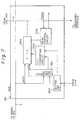
- Figure 5shows an example of the construction of the concentrator (RE) 24 shown in Fig. 4.
- the reference numerals 20 to 23are the network, the FLM, and the CATV-HE, respectively, as shown in Fig. 4, and 30 represents a concentrator (corresponding to 24 in Fig. 4).
- 31represents an optical fiber interface (represented by FINF) for handling ATM cells of usual data other than the television signals for broad casting;
- 32is an optical fiber interface (also represented by FINF) for handling the ATM cells of television signals for broad casting;
- 33is a multiplexing circuit (MUX);
- 34is an ATM switch ( ATM-SW);
- 35is a television signal cell (TV cell) inserting circuit;
- 36 and 37are subscriber circuits (SINF) provided to correspond to respective subscribers; and 38 is a call processor (CPR).
- the FINF 32In operation of the concentrator 24, when the television signals from the CATV-HE 23 are input through the FLM 21 to the FINF 32, the FINF 32 directly passes them to the TV cell inserting circuit 35 when the television signals have been made to be ATM cells. When the television signals from the FLM 21 are not made to be ATM cells, the FINF 32 makes them into ATM cells and then supplies them to the TV cell inserting circuit 35.
- ATM cells of usual data signals other than the television signalspass through the FLM 21 and FINF 31 to the multiplexing circuit (MUX) 33 ,in which a plurality of inputs (only one is shown in the figure for the sake of simplicity) are multiplexed, and then switching is effected in the ATM-SW 34.
- the output thereofis input to the demultiplexing circuit (DMX) 350 in the TV cell inserting circuit 35.
- the TV cell inserting circuit 35consists of the demultiplexing circuit (DMX) 350 and multiplexing circuits (MUX) 351 and 352 for multiplexing the ATM cells from the demultiplexing circuit 350 and the ATM cells of a channel designated from the television signals.
- DMXdemultiplexing circuit
- MUXmultiplexing circuits
- the CPR 38When the CPR 38 receives channel information of a television signal required by a subscriber through a control channel (called a D channel) that is formed between the subscriber terminal and the CPR 38 through the subscriber circuit (SINF) 36 or 37 connected to each subscriber, the CPR 38 generates an instruction, which is given to the multiplexing circuit 351 or 352 in the TV cell inserting circuit 35. Note that the CPR 38 detects the state of the transfer operations in the FINFs 31 and 32 to grasp the transfer condition of the ATM cells.
- a D channela control channel
- SIRFsubscriber circuit
- FIG. 6shows an example of the construction of the TV cell inserting circuit. Note, however, that Fig. 6 shows the construction for only the SINF 36 in the TV cell inserting circuit 35 for one subscriber.
- Fig. 6350 is a part of the demultiplexing circuit (DMX) for one subscriber.
- the demultiplexing circuit 350is represented by the same symbol 350 in Fig. 5.
- Reference numeral 351represents the multiplexing circuit (MUX) 351 in Fig. 5, and SINF 36 and CPR 38 are the same units as those shown in Fig. 5.
- a line aconducts ATM cells of usual data transferred from the ATM-SW 34 in Fig. 5.
- a line bconducts ATM cells of television signals transferred from the FINF 32.
- a line cconnects the DMX 350 and the MUX 351 to form a ring so as to conduct a tolken therethrough.
- a line dis connected to the SINF 36 that is provided to correspond to a subscriber.
- a VCI included in the header of the ATM cell and the data in a setting unit 3502, in which a VCI is allocated to the subscriberare compared by a coincidence circuit 3501.
- the coincidence circuit 3501stores the ATM cell into a memory (not shown), from which the ATM cell is output to the line d .
- the output of the ATM cell to the line dis controlled by the tolken passing through the line c that forms a loop. The control by the tolken is later described with reference to Fig. 7.
- the ATM cell of usual data other than the television signals and having a destination to the destination subscriberis separated from the other ATM cells by the demultiplexer 350 and is output therefrom.
- the coincidence circuit 3501in stead of comparing the VCIs, when a well known method is employed in which tag data corresponding to the destination is added to the ATM cell, it is also possible that tag data indicating the destination of the subscriber may be set in the setting unit 3502, and a coincidence with the tag data of the input ATM cell may be detected.
- an ATM cell of a television signalis input through the line b .
- data indicating a channelis set as a VCI when the television signal is made to be the ATM cell in the CATV-HE 23 or the FINF 32.
- VCIchannel 1
- CH2channel 2
- VCI2
- VCI2
- VCI2
- VCI2
- the CPR 38when the CPR 38 receives channel information (required channel number) of the television signal that is requested by a subscriber through the control channel (D channel), the CPR 38 sets the VCI of the channel information in a setting unit 3512 in the MUX 351. For example, when it is CH1, "1" is set.
- a coincidence circuit 3511 in the MUX 351compares the VCI in the header of the ATM cell of the television signal and the value in the setting unit 3512.
- the ATM cell of the television signalis stored in a memory (not shown) and when the MUX 351 receives the tolken through the line c , the ATM cell of the television signal is read from the memory to be output and is multiplexed with the ATM cell from the demultiplexer 350. The multiplexed ATM cells are output to the line d .
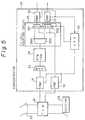
- Figure 7shows an example of the construction of the multiplexing circuit (MUX) 351 in Fig. 6.
- 3511 and 3512are the coincidence circuit and the setting circuit respectively, which are the same as those shown in Fig. 6, and 3513 is a VCI converting circuit; 3514 is a FIFO (First In First Out) register, and 3515 is a read control circuit.
- the channel number requested by a subscriber designated by the CPR 38 in Fig. 5 and the VCI data of the subscriberare set.
- a television signalabout 1.2 GHz
- the VCI in the header of the ATM cell and the channel number set in the setting unit 3512are compared in the comparing circuit 3511.
- a signal (expressed by GATE) for opening a gateis supplied to the FIFO register 3514, whereby a data signal (expressed by DATA) of the ATM cell is input to the FIFO register 3514.
- the VCI converting circuit 3513converts or rewrites the VCI representing a channel number stored in the FIFO register 3514 into the VCI data of the destination subscriber set in the setting unit 3512.
- the contents in the FIFO register 3514are read from the read control circuit 3513 in a first-in first out fashion.
- the read operationis carried out when the tolken that is circulating through the line c shown in Fig. 6 reaches the MUX 351, and the read ATM cell is output to the line d to be multiplexed with the ATM cell from the DMX 350 shown in Fig. 6.
- the multiplexed signalis supplied to the SINF (subscriber interface) 36.
- SINFsubscriber interface
- CATV television signalscan be multiplexed with ATM cells in a public network such as an ISDN or ATM network.
- a bandcan be efficiently used compared with the case when a television signal is switched in accordance with STM (synchronous transfer mode). For example, when a STM (synchronous transfer mode) is used, and if a transmission line of 150 MHz is used, the whole band of 150 MHz is used even for a 80 MHz band data. In contrast, when the 80 MHz data is made to be ATM cells, only the 80 MHz band is used. Therefore, a 70 MHz band can be saved (150MHz-80MHz) .
- STMsynchronous transfer mode
- the band in the ATM switchcan be efficiently used so that usual data communication other than the television signal obtains a margin in the frequency band. For example, if n channels of the television signals are not used in the ATM switch, about 80 MHz x n (channels) can be efficiently used.
Landscapes
- Engineering & Computer Science (AREA)
- Signal Processing (AREA)
- Multimedia (AREA)
- Computer Networks & Wireless Communication (AREA)
- Data Exchanges In Wide-Area Networks (AREA)
Description
- The present invention generally relates to atelevision signal and asynchronous transfer mode (ATM) cellswitching system for accommodating television signals sent froma cable television head end (CATV-HE) into an ATM switchingnetwork, so as to provide a subscriber with both a televisionsignal and ATM cell data other than the television signal.
- In particular, the invention relates to a system forsupplying a plurality of ATM cells corresponding to a pluralityof channels to a plurality of subscribers.
- ATM cell switching systems are describedfor example in EP-A-0 355 797 or EP-
A-0 351 818. - It has been required to switch and connect televisionsignals of a plurality of channels output from a CATV-HE to aplurality of subscribers connected to an ATM switching network,but there is no such technique in the prior art.
- An object of the present invention is to provide asystem for supplying a plurality of ATM cells corresponding toa plurality of channels to a plurality of subscribers, capableof providing an ATM cell to a subscriber connected to an ATMswitching network.
- The above object is attained by a system as set out in the claims.
- In another aspect, there is provideda television signal and ATM switching system for switchingchannels of television signals from a source and ATM cells ofdata other than said television signals from a network and forsupplying one of the channels of television signals and dataother than the said television signals to each of subscribers,comprising a television signal switching unit, operativelyconnected to the source, for switching the channels oftelevision signals to provide a plurality of televisionsignal outputs directing to the subscribers respectively, anATM switching unit for switching the ATM cells of data otherthan the television signals to provide ATM cells directedto the subscribers respectively, and a multiplexing unit, operatively connected to the output of the televisionsignal switching unit and the ATM switching unit, formultiplexing each output of the television signalswitching unit and each output of the ATM switching unitto provide a multiplexed television and data signal toone of the directed subscribers, whereby one-waycommunication of the television signals from the sourceto the subscribers and two-way communication of thedata other than the television signals between thenetwork and the subscribers are carried out.
- In the above system, the television signalswitching unit is a space-division type synchronoustransfer mode switch for switching a plurality ofchannels of the television signals in accordance withrequests from the subscribers.
- Alternatively, in the above system, the sourcehas an ATM cell generating unit for generating ATMcells of the television signals. In this case, thetelevision signal switching unit, the the ATM switchingunit, and the multiplexing unit consist of a single ATMswitch.
- According to another aspect,there is provided a television signal and anATM cell switching system in an exchange apparatus forperforming data switching of ATM cells and for supplyingone channel among television signals of a plurality ofchannels transmitted from a source to a subscriber,comprising a television signal transmitting unit fortransmitting television signals in the form of ATMcells, an ATM switching unit for switching ATM cell dataother than the television signals, a television signalcell inserting circuit, operatively connected to thetelevision signal transmitting unit and the ATMswitching unit, for receiving a plurality of channelsof television signals from the television signaltransmitting unit, and for receiving ATM cell data otherthan the television signals after being switched by the ATM switching unit. The television signal insertingcircuit comprises a demultiplexing circuit, operativelyconnected to the ATM switching unit, for demultiplexingthe output of the ATM switching unit to provide aplurality of outputs corresponding to respectivesubscribers, and a plurality of multiplexing circuits,operatively connected to the outputs of thedemultiplexing circuit respectively and connected tothe television signal transmitting unit, each formultiplexing the demultiplexed ATM cell received fromone corresponding output of the demultiplexing circuitand one channel of the ATM cells selected in accordancewith a request from the corresponding subscriber,whereby one-way communication of the television signalsfrom the source to the subscribers and two-waycommunication of data other than the television signalsbetween the network and the subscribers are carried out.
- The above system further comprises adesignated channel selecting unit, operativelyconnected to the plurality of multiplexers, forproviding a channel designating signal to each of themultiplexers in accordance with a request from thecorresponding subscriber, each of the multiplexersselecting one channel of the television signals inaccordance with the channel designating signal.
- In the above system, an ATM cell in eachchannel of the television signals is provided with aVCI area , and when one of the multiplexing circuitsdetects an ATM cell representing the television signalof the channel requested by a subscriber, themultiplexing circuit writes a VCI, indicating that thedestination of the ATM cell is the subscriber, into theVCI area.
- In the above system also, each of theplurality of multiplexing circuits in the televisionsignal inserting circuit is driven by a tolkencirculating through the plurality of multiplexing circuits to output an ATM cell to the correspondingsubscriber.
- The above object and features of the presentinvention will be more easily understood when read fromthe following description of the preferred embodimentswith reference to the drawings, wherein:
- Figure 1 is a diagram of a television signaland an ATM cell switching system according to a firstembodiment of the present invention;
- Fig. 2 is a diagram of a television signal andan ATM cell switching system according to a secondembodiment of the present invention;
- Fig. 3 is a diagram of a television signal andan ATM cell switching system according to a thirdembodiment of the present invention;
- Fig. 4 is a diagram of a network system inwhich the present invention is implemented;
- Fig. 5 is a diagram showing the constructionof a concentrator according to the third embodiment ofthe present invention;
- Fig. 6 is a diagram of a cell insertingcircuit in the concentrator shown in Fig. 5; and
- Fig. 7 is a diagram showing the constructionof the multiplexing circuit shown in Fig. 5.
- Figure 1 is a construction diagram of atelevision signal and an ATM cell switching systemaccording to a first embodiment of the presentinvention
- In Fig. 1, 60 is a cable television head end(CATV-HE) that is a source for transmitting a pluralityof channels CH0, CH1, CH2, ... of television signals,61 is a normal space-division type synchronous transfermode switch (STM-SW) for switching the televisionsignals in accordance with requests from thesubscribers to provide a plurality of television signal outputs directing to said subscribers respectively; 62is a multiplexer (MUX) for multiplexing ATM cells ofdata from a network of, for example, a public network of64 KHz, other than the television signals to outputmultiplexed ATM cells of 150 MHz, for example; 63 is anasynchronous transfer mode switch (ATM-SW) forswitching the ATM cells to output, for example, 1.2 GHzof ATM cells, 64 is a demultiplexer (DMUX) fordemultiplexing the 1.2 GHz ATM cells into ATM cells of150 MHz corresponding to respective subscribers; 65represents multiplexing circuits each for multiplexingthe television signal and the ATM cell corresponding toone subscriber; 66 represents subscriber interfacecircuits (SINF), and 67 represents network terminators(NT) each for supplying one of the channels oftelevision signals and data other than the televisionsignals to each of the subscribers.
- In the construction shown in Fig. 1, digitalsignals for usual data communication, personal computercommunication, speech sound, and so forth, are input,in the form of ATM cells, to the
multiplexer 62 and aremultiplexed, then switched and connected by the ATM-SW 63, demultiplexed by the demultiplexer to correspond torespective subscribers, and are input to themultiplexer 65. - On the other hand, cable television signals(digital signals) are output from the CATV-
HE 60 asrespective channels (CH0, CH1, ...), and are input tothe STM-SW 61. In response to requests from respectivesubscribers, the space division switch STM-SW 61performs a switching and connection by software. Thus,desired channel signals are output to the output linescorresponding to respective subscribers, and are inputto themultiplexing circuits 65 provided to correspondto therespective subscriber circuits 66. - Thus one-way communication of the televisionsignals from the source to the subscribers and two-way communication of the data other than the televisionsignals between the network and the subscribers arecarried out.
- The system shown in Fig. 1, however, has thefollowing disadvantage.
- The
respective subscriber circuits 66 areconnected through subscriber lines to thenetworkterminators 67. To eachnetwork terminator 67, aplurality of terminal adapters (not shown in Fig. 1 butare shown in Fig. 4) are connected in parallelformation. Corresponding to the terminal adapters, a TVunit, a personal computer, a data terminal, and so forthare respectively connected so that communication ispossible among a plurality of units. Note that, betweenthesubscriber circuit 66 and thenetwork terminator 67,a transmission is performed in accordance with, forexample, STS-n (Synchronous Transfer Signal Level n).When it is at level 3 (STS-3) where n = 3, atransmission is performed by 155.52 Mbps (megabits persecond). - When the STS-3 is employed, the ATM cells ateach output of the
demultiplexer 64 forms anapproximately 150 MHz band that can be divided by VCIs(Virtual Call Identifications) in the respective ATMcells. However, the television signals passed throughthe STM-SW 61 are not the ATM cells but has a broaderband than each ATM cell. When one channel of thetelevision signal is 150 MHz, and the communicationline between thesubscriber circuit 66 and a terminalof the subscriber allows only 155 MHz, the down line isoccupied by only one channel of the television signalso that communication of signals other than thetelevision signal cannot occur because the ATM cellsare temporary stored in a buffer (not shown) but thetelevision signal is a continuous signal so that it isnot buffered but selected to be output from themultiplexers 65 with a priority even while the ATM cells have to wait to pass the multiplexer. Since thetelevision signal is transmitted by one-waycommunication, the up-line becomes empty. - Even when communication from the
multiplexingcircuit 65 through thesubscriber circuit 66 to thesubscriber is made possible by, for example 600 MHz(STS-12) in stead of the above example of STS-3, and if3/4 band (450 MHz) is always reserved for the televisionsignal, then only 1/4 band (150 MHz) can be used forsignals other than the television signals. Assume thatone channel of the television signal uses 150 MHz. Then,in the above example, one subscriber always receivesthree channels of television signals simultaneously.Therefore, there is a problem in that, for communicationother than the television signal transmission, only 1/4band (150 MHz) can be used. There may be a case inwhich 150 MHz is insufficient for communication otherthan the television signal transmission. Further, inthis case, since the down direction line uses the broad3/4 band of one-way communication of the televisionsignals, the up direction line cannot use such a broadband. Therefore, there is a using rate imbalance problembetween the down line and the up line. Further, thereis bad efficiency if units for the broad band areprovided, because the units for the broad band cannotbe used in communication through the up-line. More over,the band necessary for a video image of a television isgenerally 70 to 80 MHz, and even for a HD (High Density)TV, 110 to 120 MHz so that the whole band of 150 MHzfor one channel cannot be used. - Figure 2 is a block diagram of a televisionsignal and ATM cell switching system according to asecond embodiment of the present invention, which isconsidered to remove the above disadvantage in thesystem shown in Fig. 1. In the construction in Fig. 2,68 is a concentrator (represented by RE: anabbreviation of a remote electronics) for concentrating a plurality of subscriber lines at a location far froma network such as a LAN, 680 and 681 are fiberinterfaces (FINF) for taking interfaces with the CATV-
HE 60 and a network connected through optical fibersrespectively, 682 represents multiplexing circuits, 683is an ATM-SW, 684 is a demultiplexing circuit, and theSINFs 66 are the same subscriber circuits as thoseshown in Fig. 1. - In this construction, a television signaloutput from the CATV-
HE 60 is converted by anATM cellgenerator 601 into the format of an ATM cell that isinput to theFINF 680. The signals other than thetelevision signals are input to the FINF 681. Both thetelevision signals and the usual data in the form ofATM cells are multiplexed by themultiplexing circuits 682 respectively and are switched by the ATM-SW 683.Thedemultiplexer 684 separates the ATM cells intosignals corresponding to the respective subscribers andthe separated signals are output to thesubscribercircuits 66. - Thus, one way-communication of the televisionsignal and two-way communication of data other than thetelevision signals may be possible.
- The system shown in Fig. 2, however, also hasthe following disadvantage.
- Namely, in the ATM-
SW 683, one ATM cellgenerally has only a single destination as a subscriber.Therefore, one channel of the television signal can bedelivered to only a single subscriber so that a broadcasting function, in which the signal in the samechannel is transmitted to a plurality of subscribers,cannot be realized. Even when a broad casting is madepossible in the system shown in Fig. 2 so that an ATMcell received from the CATV-HE 60 is always delivered toall subscribers, the using rate of the ATM-SW 683 isincreased so that the communication band for othercommunication (data communication, television telephone and so forth) between subscribers becomes very narrow,resulting in bad efficiency. - In more detail, in the system shown in Fig. 2,when an ATM cell provided with a VCI for each channelof the respective television channel is sent, theconcentrator RE cannot perform a broad casting function,because in the exchanging operation, one cell istransferred to only a single target location(destination). If an exchange operation is made so thata broad casting cell is delivered to all subscribers,there is a problem in that memories provided at therespective cross points of the ATM-SW are always used,for example, n × 80 MHz (n is the number of the broadcasting channels) so that the band to be used for otherpurposes (data communication, television telephone,personal computer communication and so forth) becomesnarrow.
- Since the television signal requires anextremely broad transmission band, efficient exchangeand connection cannot be performed by the system shownin Fig. 1 or Fig. 2. Therefore, an improvement thereofhas been desired.
- Fig. 3 is a diagram of a television signal andATM cell switching system according to a thirdembodiment of the present invention.
- In Fig. 3, 1 is a cell inserting unit forinserting a television signal cell of a designatedchannel into data signal cells output from an ATMswitch other than the television signals; 10 is ademultiplexing circuit; 11 represents multiplexingcircuits provided to correspond to respectivesubscribers; 2 is a designated channel selecting unit; 3is the ATM switch ( ATM-SW), and 4 is a televisionsignal transmitting unit for transmitting multichanneltelevision signals that are made to be ATM cells by an
ATM cell generator 41. - As can be seen from Fig. 3, in the third embodiment of the present invention, the televisionsignals that are made to be the ATM cells by the
ATMcell generator 41 are inserted, without passing throughtheATM switch 3, in a portion of a subscriber interface. - In an operation of the system shown in Fig. 3,ATM cells of data signals other than the televisionsignals are output from the
ATM switch 3 and are inputto thecell inserting unit 1. In each ATM cell, as iswell known, a VPI (Virtual Path Identification number)and a VCI (Virtual Channel Identification number) areincluded in the header, i.e., the heading five octets ofthe ATM cell. The VCI indicates a particular subscriberas a destination of the ATM cell. Thedemultiplexingcircuit 10 separates the ATM cells to be directed todestination subscribers in accordance with the VCIs.The separated ATM cells are input to themultiplexers 11corresponding to the respective subscribers. Note that,in Fig. 3, for the sake of simplicity, only twomultiplexers 11 are shown, however, the number ofmultiplexers is the same as the number of subscribers. - On the other hand, from the television signaltransmitting unit 4, multi-channel television signalsare output as multiplexed ATM cells and are input tothe
respective multiplexing circuits 11 in thecellinserting unit 1. The ATM cells from thedemultiplexingcircuit 10 and one channel of the television signalsselected from the multi-channel television signalsoutput from the television signal transmitting unit 4are selected and are multiplexed to be transmitted tothe subscriber sides. - The channel to be selected from the multi-channeltelevision signals is designated by thedesignated
channel selecting unit 2. When thedesignatedchannel selecting unit 2 receives, through aD channel that is used in an integrated servicesdigital network (ISDN) as a channel for passing controlsignals between a subscriber and the switch, the number of the channel that is desired by a subscriber, theunit 2 outputs an instruction to select the said channel toone or more of the multiplexingcircuits 11. - In response to the instruction, each of themultiplexing
circuits 11 detects the ATM cell of thetelevision signal of the requested channel among thetelevision signals of a plurality of channels, convertsthe destination (VCI) in the cell into a VCI of thesubscriber connected to themultiplexing circuit 11,and transmits the cell to the subscriber side. - Thus, the respective subscribers can receive,from the multiplexing
circuits 11, ATM cells of datasignals other than the television signals and ATM cellsof the television signal of the requesting channel. - Figure 4 is a system construction diagram of anetwork in which the present invention is implemented;Fig. 5 is a diagram of the construction of anembodiment of a concentrator; Fig. 6 is a diagram ofthe construction of a cell inserting unit; and Fig. 7 isa diagram of the construction of a multiplexing circuit.
- In Fig. 4, 20 is a network, such as a localarea network (LAN), formed to be a loop by an opticalcable for television broad casting (for one-waycommunication in the down side) and two optical cablesfor various data other than the television signals (fortwo-way communication); 21 represents optical fiber loopmultiplexers (represented by FLM) for connectingvarious units to the
network 20; 22 is a control office(CO); 23 is a CATV-HE for television broad castingcontrolled by thecontrol office 22; 24 representsconcentrators (represented by RE) for concentratingplural subscriber lines and for performing switching andconnection; 25 represents network terminators (NT) ofthe respective subscriber lines, 26 represent terminaladapters (represented by TA) for taking interfacesbetween a plurality of terminals to be connected to therespective subscriber lines and the NTs. - With respect to usual data signals betweenplural subscribers other than the television signals,paths are set from a
concentrator 24 through aFLM 21,thenetwork 20, anotherFLM 21, aconcentrator 24, anetwork termination (NT) 25, and terminal adapters (TA)26, to various terminals (personal computers, facsimilemachines, telephone sets, etc., which are not shown inthe figure), so that communication by using ATM cellsis performed therebetween. - The television signals of plural channels fromthe CATV-
HE 23 for television broad casting are made tobe ATM cells in the CATV-HE 23 or are made to be ATMcells at some stage along the way (for example, at theRE 24). Then, the ATM cells are transmitted through anoptical cable for the television signals in the network(NW) 20 to FLMs 21 to which theconcentrators 24 areconnected. In theFLMs 21, the ATM cells are branchedand are input to the concentrators (RE) 24 from whichthe ATM cells reach the network terminators (NT) 25corresponding to the respective subscribers. From thenetwork terminators (NT) 25, the ATM cells are suppliedto one of the TV terminals (not shown) in therespective terminal adapters (TA) 26 for thesubscribers. - Figure 5 shows an example of the constructionof the concentrator (RE) 24 shown in Fig. 4.
- In Fig. 5, the
reference numerals 20 to 23 arethe network, the FLM, and the CATV-HE, respectively, asshown in Fig. 4, and 30 represents a concentrator(corresponding to 24 in Fig. 4). In theconcentrator - In operation of the
concentrator 24, when thetelevision signals from the CATV-HE 23 are inputthrough theFLM 21 to theFINF 32, theFINF 32 directlypasses them to the TVcell inserting circuit 35 when thetelevision signals have been made to be ATM cells. Whenthe television signals from theFLM 21 are not made tobe ATM cells, theFINF 32 makes them into ATM cells andthen supplies them to the TVcell inserting circuit 35. - ATM cells of usual data signals other than thetelevision signals pass through the
FLM 21 andFINF 31to the multiplexing circuit (MUX) 33 ,in which aplurality of inputs (only one is shown in the figure forthe sake of simplicity) are multiplexed, and thenswitching is effected in the ATM-SW 34. The outputthereof is input to the demultiplexing circuit (DMX) 350in the TVcell inserting circuit 35. - The TV
cell inserting circuit 35 consists ofthe demultiplexing circuit (DMX) 350 and multiplexingcircuits (MUX) 351 and 352 for multiplexing the ATMcells from thedemultiplexing circuit 350 and the ATMcells of a channel designated from the televisionsignals. - When the
CPR 38 receives channel information ofa television signal required by a subscriber through acontrol channel (called a D channel) that is formedbetween the subscriber terminal and theCPR 38 throughthe subscriber circuit (SINF) 36 or 37 connected toeach subscriber, theCPR 38 generates an instruction,which is given to themultiplexing circuit cell inserting circuit 35. Note that theCPR 38 detects the state of the transfer operations in theFINFs - Figure 6 shows an example of the construction of the TV cell inserting circuit. Note, however, thatFig. 6 shows the construction for only the
SINF 36 inthe TVcell inserting circuit 35 for one subscriber. - In Fig. 6, 350 is a part of the demultiplexingcircuit (DMX) for one subscriber. The
demultiplexingcircuit 350 is represented by thesame symbol 350 inFig. 5.Reference numeral 351 represents themultiplexing circuit (MUX) 351 in Fig. 5, andSINF 36andCPR 38 are the same units as those shown in Fig. 5.A linea conducts ATM cells of usual data transferredfrom the ATM-SW 34 in Fig. 5. A lineb conducts ATMcells of television signals transferred from theFINF 32. A linec connects theDMX 350 and theMUX 351 toform a ring so as to conduct a tolken therethrough. Anda lined is connected to theSINF 36 that is providedto correspond to a subscriber. - In operation of the device shown in Fig. 6,when an ATM cell of usual data from the linea is inputto the
DMX 350, a VCI included in the header of the ATMcell and the data in asetting unit 3502, in which aVCI is allocated to the subscriber, are compared by acoincidence circuit 3501. When they coincide, thecoincidence circuit 3501 stores the ATM cell into amemory (not shown), from which the ATM cell is output tothe lined. The output of the ATM cell to the line dis controlled by the tolken passing through the linecthat forms a loop. The control by the tolken is laterdescribed with reference to Fig. 7. Thus, the ATM cellof usual data other than the television signals andhaving a destination to the destination subscriber isseparated from the other ATM cells by thedemultiplexer 350 and is output therefrom. - Note that, in the
coincidence circuit 3501, instead of comparing the VCIs, when a well known method isemployed in which tag data corresponding to thedestination is added to the ATM cell, it is alsopossible that tag data indicating the destination of the subscriber may be set in thesetting unit 3502, and acoincidence with the tag data of the input ATM cell maybe detected. - To the
multiplexing circuit 351, an ATM cell ofa television signal is input through the lineb. In theheader of the ATM cell of the television signal, dataindicating a channel is set as a VCI when thetelevision signal is made to be the ATM cell in theCATV-HE 23 or theFINF 32. For example, CH1 (channel 1)is expressed by VCI = 1, CH2 is expressed by VCI = 2, ..., and CHn is expressed by VCI = n. - On the other hand, as described with referenceto Fig. 5, when the
CPR 38 receives channel information(required channel number) of the television signal thatis requested by a subscriber through the controlchannel (D channel), theCPR 38 sets the VCI of thechannel information in asetting unit 3512 in theMUX 351. For example, when it is CH1, "1" is set. Acoincidence circuit 3511 in theMUX 351 compares the VCIin the header of the ATM cell of the television signaland the value in thesetting unit 3512. When theycoincide, the ATM cell of the television signal isstored in a memory (not shown) and when theMUX 351receives the tolken through the linec, the ATM cellof the television signal is read from the memory to beoutput and is multiplexed with the ATM cell from thedemultiplexer 350. The multiplexed ATM cells are outputto the lined. - Figure 7 shows an example of the constructionof the multiplexing circuit (MUX) 351 in Fig. 6.
- In Fig. 7, 3511 and 3512 are the coincidencecircuit and the setting circuit respectively, which arethe same as those shown in Fig. 6, and 3513 is a VCIconverting circuit; 3514 is a FIFO (First In First Out)register, and 3515 is a read control circuit.
- In an operation of the circuit shown in Fig. 7,in the
setting unit 3512, the channel number requested by a subscriber designated by theCPR 38 in Fig. 5 andthe VCI data of the subscriber (VCI allocated forcommunication with the destination subscriber) are set.When a television signal (about 1.2 GHz) is inputthrough the lineb to theMUX 351, the VCI in theheader of the ATM cell and the channel number set inthesetting unit 3512 are compared in the comparingcircuit 3511. When they coincide, a signal (expressed byGATE) for opening a gate is supplied to theFIFOregister 3514, whereby a data signal (expressed by DATA)of the ATM cell is input to theFIFO register 3514. - Also, by the coincidence output from the
coincidence circuit 3511, theVCI converting circuit 3513 is driven. TheVCI converting circuit 3513converts or rewrites the VCI representing a channelnumber stored in theFIFO register 3514 into the VCIdata of the destination subscriber set in thesettingunit 3512. - The contents in the
FIFO register 3514 are readfrom theread control circuit 3513 in a first-in firstout fashion. The read operation is carried out when thetolken that is circulating through the linec shown inFig. 6 reaches theMUX 351, and the read ATM cell isoutput to the lined to be multiplexed with the ATM cellfrom theDMX 350 shown in Fig. 6. The multiplexedsignal is supplied to the SINF (subscriber interface)36. Although the detailed construction of the DMX 350(Fig. 6) is not shown, similar to Fig. 7, an ATM cellof usual data other than the television signal istemporarily stored in a FIFO, and when the tolkenreaches theDMX 350, the ATM cell is read out to thelined. - From the foregoing description, it will beapparent that, according to the present invention, CATVtelevision signals can be multiplexed with ATM cells ina public network such as an ISDN or ATM network. Further,a band can be efficiently used compared with the case when a television signal is switched in accordance withSTM (synchronous transfer mode). For example, when a STM(synchronous transfer mode) is used, and if atransmission line of 150 MHz is used, the whole band of150 MHz is used even for a 80 MHz band data. Incontrast, when the 80 MHz data is made to be ATM cells,only the 80 MHz band is used. Therefore, a 70 MHz bandcan be saved (150MHz-80MHz) .
- Also, by inserting the television signalwithout passing through an ATM switch and before thesubscriber circuit (SINF), the band in the ATM switchcan be efficiently used so that usual datacommunication other than the television signal obtains amargin in the frequency band. For example, if nchannels of the television signals are not used in theATM switch, about 80 MHz x n (channels) can beefficiently used.
Claims (6)
- A system for supplying a plurality of ATM cells eachconveying information corresponding to one of aplurality of broadcast channels to a plurality ofsubscribers, comprising:a detection means (3511, 3512) for detecting an ATM cellconveying information corresponding to one of theplurality of broadcast channels which one of theplurality of subscribers requests to receive; andan output means (3513, 3514, 3515) for outputting saidATM cell detected by the detection means, to said one ofthe plurality of subscriber requesting the ATM cell;each of said plurality of ATM cells contains broadcastchannel information indicating the broadcast channel ofthe information conveyed by said each ATM cell, and saiddetection means detects the ATM cell requested by thesubscriber, based on the broadcast channel information.
- A system according to claim 1, wherein each of saidplurality of ATM cells contains a VCI area, and saidbroadcast chanel information is contained in the VCIarea, and said output means contains a means (3513) forrewriting the VCI area of said ATM cell detected by thedetection means with destination information directed tothe subscriber requesting the ATM cell.
- A system according to claim 1, further comprisingcontrol means (38) for providing a requested broadcastchannel designating signal to the detection means inaccordance with a request from the correspondingsubscriber.
- A system according to one or more of claims 1 and 2,further comprising
a demultiplexing circuit (10) for receiving other ATMcells having VCI areas each containing destinationinformation directed to one of the plurality ofsubscribers, and outputting said other ATM cells tocorresponding ones of the plurality of subscribers,based on the destination information. - A system as claimed in claim 3, wherein the outputs fromthe output means and the demultiplexing circuit arecontrolled by using a token being provided for eachsubscriber and circulating between said output means andsaid demultiplexing circuit.
- A system according to one or more of claims 1 to 5,wherein said broadcast channel information indicates atelevision channel.
Applications Claiming Priority (4)
| Application Number | Priority Date | Filing Date | Title |
|---|---|---|---|
| JP108059/91 | 1991-05-14 | ||
| JP10805991AJP2938611B2 (en) | 1991-05-14 | 1991-05-14 | TV signal exchange system |
| JP10805991 | 1991-05-14 | ||
| EP19920108080EP0513763B1 (en) | 1991-05-14 | 1992-05-13 | Television signal and ATM cell switching system |
Related Parent Applications (2)
| Application Number | Title | Priority Date | Filing Date |
|---|---|---|---|
| EP92108080.0Division | 1992-05-13 | ||
| EP19920108080DivisionEP0513763B1 (en) | 1991-05-14 | 1992-05-13 | Television signal and ATM cell switching system |
Publications (3)
| Publication Number | Publication Date |
|---|---|
| EP0715470A2 EP0715470A2 (en) | 1996-06-05 |
| EP0715470A3 EP0715470A3 (en) | 1996-08-14 |
| EP0715470B1true EP0715470B1 (en) | 2000-07-19 |
Family
ID=14474867
Family Applications (2)
| Application Number | Title | Priority Date | Filing Date |
|---|---|---|---|
| EP19960101410Expired - LifetimeEP0715470B1 (en) | 1991-05-14 | 1992-05-13 | System for supplying a plurality of ATM cells |
| EP19920108080Expired - LifetimeEP0513763B1 (en) | 1991-05-14 | 1992-05-13 | Television signal and ATM cell switching system |
Family Applications After (1)
| Application Number | Title | Priority Date | Filing Date |
|---|---|---|---|
| EP19920108080Expired - LifetimeEP0513763B1 (en) | 1991-05-14 | 1992-05-13 | Television signal and ATM cell switching system |
Country Status (5)
| Country | Link |
|---|---|
| US (1) | US5513180A (en) |
| EP (2) | EP0715470B1 (en) |
| JP (1) | JP2938611B2 (en) |
| CA (1) | CA2068387C (en) |
| DE (2) | DE69213317T2 (en) |
Families Citing this family (101)
| Publication number | Priority date | Publication date | Assignee | Title |
|---|---|---|---|---|
| EP0580011A3 (en)* | 1992-07-23 | 1994-09-14 | Siemens Ag | Method for the transmission of digital video and audio signals and suitable receiving apparatus |
| US7269841B1 (en) | 1992-12-09 | 2007-09-11 | Sedna Patent Services, Llc | Digital cable headend for cable television delivery system |
| US8073695B1 (en) | 1992-12-09 | 2011-12-06 | Adrea, LLC | Electronic book with voice emulation features |
| US5659350A (en) | 1992-12-09 | 1997-08-19 | Discovery Communications, Inc. | Operations center for a television program packaging and delivery system |
| NZ259147A (en) | 1992-12-09 | 1997-05-26 | Discovery Communicat Inc | Network controller for cable television |
| US5600364A (en) | 1992-12-09 | 1997-02-04 | Discovery Communications, Inc. | Network controller for cable television delivery systems |
| US7509270B1 (en) | 1992-12-09 | 2009-03-24 | Discovery Communications, Inc. | Electronic Book having electronic commerce features |
| US7073187B1 (en) | 1992-12-09 | 2006-07-04 | Sedna Patent Services, Llc | Menu-driven television program access system and method |
| US5600573A (en) | 1992-12-09 | 1997-02-04 | Discovery Communications, Inc. | Operations center with video storage for a television program packaging and delivery system |
| US7849393B1 (en) | 1992-12-09 | 2010-12-07 | Discovery Communications, Inc. | Electronic book connection to world watch live |
| US9286294B2 (en) | 1992-12-09 | 2016-03-15 | Comcast Ip Holdings I, Llc | Video and digital multimedia aggregator content suggestion engine |
| US7168084B1 (en) | 1992-12-09 | 2007-01-23 | Sedna Patent Services, Llc | Method and apparatus for targeting virtual objects |
| US7401286B1 (en) | 1993-12-02 | 2008-07-15 | Discovery Communications, Inc. | Electronic book electronic links |
| US7835989B1 (en) | 1992-12-09 | 2010-11-16 | Discovery Communications, Inc. | Electronic book alternative delivery systems |
| US7336788B1 (en) | 1992-12-09 | 2008-02-26 | Discovery Communicatoins Inc. | Electronic book secure communication with home subsystem |
| US5425027A (en)* | 1993-01-04 | 1995-06-13 | Com21, Inc. | Wide area fiber and TV cable fast packet cell network |
| US5539449A (en)* | 1993-05-03 | 1996-07-23 | At&T Corp. | Integrated television services system |
| CA2165424A1 (en)* | 1993-06-16 | 1994-12-22 | Paul Baran | Multiple protocol personal communications network system |
| US7861166B1 (en) | 1993-12-02 | 2010-12-28 | Discovery Patent Holding, Llc | Resizing document pages to fit available hardware screens |
| US8095949B1 (en) | 1993-12-02 | 2012-01-10 | Adrea, LLC | Electronic book with restricted access features |
| US9053640B1 (en) | 1993-12-02 | 2015-06-09 | Adrea, LLC | Interactive electronic book |
| US7865567B1 (en) | 1993-12-02 | 2011-01-04 | Discovery Patent Holdings, Llc | Virtual on-demand electronic book |
| EP0803156B1 (en) | 1994-05-05 | 2004-12-01 | Sprint Communications Company, L.P. | Method, system and apparatus for telecommunications control |
| US5991301A (en)* | 1994-05-05 | 1999-11-23 | Sprint Communications Co. L.P. | Broadband telecommunications system |
| US6633561B2 (en) | 1994-05-05 | 2003-10-14 | Sprint Communications Company, L.P. | Method, system and apparatus for telecommunications control |
| US6631133B1 (en) | 1994-05-05 | 2003-10-07 | Sprint Communications Company L.P. | Broadband telecommunications system |
| US6031840A (en)* | 1995-12-07 | 2000-02-29 | Sprint Communications Co. L.P. | Telecommunications system |
| US6430195B1 (en)* | 1994-05-05 | 2002-08-06 | Sprint Communications Company L.P. | Broadband telecommunications system interface |
| US5920562A (en) | 1996-11-22 | 1999-07-06 | Sprint Communications Co. L.P. | Systems and methods for providing enhanced services for telecommunication call |
| US6181703B1 (en) | 1995-09-08 | 2001-01-30 | Sprint Communications Company L. P. | System for managing telecommunications |
| DE4425197C2 (en)* | 1994-07-16 | 1998-07-09 | Deutsche Telekom Ag | Method for return channel transmission in broadband distribution networks |
| US5757798A (en)* | 1994-07-21 | 1998-05-26 | Hitachi, Ltd. | Image information distribution system |
| CN1122087A (en)* | 1994-07-21 | 1996-05-08 | 株式会社日立制作所 | Image Information Distribution System |
| EP0701384B1 (en)* | 1994-09-09 | 2003-01-02 | Alcatel | System, subscriber equipment, central and method for video on demand |
| CA2199815C (en)* | 1994-09-12 | 2001-07-24 | Catherine W. Jelinek | Cable television apparatus employing two-way communication |
| DE4433898C2 (en)* | 1994-09-22 | 1997-08-14 | Siemens Ag | Broadband information system for interactive services |
| CA2143977C (en)* | 1995-01-31 | 1997-03-18 | Mark Krebs | Video mail delivery system |
| EP0735766B1 (en)* | 1995-03-31 | 2002-07-03 | Sony Service Centre (Europe) N.V. | A video service system with VCR function |
| EP0735763B1 (en) | 1995-03-31 | 2000-07-05 | Sony Europa B.V. | A system for information on demand |
| JP3231575B2 (en)* | 1995-04-18 | 2001-11-26 | 三菱電機株式会社 | Wireless data transmission equipment |
| US6209132B1 (en) | 1995-06-15 | 2001-03-27 | Intel Corporation | Host apparatus for simulating two way connectivity for one way data streams |
| US6072521A (en)* | 1995-06-15 | 2000-06-06 | Intel Corporation | Hand held apparatus for simulating two way connectivity for one way data streams |
| US6064420A (en)* | 1995-06-15 | 2000-05-16 | Intel Corporation | Simulating two way connectivity for one way data streams for multiple parties |
| US5818441A (en)* | 1995-06-15 | 1998-10-06 | Intel Corporation | System and method for simulating two-way connectivity for one way data streams |
| US5826166A (en)* | 1995-07-06 | 1998-10-20 | Bell Atlantic Network Services, Inc. | Digital entertainment terminal providing dynamic execution in video dial tone networks |
| US5996019A (en) | 1995-07-19 | 1999-11-30 | Fujitsu Network Communications, Inc. | Network link access scheduling using a plurality of prioritized lists containing queue identifiers |
| AU717210B2 (en)* | 1995-09-07 | 2000-03-23 | Nec Australia Pty Ltd | A distribution system |
| WO1997009827A1 (en)* | 1995-09-07 | 1997-03-13 | Nec Australia Pty. Ltd. | A distribution system |
| WO1997010656A1 (en) | 1995-09-14 | 1997-03-20 | Fujitsu Network Communications, Inc. | Transmitter controlled flow control for buffer allocation in wide area atm networks |
| US6687244B1 (en) | 1995-11-22 | 2004-02-03 | Sprint Communications Company, L.P. | ATM transport system |
| US7003796B1 (en)* | 1995-11-22 | 2006-02-21 | Samsung Information Systems America | Method and apparatus for recovering data stream clock |
| AU1697697A (en) | 1996-01-16 | 1997-08-11 | Fujitsu Limited | A reliable and flexible multicast mechanism for atm networks |
| WO1997028622A1 (en)* | 1996-02-02 | 1997-08-07 | Sprint Communications Company, L.P. | Atm gateway system |
| AU6350196A (en)* | 1996-07-08 | 1998-02-02 | Mark Sinclair Krebs | Video mail delivery system |
| JPH1065670A (en)* | 1996-08-13 | 1998-03-06 | Nec Corp | Atm concentrator |
| US5748905A (en) | 1996-08-30 | 1998-05-05 | Fujitsu Network Communications, Inc. | Frame classification using classification keys |
| US6028860A (en)* | 1996-10-23 | 2000-02-22 | Com21, Inc. | Prioritized virtual connection transmissions in a packet to ATM cell cable network |
| WO1998020638A1 (en)* | 1996-11-08 | 1998-05-14 | 3Com | Mechanism to support a utopia interface over a backplane |
| US6014378A (en) | 1996-11-22 | 2000-01-11 | Sprint Communications Company, L.P. | Telecommunications tandem system for circuit-based traffic |
| US6002689A (en) | 1996-11-22 | 1999-12-14 | Sprint Communications Co. L.P. | System and method for interfacing a local communication device |
| US5905942A (en)* | 1997-02-18 | 1999-05-18 | Lodgenet Entertainment Corporation | Multiple dwelling unit interactive audio/video distribution system |
| US5946048A (en)* | 1997-03-12 | 1999-08-31 | Hybrid Networks, Inc. | Network device for handling digital data over a TV channel |
| US5946047A (en)* | 1997-03-12 | 1999-08-31 | Hybrid Networks, Inc. | Network system for handling digital data over a TV channel |
| US6067299A (en) | 1997-04-16 | 2000-05-23 | Sprint Communications Company, L.P. | Communications system for providing ATM connections and echo cancellation |
| US6137800A (en) | 1997-05-09 | 2000-10-24 | Sprint Communications Company, L. P. | System and method for connecting a call |
| US6704327B1 (en) | 1997-05-09 | 2004-03-09 | Sprint Communications Company, L.P. | System and method for connecting a call |
| US6178170B1 (en) | 1997-05-13 | 2001-01-23 | Sprint Communications Company, L. P. | System and method for transporting a call |
| AUPO894297A0 (en)* | 1997-09-02 | 1997-09-25 | Nec Australia Pty Ltd | A distribution system |
| US6031576A (en)* | 1997-09-08 | 2000-02-29 | Kuykendall, Jr.; Jacob L. | Method and system for over-the-air broadcast of HDTV and the like with efficient spectrum allocation and broadcast area signal distribution |
| JP3831092B2 (en)* | 1997-09-19 | 2006-10-11 | 富士通株式会社 | server |
| US6470019B1 (en) | 1998-02-20 | 2002-10-22 | Sprint Communications Company L.P. | System and method for treating a call for call processing |
| US6546022B1 (en)* | 1998-04-03 | 2003-04-08 | Sprint Communications Company, L.P. | Method, system and apparatus for processing information in a telecommunications system |
| US9009773B1 (en) | 1998-06-30 | 2015-04-14 | Cox Communications, Inc. | Method and apparatus for providing broadcast data services |
| US6597701B1 (en) | 1998-12-22 | 2003-07-22 | Sprint Communications Company L.P. | System and method for configuring a local service control point with a call processor in an architecture |
| US6724765B1 (en) | 1998-12-22 | 2004-04-20 | Sprint Communications Company, L.P. | Telecommunication call processing and connection system architecture |
| US6785282B1 (en) | 1998-12-22 | 2004-08-31 | Sprint Communications Company L.P. | System and method for connecting a call with a gateway system |
| US6888833B1 (en) | 1998-12-22 | 2005-05-03 | Sprint Communications Company L.P. | System and method for processing call signaling |
| US6982950B1 (en) | 1998-12-22 | 2006-01-03 | Sprint Communications Company L.P. | System and method for connecting a call in a tandem architecture |
| US7079530B1 (en) | 1999-02-25 | 2006-07-18 | Sprint Communications Company L.P. | System and method for caching toll free number information |
| US6560226B1 (en) | 1999-02-25 | 2003-05-06 | Sprint Communications Company, L.P. | System and method for caching ported number information |
| EP1041825A1 (en)* | 1999-03-31 | 2000-10-04 | Alcatel | Broadcasting unit to broadcast distributive interactive services in an access network |
| FR2794591B1 (en)* | 1999-06-03 | 2001-06-29 | France Telecom | INTERNAL INSTALLATION OF ATM-BASED MULTI-TERMINAL CLIENT |
| US6816497B1 (en) | 1999-11-05 | 2004-11-09 | Sprint Communications Company, L.P. | System and method for processing a call |
| US6785377B1 (en) | 2000-01-19 | 2004-08-31 | Sprint Communications Company L.P. | Data calls using both constant bit rate and variable bit rate connections |
| US7263712B2 (en)* | 2001-05-29 | 2007-08-28 | Intel Corporation | Enabling a PC-DTV receiver to share the resource cache with multiple clients |
| US7793326B2 (en) | 2001-08-03 | 2010-09-07 | Comcast Ip Holdings I, Llc | Video and digital multimedia aggregator |
| US7908628B2 (en) | 2001-08-03 | 2011-03-15 | Comcast Ip Holdings I, Llc | Video and digital multimedia aggregator content coding and formatting |
| US8630306B2 (en)* | 2006-01-09 | 2014-01-14 | At&T Intellectual Property I, L.P. | Fast channel change apparatus and method for IPTV |
| US20090070829A1 (en)* | 2007-09-11 | 2009-03-12 | The Directv Group, Inc. | Receiving circuit module for receiving and encoding channel signals and method for operating the same |
| US9756290B2 (en)* | 2007-09-11 | 2017-09-05 | The Directv Group, Inc. | Method and system for communicating between a local collection facility and a remote facility |
| US8973058B2 (en)* | 2007-09-11 | 2015-03-03 | The Directv Group, Inc. | Method and system for monitoring and simultaneously displaying a plurality of signal channels in a communication system |
| US9300412B2 (en)* | 2007-09-11 | 2016-03-29 | The Directv Group, Inc. | Method and system for operating a receiving circuit for multiple types of input channel signals |
| US9313457B2 (en) | 2007-09-11 | 2016-04-12 | The Directv Group, Inc. | Method and system for monitoring a receiving circuit module and controlling switching to a back-up receiving circuit module at a local collection facility from a remote facility |
| US8988986B2 (en) | 2007-09-12 | 2015-03-24 | The Directv Group, Inc. | Method and system for controlling a back-up multiplexer in a local collection facility from a remote facility |
| US8724635B2 (en)* | 2007-09-12 | 2014-05-13 | The Directv Group, Inc. | Method and system for controlling a back-up network adapter in a local collection facility from a remote facility |
| US9037074B2 (en)* | 2007-10-30 | 2015-05-19 | The Directv Group, Inc. | Method and system for monitoring and controlling a local collection facility from a remote facility through an IP network |
| US9049354B2 (en)* | 2007-10-30 | 2015-06-02 | The Directv Group, Inc. | Method and system for monitoring and controlling a back-up receiver in local collection facility from a remote facility using an IP network |
| US9049037B2 (en)* | 2007-10-31 | 2015-06-02 | The Directv Group, Inc. | Method and system for monitoring and encoding signals in a local facility and communicating the signals between a local collection facility and a remote facility using an IP network |
| US9762973B2 (en)* | 2008-11-04 | 2017-09-12 | The Directv Group, Inc. | Method and system for operating a receiving circuit module to encode a channel signal into multiple encoding formats |
| US8451921B2 (en)* | 2009-10-28 | 2013-05-28 | Qualcomm Incorporated | Method and an apparatus for adaptively learning a sparse impulse response of a continuous channel |
| US9831971B1 (en) | 2011-04-05 | 2017-11-28 | The Directv Group, Inc. | Method and system for operating a communication system encoded into multiple independently communicated encoding formats |
Family Cites Families (8)
| Publication number | Priority date | Publication date | Assignee | Title |
|---|---|---|---|---|
| CA1142244A (en)* | 1979-08-22 | 1983-03-01 | Eric J. Gargini | Wired broadcasting system with subscriber controlled switched programme selection |
| US4509073A (en)* | 1982-04-29 | 1985-04-02 | Packet Technologies, Inc. | Two-way cable-television system |
| US4831616A (en)* | 1987-03-31 | 1989-05-16 | Huber David R | Multiplexed fiber optics wideband data distribution system |
| EP0809381B1 (en)* | 1988-07-22 | 2004-11-24 | Hitachi, Ltd. | ATM switching system |
| JP3132564B2 (en)* | 1988-08-26 | 2001-02-05 | 株式会社日立製作所 | ATM switch |
| US4901367A (en)* | 1988-11-30 | 1990-02-13 | Victor Nicholson | Cable communications system with remote switching and processing converters |
| US4947244A (en)* | 1989-05-03 | 1990-08-07 | On Command Video Corporation | Video selection and distribution system |
| US5115426A (en)* | 1990-03-30 | 1992-05-19 | At&T Bell Laboratories | Broadband isdn packet switching arrangements |
- 1991
- 1991-05-14JPJP10805991Apatent/JP2938611B2/ennot_activeExpired - Fee Related
- 1992
- 1992-05-11CACA 2068387patent/CA2068387C/ennot_activeExpired - Fee Related
- 1992-05-13DEDE69213317Tpatent/DE69213317T2/ennot_activeExpired - Fee Related
- 1992-05-13EPEP19960101410patent/EP0715470B1/ennot_activeExpired - Lifetime
- 1992-05-13DEDE69231285Tpatent/DE69231285T2/ennot_activeExpired - Fee Related
- 1992-05-13EPEP19920108080patent/EP0513763B1/ennot_activeExpired - Lifetime
- 1994
- 1994-03-15USUS08/213,997patent/US5513180A/ennot_activeExpired - Fee Related
Also Published As
| Publication number | Publication date |
|---|---|
| EP0715470A3 (en) | 1996-08-14 |
| DE69213317D1 (en) | 1996-10-10 |
| DE69231285D1 (en) | 2000-08-24 |
| EP0715470A2 (en) | 1996-06-05 |
| JPH04336830A (en) | 1992-11-25 |
| CA2068387A1 (en) | 1992-11-15 |
| CA2068387C (en) | 1998-09-15 |
| US5513180A (en) | 1996-04-30 |
| EP0513763A2 (en) | 1992-11-19 |
| EP0513763B1 (en) | 1996-09-04 |
| JP2938611B2 (en) | 1999-08-23 |
| DE69213317T2 (en) | 1997-02-20 |
| DE69231285T2 (en) | 2000-12-28 |
| EP0513763A3 (en) | 1993-03-03 |
Similar Documents
| Publication | Publication Date | Title |
|---|---|---|
| EP0715470B1 (en) | System for supplying a plurality of ATM cells | |
| JP2889013B2 (en) | Packet switching system | |
| US6002692A (en) | Line interface unit for adapting broad bandwidth network to lower bandwidth network fabric | |
| US5623493A (en) | Multiplexer demultiplexer switching device and network adapter | |
| US5812550A (en) | Asynchronous transfer mode (ATM) layer function processing apparatus with an enlarged structure | |
| EP0332197B1 (en) | A ring transmission system | |
| US20020097745A1 (en) | Service unit for a hub having multiple star interconnect configurations | |
| RU2209523C2 (en) | Adaptive level 2a (al2a) processing device and method for asynchronous transmission mode network | |
| JP3073248B2 (en) | Point-to-multipoint connection method | |
| JPH1065670A (en) | Atm concentrator | |
| EP0498407B1 (en) | Congestion relieving system in a communication system | |
| GB2285366A (en) | Asynchronous data transfer | |
| JPH09284344A (en) | ATM / STM mixed network system | |
| EP0942617B1 (en) | Short cell multiplexing apparatus and method | |
| JPH02140037A (en) | ATM switch | |
| JPH10233745A (en) | Multiplex transmission method and system | |
| RU2134024C1 (en) | Device and method of processing of elements of data on mode of asynchronous transmission in system of commutation of mode of asynchronous transmission | |
| KR100419110B1 (en) | Telecommunication network elements, synchronous and asynchronous transfer mode payload delivery method, and asynchronous transfer mode cell generation device | |
| JP2002077210A (en) | Pon transmission system, atm-pon transmission system, optical network equipment, and optical circuit terminating device | |
| KR100237883B1 (en) | Efficient method for cell routing in atm vp cross connector using the method | |
| KR100372876B1 (en) | Apparatus And Method For Subscriber Interface Of STM-4C Grade | |
| KR970002713B1 (en) | Atm cell add/drop multiplexer in the ring structure for real-time communication | |
| JP2777907B2 (en) | Control channel multiplexing transmission system | |
| JPH0310543A (en) | Subscriber system constitution system for broad band isdn | |
| US7120506B1 (en) | Method, system, converter and switch for asynchronous transmission-mode (ATM) communication |
Legal Events
| Date | Code | Title | Description |
|---|---|---|---|
| PUAI | Public reference made under article 153(3) epc to a published international application that has entered the european phase | Free format text:ORIGINAL CODE: 0009012 | |
| AC | Divisional application: reference to earlier application | Ref document number:513763 Country of ref document:EP | |
| AK | Designated contracting states | Kind code of ref document:A2 Designated state(s):DE FR GB | |
| PUAL | Search report despatched | Free format text:ORIGINAL CODE: 0009013 | |
| AK | Designated contracting states | Kind code of ref document:A3 Designated state(s):DE FR GB | |
| RIN1 | Information on inventor provided before grant (corrected) | Inventor name:ASO, YASUHIRO, C/O FUJITSU LIMITED Inventor name:MIYAKE, HIROSHI, C/O FUJITSU LIMITED | |
| 17P | Request for examination filed | Effective date:19960913 | |
| 17Q | First examination report despatched | Effective date:19980729 | |
| GRAG | Despatch of communication of intention to grant | Free format text:ORIGINAL CODE: EPIDOS AGRA | |
| GRAG | Despatch of communication of intention to grant | Free format text:ORIGINAL CODE: EPIDOS AGRA | |
| GRAH | Despatch of communication of intention to grant a patent | Free format text:ORIGINAL CODE: EPIDOS IGRA | |
| GRAH | Despatch of communication of intention to grant a patent | Free format text:ORIGINAL CODE: EPIDOS IGRA | |
| GRAA | (expected) grant | Free format text:ORIGINAL CODE: 0009210 | |
| AC | Divisional application: reference to earlier application | Ref document number:513763 Country of ref document:EP | |
| AK | Designated contracting states | Kind code of ref document:B1 Designated state(s):DE FR GB | |
| REF | Corresponds to: | Ref document number:69231285 Country of ref document:DE Date of ref document:20000824 | |
| ET | Fr: translation filed | ||
| PLBE | No opposition filed within time limit | Free format text:ORIGINAL CODE: 0009261 | |
| STAA | Information on the status of an ep patent application or granted ep patent | Free format text:STATUS: NO OPPOSITION FILED WITHIN TIME LIMIT | |
| 26N | No opposition filed | ||
| REG | Reference to a national code | Ref country code:GB Ref legal event code:IF02 | |
| PGFP | Annual fee paid to national office [announced via postgrant information from national office to epo] | Ref country code:DE Payment date:20050506 Year of fee payment:14 | |
| PGFP | Annual fee paid to national office [announced via postgrant information from national office to epo] | Ref country code:GB Payment date:20050511 Year of fee payment:14 Ref country code:FR Payment date:20050511 Year of fee payment:14 | |
| PG25 | Lapsed in a contracting state [announced via postgrant information from national office to epo] | Ref country code:GB Free format text:LAPSE BECAUSE OF NON-PAYMENT OF DUE FEES Effective date:20060513 | |
| PG25 | Lapsed in a contracting state [announced via postgrant information from national office to epo] | Ref country code:DE Free format text:LAPSE BECAUSE OF NON-PAYMENT OF DUE FEES Effective date:20061201 | |
| GBPC | Gb: european patent ceased through non-payment of renewal fee | Effective date:20060513 | |
| REG | Reference to a national code | Ref country code:FR Ref legal event code:ST Effective date:20070131 | |
| PG25 | Lapsed in a contracting state [announced via postgrant information from national office to epo] | Ref country code:FR Free format text:LAPSE BECAUSE OF NON-PAYMENT OF DUE FEES Effective date:20060531 |