EP0712463B1 - Virtual emissions monitor for automobile - Google Patents
Virtual emissions monitor for automobileDownload PDFInfo
- Publication number
- EP0712463B1 EP0712463B1EP94922772AEP94922772AEP0712463B1EP 0712463 B1EP0712463 B1EP 0712463B1EP 94922772 AEP94922772 AEP 94922772AEP 94922772 AEP94922772 AEP 94922772AEP 0712463 B1EP0712463 B1EP 0712463B1
- Authority
- EP
- European Patent Office
- Prior art keywords
- emissions
- output
- sensor
- predicted
- values
- Prior art date
- Legal status (The legal status is an assumption and is not a legal conclusion. Google has not performed a legal analysis and makes no representation as to the accuracy of the status listed.)
- Expired - Lifetime
Links
Images


Classifications
- G—PHYSICS
- G05—CONTROLLING; REGULATING
- G05B—CONTROL OR REGULATING SYSTEMS IN GENERAL; FUNCTIONAL ELEMENTS OF SUCH SYSTEMS; MONITORING OR TESTING ARRANGEMENTS FOR SUCH SYSTEMS OR ELEMENTS
- G05B13/00—Adaptive control systems, i.e. systems automatically adjusting themselves to have a performance which is optimum according to some preassigned criterion
- G05B13/02—Adaptive control systems, i.e. systems automatically adjusting themselves to have a performance which is optimum according to some preassigned criterion electric
- G05B13/04—Adaptive control systems, i.e. systems automatically adjusting themselves to have a performance which is optimum according to some preassigned criterion electric involving the use of models or simulators
- G05B13/048—Adaptive control systems, i.e. systems automatically adjusting themselves to have a performance which is optimum according to some preassigned criterion electric involving the use of models or simulators using a predictor
- F—MECHANICAL ENGINEERING; LIGHTING; HEATING; WEAPONS; BLASTING
- F02—COMBUSTION ENGINES; HOT-GAS OR COMBUSTION-PRODUCT ENGINE PLANTS
- F02D—CONTROLLING COMBUSTION ENGINES
- F02D41/00—Electrical control of supply of combustible mixture or its constituents
- F02D41/02—Circuit arrangements for generating control signals
- F02D41/14—Introducing closed-loop corrections
- F02D41/1401—Introducing closed-loop corrections characterised by the control or regulation method
- G—PHYSICS
- G01—MEASURING; TESTING
- G01N—INVESTIGATING OR ANALYSING MATERIALS BY DETERMINING THEIR CHEMICAL OR PHYSICAL PROPERTIES
- G01N33/00—Investigating or analysing materials by specific methods not covered by groups G01N1/00 - G01N31/00
- G01N33/0004—Gaseous mixtures, e.g. polluted air
- G01N33/0009—General constructional details of gas analysers, e.g. portable test equipment
- G01N33/0073—Control unit therefor
- G01N33/0075—Control unit therefor for multiple spatially distributed sensors, e.g. for environmental monitoring
- G—PHYSICS
- G05—CONTROLLING; REGULATING
- G05B—CONTROL OR REGULATING SYSTEMS IN GENERAL; FUNCTIONAL ELEMENTS OF SUCH SYSTEMS; MONITORING OR TESTING ARRANGEMENTS FOR SUCH SYSTEMS OR ELEMENTS
- G05B13/00—Adaptive control systems, i.e. systems automatically adjusting themselves to have a performance which is optimum according to some preassigned criterion
- G05B13/02—Adaptive control systems, i.e. systems automatically adjusting themselves to have a performance which is optimum according to some preassigned criterion electric
- G05B13/0265—Adaptive control systems, i.e. systems automatically adjusting themselves to have a performance which is optimum according to some preassigned criterion electric the criterion being a learning criterion
- G05B13/027—Adaptive control systems, i.e. systems automatically adjusting themselves to have a performance which is optimum according to some preassigned criterion electric the criterion being a learning criterion using neural networks only
- G—PHYSICS
- G05—CONTROLLING; REGULATING
- G05B—CONTROL OR REGULATING SYSTEMS IN GENERAL; FUNCTIONAL ELEMENTS OF SUCH SYSTEMS; MONITORING OR TESTING ARRANGEMENTS FOR SUCH SYSTEMS OR ELEMENTS
- G05B17/00—Systems involving the use of models or simulators of said systems
- G05B17/02—Systems involving the use of models or simulators of said systems electric
- G—PHYSICS
- G05—CONTROLLING; REGULATING
- G05B—CONTROL OR REGULATING SYSTEMS IN GENERAL; FUNCTIONAL ELEMENTS OF SUCH SYSTEMS; MONITORING OR TESTING ARRANGEMENTS FOR SUCH SYSTEMS OR ELEMENTS
- G05B23/00—Testing or monitoring of control systems or parts thereof
- G05B23/02—Electric testing or monitoring
- G05B23/0205—Electric testing or monitoring by means of a monitoring system capable of detecting and responding to faults
- G05B23/0218—Electric testing or monitoring by means of a monitoring system capable of detecting and responding to faults characterised by the fault detection method dealing with either existing or incipient faults
- G05B23/0243—Electric testing or monitoring by means of a monitoring system capable of detecting and responding to faults characterised by the fault detection method dealing with either existing or incipient faults model based detection method, e.g. first-principles knowledge model
- G05B23/0254—Electric testing or monitoring by means of a monitoring system capable of detecting and responding to faults characterised by the fault detection method dealing with either existing or incipient faults model based detection method, e.g. first-principles knowledge model based on a quantitative model, e.g. mathematical relationships between inputs and outputs; functions: observer, Kalman filter, residual calculation, Neural Networks
- G—PHYSICS
- G05—CONTROLLING; REGULATING
- G05B—CONTROL OR REGULATING SYSTEMS IN GENERAL; FUNCTIONAL ELEMENTS OF SUCH SYSTEMS; MONITORING OR TESTING ARRANGEMENTS FOR SUCH SYSTEMS OR ELEMENTS
- G05B23/00—Testing or monitoring of control systems or parts thereof
- G05B23/02—Electric testing or monitoring
- G05B23/0205—Electric testing or monitoring by means of a monitoring system capable of detecting and responding to faults
- G05B23/0259—Electric testing or monitoring by means of a monitoring system capable of detecting and responding to faults characterized by the response to fault detection
- G05B23/0267—Fault communication, e.g. human machine interface [HMI]
- G05B23/027—Alarm generation, e.g. communication protocol; Forms of alarm
- F—MECHANICAL ENGINEERING; LIGHTING; HEATING; WEAPONS; BLASTING
- F02—COMBUSTION ENGINES; HOT-GAS OR COMBUSTION-PRODUCT ENGINE PLANTS
- F02D—CONTROLLING COMBUSTION ENGINES
- F02D41/00—Electrical control of supply of combustible mixture or its constituents
- F02D41/02—Circuit arrangements for generating control signals
- F02D41/14—Introducing closed-loop corrections
- F02D41/1401—Introducing closed-loop corrections characterised by the control or regulation method
- F02D2041/1433—Introducing closed-loop corrections characterised by the control or regulation method using a model or simulation of the system
- G—PHYSICS
- G01—MEASURING; TESTING
- G01N—INVESTIGATING OR ANALYSING MATERIALS BY DETERMINING THEIR CHEMICAL OR PHYSICAL PROPERTIES
- G01N33/00—Investigating or analysing materials by specific methods not covered by groups G01N1/00 - G01N31/00
- G01N33/0004—Gaseous mixtures, e.g. polluted air
- G01N33/0009—General constructional details of gas analysers, e.g. portable test equipment
- G01N33/0027—General constructional details of gas analysers, e.g. portable test equipment concerning the detector
- G01N33/0031—General constructional details of gas analysers, e.g. portable test equipment concerning the detector comprising two or more sensors, e.g. a sensor array
- G01N33/0034—General constructional details of gas analysers, e.g. portable test equipment concerning the detector comprising two or more sensors, e.g. a sensor array comprising neural networks or related mathematical techniques
Definitions
- the present inventionpertains in general to emissions monitoring systems, and more particularly, to a system that replaces the continuous emissions monitor on a reciprocating engine with a virtual sensor.
- CEMContinuous Emissions Monitoring systems
- SO 2Sulfur Dioxide
- NOxNitrogen Oxides
- COCarbon Monoxide
- TRSTotal reduced Sulfur
- VOCVolatile Organic Carbon
- Regulatory Agenciesprovide for each plant guidelines as to how the output is to be regulated, i.e., define the acceptable limit of the emissions.
- the EPAhas set guidelines as to the performance of the engine. Once manufactured, the engine is expected to meet these guidelines over the life of the engine, assuming that it is properly maintained.
- new regulationsare being implemented that require some type of continuous monitoring to be implemented with periodic checkups to ensure that the monitor is operating correctly.
- the classic CEMis composed of either an in situ analyzer installed directly in the stack, or the exhaust pipe of the reciprocating engine, or an extractive system which extracts a gas sample and conveys it to an analyzer at grade level.
- these sensorsare quite expensive, difficult to maintain, and difficult to keep properly calibrated.
- the regulations that deal with a CEM systemrequire the sensors to be calibrated frequently, which calibration procedure can take a number of hours, due to the complexity thereof. Regulations allow a maximum downtime often percent for calibration. If a unit remains in operation greater than ten percent of the time with the CEM down, the emissions level is considered by the Regulators to be at maximal potential level. This results in out-of-compliance operation.
- the present invention disclosed and claimed hereincomprises a method for monitoring emissions in an individual internal combustion engine that emits noxious pollutants and has associated therewith a plurality of sensors for measuring select parameters of the engine operation, these measured parameters provided as sensor output values.
- a predictive modelis provided in which a stored representation of the individual engine combined with an external emissions monitor is represented. The predictive model is operable to output a predicted emissions value corresponding to the output of the external emissions monitor when attached to the individual engine, with the inputs to the predictive model corresponding to select ones of the sensor output values. The select ones of the sensor output values are then input to the predictive model and a prediction is provided of the noxious pollutants during operation of the individual engine without the requirement of the external emissions monitor being connected to the individual engine. This is achieved during runtime without a runtime monitor for the emissions.
- the operation of the predictive modelis verified by attaching an external emissions monitor to the engine to measure the noxious pollutants output thereby.
- the measured outputis then compared with the predicted output. If the actual and predicted values differ by more than a predetermined amount, the stored representation is adjusted.
- the stored representationis generated initially by training the predictive model on a training set of data that comprises as input data the actual sensor output values and as target output data the actual measured emissions output of the external emissions monitor.
- the predictive modelis retrained to complete a new stored representation on a new set of training data.
- the predicted emissions valueis merely offset on the output of the predictive model such that the average difference between the offset predicted emissions value and the actual measured emissions value is less than a predetermined difference.
- the predicted emissions value output by the predictive networkis compared with an internal threshold value.
- an alarmis generated.
- this alarmis a light.
- the threshold valuecan be selected from a plurality of stored threshold values, which threshold value is selected from the plurality of stored threshold values in accordance with predetermined criteria.
- a control systemfor modifying the operating parameters of the engine to adjust the output noxious pollutants.
- An emissions control systemis provided which operates in response to receiving the predicted emissions value output by the predictive model and comparing it with a desired output level. The difference between the two levels is minimized by the control system.
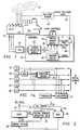
- FIGURE 1there is illustrated an overall block diagram.
- a plant 10is provided that, during the normal operation thereof, releases some emissions 12 containing some level of pollutants.
- the pollutants 12are monitored by a pollutant sensor 14 or by utilization of EPA established reference methods, which sensor 14 is illustrated in phantom, to provide continuous emissions monitoring. This is referred to as a CEM.
- the present inventionprovides a virtual sensor operation wherein the pollutant sensor 14 is only required for initial training of virtual sensor network.
- the pollutant sensor 14is utilized to gather training data to be combined with the control values and sensor values that are available to a Distributed Control System (DCS) 16, generally referred to as the plant information system.
- DCSDistributed Control System
- the DCS 16provides control values associated with control inputs to the system and sensor values to a computer 15.
- the computer 15is comprised of a virtual sensor network 18 that essentially provides a non-linear representation of the plant 10, which non-linear representation is a "learned" representation.
- the virtual sensor network 18is operable to receive run time inputs 20 from a sensor validation system 22.
- the sensor validation system 22is operable to receive actual measured inputs 24 from the plant 10 through the DCS 16. These measured inputs represent measured state variables of the plant in the form of sensor values and also control values that are input to the plant to provide control therefor.
- the various inputs 24are provided as inputs to the virtual sensor network 18 through the DCS 16. However, some of these inputs may be faulty and the sensor validation system 22 is operable to generate an alarm when any of the attached sensors fails and to replace failed sensor values with reconciled sensor values.
- the virtual sensor network 18is operable to receive the inputs 20 and predict plant controls and alarms.
- the virtual sensor network 18can predict what the pollutant levels are that normally would be monitored by the pollutant sensor 14; hence, it provides a virtual sensor.
- the sensor network 18is a network that can be trained with a training system 28.
- the training system 28utilizes as a target the actual pollutant level on a line 13 as measured by the pollutant sensor 14 when it is present, and also the inputs 24 from the plant 10.
- the difference between the predicted pollutant level on a line 17 and the actual pollutant level on line 13generates an error on line 19 that is used by the training system to adjust the stored representation in the virtual sensor module, so as to minimize the error.
- the pollutant sensor 14is a Continuous Emissions Monitor (CEM) that is operable to be temporarily connected to the plant 10 to monitor the level of the pollutants 12. This provides a target to the training system 28.
- the network 18is then trained with both the measured plant sensor and control values, not including the CEM output, and the CEM output when present. This information is utilized to generate a training dataset.
- CEMContinuous Emissions Monitor
- the pollutant sensor 14After training, the pollutant sensor 14 is removed and then the system operates by predicting what the output of the CEM or pollutant sensor 14 would be.
- the virtual sensor network 18then replaces the pollutant sensor 14 and then can be utilized in a control function to predict plant control/alarms to maintain the operation of the plant 10 within acceptable standards.
- the virtual sensor network 18can be used solely to provide an output in place of the pollutant sensor 14 that can be utilized by the operator of the sensor to ensure that all necessary procedures are being followed to ensure that the level of pollutants is within acceptable ranges. For example, if the predicted output from the network 18 exceeded one of the established guidelines or thresholds, the operator would then follow certain prescribed procedures to correct the situation. This would be the case even if the pollutant sensor 14 were present.
- the advantage to thisis that the relatively expensive and difficult to maintain pollutant sensor 14 would not have to be present. Further, a new pollutant sensor 14 or a portable pollutant sensor 14 is periodically utilized to check the operation of a virtual sensor network 18 to ensure that it is operating correctly and that no parameters of the plant have changed such that the prediction is now incorrect or the model no longer represents the plant. In this manner, the system would have to be retrained by using a new set of training data that would be provided by the operation of the connecting the pollutant sensor 14 to the plant 10. This could be the situation wherein some measurement device degraded or the plant itself had physically changed parameters due to capital improvements, age, etc.
- the pollutant sensor 14may be in a situation where it might be removed from the plant 10 for calibration purposes. During this time, the virtual sensor network 18 is then utilized to replace the sensor 14 during the calibration procedure.
- FIG. 1athere is illustrated a block diagram of the operation of the sensor validation system 22.
- a plurality of sensors 27, 29, 31, 33 and 35are illustrated.
- Each of the sensors 27, 29, 31, 33 and 35have an output that is connected to the input of the virtual sensor 18. Additionally, each of the outputs is connected to an evaluation system 37 to determine if the sensor is valid, as will be described hereinbelow.
- a substitute sensor 39which is a predicted sensor value that predicts the output of the faulty sensor utilizing a stored representation of the faulty sensor, which stored representation is a function of the other sensors 27, 29, 31, 33 and 35.
- the substitute sensor 39requires as inputs the outputs of the valid sensors and the predicted output of the substitute sensor. This is illustrated in Figure 1a with the sensor 29 being substituted, with the substitute sensor 39 receiving as inputs the outputs of the sensors 27, 31, 33 and 35 and, in place of the output of the sensor 29, the predicted output of the substitute sensor 39. Further, another sensor could be substituted for with the output of the substitute sensor 39 being an input for the new and additional sensor (not shown).
- FIGURE 2there is illustrated a block diagram for the operation wherein a virtual sensor predictive network 32 is provided which is operable to receive measured plant sensor values s(t) from the plant 10 and also the control values x(t) which are inputs to the plant 10.
- the virtual sensor predictive network 32is operable to output a predicted virtual sensor value o p (t) for input to a multiplexer 34.
- the sensor value from sensor 14is input on the line 36 to the multiplexer 34.
- the multiplexer 34is operable to select either the predicted output of the network 32 or the actual output of the sensor 14 for input to a control system 38.
- the control system 38is operable to generate the input values x(t) to the plant 10.
- the multiplexer 34represents the operation wherein the output of the network 32 is utilized to replace that of the sensor 14.
- a control network 40which receives as an input the control input values x(t) and the sensor values s(t), the sensor values s(t) comprise the measured plant variables such as flow meter measurements, temperature measurements, etc.
- the control net 40is operable to receive a desired output value as one of the inputs.
- the control net 40contains a stored representation of the plant and is operable to output a set of control input values x(t+1) .
- DCSDistributed Control System
- the control network 40is a conventional control network that is trained on a given desired input, and which control network 40 is operable to receive the sensor values and control values and generate the updated control values x(t+1) that are necessary to provide the desired outputs.
- the control network 40is generally comprised of a neural network having associated therewith weights that define the representation that is stored in the neural network. In the embodiment of FIGURE 3, these weights are frozen and were learned by training the control network 40 on a given desired output with a given set of training data for the control values x(t) and the sensor values s(t) .
- a desired outputis provided as one input for selecting between sets of weights.
- the general operation of control netsis described in W.T. Miller, III, R.S. Sutton and P.J. Werbos, "Neural Networks for Control", The MIT Press, 1990.
- FIGURE 4there is illustrated a detailed diagram of a conventional neural network comprised of input nodes 44, hidden nodes 46 and output nodes 48.
- the input nodes 44are comprised of N nodes labelled x 1 ,x 2 ,... x N , which are operable to receive an input vector x(t) comprised of a plurality of inputs, INP1(t), INP2(t), ... INPN(t).
- the output nodes 48are labelled o 1 , o 2 ,... o K , which are operable to generate an output vector o(t) , which is comprised of the output OUT1(t), OUT2(t), ... OUTK(t).
- the input nodes 44are interconnected with the hidden nodes 46, hidden nodes 46 being labelled a 1 , a 2 , ... a n , through an interconnection network where each input node 44 is interconnected with each of the hidden nodes 46.
- Each of the interconnectshas a weight W ij 1 .
- Each of the hidden nodes 46has an output o i with a function g , the output of each of the hidden nodes defined as follows:
- the output of each of the hidden nodes 46is interconnected with substantially all of the output nodes 48 through an interconnect network, each of the interconnects having a weight W jk 2 associated therewith.
- the goalis to minimize the Total-Sum-Square-Error function: The Total-Sum-Square-Error function is minimized by changing the parameters P of the function f . This is done by the back propagation or a gradient descent method in the preferred embodiment on the parameters W jk 2 , W ij 1 ,b 1 j , b 2 k .
- the neural networkis essentially a parameter fitting scheme that can be viewed as a class of statistical algorithms for fitting probability distributions.
- the neural networkcan be viewed as a functional approximator that fits the input-output data with a high-dimensional surface.
- the neural networkutilizes a very simple, almost trivial function (typically sigmoids), in a multi-layer nested structure
- the neural network described aboveis just one example.
- Other types of neural networks that may be utilizedare those using multiple hidden layers, radial basis functions, gaussian bars (as described in U.S. Patent No. 5,113,483, issued May 12, 1992, which is incorporated herein by reference), and any other type of general neural network.
- the neural network utilizedis of the type referred to as a multi-layer perceptron.
- FIGURE 5athere is illustrated a block diagram of a control system for optimization/control of a plant's operation.
- the plant 10has an input for receiving the control values x(t) and an output for providing the actual output y(t) with the sensor values s(t) being associated therewith, these being the internal state variables.
- a plant predictive model 74is developed with a neural network to accurately model the plant in accordance with the function f(x(t),s(t)) to provide an output o p (t) , which represents the predicted output of plant predictive model 74.
- the inputs to the plant model 74are the control values x(t) and the sensor values s(t) .
- the plant model 74is deemed to be a relatively accurate model of the operation of the plant 72.
- an operatorindependently generates a desired output value o d (t) for input to an error generation block 78 that also receives the predicted output o p (t) .
- An erroris generated between the desired and the predicted outputs and input to an inverse plant model 76 which is identical to the neural network representing the plant predictive model 74, with the exception that it is operated by back propagating the error through the original plant model with the weights of the predictive model frozen.
- This back propagation of the error through the networkis similar to an inversion of the network with the output of the plant model 76 representing a ⁇ x(t+1) utilized in a gradient descent operation illustrated by an iterate block 77.
- the value ⁇ x(t+1)is added initially to the input value x(t) and this sum then processed through plant predictive model 74 to provide a new predicted output o p (t) and a new error. This iteration continues until the error is reduced below a predetermined value. The final value is then output as the new predicted control values x(t+1) .
- This new x(t+1) valuecomprises the control values that are required to achieve the desired actual output from the plant 72.
- Thisis input to a control system 73, wherein a new value is presented to the system for input as the control values x(t) .
- the control system 73is operable to receive a generalized control input which can be varied by the distributed control system 73.
- the general terminology for the back propagation of error for control purposesis "Back Propagation-to-Activation" (BPA).
- the method utilized to back propagate the error through the plant model 76is to utilize a local gradient descent through the network from the output to the input with the weights frozen.
- the first stepis to apply the present inputs for both the control values x(t) and the sensor values s(t) into the plant model 74 to generate the predicted output o p (t) .
- the outputis then regenerated from the new x(t), and the gradient descent procedure is iterated.
- the iterate block 77is comprised of a summing junction which is operable to receive the ⁇ x(t+1) input and the output of a multiplexor/ latch block 86.
- the multiplexor/latch block 86is operable to receive both the output of the summing junction 84 for feedback as one of the inputs and the control variable x(t).
- the output of the summing block 84is the sum of the previous value of x(t) plus the new iterative change value ⁇ x(t) . This will then be iteratively summed with the previous value to generate a new iterative value until the error is at a predetermined level. At this point, the output of the summing junction 84 will comprise the new control value x(t+1) .
- Another standard method of optimizationinvolves a random search through the various control values to minimize the square of the difference between the predicted outputs and the desired outputs. This is often referred to as a monte-carlo search.
- This searchworks by making random changes to the control values and feeding these modified control values into the model to get the predicted output. The predicted output is then compared to the desired output and the best set of control values is tracked over the entire random search. Given enough random trials, a set of control values will be obtained that produces a predicted output that closely matches the desired output.
- S. Kirkpatrick, C.D. Gelatt, M.P. Vecchi"Optimization by Simulated Annealing". Science, vol. 220, 671-780 (1983).
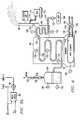
- FIGURE 6there is illustrated a diagrammatic view of a typical plant that may exist at a manufacturing facility.
- the planttypically comprises a boiler 92 which has a firebox 94 disposed at the lower end thereof.
- the boiler 92interfaces with a stack 96 through a preheat chamber 98.
- Many tubes of which tube 100 is typical thereofare operable to run through the chamber 98 and enter the boiler 92.
- the tube 100then passes in a serpentine manner through the boiler 92 to an output pressure vessel 104, which is pressurized.
- the vessel 104is operable to generate steam out of an outlet 106.
- the other end of the tube 100 that enters the chamber 98is connected to a source 108 of the deionized water.
- the wateris passed through the tube 100 to the chamber 98, which picks up heat therein and then into the main boiler 92, where it is heated further. This then passes through to the vessel 104.
- the firebox 94has a heating element 116 associated therewith that is operable to receive gas through a gas line 118 and air through an air line 120. The mixture of the gas and the air allows the heating element 116 to generate heat in the firebox 94 and heat up the water in the tube 100 within the boiler 92.
- the tube 100when it exits the source 108 with the deionized water at the source, has the flow thereof measured by the flow meter 122.
- a valve 124allows control of the flow of fluid from the source 108 into the chamber 98.
- Two temperature sensors 126 and 128are provided at different locations along the tube 100 within the chamber 90 to provide temperature measurements therefor. Additionally, temperature sensors 130, 132 and 134 are provided along the tube 100 at various locations within the main boiler 92.
- a temperature sensor 136is provided for the firebox 94.
- the level of the fluid within the pressure vessel 104is measured by a level meter 142 and the pressure therein is measured by a pressure meter 146.
- a flow meter 150is provided for measuring the flow of steam out of the pressure vessel and a control valve 152 provides control of the steam exiting the pressure vessel 104.
- the heater element 116is controlled with a valve 158 on the gas line, which has the flow thereof measured by a flow meter 160.
- the flow meter on the air line 120is measured by a flow meter 162.
- a damper 163 in the stack 96is utilized to control air flow through the firebox 94.
- the sensor values s(t) of the plantare provided by the various temperature and flow measurement devices.
- the control valuesin the form of the various valves and damper positions provide the control values to the plant. Therefore, an operator can control the operation of the plant by controlling the various flow meters and other control values, some of which are not illustrated.
- the remaining inputs that are necessary in order to provide adequate control of the plant for the purpose of continuous emissions monitoringare the NOx levels. These are provided by the virtual sensor network 18 of FIGURE 1. However, as described above, periodically a portable unit 170, having disposed thereon a CEM 172, is connected via a duct 174 to the stack 96 to measure the amount of NOx in the output emissions to the air.
- the CEM 172then generates a report as to the level of the NOx. If this level is within acceptable standards, then this is merely reported. However, if the level is outside of acceptable limits, this is reported to the plant operator and either changes are made or the plant is shut down. Additionally, the information generated by the CEM 172 is generated on a time base and this comprises training data. This training data, since it is on a common time base, can then be combined or merged with data associated with the sensor values and the control values, which are also on a time base, to provide new training data for the virtual sensor network 18. This can be utilized by the training system 20 to retrain the virtual sensor network 18, if necessary.
- FIGURE 7there is illustrated a block diagram of the preferred embodiment for the sensor validation system 22.
- the sensor validation system 22To ensure that the overall inputs x(t) to the network 18 are "valid", it is necessary to perform some type of comparison with expected or predicted values. If it is suspected that the generated values are not accurate, then an alarm is generated to advise the plant operator or the control system of the need to calibrate the sensor or to repair the sensor, and an estimated or predicted value for that sensor value is substituted for the actual measured value of the sensor.
- an auto associative predictive neural network 180is provided which is a network having an input layer for receiving select ones of the inputs x(t) on an input 182.
- an input layerfor receiving select ones of the inputs x(t) on an input 182.
- only certain ones of the actual sensor valuesare necessary as inputs to the virtual sensor network 18 in order to provide an accurate prediction of the NOx levels that would generally be provided by the pollutant sensor 14. These are determined by performing a sensitivity analysis. This is described in U.S. patent application Serial No. 056, 197, filed April 30, 1993 and entitled “Method and Apparatus for Determining the Sensitivity of Inputs to a Neural Network on Output Parameters" (Atty. Dkt. No.
- the actual inputs x(t)are input to a multiplexer 186 which is operable to select between the predicted inputs x p (t) output by the network 180, which is a predicted output, and the actual inputs x(t).
- a first cycleoccurs when the multiplexer selects the actual inputs x(t) .
- the predicted inputs x p (t)are then input to a subtraction circuit 188 to determine the difference between x(t) and x p (t) .
- This differenceis input to comparator 190 for comparison with thresholds stored in a threshold memory 192.
- the one of the actual inputs to the network 180 having associated therewith the largest error as compared to the acceptable thresholdis then connected to the associated predicted output of the network 180.
- the actual inputs x(t) with the substituted or reconnected inputis then again cycled through the auto associative predictive network 180.
- the difference between the actual and the predicted valuesare again determined, compared with the thresholds, and the one of the actual inputs having the largest error is reconnected to the associated predicted input by the multiplexer 186.
- the predicted values from the network 180are input to a multiplexer 196, and the multiplexer 196 selecting for output therefrom the actual values that were determined to be acceptable and the predicted values as a substitute for the actual values that were determined to be unacceptable.
- the predicted valuesare generated by running the network with the determined unacceptable actual values replaced with the associated predicted values by the multiplexor 186.
- the output of the multiplexor 196is then input to the virtual sensor network 18.
- the predicted input values output by the auto associative predictive network 180can be provided as the input to the virtual sensor network 18. This would then not require the multiplexer 196 and, in fact, the auto associative predictive network 180 can continually monitor and replace ones of the sensor inputs that are determined to be invalid.
- FIGURE 8there is illustrated a diagrammatic view of the auto associative predictive network 180.
- the networkis comprised of an input layer of nodes 198 and an output layer of nodes 200.
- there is a single node for each of the predicted output variables x p (t)such that there are outputs x 1 p (t), x 2 p (t) ... x n p (t).
- the input layer of nodes 198is mapped through to the output layer of nodes 200 through a hidden layer of nodes 202.
- the hidden layer of nodes 202has a plurality of interconnections with each of the nodes in the input layer of nodes and each of the output layer of nodes 200. Each of these interconnections is weighted. Further, the number of nodes in the hidden layer of nodes 202 is less than the number of nodes in either the input layer 198 or the output layer 200. This is therefore referred to as a bowtie network.
- the network 180can be trained via a back propagation training technique. This is described in D.E. Rumelhart, G.E. Hinton and R.J. Williams, "Learning Internal Representations by Propagations" in D.E. Rumelhart and J.L. McClelland, Parallel Distributive Processing, Vol. 1, 1986.
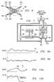
- FIGUREs 9a and 9bthere are illustrated two plots depicting operation of the sensor validation system 22.
- the actual inputsare represented by X A and the predicted input is represented by X p . It can be seen that the predicted input does not exactly follow the actual input, it being noted that the actual input is actually the input to the overall system. The difference between the actual and the predicted input values is illustrated in FIGURE 9b.
- FIGUREs 10a and 10bthere is illustrated corresponding plots to those of FIGUREs 9a and 9b with the exception that the sensor generating the actual input fails. It can be seen that up to a point 204 on the curve X a , the predicted and actual sensor values track fairly well with minimal error. However, at the point 204 the error increases dramatically, indicating that the sensor no longer provides an value that corresponds to the predicted value. This is illustrated in FIGURE 10b, wherein the error increases. When the difference between X A and X p is greater than a threshold, this indicates an invalid reading. However, as noted above, only the one of the sensors having the highest error above the threshold will be selected as replacement value by the multiplexer 86 for the next cycle.
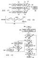
- FIGURE 11there is illustrated a flowchart depicting the overall operation of the system.
- the flowchartis initiated at a start block 208 and then flows to a decision block 210.
- Decision block 210determines whether the remote CEM has been installed. If so, the program then flows to a function block 212 to measure the NOx levels with the remote CEM.
- the programthen flows to a decision block 214 to determine whether the measured NOx values, measured in function block 212, are acceptable. If not, this indicates that the virtual sensor network 18 is out of spec and that the system has either changed or the network no longer represents the system.
- the programwill then flow along an "N" path to a function block 216 to measure the system variables and then to a function block 218 to generate a training database.
- a training databaseessentially utilizes the system variables that are measured along the same time base as the measured NOx levels.
- the remote CEMwill be placed adjacent to the manufacturing facility and the pollutants measured for a predetermined amount of time, which can be measured in hours, days or weeks.
- the plant facilityitself is measuring the plant variables. These are also placed on a time base and stored.
- a training databasecan be provided for training the virtual sensor network 18. This time merging operation is described in U.S. Patent Application Serial No. 980,664, filed November 24, 1993 and entitled "Method and Apparatus for Operating a Neural Network with Missing and/or Incomplete Data" (Atty. Dkt. No. PAVI-20,965).
- the virtual sensor network 18is trained, as indicated by a function block 220. This essentially generates weights, which can then be substituted for the neural network weights in the virtual sensor network 18.
- the programthen flows to a function block 222 to substitute new weights in the virtual sensor network 18. Thereafter, the program flows to a main operating portion of the program, which is initiated at a function block 224 to validate the sensors.
- the programwould flow from the decision block 218 along a "Y" path to the input of function block 224 to bypass the training step. Additionally, if the remote CEM is not present, the program would flow along an "N" path from the decision block 210 to the input of the sensor validation block 224.
- the sensor validation block 224validates the sensors and, if one is found invalid, it substitutes a predicted value for that invalid sensor.
- the programwould then flow to a function block 226 to determine if certain sensors needed to be replaced by predicted values. If so, the program would flow along a "Y" path to replace the invalid sensors with the predicted sensor value.
- the programwould then flow to a function block 232 to predict the pollutant value and then to a function block 232 to control the plant. The program would then flow back to a decision block 210. If it were determined that sensors did not need to be replaced by their predicted values, the program would flow along an "N" path from the decision block 226 to the input of function block 230.
- FIGURE 12there is illustrated a function block depicting the operation of the sensor validation.
- the programis initiated at a start block 240 and then flows to a function block 242 to input the various sensor readings.
- the programthen flows to a function block 244 to run the sensor validation model and then to a decision block 246 to compare the predicted input values with the thresholds and generate an error signal when any of the predicted input values exceed the thresholds for that given variable, it being noted that there can be a threshold for each variable as to what constitutes an error for that sensor value.
- the programflows to a function block 248 to replace the largest input error with the mean value for that input. An alarm is generated at this point to warn of the failed sensor.
- the programwill then flow back the input of a function block 244.
- the programwill flow from a decision block 246 to a function block 250 to replace all detected errors with predicted sensor values and then to a function block 252 to output reconciled sensor values. The program will then flow to a return block 254.
- FIGURE 13there is illustrated an embodiment wherein the virtual sensor is utilized in conjunction with an internal combustion engine 260.
- the internal combustion engine 260receives air on an intake port 262. This is input to a butterfly valve 264 which is basically the throttle valve that is controlled by the foot pedal on an automobile. The butterfly valve then feeds the restricted airflow to an intake manifold 266, which is input to the internal combustion engine 260.
- the fuel injection valve 268is operable to inject fuel into the intake manifold 266 in a regulated amount, which is determined by a number of factors, this being conventional.
- the internal combustion engine 260exhausts the combustion ingredients into an exhaust manifold 270.
- the exhaust manifold 270is connected to an exhaust pipe 272 which is connected to the input of a catalytic converter 274.
- the catalytic converter 274then interfaces with the tail pipe 276 to output the combustion gases.
- the exhaust manifold 270is connected through a pipe 278 to an emissions gas recirculation valve (EGR) 280.
- the EGR 280is interfaced with the intake manifold 266 through a pipe 282.
- the EGR 280is a conventional pollution control device that is operable to bleed off a small portion of the exhaust gases from the exhaust manifold 270 back into the intake manifold for recombustion thereof.
- EGR valvestypically operate at higher RPMs of the engine, as the recirculation of the exhaust gases at low RPMs causes the engine to idle roughly.
- an oxygen sensor 286is disposed in the exhaust manifold 270.
- the oxygen sensor 270basically provides for measurement of the exhaust gas ingredient concentration, typically oxygen, that exists in the exhaust manifold 270.
- These type of sensorsare utilized for air-fuel ratio control systems.
- the sensoris input to a central processing unit (CPU) 288 which controls the operation of the fuel injectors through a line 290 and the fuel supply thereto. Again, these are conventional systems.
- the CPU 288is operable to monitor a large number of parameters regarding the internal combustion engine, which parameters require some type of sensors.
- the operation of the ignitioni.e., spark advance, timing, etc.
- the manifold temperatureis provided by a manifold temperature sensor (TM) 294 and the cylinder temperature is provided by a cylinder temperature sensor (TCYL) 296.
- TMmanifold temperature sensor
- TTYLcylinder temperature sensor
- the sensors 294 and 296allow a temperature measurement to be made of each cylinder and the overall manifold.
- the back pressure in the exhaust pipe 270is provided by a pressure sensor (PEX) 298 and the pressure in the intake manifold is provided by a pressure sensor (PMAN) 300.
- PEXpressure sensor
- PMANpressure sensor
- the pressure sensor 300measures a vacuum for a conventional engine, which could be a positive pressure when the system is operated in conjunction with a turbocharger.
- the intake manifold temperatureis provided by a temperature sensor (TA) 302, which is connected to the intake manifold 266.
- the position of the butterfly valve 264is provided by a position sensor ( ⁇ th) 306.
- the temperature of the catalytic converteris measured by a temperature sensor (TCAT) 308.
- the CPU 288incorporates the full sensor system as described hereinabove and is operable to predict the emissions emitted by the internal combustion engine which, in the preferred embodiment, are primarily NO X , and either output this information in the form of a display, store it as a history or utilize it to control the operation of the engine.
- an emissions control system 308is provided, which is operable to control certain parameters of the system.
- one parameter that could be controlledis the internal threshold to the CPU 288 that determines the air-fuel ratio.
- the oxygen sensor 286operates on a threshold such that when it is above the threshold, the air-fuel mixture is changed in one direction and, when the oxygen sensor falls below the threshold, the air-fuel ratio is changed in the other direction.
- the thresholdBy changing the threshold, the average air-fuel ratio will be changed, and therefore, the actual emissions output can also be changed. This will be described in more detail hereinbelow.
- thresholdscan be loaded into the CPU 288, which thresholds can be selected in accordance with predetermined criteria. Additionally, a history can be provided of the vehicle as to the emissions generated by the engine and this stored for downloading at a later time for the purpose of monitoring the operation of the vehicle and the associated engine.
- the modelSince the emissions prediction is achieved utilizing a model of the system which utilizes the sensor outputs as inputs to provide the predicted output, the model must be initially trained. This initial training operation can be done on a "generic" engine with a "standard” emissions monitor and the then the model parameters downloaded to a standard integrated circuit which is utilized for all vehicles. This assumes that the model trained on the generic system holds true with respect to all subsequent systems and the manufacturing tolerances associated therewith. However, even if the generic model does provide a true representation of all engines manufactured for a given type of engine in combination with a standard emissions monitor, the parameters of the engine will change over time. It may therefore be necessary to update the training. This can be achieved in two ways.
- the emissionscan be measured with an emissions sensor that is external to the vehicle and not an integral part thereof and this compared to the predicted emissions output. If an error exists that is too large, the system then can be retrained. The retraining can either be a complete retraining of the model or merely an update of the training weights. In any event, this requires an actual emissions sensor to be utilized.
- the modelcan have a "bias" applied thereto to provide a slight offset. This also requires actual emissions to be monitored. The actual values are necessary to know how to adjust the bias.
- FIGURE 14there is illustrated a block diagram of a system wherein an external emissions sensor 310 is utilized for training.
- the internal combustion engineis represented by a block 312, which receives inputs on a line 314 and provides measured outputs or state variables s(t) on lines 316, these comprising the inputs to the model.
- state variablesare first processed by sensor validation module 318, which was described hereinabove, and which is operable to substitute a predicted sensor output in the event of a failure of one of the sensors. This is described hereinabove with reference to FIGUREs 7 and 8.
- the validated state variables s(t)'are output on lines 320 to a predictive model processor 322.
- the predictive model processor 322is operable to interface with the memory 324 for storing model parameters to process the parameters and provide a predicted output e(t) on a line 326. Additionally, the predictive model processor 322 is operable to store a time history of the predicted output in a memory 328.
- the model that is storedis a representation of the combined engine and emissions sensor. Therefore, the model will have associated therewith all aspects of both the engine and the emissions sensor. Even if the emissions sensor is inaccurate, the model is only as good as the sensor, but this inaccuracy must be incorporated into the model. This is important in that regulatory bodies require that the output measurement comply to their standards, which standards are defined by their equipment. If, for example, the emissions sensor that complied with their standards were in fact inaccurate, it would be important to predict an output with these inaccuracies. To correct these inaccuracies would not be acceptable. Therefore, the model is determined utilizing as part of the system the actual hardware sensor, which is removed during operation of the engine.
- the external emissions sensor 310is connected to the output of the internal combustion engine, which comprises a line 330 labelled y(t) .
- the emissions sensor 310is connected to the output to provide an actual output value ofthe emissions on a line 332.
- This generates an error Ewhich is input to a comparator 336.
- the comparator 336compares the error E with a predetermined threshold and then outputs a "Train" signal on a line 340. If the error exceeds the threshold, a training operation is initiated.
- the predictive model processor 322then enters into a training mode utilizing the actual emissions sensor outputs on a line 344 and the state variable inputs 320 to retrain the model. These parameters are then input to the memory 324. After training, the system will again be validated by comparing the operation of the internal combustion engine and the emissions output thereby with the predicted emissions output. Once the error has been minimized, i.e., reduced below the threshold, the system will be "validated".
- the predictive model processor 320can train the network by two methods. In the first method, it can completely regenerate model parameters from scratch utilizing a typical training algorithm. In the second method, it can merely update the model parameters, i.e., provide a minor adjustment thereto in order to reduce the error.
- the retraining processor 346is operable to receive on the input thereof the output state variables from the internal combustion engine 312 on lines 348, the actual output emissions sensor on the line 332 and the error output of the difference device 334. The retraining processor 346 then determines whether retraining is necessary, and if so, the retraining processor 346 will either update the model parameters or generate a new set of model parameters. During an update process, the old model parameters from the memory 324 are uploaded and adjusted and then downloaded back to the memory 324. In the complete training process, completely new model parameters are generated and then downloaded to the memory 324. Of course, after retraining or any modification of the model parameters 324, the system is again checked.
- backpropagationIn the training of the network, one technique that can be utilized is backpropagation, as described in D.E. Rumelhart, G.E. Hinton, and R.J. Williams, "Learning Internal Representations by Error Propagation” in D.E. Rumelhart & J.L. McClelland, Parallel Distributed Processing, Vol . 1, 1986.
- this techniqueas applied to a neural network, training is achieved by minimizing the Least Mean Square Errors with backpropagation. This utilizes the technique of steepest descents, wherein the weights W ij of a neural network and the parameters associated with the activation function are varied to minimize the error function.
- This backpropagation techniqueis essentially a common, non-linear least squares algorithm.
- a neural networkIn addition to backpropagation, other techniques for training a neural network can be utilized, such as radial basis functions or Gaussian bars. Further, it is not necessary to utilize a neural network to provide a stored representation of the system. A fuzzy system (which is very similar to a radial basis function network) can also be utilized.
- FIGURE 16there is illustrated a block diagram depicting the runtime operation of the internal combustion engine 312.
- the system of FIGURE 16utilizes a control network 350 which is operable to receive the control input x(t) on line 314, the validated sensor outputs s(t)' on lines 320 and output updated control inputs x(t+1) on a line 352.
- the control network 350is described above with reference to FIGURE 5a and can actually incorporate the model that is implemented by the predicted model processor.
- a desired or target emissions levelis input thereto.
- the line 352is input to an engine control system 354 which is operable to effect the various controls on the internal combustion engine. Any one of the controls can be manipulated to control the emissions within predetermined guidelines, these controls associated with controlling he air-fuel ratio.
- the overall systemis controlled by a runtime operating system 354 which is operable to receive the predicted output on the line 326 from the predictive model processor 322 and also receive the output of the sensor validation module 318 indicating which, if any, of the sensors have been determined to be in error. This information, in addition to the predicted emissions value output on line 326 is then utilized by the runtime operating system to either store it in the memory 328 associated with the historical information or make various decisions as to what should be done with respect to the predicted emissions information.
- Runtime thresholdsare prestored in a memory 356 and are utilized by the runtime operating system for comparison with the predicted emissions. If the predicted emissions exceed the selected one of the thresholds, some action must be taken. For example, emissions may be acceptable at one threshold in one area of the country and unacceptable in another area of the country. Further, the predicted emissions levels may also have an acceptability that is a function of other parameters, such as temperature and humidity.
- the runtime thresholdscould be selected as a function of atmospheric conditions or other criteria. However, in the preferred embodiment, it is anticipated that thresholds will be selected as a function of the locale that the engine is disposed in. Further, they could even be selected as a function of the time of day.
- a user input 358is utilized to select the thresholds or input thresholds via an input/output circuit 360.
- the input/output circuit 360is operable to interface with a display 360 and also with a communication system 362.
- the display 360can be, for example, a warning light. Further, it could be some type of display that actually outputs an analog value in the form a "gas gauge" for viewing by the driver. This would allow the driver to actually view the emissions levels as a function of his driving conditions, etc.
- the communications system 362is provided such that industrial engines at remote sites can be controlled on a periodic basis to download the stored history information in memory 328 to a central station.
- FIGURE 17there is illustrated an overall view of the communication system.
- a plurality of engines referred to as plants 370are disposed at remote locations, each having a virtual emissions monitor 372 associated therewith and each having a communications device 374 associated therewith.
- each of the communication devices 374is operable to transmit information over a wireless communication path via an antenna 376, which antenna 376 can operate in both a receive mode and a transmit mode.
- the antennas 376are operable to communicate with an antenna 378 on a command station 380.
- the protocol utilized for the transmissioncan be any type of conventional protocol. Although a wireless system is illustrated, it should be understood that a fixed wire system could be utilized.
- the networkcould have the parameters thereof offset or a bias adjust applied thereto.
- the networkcould have the parameters thereof offset or a bias adjust applied thereto.
- FIGURE 18a situation could occur wherein the average of the plant output drifts by some amount.
- a first principles modelcould be utilized.
- First principle modelsare well-known and rely upon the fact that there are only a small number of controls that can be tuned or adjusted on the internal combustion engine. Typically, this tuning or control takes the form of adjusting parameters, i.e., coefficients in the model to minimize the error that exists between the model output and the actual plant or engine output.
- This procedureis completely analogous to training a neural network model. The differences between the two training operations occur in the method that the parameters appear in the model and perhaps the way in which they are adjusted.
- First principle modelsare often simpler than neural network models in that they are often linear and have fewer adjustment parameters.
- FIGURE 19there is illustrated a flowchart depicting the overall runtime control operation.
- the programwould be initiated at a start block 386 and then proceeds to a function block 388 to compare the expected emissions value to an internal runtime threshold, it being remembered that these thresholds can be selected by the user for a particular circumstance.
- the programthen flows to a decision block 390 to determine if the expected or predicted emissions exceed the threshold. If so, this indicates that some control operation or failure mechanism must be performed.
- the programwould flow to a decision block 392 to determine if a control operation is present. If so, the program would flow along a "Y" path to a function block 394 to adjust the controls in accordance with the predetermined control operation which could utilize the first principles operation as described above, or a control network.
- the programwould then flow to a decision block 396 to determine if it is possible to effect an appropriate control. In order to determine this, maximum limits are set within the operating parameters of the engine by which the controls can be modified to reduce emissions. If these control limits are exceeded, the engine operation will deteriorate, even though the emissions was appropriate. If the maximum control limit has been exceeded, the program would flow along a "Y" path to a function block 398 to set the default settings for the emissions control parameters and then to a function block 400 to store the history. If the maximum control limit had not been exceeded the controls would be accepted and the program would flow along an "N" path from decision block 396 to the function block 400. If no controls were available, the program would also flow to the function block 400 from the decision block 392 along the "N" path thereof.
- the programwould flow to a decision block 402 to determine if an alarm operation were present. This could occur in the event that the comparison made at decision block 390 required an alarm to be set or if the presence of the default setting in the function block 398 required an alarm to be set. If an alarm is to be set, the program would flow along the "Y" path from decision block 402 to a function block 404 to set the alarm, this possibly being a light on the dashboard or an audible alarm. Further, this could be the existence of an alarm communication to a central station requiring a maintenance check. The program would then flow to a return block 406.
- the programwould flow from the decision block 402 along the "N" path to the return block 406. Similarly, if the predicted emissions did not exceed the threshold, the program would flow to the return block 406 along the "N" path from the decision block 390.
- FIGURE 20there is illustrated a flowchart depicting the training operation.
- the programis initiated at a start block 410 and then proceeds to a function block 412 to measure the actual emissions.
- the programthen flows to a function block 414 to compare the measured actual emissions to the expected or predicted value output by the virtual sensor.
- the programthen flows to a decision bloc 416 to determine if the difference between the measured actual emissions and the predicted value exceed the threshold. If so, the program would flow along a "Y" path to a decision block 418 to determine if a training operation is to be performed. If not, the program would flow along an "N" path to a function block 420 to update a record database and then to a return block 422. Similarly, if the error did not exceed the threshold, the program would flow from the decision block 416 along the "N" path to the function block 420.
- the programwould flow from the decision block 418 along a "Y" path to a decision block 424 to determine if a full training operation is to be performed. If yes, the program would flow along a "Y" path to a function block 426 to retrain a complete model and then to a function block 428 to download the model parameters back to the memory associated with the model parameters. The program will then flow to a return block 430. If a full training operation were not to be performed, i.e., a partial training operation only, the program would then flow along an "N" path from decision block 424 to a function block 432 to upload the model parameters that were in the system and then adjust these model parameters as indicated by a function block 434. After adjustment, the program would flow to the input of the function block 428 to download the model parameters. It should be understood that the training operation can be an on-board operation utilizing the model processor or an off-board operation utilizing an external processor.
- a system for predicting emissions in order to obviate the need for an actual emissions sensor on a reciprocating engineutilizes a predictive model that is trained on various sensor outputs from the reciprocating engine with a target output of the actual emissions taken during generation of the training data set. Once trained, the system can operate without the actual emissions sensor, but represents the actual output of the emissions sensor. Periodically, the model can be checked to determine if the predicted value has deviated more than a predetermined amount from an actual measurement by performing an actual measurement with an external emissions sensor. If the measurement has deviated, the system can be indicated as out of spec or the network can be retrained.
Landscapes
- Engineering & Computer Science (AREA)
- Physics & Mathematics (AREA)
- General Physics & Mathematics (AREA)
- Artificial Intelligence (AREA)
- Automation & Control Theory (AREA)
- Health & Medical Sciences (AREA)
- Evolutionary Computation (AREA)
- Chemical & Material Sciences (AREA)
- Software Systems (AREA)
- Medical Informatics (AREA)
- Computer Vision & Pattern Recognition (AREA)
- Combustion & Propulsion (AREA)
- Life Sciences & Earth Sciences (AREA)
- Immunology (AREA)
- Medicinal Chemistry (AREA)
- Analytical Chemistry (AREA)
- Biochemistry (AREA)
- General Health & Medical Sciences (AREA)
- Food Science & Technology (AREA)
- Pathology (AREA)
- Mathematical Physics (AREA)
- Human Computer Interaction (AREA)
- Mechanical Engineering (AREA)
- General Engineering & Computer Science (AREA)
- Testing And Monitoring For Control Systems (AREA)
- Feedback Control In General (AREA)
- Alarm Systems (AREA)
- Measuring Pulse, Heart Rate, Blood Pressure Or Blood Flow (AREA)
- Testing Of Engines (AREA)
- Exhaust Gas After Treatment (AREA)
- Electrical Control Of Air Or Fuel Supplied To Internal-Combustion Engine (AREA)
- Combined Controls Of Internal Combustion Engines (AREA)
- Testing Or Calibration Of Command Recording Devices (AREA)
- Treating Waste Gases (AREA)
- Control Of Non-Electrical Variables (AREA)
- Superstructure Of Vehicle (AREA)
- Fittings On The Vehicle Exterior For Carrying Loads, And Devices For Holding Or Mounting Articles (AREA)
- Cooling, Air Intake And Gas Exhaust, And Fuel Tank Arrangements In Propulsion Units (AREA)
Description
- The present invention pertains in general to emissions monitoring systems, andmore particularly, to a system that replaces the continuous emissions monitor on areciprocating engine with a virtual sensor.
- As public awareness increases with respect to the environment, industry isrequired to make significant changes. Although industry is somewhat responsive topublic opinion, government regulatory bodies are typically brought in to ensure thatpublic needs are met. In order to do this, government sets up regulatory arms of alreadyexisting branches of entities such as the Environmental Protection Agency. These armsare given the task of putting in place policies regarding toxic waste, emissions, etc., thatmay effect the environment. Further, these regulatory bodies are also given the task ofenforcing these regulations. One particular area that has received a great deal ofattention in recent years is that of monitoring emissions of noxious gases being placedinto the atmosphere by manufacturing facilities.
- Typically, the technique for ensuring that noxious gases are being correctlymonitored has been to implement Continuous Emissions Monitoring systems (CEM).These systems are utilized to monitor the amount of emissions such as Sulfur Dioxide(SO2), Nitrogen Oxides (NOx), Carbon Monoxide (CO), Total reduced Sulfur (TRS),opacity, Volatile Organic Carbon (VOC), and hazardous substances of all sorts. Theclassical way of monitoring these emissions is to install a Continuous Emissions Monitor(CEM) in the plant on each emissions point source. Regulatory Agencies provide foreach plant guidelines as to how the output is to be regulated, i.e., define the acceptablelimit of the emissions. With respect to a reciprocating engine, the EPA has set guidelinesas to the performance of the engine. Once manufactured, the engine is expected to meetthese guidelines over the life of the engine, assuming that it is properly maintained.However, new regulations are being implemented that require some type of continuousmonitoring to be implemented with periodic checkups to ensure that the monitor isoperating correctly.
- The classic CEM is composed of either an in situ analyzer installed directly in thestack, or the exhaust pipe of the reciprocating engine, or an extractive system whichextracts a gas sample and conveys it to an analyzer at grade level. However, thesesensors are quite expensive, difficult to maintain, and difficult to keep properly calibrated. As such, the regulations that deal with a CEM system require the sensors tobe calibrated frequently, which calibration procedure can take a number of hours, due tothe complexity thereof. Regulations allow a maximum downtime often percent forcalibration. If a unit remains in operation greater than ten percent of the time with theCEM down, the emissions level is considered by the Regulators to be at maximalpotential level. This results in out-of-compliance operation. Most manufactures willshut down operation rather than face the high penalties of such occurrence. One of thereasons for this is that the operation of the plant relative to the monitoring of the NOxemissions must be "truly continuous" such that no leeway is provided for faulty sensors,sensors that have fallen out of calibration, etc. One solution to this has been to utilizeredundant sensors, which is a very expensive solution. Therefore, there exists a need toprovide a system that does not require the presence of a sensor while still ensuring thatthe output of the plant is within tolerances relative to noxious emissions.
- The present invention disclosed and claimed herein comprises a method formonitoring emissions in an individual internal combustion engine that emits noxious pollutants andhas associated therewith a plurality of sensors for measuring select parameters of theengine operation, these measured parameters provided as sensor output values. Apredictive model is provided in which a stored representation of the individual engine combinedwith an external emissions monitor is represented. The predictive model is operable tooutput a predicted emissions value corresponding to the output of the external emissionsmonitor when attached to the individual engine, with the inputs to the predictive modelcorresponding to select ones of the sensor output values. The select ones of the sensoroutput values are then input to the predictive model and a prediction is provided of thenoxious pollutants during operation of the individual engine without the requirement of the externalemissions monitor being connected to the individual engine. This is achieved during runtimewithout a runtime monitor for the emissions.
- In another aspect of the present invention, the operation of the predictive modelis verified by attaching an external emissions monitor to the engine to measure thenoxious pollutants output thereby. The measured output is then compared with thepredicted output. If the actual and predicted values differ by more than a predeterminedamount, the stored representation is adjusted. The stored representation is generatedinitially by training the predictive model on a training set of data that comprises as inputdata the actual sensor output values and as target output data the actual measuredemissions output of the external emissions monitor. In one method of adjusting thestored representation, the predictive model is retrained to complete a new storedrepresentation on a new set of training data. In another method, the predicted emissionsvalue is merely offset on the output of the predictive model such that the averagedifference between the offset predicted emissions value and the actual measuredemissions value is less than a predetermined difference.
- In yet another aspect of the present invention, the predicted emissions valueoutput by the predictive network is compared with an internal threshold value. When the predictive emissions value exceeds the internal threshold value, an alarm is generated. Inone embodiment, this alarm is a light. The threshold value can be selected from aplurality of stored threshold values, which threshold value is selected from the pluralityof stored threshold values in accordance with predetermined criteria.
- In a further aspect of the present invention, a control system is provided formodifying the operating parameters of the engine to adjust the output noxious pollutants.An emissions control system is provided which operates in response to receiving thepredicted emissions value output by the predictive model and comparing it with a desiredoutput level. The difference between the two levels is minimized by the control system.
- For a more complete understanding of the present invention and the advantagesthereof, reference is now made to the following description taken in conjunction with theaccompanying drawings in which:
- FIGURE 1 illustrates an overall block diagram of the virtual sensor,
- FIGURE 1a illustrates a diagrammatic view of the sensor validation system;
- FIGURE 2 illustrates a block diagram of the relation of the virtual sensor and thecontrol system;
- FIGURE 3 illustrates an embodiment utilizing a single control network;
- FIGURE 4 illustrates a diagrammatic view of a conventional neural network;
- FIGURE 5a illustrates a more detailed block diagram of the control network;
- FIGURE 5b illustrates a detail of the iterate operation of FIGURE 5a;
- FIGURE 6 illustrates a detail of a typical plant, a boiler for a steam generationfacility;
- FIGURE 7 illustrates a block diagram of the sensor validation network;
- FIGURE 8 illustrates a diagrammatic view of the auto associative predictivenetwork utilized in the system of FIGURE 7;
- FIGUREs 9a and 9b illustrate plots of predicted versus actual pollutant sensorvalues and the difference therebetween;
- FIGUREs 10a and 10b illustrate the plots of FIGUREs 9a and 9b, respectively,wherein one of the sensors is faulty;
- FIGURE 11 illustrates a flowchart for operating the overall system;
- FIGURE 12 illustrates a flowchart for the sensor validation operation;
- FIGURE 13 illustrates the preferred embodiment of the present inventionwherein the virtual sensor is utilized in conjunction with an internal combustion engine;
- FIGURE 14 illustrates a block diagram of a system wherein an external emissionssensor is utilized for training;
- FIGURE 15 illustrates an alternate method wherein the retraining operation isdone external to the system with a retraining processor;
- FIGURE 16 illustrates a block diagram depicting the runtime operation of theinternal combustion engine;
- FIGURE 17 illustrates an overall view of the communication system;
- FIGURE 18 illustrates a plot of the actual emissions output measured by anexternal emissions monitor and the predicted output from the virtual sensor;
- FIGURE 19 illustrates a flowchart depicting the overall runtime controloperation; and
- FIGURE 20 illustrates a flowchart depicting the training operation.
- Referring now to FIGURE 1, there is illustrated an overall block diagram.A
plant 10 is provided that, during the normal operationthereof, releases someemissions 12 containing some level of pollutants. Thepollutants 12 are monitored by apollutant sensor 14 or by utilization of EPA established referencemethods, whichsensor 14 is illustrated in phantom, to provide continuous emissionsmonitoring. This is referred to as a CEM. As will be described hereinbelow, the presentinvention provides a virtual sensor operation wherein thepollutant sensor 14 is onlyrequired for initial training of virtual sensor network. Thepollutant sensor 14 is utilizedto gather training data to be combined with the control values and sensor values that areavailable to a Distributed Control System (DCS) 16, generally referred to as the plantinformation system. TheDCS 16 provides control values associated with control inputsto the system and sensor values to acomputer 15. Thecomputer 15 is comprised of avirtual sensor network 18 that essentially provides a non-linear representation of theplant 10, which non-linear representation is a "learned" representation. Thevirtualsensor network 18 is operable to receiverun time inputs 20 from asensor validationsystem 22. Thesensor validation system 22 is operable to receive actual measuredinputs 24 from theplant 10 through theDCS 16. These measured inputs representmeasured state variables of the plant in the form of sensor values and also control valuesthat are input to the plant to provide control therefor. As will be described hereinbelow,thevarious inputs 24 are provided as inputs to thevirtual sensor network 18 through theDCS 16. However, some of these inputs may be faulty and thesensor validation system 22 is operable to generate an alarm when any of the attached sensors fails and to replacefailed sensor values with reconciled sensor values. - The
virtual sensor network 18 is operable to receive theinputs 20 and predictplant controls and alarms. Thevirtual sensor network 18 can predict what the pollutantlevels are that normally would be monitored by thepollutant sensor 14; hence, itprovides a virtual sensor. Thesensor network 18 is a network that can be trained with atraining system 28. Thetraining system 28 utilizes as a target the actual pollutant level on aline 13 as measured by thepollutant sensor 14 when it is present, and also theinputs 24 from theplant 10. The difference between the predicted pollutant level on aline 17and the actual pollutant level online 13 generates an error online 19 that is used by thetraining system to adjust the stored representation in the virtual sensor module, so as tominimize the error. In operation, as will be described in more detail hereinbelow, thepollutant sensor 14 is a Continuous Emissions Monitor (CEM) that is operable to betemporarily connected to theplant 10 to monitor the level of thepollutants 12. Thisprovides a target to thetraining system 28. Thenetwork 18 is then trained with both themeasured plant sensor and control values, not including the CEM output, and the CEMoutput when present. This information is utilized to generate a training dataset. - After training, the
pollutant sensor 14 is removed and then the system operates bypredicting what the output of the CEM orpollutant sensor 14 would be. Thevirtualsensor network 18 then replaces thepollutant sensor 14 and then can be utilized in acontrol function to predict plant control/alarms to maintain the operation of theplant 10within acceptable standards. Further, thevirtual sensor network 18 can be used solelyto provide an output in place of thepollutant sensor 14 that can be utilized by theoperator of the sensor to ensure that all necessary procedures are being followed toensure that the level of pollutants is within acceptable ranges. For example, if thepredicted output from thenetwork 18 exceeded one of the established guidelines orthresholds, the operator would then follow certain prescribed procedures to correct thesituation. This would be the case even if thepollutant sensor 14 were present. Theadvantage to this is that the relatively expensive and difficult to maintainpollutant sensor 14 would not have to be present. Further, anew pollutant sensor 14 or aportablepollutant sensor 14 is periodically utilized to check the operation of avirtual sensornetwork 18 to ensure that it is operating correctly and that no parameters of the planthave changed such that the prediction is now incorrect or the model no longer representsthe plant. In this manner, the system would have to be retrained by using a new set oftraining data that would be provided by the operation of the connecting thepollutantsensor 14 to theplant 10. This could be the situation wherein some measurement devicedegraded or the plant itself had physically changed parameters due to capitalimprovements, age, etc. - In another mode of operation, the
pollutant sensor 14 may be in a situation whereit might be removed from theplant 10 for calibration purposes. During this time, thevirtual sensor network 18 is then utilized to replace thesensor 14 during the calibrationprocedure. - Referring now to Figure 1a, there is illustrated a block diagram of the operationof the
sensor validation system 22. A plurality ofsensors sensors virtual sensor 18. Additionally, each of the outputs is connected to anevaluation system 37 to determine if the sensor is valid, as will be described hereinbelow.When any one of thesensors substitute sensor 39, which is a predicted sensor value that predicts theoutput of the faulty sensor utilizing a stored representation of the faulty sensor, whichstored representation is a function of theother sensors substitute sensor 39 requires as inputs the outputs of the valid sensors andthe predicted output of the substitute sensor. This is illustrated in Figure 1a with thesensor 29 being substituted, with thesubstitute sensor 39 receiving as inputs the outputsof thesensors sensor 29, thepredicted output of thesubstitute sensor 39. Further, another sensor could besubstituted for with the output of thesubstitute sensor 39 being an input for the new andadditional sensor (not shown). - Referring now to FIGURE 2, there is illustrated a block diagram for theoperation wherein a virtual sensor
predictive network 32 is provided which is operable toreceive measured plant sensor valuess(t) from theplant 10 and also the control valuesx(t) which are inputs to theplant 10. The virtual sensorpredictive network 32 isoperable to output a predicted virtual sensor valueop(t) for input to amultiplexer 34.The sensor value fromsensor 14 is input on theline 36 to themultiplexer 34. Themultiplexer 34 is operable to select either the predicted output of thenetwork 32 or theactual output of thesensor 14 for input to acontrol system 38. Thecontrol system 38 isoperable to generate the input valuesx(t) to theplant 10. Themultiplexer 34 representsthe operation wherein the output of thenetwork 32 is utilized to replace that of thesensor 14. - Referring now to FIGURE 3, there is illustrated one embodiment of the systemwherein a dynamic control system is provided. In this system, a
control network 40 isprovided which receives as an input the control input valuesx(t) and the sensor valuess(t), the sensor valuess(t) comprise the measured plant variables such as flow metermeasurements, temperature measurements, etc. In addition, thecontrol net 40 isoperable to receive a desired output value as one of the inputs. The control net 40contains a stored representation of the plant and is operable to output a set of controlinput valuesx(t+1). These are input to a Distributed Control System (DCS) 42, which isoperable to generate the control valuesx(t). Thecontrol network 40 is a conventionalcontrol network that is trained on a given desired input, and which controlnetwork 40 isoperable to receive the sensor values and control values and generate the updated controlvaluesx(t+1) that are necessary to provide the desired outputs. Thecontrol network 40is generally comprised of a neural network having associated therewith weights thatdefine the representation that is stored in the neural network. In the embodiment ofFIGURE 3, these weights are frozen and were learned by training thecontrol network 40on a given desired output with a given set of training data for the control valuesx(t) andthe sensor valuess(t). A desired output is provided as one input for selecting betweensets of weights. The general operation of control nets is described in W.T. Miller, III,R.S. Sutton and P.J. Werbos, "Neural Networks for Control",The MIT Press, 1990. - Referring now to FIGURE 4, there is illustrated a detailed diagram of aconventional neural network comprised of
input nodes 44, hiddennodes 46 andoutputnodes 48. Theinput nodes 44 are comprised of N nodes labelled x1,x2,... xN, which areoperable to receive an input vectorx(t) comprised of a plurality of inputs, INP1(t),INP2(t), ... INPN(t). Similarly, theoutput nodes 48 are labelled o1, o2,... oK, which areoperable to generate an output vectoro(t), which is comprised of the output OUT1(t),OUT2(t), ... OUTK(t). Theinput nodes 44 are interconnected with thehidden nodes 46,hiddennodes 46 being labelled a1, a2, ... an, through an interconnection network whereeachinput node 44 is interconnected with each of the hiddennodes 46. However, someinterconnection schemes do not require full interconnection. Each of the interconnectshas a weight Wij1. Each of the hiddennodes 46 has an output oi with a functiong, theoutput of each of the hidden nodes defined as follows:Similarly, the output of each of the hidden
nodes 46 is interconnected with substantiallyall of theoutput nodes 48 through an interconnect network, each of the interconnectshaving a weight Wjk2 associated therewith. The output of each of the output nodes isdefined as follows:This neural network is then trained to learn an functionf(x(t), P) as follows: TheTotal-Sum-Square-Error function is minimized by changing the parametersP of thefunctionf. This is done by the back propagation or a gradient descent method in thepreferred embodiment on the parameters Wjk2, Wij1,b1j, b2k. This is described in numerousarticles, and is well known. Therefore, the neural network is essentially a parameterfitting scheme that can be viewed as a class of statistical algorithms for fitting probabilitydistributions. Alternatively, the neural network can be viewed as a functionalapproximator that fits the input-output data with a high-dimensional surface. The neuralnetwork utilizes a very simple, almost trivial function (typically sigmoids), in a multi-layernested structure
- The neural network described above is just one example. Other types of neuralnetworks that may be utilized are those using multiple hidden layers, radial basis functions, gaussian bars (as described in U.S. Patent No. 5,113,483, issued May 12,1992, which is incorporated herein by reference), and any other type of general neuralnetwork. In the preferred embodiment, the neural network utilized is of the type referredto as a multi-layer perceptron.
- Referring now to FIGURE 5a, there is illustrated a block diagram of a controlsystem for optimization/control of a plant's operation. The
plant 10 has an input forreceiving the control valuesx(t) and an output for providing the actual outputy(t) withthe sensor values s(t) being associated therewith, these being the internal state variables.A plantpredictive model 74 is developed with a neural network to accurately model theplant in accordance with the functionf(x(t),s(t)) to provide an outputop(t), whichrepresents the predicted output of plantpredictive model 74. The inputs to theplantmodel 74 are the control valuesx(t) and the sensor valuess(t). For purposes ofoptimization/control, theplant model 74 is deemed to be a relatively accurate model ofthe operation of the plant 72. In an optimization/control procedure, an operatorindependently generates a desired output valueod(t) for input to anerror generationblock 78 that also receives the predicted outputop(t). An error is generated between thedesired and the predicted outputs and input to aninverse plant model 76 which isidentical to the neural network representing the plantpredictive model 74, with theexception that it is operated by back propagating the error through the original plantmodel with the weights of the predictive model frozen. This back propagation of theerror through the network is similar to an inversion of the network with the output of theplant model 76 representing aΔx(t+1) utilized in a gradient descent operation illustratedby an iterate block 77. In operation, the valueΔx(t+1) is added initially to the inputvaluex(t) and this sum then processed through plantpredictive model 74 to provide anew predicted outputop(t) and a new error. This iteration continues until the error isreduced below a predetermined value. The final value is then output as the newpredicted control valuesx(t+1). - This newx(t+1) value comprises the control values that are required to achievethe desired actual output from the plant 72. This is input to a
control system 73, whereina new value is presented to the system for input as the control valuesx(t). Thecontrolsystem 73 is operable to receive a generalized control input which can be varied by the distributedcontrol system 73. The general terminology for the back propagation of errorfor control purposes is "Back Propagation-to-Activation" (BPA). - In the preferred embodiment, the method utilized to back propagate the errorthrough the
plant model 76 is to utilize a local gradient descent through the networkfrom the output to the input with the weights frozen. The first step is to apply thepresent inputs for both the control valuesx(t) and the sensor valuess(t) into theplantmodel 74 to generate the predicted outputop(t). A local gradient descent is thenperformed on the neural network from the output to the input with the weights frozen byinputting the error between the desired outputod(t) and the predicted outputop(t) inaccordance with the following equation: - Referring now to FIGURE 5b, there is illustrated a detailed block diagram of theiterate block 77. The iterate block 77 is comprised of a summing junction which isoperable to receive theΔx(t+1) input and the output of a multiplexor/
latch block 86.The multiplexor/latch block 86 is operable to receive both the output of the summingjunction 84 for feedback as one of the inputs and the control variablex(t). The output ofthe summingblock 84 is the sum of the previous value ofx(t) plus the new iterativechange valueΔx(t). This will then be iteratively summed with the previous value togenerate a new iterative value until the error is at a predetermined level. At this point,the output of the summingjunction 84 will comprise the new control valuex(t+1). - Another standard method of optimization involves a random search through thevarious control values to minimize the square of the difference between the predictedoutputs and the desired outputs. This is often referred to as a monte-carlo search. Thissearch works by making random changes to the control values and feeding thesemodified control values into the model to get the predicted output. The predicted outputis then compared to the desired output and the best set of control values is tracked over the entire random search. Given enough random trials, a set of control values will beobtained that produces a predicted output that closely matches the desired output. Forreference on this technique and associated, more sophisticated random optimizationtechniques, see the paper by S. Kirkpatrick, C.D. Gelatt, M.P. Vecchi, "Optimization bySimulated Annealing".Science, vol. 220, 671-780 (1983).
- Referring now to FIGURE 6, there is illustrated a diagrammatic view of a typicalplant that may exist at a manufacturing facility. The plant typically comprises a
boiler 92which has a firebox 94 disposed at the lower end thereof. Theboiler 92 interfaces with astack 96 through apreheat chamber 98. Many tubes of whichtube 100 is typical thereofare operable to run through thechamber 98 and enter theboiler 92. Thetube 100 thenpasses in a serpentine manner through theboiler 92 to anoutput pressure vessel 104,which is pressurized. Thevessel 104 is operable to generate steam out of anoutlet 106.The other end of thetube 100 that enters thechamber 98 is connected to asource 108 ofthe deionized water. In operation, the water is passed through thetube 100 to thechamber 98, which picks up heat therein and then into themain boiler 92, where it isheated further. This then passes through to thevessel 104. Thefirebox 94 has aheatingelement 116 associated therewith that is operable to receive gas through agas line 118and air through anair line 120. The mixture of the gas and the air allows theheatingelement 116 to generate heat in thefirebox 94 and heat up the water in thetube 100within theboiler 92. - The
tube 100, when it exits thesource 108 with the deionized water at thesource, has the flow thereof measured by theflow meter 122. Avalve 124 allowscontrol of the flow of fluid from thesource 108 into thechamber 98. Twotemperaturesensors tube 100 within thechamber 90 to provide temperature measurements therefor. Additionally,temperaturesensors tube 100 at various locations within themain boiler 92. Atemperature sensor 136 is provided for thefirebox 94. The level ofthe fluid within thepressure vessel 104 is measured by alevel meter 142 and the pressuretherein is measured by apressure meter 146. Aflow meter 150 is provided formeasuring the flow of steam out of the pressure vessel and acontrol valve 152 provides control of the steam exiting thepressure vessel 104. Theheater element 116 iscontrolled with avalve 158 on the gas line, which has the flow thereof measured by aflow meter 160. The flow meter on theair line 120 is measured by aflow meter 162. Adamper 163 in thestack 96 is utilized to control air flow through thefirebox 94. - It can be seen that the sensor valuess(t) of the plant are provided by the varioustemperature and flow measurement devices. Further, the control values, in the form ofthe various valves and damper positions provide the control values to the plant.Therefore, an operator can control the operation of the plant by controlling the variousflow meters and other control values, some of which are not illustrated. The remaininginputs that are necessary in order to provide adequate control of the plant for thepurpose of continuous emissions monitoring are the NOx levels. These are provided bythe
virtual sensor network 18 of FIGURE 1. However, as described above, periodicallyaportable unit 170, having disposed thereon aCEM 172, is connected via aduct 174 tothestack 96 to measure the amount of NOx in the output emissions to the air. TheCEM 172 then generates a report as to the level of the NOx. If this level is within acceptablestandards, then this is merely reported. However, if the level is outside of acceptablelimits, this is reported to the plant operator and either changes are made or the plant isshut down. Additionally, the information generated by theCEM 172 is generated on atime base and this comprises training data. This training data, since it is on a commontime base, can then be combined or merged with data associated with the sensor valuesand the control values, which are also on a time base, to provide new training data forthevirtual sensor network 18. This can be utilized by thetraining system 20 to retrainthevirtual sensor network 18, if necessary. - Referring now to FIGURE 7, there is illustrated a block diagram of the preferredembodiment for the
sensor validation system 22. To ensure that the overall inputsx(t) tothenetwork 18 are "valid", it is necessary to perform some type of comparison withexpected or predicted values. If it is suspected that the generated values are notaccurate, then an alarm is generated to advise the plant operator or the control system ofthe need to calibrate the sensor or to repair the sensor, and an estimated or predictedvalue for that sensor value is substituted for the actual measured value of the sensor. - In a preferred embodiment, an auto associative predictive
neural network 180 isprovided which is a network having an input layer for receiving select ones of the inputsx(t) on aninput 182. Although not illustrated, only certain ones of the actual sensorvalues are necessary as inputs to thevirtual sensor network 18 in order to provide anaccurate prediction of the NOx levels that would generally be provided by thepollutantsensor 14. These are determined by performing a sensitivity analysis. This is describedin U.S. patent application Serial No. 056, 197, filed April 30, 1993 and entitled "Methodand Apparatus for Determining the Sensitivity of Inputs to a Neural Network on OutputParameters" (Atty. Dkt. No. PAVI-21,761), which is assigned to the present Assignee.By utilizing the sensitivity analysis, the number of inputs to thenetwork 18 can besignificantly reduced and only the important inputs utilized. This significantly reducesthe size of the auto associativepredictive network 180 and also thevirtual sensornetwork 18. - The actual inputsx(t) are input to a
multiplexer 186 which is operable to selectbetween the predicted inputsxp(t) output by thenetwork 180, which is a predictedoutput, and the actual inputsx(t). In operation, a first cycle occurs when the multiplexerselects the actual inputsx(t). The predicted inputsxp(t) are then input to asubtractioncircuit 188 to determine the difference betweenx(t) andxp(t). This difference is input tocomparator 190 for comparison with thresholds stored in athreshold memory 192. Theone of the actual inputs to thenetwork 180 having associated therewith the largest erroras compared to the acceptable threshold is then connected to the associated predictedoutput of thenetwork 180. The actual inputsx(t) with the substituted or reconnectedinput is then again cycled through the auto associativepredictive network 180. On thisnext cycle, the difference between the actual and the predicted values are againdetermined, compared with the thresholds, and the one of the actual inputs having thelargest error is reconnected to the associated predicted input by themultiplexer 186.This continues until all of the predicted inputs, with the determined faulty orunacceptable actual values replaced with the predicted values output by thenetwork 180,are within a predetermined range. Once this has occurred, the predicted values from thenetwork 180 are input to amultiplexer 196, and themultiplexer 196 selecting for outputtherefrom the actual values that were determined to be acceptable and the predictedvalues as a substitute for the actual values that were determined to be unacceptable. It should be noted that the predicted values are generated by running the network with thedetermined unacceptable actual values replaced with the associated predicted values bythemultiplexor 186. The output of themultiplexor 196 is then input to thevirtual sensornetwork 18. - In another embodiment, the predicted input values output by the auto associative
predictive network 180 can be provided as the input to thevirtual sensor network 18.This would then not require themultiplexer 196 and, in fact, the auto associativepredictive network 180 can continually monitor and replace ones of the sensor inputsthat are determined to be invalid. - Referring now to FIGURE 8, there is illustrated a diagrammatic view of the autoassociative
predictive network 180. The network is comprised of an input layer ofnodes 198 and an output layer ofnodes 200. There is one node in thelayer 198 for each of theinput vectorsx(t), illustrated as x1(t), x2(t)... xn(t). Similarly, there is a single node foreach of the predicted output variablesxp(t) such that there are outputs x1p(t), x2p(t) ...xnp(t). The input layer ofnodes 198 is mapped through to the output layer ofnodes 200through a hidden layer of nodes 202. The hidden layer of nodes 202 has a plurality ofinterconnections with each of the nodes in the input layer of nodes and each of theoutput layer ofnodes 200. Each of these interconnections is weighted. Further, thenumber of nodes in the hidden layer of nodes 202 is less than the number of nodes ineither theinput layer 198 or theoutput layer 200. This is therefore referred to as abowtie network. Thenetwork 180 can be trained via a back propagation trainingtechnique. This is described in D.E. Rumelhart, G.E. Hinton and R.J. Williams,"Learning Internal Representations by Propagations" in D.E. Rumelhart and J.L.McClelland,Parallel Distributive Processing, Vol. 1, 1986. - Referring now to FIGUREs 9a and 9b, there are illustrated two plots depictingoperation of the
sensor validation system 22. The actual inputs are represented by XAand the predicted input is represented by Xp. It can be seen that the predicted input doesnot exactly follow the actual input, it being noted that the actual input is actually theinput to the overall system. The difference between the actual and the predicted inputvalues is illustrated in FIGURE 9b. - Referring now to FIGUREs 10a and 10b, there is illustrated corresponding plotsto those of FIGUREs 9a and 9b with the exception that the sensor generating the actualinput fails. It can be seen that up to a
point 204 on the curve Xa, the predicted and actualsensor values track fairly well with minimal error. However, at thepoint 204 the errorincreases dramatically, indicating that the sensor no longer provides an value thatcorresponds to the predicted value. This is illustrated in FIGURE 10b, wherein the errorincreases. When the difference between XA and Xp is greater than a threshold, thisindicates an invalid reading. However, as noted above, only the one of the sensorshaving the highest error above the threshold will be selected as replacement value by themultiplexer 86 for the next cycle. This is due to the fact that thenetwork 180 is trainedon all of the input variables and each of the input variables will affect the predicted valuesfor the remaining ones. Therefore, if the actual input values associated with predictedoutput values having an error greater than the threshold were replaced, this would not beas accurate as iteratively replacing one at a time. - Referring now to FIGURE 11, there is illustrated a flowchart depicting theoverall operation of the system. The flowchart is initiated at a
start block 208 and thenflows to adecision block 210.Decision block 210 determines whether the remote CEMhas been installed. If so, the program then flows to afunction block 212 to measure theNOx levels with the remote CEM. The program then flows to adecision block 214 todetermine whether the measured NOx values, measured infunction block 212, areacceptable. If not, this indicates that thevirtual sensor network 18 is out of spec andthat the system has either changed or the network no longer represents the system. Theprogram will then flow along an "N" path to afunction block 216 to measure the systemvariables and then to afunction block 218 to generate a training database. A trainingdatabase essentially utilizes the system variables that are measured along the same timebase as the measured NOx levels. Typically, the remote CEM will be placed adjacent tothe manufacturing facility and the pollutants measured for a predetermined amount oftime, which can be measured in hours, days or weeks. At the same time, the plant facilityitself is measuring the plant variables. These are also placed on a time base and stored.By merging the two data sets, a training database can be provided for training thevirtualsensor network 18. This time merging operation is described in U.S. Patent Application Serial No. 980,664, filed November 24, 1993 and entitled "Method and Apparatus forOperating a Neural Network with Missing and/or Incomplete Data" (Atty. Dkt. No.PAVI-20,965). - Once the training database has been generated, the
virtual sensor network 18 istrained, as indicated by afunction block 220. This essentially generates weights, whichcan then be substituted for the neural network weights in thevirtual sensor network 18.The program then flows to afunction block 222 to substitute new weights in thevirtualsensor network 18. Thereafter, the program flows to a main operating portion of theprogram, which is initiated at afunction block 224 to validate the sensors. - If the pollutant parameters measured in the
function block 212 were acceptable,the program would flow from thedecision block 218 along a "Y" path to the input offunction block 224 to bypass the training step. Additionally, if the remote CEM is notpresent, the program would flow along an "N" path from thedecision block 210 to theinput of thesensor validation block 224. - The
sensor validation block 224 validates the sensors and, if one is found invalid,it substitutes a predicted value for that invalid sensor. The program would then flow to afunction block 226 to determine if certain sensors needed to be replaced by predictedvalues. If so, the program would flow along a "Y" path to replace the invalid sensorswith the predicted sensor value. The program would then flow to afunction block 232to predict the pollutant value and then to afunction block 232 to control the plant. Theprogram would then flow back to adecision block 210. If it were determined thatsensors did not need to be replaced by their predicted values, the program would flowalong an "N" path from thedecision block 226 to the input offunction block 230. - Referring now to FIGURE 12, there is illustrated a function block depicting theoperation of the sensor validation. The program is initiated at a
start block 240 and thenflows to afunction block 242 to input the various sensor readings. The program thenflows to afunction block 244 to run the sensor validation model and then to adecisionblock 246 to compare the predicted input values with the thresholds and generate an error signal when any of the predicted input values exceed the thresholds for that givenvariable, it being noted that there can be a threshold for each variable as to whatconstitutes an error for that sensor value. When an error exists, the program flows to afunction block 248 to replace the largest input error with the mean value for that input.An alarm is generated at this point to warn of the failed sensor. The program will thenflow back the input of afunction block 244. - When the system has iteratively determined that there are no longer anypredictive outputs that exceed these thresholds, the program will flow from a
decisionblock 246 to afunction block 250 to replace all detected errors with predicted sensorvalues and then to afunction block 252 to output reconciled sensor values. The programwill then flow to areturn block 254. - Referring now to FIGURE 13, there is illustrated an embodiment wherein thevirtual sensor is utilized in conjunction with an
internal combustion engine 260. Theinternal combustion engine 260 receives air on anintake port 262. This is input to abutterfly valve 264 which is basically the throttle valve that is controlled by the footpedal on an automobile. The butterfly valve then feeds the restricted airflow to anintakemanifold 266, which is input to theinternal combustion engine 260. A plurality of fuelinjection valves, only one of which is illustrated,fuel injection valve 268. Thefuelinjection valve 268 is operable to inject fuel into theintake manifold 266 in a regulatedamount, which is determined by a number of factors, this being conventional. Theinternal combustion engine 260 exhausts the combustion ingredients into anexhaustmanifold 270. Theexhaust manifold 270 is connected to anexhaust pipe 272 which isconnected to the input of acatalytic converter 274. Thecatalytic converter 274 theninterfaces with thetail pipe 276 to output the combustion gases. - The
exhaust manifold 270 is connected through apipe 278 to an emissions gasrecirculation valve (EGR) 280. TheEGR 280 is interfaced with theintake manifold 266through apipe 282. TheEGR 280 is a conventional pollution control device that isoperable to bleed off a small portion of the exhaust gases from theexhaust manifold 270back into the intake manifold for recombustion thereof. EGR valves typically operate at higher RPMs of the engine, as the recirculation of the exhaust gases at low RPMs causesthe engine to idle roughly. - In typical internal combustion engines, an
oxygen sensor 286 is disposed in theexhaust manifold 270. Theoxygen sensor 270 basically provides for measurement of theexhaust gas ingredient concentration, typically oxygen, that exists in theexhaustmanifold 270. These type of sensors are utilized for air-fuel ratio control systems. Thesensor is input to a central processing unit (CPU) 288 which controls the operation ofthe fuel injectors through aline 290 and the fuel supply thereto. Again, these areconventional systems. - In addition to the
oxygen sensor 286, theCPU 288 is operable to monitor a largenumber of parameters regarding the internal combustion engine, which parametersrequire some type of sensors. In the example illustrated in FIGURE 13, the operation ofthe ignition, i.e., spark advance, timing, etc., is provided to anignition module 292. Themanifold temperature is provided by a manifold temperature sensor (TM) 294 and thecylinder temperature is provided by a cylinder temperature sensor (TCYL) 296. Thesensors exhaust pipe 270 is provided by apressure sensor (PEX) 298 and the pressure in the intake manifold is provided by apressure sensor (PMAN) 300. Typically, thepressure sensor 300 measures a vacuum fora conventional engine, which could be a positive pressure when the system is operated inconjunction with a turbocharger. The intake manifold temperature is provided by atemperature sensor (TA) 302, which is connected to theintake manifold 266. Theposition of thebutterfly valve 264 is provided by a position sensor (th) 306. Thetemperature of the catalytic converter is measured by a temperature sensor (TCAT) 308.TheCPU 288 incorporates the full sensor system as described hereinabove and isoperable to predict the emissions emitted by the internal combustion engine which, in thepreferred embodiment, are primarily NOX, and either output this information in the formof a display, store it as a history or utilize it to control the operation of the engine. - When controlling the operation of the engine, an
emissions control system 308 isprovided, which is operable to control certain parameters of the system. For example, one parameter that could be controlled is the internal threshold to theCPU 288 thatdetermines the air-fuel ratio. Typically, theoxygen sensor 286 operates on a thresholdsuch that when it is above the threshold, the air-fuel mixture is changed in one directionand, when the oxygen sensor falls below the threshold, the air-fuel ratio is changed in theother direction. By changing the threshold, the average air-fuel ratio will be changed,and therefore, the actual emissions output can also be changed. This will be described inmore detail hereinbelow. - For systems that require emissions monitoring, there are a number of methodsthat have been employed in the past. One method that has been accepted by theEnvironmental Protection Agency (EPA) is to have a dashboard light that will illuminateafter a predetermined number of miles, which predetermined number of miles isdetermined empirically. When the light is illuminated, the vehicle must be taken in forinspection. With the emissions sensor of the present invention, the actual emissions canbe predicted from the operation of the engine and the light illuminated, indicating that thepredicted emissions levels have fallen below a predetermined threshold. Thesethresholds can be changed, depending upon the type of vehicle, the area of the country,etc. For example, most commercial vehicles have less stringent pollution standards andcertain areas like Los Angeles, California have very stringent standards. In this manner,different thresholds can be loaded into the
CPU 288, which thresholds can be selected inaccordance with predetermined criteria. Additionally, a history can be provided of thevehicle as to the emissions generated by the engine and this stored for downloading at alater time for the purpose of monitoring the operation of the vehicle and the associatedengine. - Since the emissions prediction is achieved utilizing a model of the system whichutilizes the sensor outputs as inputs to provide the predicted output, the model must beinitially trained. This initial training operation can be done on a "generic" engine with a"standard" emissions monitor and the then the model parameters downloaded to astandard integrated circuit which is utilized for all vehicles. This assumes that the modeltrained on the generic system holds true with respect to all subsequent systems and themanufacturing tolerances associated therewith. However, even if the generic model doesprovide a true representation of all engines manufactured for a given type of engine in combination with a standard emissions monitor, the parameters of the engine will changeover time. It may therefore be necessary to update the training. This can be achieved intwo ways. In the first method, the emissions can be measured with an emissions sensorthat is external to the vehicle and not an integral part thereof and this compared to thepredicted emissions output. If an error exists that is too large, the system then can beretrained. The retraining can either be a complete retraining of the model or merely anupdate of the training weights. In any event, this requires an actual emissions sensor tobe utilized. In a second method, the model can have a "bias" applied thereto to provide aslight offset. This also requires actual emissions to be monitored. The actual values arenecessary to know how to adjust the bias.
- Referring now to FIGURE 14, there is illustrated a block diagram of a systemwherein an
external emissions sensor 310 is utilized for training. The internalcombustion engine is represented by ablock 312, which receives inputs on aline 314 andprovides measured outputs or state variabless(t) onlines 316, these comprising theinputs to the model. However, these state variables are first processed bysensorvalidation module 318, which was described hereinabove, and which is operable tosubstitute a predicted sensor output in the event of a failure of one of the sensors. Thisis described hereinabove with reference to FIGUREs 7 and 8. The validated statevariabless(t)' are output onlines 320 to apredictive model processor 322. Thepredictive model processor 322 is operable to interface with thememory 324 for storingmodel parameters to process the parameters and provide a predicted outpute(t) on aline 326. Additionally, thepredictive model processor 322 is operable to store a time historyof the predicted output in amemory 328. - The model that is stored is a representation of the combined engine and emissionssensor. Therefore, the model will have associated therewith all aspects of both theengine and the emissions sensor. Even if the emissions sensor is inaccurate, the model isonly as good as the sensor, but this inaccuracy must be incorporated into the model.This is important in that regulatory bodies require that the output measurement complyto their standards, which standards are defined by their equipment. If, for example, theemissions sensor that complied with their standards were in fact inaccurate, it would beimportant to predict an output with these inaccuracies. To correct these inaccuracies would not be acceptable. Therefore, the model is determined utilizing as part of thesystem the actual hardware sensor, which is removed during operation of the engine.
- External to the
internal combustion engine 312, theexternal emissions sensor 310is connected to the output of the internal combustion engine, which comprises aline 330labelledy(t). This represents the output of the system. This is merely the output of theexhaust pipe. Theemissions sensor 310 is connected to the output to provide an actualoutput value ofthe emissions on aline 332. This is input to adifference device 334 todetermine the difference between the output of theemissions sensor 310 and thepredicted output online 326. This generates an error E, which is input to acomparator 336. Thecomparator 336 compares the error E with a predetermined threshold and thenoutputs a "Train" signal on aline 340. If the error exceeds the threshold, a trainingoperation is initiated. This is input to thepredictive model processor 322. Thepredictive model processor 322 then enters into a training mode utilizing the actualemissions sensor outputs on aline 344 and the statevariable inputs 320 to retrain themodel. These parameters are then input to thememory 324. After training, the systemwill again be validated by comparing the operation of the internal combustion engine andthe emissions output thereby with the predicted emissions output. Once the error hasbeen minimized, i.e., reduced below the threshold, the system will be "validated". Thepredictive model processor 320 can train the network by two methods. In the firstmethod, it can completely regenerate model parameters from scratch utilizing a typicaltraining algorithm. In the second method, it can merely update the model parameters,i.e., provide a minor adjustment thereto in order to reduce the error. - Referring now to FIGURE 15, there is illustrated an alternate method whereinthe retraining operation is done external to the system with a
retraining processor 346.Theretraining processor 346 is operable to receive on the input thereof the output statevariables from theinternal combustion engine 312 onlines 348, the actual outputemissions sensor on theline 332 and the error output of thedifference device 334. Theretraining processor 346 then determines whether retraining is necessary, and if so, theretraining processor 346 will either update the model parameters or generate a new set ofmodel parameters. During an update process, the old model parameters from thememory 324 are uploaded and adjusted and then downloaded back to thememory 324. In the complete training process, completely new model parameters are generated andthen downloaded to thememory 324. Of course, after retraining or any modification ofthemodel parameters 324, the system is again checked. - In the training of the network, one technique that can be utilized isbackpropagation, as described in D.E. Rumelhart, G.E. Hinton, and R.J. Williams,"Learning Internal Representations by Error Propagation" in D.E. Rumelhart & J.L.McClelland,Parallel Distributed Processing, Vol . 1, 1986. In this technique as appliedto a neural network, training is achieved by minimizing the Least Mean Square Errorswith backpropagation. This utilizes the technique of steepest descents, wherein theweights Wij of a neural network and the parameters associated with the activationfunction are varied to minimize the error function. This backpropagation technique isessentially a common, non-linear least squares algorithm. It is a natural, non-linearextension of the linear nets commonly used in adaptive signal processing. Use of thechain rule in computing derivatives of the error generated during the training procedureprovides useful interpolation to the minimization process and allows an easygeneralization to multi-layers of non-linear units in a neural network. For one or moreoutput units, the error output is minimized to:where:

- y(t) = output of a neural net; and
- z(t) = specified target output for a given output pattern. For a network that contains non-linear hidden units, the term y(t) contains contributionsfrom the outputs of hidden units in a hidden layer. Because the hidden layer has a non-lineartransfer function, the output of the hidden layer will be an output of the non-linearfunction of its input and the error E becomes a square of non-linear function weightssince the hidden layer outputs are fed into the topmost output layer in a conventionalthree layer neural network. The backpropagation algorithm is described in the literatureand also described in U.S. Patent No. 5,113,483 issued May 12, 1992 and entitled "Network with Semi-Localized Non-Linear Mapping of the input Space".
- In addition to backpropagation, other techniques for training a neural networkcan be utilized, such as radial basis functions or Gaussian bars. Further, it is notnecessary to utilize a neural network to provide a stored representation of the system. Afuzzy system (which is very similar to a radial basis function network) can also beutilized.
- Referring now to FIGURE 16, there is illustrated a block diagram depicting theruntime operation of the
internal combustion engine 312. The system of FIGURE 16utilizes acontrol network 350 which is operable to receive the control input x(t) online 314, the validated sensor outputss(t)' onlines 320 and output updated control inputsx(t+1) on aline 352. Thecontrol network 350 is described above with reference toFIGURE 5a and can actually incorporate the model that is implemented by the predictedmodel processor. A desired or target emissions level is input thereto. Theline 352 isinput to anengine control system 354 which is operable to effect the various controls onthe internal combustion engine. Any one of the controls can be manipulated to controlthe emissions within predetermined guidelines, these controls associated with controllinghe air-fuel ratio. - The overall system is controlled by a
runtime operating system 354 which isoperable to receive the predicted output on theline 326 from thepredictive modelprocessor 322 and also receive the output of thesensor validation module 318 indicatingwhich, if any, of the sensors have been determined to be in error. This information, inaddition to the predicted emissions value output online 326 is then utilized by theruntime operating system to either store it in thememory 328 associated with thehistorical information or make various decisions as to what should be done with respectto the predicted emissions information. - Runtime thresholds are prestored in a
memory 356 and are utilized by the runtimeoperating system for comparison with the predicted emissions. If the predicted emissionsexceed the selected one of the thresholds, some action must be taken. For example, emissions may be acceptable at one threshold in one area of the country andunacceptable in another area of the country. Further, the predicted emissions levels mayalso have an acceptability that is a function of other parameters, such as temperature andhumidity. The runtime thresholds could be selected as a function of atmosphericconditions or other criteria. However, in the preferred embodiment, it is anticipated thatthresholds will be selected as a function of the locale that the engine is disposed in.Further, they could even be selected as a function of the time of day. - A
user input 358 is utilized to select the thresholds or input thresholds via aninput/output circuit 360. Further, the input/output circuit 360 is operable to interfacewith adisplay 360 and also with acommunication system 362. Thedisplay 360 can be,for example, a warning light. Further, it could be some type of display that actuallyoutputs an analog value in the form a "gas gauge" for viewing by the driver. This wouldallow the driver to actually view the emissions levels as a function of his drivingconditions, etc. In one mode, thecommunications system 362 is provided such thatindustrial engines at remote sites can be controlled on a periodic basis to download thestored history information inmemory 328 to a central station. - Referring now to FIGURE 17, there is illustrated an overall view of thecommunication system. A plurality of engines referred to as
plants 370 are disposed atremote locations, each having a virtual emissions monitor 372 associated therewith andeach having acommunications device 374 associated therewith. In the describedembodiment, each of thecommunication devices 374 is operable to transmit informationover a wireless communication path via anantenna 376, whichantenna 376 can operatein both a receive mode and a transmit mode. Theantennas 376 are operable tocommunicate with anantenna 378 on acommand station 380. The protocol utilized forthe transmission can be any type of conventional protocol. Although a wireless system isillustrated, it should be understood that a fixed wire system could be utilized. - In addition to training the system as described above utilizing techniques such asback propagation, Gaussian bars, radial basis functions, etc., the network could have theparameters thereof offset or a bias adjust applied thereto. After training a neuralnetwork in the normal manner, a situation could occur wherein the average of the plant output drifts by some amount. This situation is illustrated in FIGURE 18, wherein asolid curve is illustrated representing the actual emissions output measured by an externalemissions monitor and the dotted line represents the predicted output from the virtualsensor. It can be seen that there is an average error that occurs over time. This averageerror is determined and utilized to determine an offset, the average error defined asfollows:
- oa is the actual plant output; and
- op is the output value predicted by the model. The averages are determined over all of the examples in some past window of time.Adding this average error to the model output results in the following:
- In another parameter adjustment system, a first principles model could beutilized. First principle models are well-known and rely upon the fact that there are onlya small number of controls that can be tuned or adjusted on the internal combustionengine. Typically, this tuning or control takes the form of adjusting parameters, i.e., coefficientsin the model to minimize the error that exists between the model output and theactual plant or engine output. This procedure is completely analogous to training aneural network model. The differences between the two training operations occur in themethod that the parameters appear in the model and perhaps the way in which they are adjusted. First principle models are often simpler than neural network models in thatthey are often linear and have fewer adjustment parameters. An example of the firstprinciple models applied to NOx emissions from an internal combustion engine is asfollows:
- Tc is the cylinder temperature;
- Tm is the manifold temperature and the average of the differencetherebetween is taken over all cylinders; and
- k is the adjustable parameter. The parameter k can be adjusted in the same iterative manner that one adjusts theparameters in a neural network model, i.e., by gradient descent; that is, one minimizesthe overall error between the model and the plant as follows:
- Referring now to FIGURE 19, there is illustrated a flowchart depicting theoverall runtime control operation. The program would be initiated at a
start block 386and then proceeds to afunction block 388 to compare the expected emissions value to aninternal runtime threshold, it being remembered that these thresholds can be selected bythe user for a particular circumstance. The program then flows to adecision block 390to determine if the expected or predicted emissions exceed the threshold. If so, thisindicates that some control operation or failure mechanism must be performed. Theprogram would flow to adecision block 392 to determine if a control operation ispresent. If so, the program would flow along a "Y" path to afunction block 394 toadjust the controls in accordance with the predetermined control operation which couldutilize the first principles operation as described above, or a control network. Theprogram would then flow to adecision block 396 to determine if it is possible to effectan appropriate control. In order to determine this, maximum limits are set within theoperating parameters of the engine by which the controls can be modified to reduceemissions. If these control limits are exceeded, the engine operation will deteriorate,even though the emissions was appropriate. If the maximum control limit has beenexceeded, the program would flow along a "Y" path to afunction block 398 to set thedefault settings for the emissions control parameters and then to afunction block 400 tostore the history. If the maximum control limit had not been exceeded the controlswould be accepted and the program would flow along an "N" path fromdecision block 396 to thefunction block 400. If no controls were available, the program would alsoflow to the function block 400 from thedecision block 392 along the "N" path thereof. - Once the history has been stored as to whether a control operation had beeneffected or a simple recording of the emissions history had been made, the programwould flow to a
decision block 402 to determine if an alarm operation were present.This could occur in the event that the comparison made atdecision block 390 requiredan alarm to be set or if the presence of the default setting in thefunction block 398required an alarm to be set. If an alarm is to be set, the program would flow along the"Y" path fromdecision block 402 to afunction block 404 to set the alarm, this possiblybeing a light on the dashboard or an audible alarm. Further, this could be the existenceof an alarm communication to a central station requiring a maintenance check. Theprogram would then flow to areturn block 406. If the alarm operation had not been present, the program would flow from thedecision block 402 along the "N" path to thereturn block 406. Similarly, if the predicted emissions did not exceed the threshold, theprogram would flow to thereturn block 406 along the "N" path from thedecisionblock 390. - Referring now to FIGURE 20, there is illustrated a flowchart depicting thetraining operation. The program is initiated at a
start block 410 and then proceeds to afunction block 412 to measure the actual emissions. The program then flows to afunction block 414 to compare the measured actual emissions to the expected orpredicted value output by the virtual sensor. The program then flows to adecision bloc 416 to determine if the difference between the measured actual emissions and thepredicted value exceed the threshold. If so, the program would flow along a "Y" path toadecision block 418 to determine if a training operation is to be performed. If not, theprogram would flow along an "N" path to afunction block 420 to update a recorddatabase and then to areturn block 422. Similarly, if the error did not exceed thethreshold, the program would flow from thedecision block 416 along the "N" path tothefunction block 420. - If a training operation is to be performed, the program would flow from the
decision block 418 along a "Y" path to adecision block 424 to determine if a fulltraining operation is to be performed. If yes, the program would flow along a "Y" pathto afunction block 426 to retrain a complete model and then to afunction block 428 todownload the model parameters back to the memory associated with the modelparameters. The program will then flow to areturn block 430. If a full trainingoperation were not to be performed, i.e., a partial training operation only, the programwould then flow along an "N" path fromdecision block 424 to afunction block 432 toupload the model parameters that were in the system and then adjust these modelparameters as indicated by afunction block 434. After adjustment, the program wouldflow to the input of thefunction block 428 to download the model parameters. It shouldbe understood that the training operation can be an on-board operation utilizing themodel processor or an off-board operation utilizing an external processor. - In summary, there has been provided a system for predicting emissions in orderto obviate the need for an actual emissions sensor on a reciprocating engine. Thesystem utilizes a predictive model that is trained on various sensor outputs from thereciprocating engine with a target output of the actual emissions taken during generationof the training data set. Once trained, the system can operate without the actualemissions sensor, but represents the actual output of the emissions sensor. Periodically,the model can be checked to determine if the predicted value has deviated more than apredetermined amount from an actual measurement by performing an actualmeasurement with an external emissions sensor. If the measurement has deviated, thesystem can be indicated as out of spec or the network can be retrained.


Claims (15)
- A method for monitoring emissions in an individual internal combustion engine thatemits noxious pollutant and provides a plurality of sensors for measuring selectparameters of the individual engine operation as sensor output values, comprising the steps of:storing in a predictive model a representation of the combined individual engine anda standard external emissions monitor, the standard external emissions monitor operableto measure the noxious pollutants output by the individual engine, the predictive model having anoutput that provides a prediction of the output of the emissions monitor as a predictedemissions value and operable to receive as inputs select ones of the sensor output values;inputting the select ones of the sensor output values to the predictivemodel; andpredicting the output of the combined individual engine and external emissionsmonitor to provide an indication of the noxious pollutants output by the emissionsmonitor without requiring the emissions monitor to be present on the individual engine.
- The method of Claim 1 and further comprising:attaching an external emissions monitor substantially similar to thestandard external emissions monitor to the engine;comparing the output of the external emissions monitor to the predictedemissions value of the predictive model; andadjusting the stored representation in the predictive model whenever thepredicted emissions value exceeds the actual output of the external emissions monitor bya predetermined amount.
- The method of Claim 2, wherein the stored representation in thepredictive model is generated by training the predictive model on a training set of datacomprised of actual sensor data received from the output of the sensors associated withthe select ones of the sensor output values, and actual measured emissions output datafrom the external emissions monitor when connected to the engine.
- The method of Claim 3, wherein the step of adjusting comprises retrainingthe predictive model on a new set of training data utilizing the external emissions monitorto provide the actual output data.
- The method of Claim 3, wherein the step of adjusting comprises offsettingthe predicted emissions value of the predictive model by a predetermined amount tominimize the error below a predefined level.
- The method of Claim 1, and further comprising:comparing the predicted emissions value with an internal threshold value;andgenerating an alarm when the predicted emissions value exceeds theinternal threshold value.
- The method of Claim 6, wherein the alarm is a light on a display.
- The method of Claim 6, and further comprising, storing a plurality ofstorage threshold values in a memory and selecting only one of the plurality of thresholdvalues for the threshold value to utilize in the step of comparing, the step of selectingperformed in accordance with predetermined criteria.
- The method of Claim 1, and further comprising, storing a history of thepredicted emissions values output by the predictive model as a function of time.
- The method of Claim 8, and further comprising, downloading the storedhistory on a periodic basis.
- The method of Claim 1, and further comprising:determining if the select measured parameters are outside of acceptablelimits in accordance with predetermined criteria; andsubstituting a known value for the sensor output values when it isdetermined that they are outside of the acceptable limits.
- The method of Claim 11, wherein the step of substituting comprisespredicting from a past history of the measured sensor output values to be substituted, apredicted value, the predicted value comprising the known values.
- The method of Claim 12, wherein the past history of the function of theother measured sensor output values.
- The method of Claim 11, wherein the step of determining comprises:providing a sensor validation predictive network having as an input theactual sensor values of the engine, the sensor validation predictive network havingassociated therewith a stored representation of each of the actual sensor output values asa function of the other of the actual sensor output values to provide on the outputthereof a predicted sensor output value for each of the actual sensor values input thereto;predicting with the sensor validation predictive network the predictedsensor output value; andcomparing each of the differences of the input actual sensor output valuesin the predictive sensor output values with predetermined limits for those differences.
- The method of Claim 1, and further comprising:comparing the predicted emissions value output by the predictive modelwith a desired emissions value;providing an emissions control system for modifying the operation of theengine; andcontrolling the emissions control system to operate in such a manner as toreduce any error between the predicted emissions value and the desired emissions value.
Applications Claiming Priority (5)
| Application Number | Priority Date | Filing Date | Title |
|---|---|---|---|
| US08/102,405US5386373A (en) | 1993-08-05 | 1993-08-05 | Virtual continuous emission monitoring system with sensor validation |
| US102405 | 1993-08-05 | ||
| US149216 | 1993-11-05 | ||
| US08/149,216US5539638A (en) | 1993-08-05 | 1993-11-05 | Virtual emissions monitor for automobile |
| PCT/US1994/008657WO1995004878A1 (en) | 1993-08-05 | 1994-07-27 | Virtual emissions monitor for automobile |
Publications (2)
| Publication Number | Publication Date |
|---|---|
| EP0712463A1 EP0712463A1 (en) | 1996-05-22 |
| EP0712463B1true EP0712463B1 (en) | 1999-04-28 |
Family
ID=26799346
Family Applications (2)
| Application Number | Title | Priority Date | Filing Date |
|---|---|---|---|
| EP94924530AExpired - LifetimeEP0712509B1 (en) | 1993-08-05 | 1994-07-27 | Virtual continuous emission monitoring system with sensor validation |
| EP94922772AExpired - LifetimeEP0712463B1 (en) | 1993-08-05 | 1994-07-27 | Virtual emissions monitor for automobile |
Family Applications Before (1)
| Application Number | Title | Priority Date | Filing Date |
|---|---|---|---|
| EP94924530AExpired - LifetimeEP0712509B1 (en) | 1993-08-05 | 1994-07-27 | Virtual continuous emission monitoring system with sensor validation |
Country Status (8)
| Country | Link |
|---|---|
| US (2) | US5539638A (en) |
| EP (2) | EP0712509B1 (en) |
| JP (2) | JPH09504346A (en) |
| KR (2) | KR960704258A (en) |
| AU (2) | AU677694B2 (en) |
| CA (2) | CA2167588A1 (en) |
| DE (2) | DE69418199T2 (en) |
| WO (2) | WO1995004878A1 (en) |
Cited By (3)
| Publication number | Priority date | Publication date | Assignee | Title |
|---|---|---|---|---|
| US7421348B2 (en) | 2005-03-18 | 2008-09-02 | Swanson Brian G | Predictive emissions monitoring method |
| EP4107586A1 (en)* | 2020-02-20 | 2022-12-28 | Evonik Operations GmbH | Method and system for process control |
| DE102022201637A1 (en) | 2022-02-17 | 2023-08-17 | Zf Friedrichshafen Ag | Computer-implemented method and system for creating a virtual clone of a sensor |
Families Citing this family (296)
| Publication number | Priority date | Publication date | Assignee | Title |
|---|---|---|---|---|
| US5539638A (en)* | 1993-08-05 | 1996-07-23 | Pavilion Technologies, Inc. | Virtual emissions monitor for automobile |
| US7082359B2 (en)* | 1995-06-07 | 2006-07-25 | Automotive Technologies International, Inc. | Vehicular information and monitoring system and methods |
| US5703777A (en)* | 1994-10-20 | 1997-12-30 | Anr Pipeline Company | Parametric emissions monitoring system having operating condition deviation feedback |
| US5704011A (en)* | 1994-11-01 | 1997-12-30 | The Foxboro Company | Method and apparatus for providing multivariable nonlinear control |
| DE4441101B4 (en)* | 1994-11-18 | 2005-01-27 | Robert Bosch Gmbh | Method and device for determining diagnostic threshold values for a specific type of motor vehicle in the field |
| DE19508560A1 (en)* | 1995-03-10 | 1996-09-12 | Bosch Gmbh Robert | Prepn. circuit for signals from probe in combustion engine exhaust pipe |
| US20080161989A1 (en)* | 1995-06-07 | 2008-07-03 | Automotive Technologies International, Inc. | Vehicle Diagnostic or Prognostic Message Transmission Systems and Methods |
| US8024084B2 (en)* | 1995-06-07 | 2011-09-20 | Automotive Technologies International, Inc. | Vehicle diagnostic techniques |
| US8060282B2 (en)* | 1995-06-07 | 2011-11-15 | Automotive Technologies International, Inc. | Vehicle component control methods and systems based on vehicle stability |
| US8157047B2 (en) | 1995-06-07 | 2012-04-17 | Automotive Technologies International, Inc. | Occupant protection systems control techniques |
| US20080046149A1 (en)* | 1995-06-07 | 2008-02-21 | Automotive Technologies International, Inc. | Vehicle Component Control Methods and Systems Based on Vehicle Stability |
| US8229624B2 (en)* | 1995-06-07 | 2012-07-24 | American Vehicular Sciences Llc | Vehicle diagnostic information generating and transmission systems and methods |
| US8019501B2 (en)* | 1995-06-07 | 2011-09-13 | Automotive Technologies International, Inc. | Vehicle diagnostic and prognostic methods and systems |
| US8036788B2 (en)* | 1995-06-07 | 2011-10-11 | Automotive Technologies International, Inc. | Vehicle diagnostic or prognostic message transmission systems and methods |
| US20080147280A1 (en)* | 1995-06-07 | 2008-06-19 | Automotive Technologies International, Inc. | Method and apparatus for sensing a rollover |
| US5970426A (en)* | 1995-09-22 | 1999-10-19 | Rosemount Analytical Inc. | Emission monitoring system |
| DE19536571C2 (en)* | 1995-09-29 | 1998-09-03 | Siemens Ag | Method and device for metering the input of a reducing agent into the exhaust gas or exhaust air stream of an incineration plant |
| DE19607101A1 (en)* | 1996-02-24 | 1997-08-28 | Hella Kg Hueck & Co | Electronic device and device for data transmission between two identical electronic devices |
| US7949495B2 (en) | 1996-03-28 | 2011-05-24 | Rosemount, Inc. | Process variable transmitter with diagnostics |
| US6907383B2 (en) | 1996-03-28 | 2005-06-14 | Rosemount Inc. | Flow diagnostic system |
| US6654697B1 (en) | 1996-03-28 | 2003-11-25 | Rosemount Inc. | Flow measurement with diagnostics |
| US8290721B2 (en) | 1996-03-28 | 2012-10-16 | Rosemount Inc. | Flow measurement diagnostics |
| US6017143A (en) | 1996-03-28 | 2000-01-25 | Rosemount Inc. | Device in a process system for detecting events |
| US6539267B1 (en) | 1996-03-28 | 2003-03-25 | Rosemount Inc. | Device in a process system for determining statistical parameter |
| US7085610B2 (en) | 1996-03-28 | 2006-08-01 | Fisher-Rosemount Systems, Inc. | Root cause diagnostics |
| US7630861B2 (en) | 1996-03-28 | 2009-12-08 | Rosemount Inc. | Dedicated process diagnostic device |
| US7623932B2 (en) | 1996-03-28 | 2009-11-24 | Fisher-Rosemount Systems, Inc. | Rule set for root cause diagnostics |
| US7254518B2 (en) | 1996-03-28 | 2007-08-07 | Rosemount Inc. | Pressure transmitter with diagnostics |
| US5750886A (en)* | 1996-06-27 | 1998-05-12 | General Motors Corporation | Engine emissions analyzer with diagnostic |
| EP0825506B1 (en) | 1996-08-20 | 2013-03-06 | Invensys Systems, Inc. | Methods and apparatus for remote process control |
| US6519546B1 (en) | 1996-11-07 | 2003-02-11 | Rosemount Inc. | Auto correcting temperature transmitter with resistance based sensor |
| US6601005B1 (en) | 1996-11-07 | 2003-07-29 | Rosemount Inc. | Process device diagnostics using process variable sensor signal |
| US6754601B1 (en) | 1996-11-07 | 2004-06-22 | Rosemount Inc. | Diagnostics for resistive elements of process devices |
| CA2276299A1 (en)* | 1996-12-31 | 1998-07-09 | Rosemount Inc. | Device in a process system for validating a control signal from a field device |
| US6236908B1 (en)* | 1997-05-07 | 2001-05-22 | Ford Global Technologies, Inc. | Virtual vehicle sensors based on neural networks trained using data generated by simulation models |
| EP0995115B1 (en)* | 1997-07-12 | 2004-05-19 | IDT Technology Limited | Device for monitoring the air quality |
| US5941918A (en)* | 1997-07-30 | 1999-08-24 | Engelhard Corporation | Automotive on-board monitoring system for catalytic converter evaluation |
| JPH1185719A (en)* | 1997-09-03 | 1999-03-30 | Matsushita Electric Ind Co Ltd | Parameter estimation device |
| JP3354088B2 (en)* | 1997-09-16 | 2002-12-09 | 本田技研工業株式会社 | Air-fuel ratio control system for exhaust system of internal combustion engine |
| JP3331159B2 (en)* | 1997-09-16 | 2002-10-07 | 本田技研工業株式会社 | Plant control equipment |
| JP3592519B2 (en)* | 1997-09-16 | 2004-11-24 | 本田技研工業株式会社 | Air-fuel ratio control device for exhaust system of internal combustion engine and control device for plant |
| US6405122B1 (en)* | 1997-10-14 | 2002-06-11 | Yamaha Hatsudoki Kabushiki Kaisha | Method and apparatus for estimating data for engine control |
| WO1999025965A1 (en) | 1997-11-14 | 1999-05-27 | Engelhard Corporation | VEHICULAR ON-BOARD MONITORING SYSTEM SENSING COMBINED HC/NOx EMISSIONS FOR CATALYTIC CONVERTER EVALUATION |
| US6071476A (en)* | 1997-11-14 | 2000-06-06 | Motorola, Inc. | Exhaust gas sensor |
| JP3805098B2 (en)* | 1998-03-26 | 2006-08-02 | 株式会社日立製作所 | Engine exhaust gas purification control device |
| JP3484074B2 (en)* | 1998-05-13 | 2004-01-06 | 本田技研工業株式会社 | Plant control equipment |
| DE19843960A1 (en)* | 1998-09-24 | 2000-03-30 | Siemens Ag | Method and device for the catalytic reduction of the pollutant content in the exhaust gas of an incineration plant |
| US6216083B1 (en)* | 1998-10-22 | 2001-04-10 | Yamaha Motor Co., Ltd. | System for intelligent control of an engine based on soft computing |
| US6611775B1 (en) | 1998-12-10 | 2003-08-26 | Rosemount Inc. | Electrode leakage diagnostics in a magnetic flow meter |
| US6615149B1 (en) | 1998-12-10 | 2003-09-02 | Rosemount Inc. | Spectral diagnostics in a magnetic flow meter |
| JP3484088B2 (en)* | 1998-12-17 | 2004-01-06 | 本田技研工業株式会社 | Plant control equipment |
| US6240343B1 (en)* | 1998-12-28 | 2001-05-29 | Caterpillar Inc. | Apparatus and method for diagnosing an engine using computer based models in combination with a neural network |
| US6298454B1 (en) | 1999-02-22 | 2001-10-02 | Fisher-Rosemount Systems, Inc. | Diagnostics in a process control system |
| US6151547A (en)* | 1999-02-24 | 2000-11-21 | Engelhard Corporation | Air/fuel ratio manipulation code for optimizing dynamic emissions |
| US6353804B1 (en)* | 1999-04-09 | 2002-03-05 | General Electric Company | Method for statistically predicting equipment performance |
| JP4265704B2 (en)* | 1999-04-14 | 2009-05-20 | 本田技研工業株式会社 | Air-fuel ratio control apparatus for internal combustion engine and control apparatus for plant |
| US6336084B1 (en) | 1999-05-11 | 2002-01-01 | Ford Global Technologies, Inc. | Three-way catalyst model for an engine air-to-fuel ratio control system |
| US7089530B1 (en) | 1999-05-17 | 2006-08-08 | Invensys Systems, Inc. | Process control configuration system with connection validation and configuration |
| AU5273100A (en) | 1999-05-17 | 2000-12-05 | Foxboro Company, The | Methods and apparatus for control configuration with versioning, security, composite blocks, edit selection, object swapping, formulaic values and other aspects |
| US6788980B1 (en) | 1999-06-11 | 2004-09-07 | Invensys Systems, Inc. | Methods and apparatus for control using control devices that provide a virtual machine environment and that communicate via an IP network |
| US7010459B2 (en) | 1999-06-25 | 2006-03-07 | Rosemount Inc. | Process device diagnostics using process variable sensor signal |
| US6505517B1 (en) | 1999-07-23 | 2003-01-14 | Rosemount Inc. | High accuracy signal processing for magnetic flowmeter |
| US6701274B1 (en) | 1999-08-27 | 2004-03-02 | Rosemount Inc. | Prediction of error magnitude in a pressure transmitter |
| US6519552B1 (en)* | 1999-09-15 | 2003-02-11 | Xerox Corporation | Systems and methods for a hybrid diagnostic approach of real time diagnosis of electronic systems |
| SE515570C2 (en) | 1999-10-05 | 2001-09-03 | Abb Ab | A computer-based process and system for regulating an industrial process |
| JP3688533B2 (en)* | 1999-11-12 | 2005-08-31 | 本田技研工業株式会社 | Degradation state evaluation method of exhaust gas purification catalyst device |
| US6611735B1 (en) | 1999-11-17 | 2003-08-26 | Ethyl Corporation | Method of predicting and optimizing production |
| US7136860B2 (en)* | 2000-02-14 | 2006-11-14 | Overture Services, Inc. | System and method to determine the validity of an interaction on a network |
| DE10010681A1 (en)* | 2000-03-04 | 2001-09-06 | Heinz J Theuerkauf | Simulating signal from electronic sensor in motor vehicle using virtual sensor in vehicle control device, based on neural network model |
| US6298718B1 (en) | 2000-03-08 | 2001-10-09 | Cummins Engine Company, Inc. | Turbocharger compressor diagnostic system |
| US6957172B2 (en) | 2000-03-09 | 2005-10-18 | Smartsignal Corporation | Complex signal decomposition and modeling |
| US7739096B2 (en) | 2000-03-09 | 2010-06-15 | Smartsignal Corporation | System for extraction of representative data for training of adaptive process monitoring equipment |
| AU4012701A (en)* | 2000-03-09 | 2001-09-17 | Smartsignal Corp | Generalized lensing angular similarity operator |
| US6952662B2 (en)* | 2000-03-30 | 2005-10-04 | Smartsignal Corporation | Signal differentiation system using improved non-linear operator |
| US6760716B1 (en)* | 2000-06-08 | 2004-07-06 | Fisher-Rosemount Systems, Inc. | Adaptive predictive model in a process control system |
| US6898554B2 (en)* | 2000-06-12 | 2005-05-24 | Scientific Monitoring, Inc. | Fault detection in a physical system |
| US6721609B1 (en) | 2000-06-14 | 2004-04-13 | Fisher-Rosemount Systems, Inc. | Integrated optimal model predictive control in a process control system |
| DE60126708T2 (en)* | 2000-06-30 | 2007-10-25 | Siemens Corporate Research, Inc. | Method and system for industrial operator guidance by means of predictive alarm detection |
| US7092803B2 (en)* | 2000-08-18 | 2006-08-15 | Idsc Holdings, Llc | Remote monitoring, configuring, programming and diagnostic system and method for vehicles and vehicle components |
| JP4196535B2 (en)* | 2000-11-02 | 2008-12-17 | トヨタ自動車株式会社 | VEHICLE CONTROL DEVICE AND RECORDING MEDIUM |
| US6556939B1 (en)* | 2000-11-22 | 2003-04-29 | Smartsignal Corporation | Inferential signal generator for instrumented equipment and processes |
| US7233886B2 (en)* | 2001-01-19 | 2007-06-19 | Smartsignal Corporation | Adaptive modeling of changed states in predictive condition monitoring |
| US6508241B2 (en) | 2001-01-31 | 2003-01-21 | Cummins, Inc. | Equivalence ratio-based system for controlling transient fueling in an internal combustion engine |
| CA2438735A1 (en) | 2001-02-19 | 2002-08-29 | Rosemount Analytical Inc. | Improved generator monitoring, control and efficiency |
| DE10108181A1 (en)* | 2001-02-21 | 2002-08-29 | Bosch Gmbh Robert | Method and device for correcting a temperature signal |
| US6970003B2 (en) | 2001-03-05 | 2005-11-29 | Rosemount Inc. | Electronics board life prediction of microprocessor-based transmitters |
| US6866610B2 (en)* | 2001-03-30 | 2005-03-15 | Toyota Jidosha Kabushiki Kaisha | Control apparatus and method for vehicle having internal combustion engine and continuously variable transmission, and control apparatus and method for internal combustion engine |
| US6535124B1 (en)* | 2001-04-03 | 2003-03-18 | Abb Automation Inc. | Method and apparatus for digital analysis and signal conditioning in a turbine generator silo combustor |
| US7539597B2 (en) | 2001-04-10 | 2009-05-26 | Smartsignal Corporation | Diagnostic systems and methods for predictive condition monitoring |
| US20020183971A1 (en)* | 2001-04-10 | 2002-12-05 | Wegerich Stephan W. | Diagnostic systems and methods for predictive condition monitoring |
| US6859755B2 (en) | 2001-05-14 | 2005-02-22 | Rosemount Inc. | Diagnostics for industrial process control and measurement systems |
| US6629059B2 (en) | 2001-05-14 | 2003-09-30 | Fisher-Rosemount Systems, Inc. | Hand held diagnostic and communication device with automatic bus detection |
| DE10222703B4 (en)* | 2001-05-23 | 2015-06-18 | Denso Corporation | Control unit for an internal combustion engine |
| US6975962B2 (en)* | 2001-06-11 | 2005-12-13 | Smartsignal Corporation | Residual signal alert generation for condition monitoring using approximated SPRT distribution |
| US7483867B2 (en)* | 2001-06-26 | 2009-01-27 | Intuition Intelligence, Inc. | Processing device with intuitive learning capability |
| US7155321B2 (en) | 2001-08-06 | 2006-12-26 | Idsc Holdings Llc | System, method and computer program product for remote vehicle diagnostics, monitoring, configuring and reprogramming |
| US6772036B2 (en) | 2001-08-30 | 2004-08-03 | Fisher-Rosemount Systems, Inc. | Control system using process model |
| US6609051B2 (en)* | 2001-09-10 | 2003-08-19 | Daimlerchrysler Ag | Method and system for condition monitoring of vehicles |
| US6666200B2 (en)* | 2001-12-10 | 2003-12-23 | Ford Global Technologies, Llc | Method for canister purge compensation using internal model control |
| JP3686383B2 (en)* | 2002-02-22 | 2005-08-24 | 本田技研工業株式会社 | Plant control device |
| US6718251B2 (en)* | 2002-01-29 | 2004-04-06 | Cummins, Inc. | System for controlling exhaust emissions produced by an internal combustion engine |
| US6901300B2 (en) | 2002-02-07 | 2005-05-31 | Fisher-Rosemount Systems, Inc.. | Adaptation of advanced process control blocks in response to variable process delay |
| US20030162523A1 (en)* | 2002-02-27 | 2003-08-28 | Michael Kapolka | Vehicle telemetry system and method |
| FR2838185B1 (en)* | 2002-04-05 | 2004-08-06 | Commissariat Energie Atomique | DEVICE FOR CAPTURING ROTATIONAL MOVEMENTS OF A SOLID |
| US6697729B2 (en) | 2002-04-08 | 2004-02-24 | Cummins, Inc. | System for estimating NOx content of exhaust gas produced by an internal combustion engine |
| US6882929B2 (en)* | 2002-05-15 | 2005-04-19 | Caterpillar Inc | NOx emission-control system using a virtual sensor |
| US7035834B2 (en)* | 2002-05-15 | 2006-04-25 | Caterpillar Inc. | Engine control system using a cascaded neural network |
| JP3951967B2 (en)* | 2002-08-01 | 2007-08-01 | トヨタ自動車株式会社 | Automatic adapting device |
| EP1416143A1 (en)* | 2002-10-29 | 2004-05-06 | STMicroelectronics S.r.l. | Virtual sensor for the exhaust emissions of an endothermic motor and corresponding injection control system |
| JP4104425B2 (en)* | 2002-10-30 | 2008-06-18 | 本田技研工業株式会社 | Method and apparatus for predicting intake pipe pressure of internal combustion engine |
| US6925376B2 (en)* | 2003-04-01 | 2005-08-02 | Cummins, Inc. | System for diagnosing operation of a cooling system for an internal combustion engine |
| US7181334B2 (en)* | 2003-05-14 | 2007-02-20 | General Motors Corporation | Method and apparatus to diagnose intake airflow |
| US7242989B2 (en)* | 2003-05-30 | 2007-07-10 | Fisher-Rosemount Systems, Inc. | Apparatus and method for batch property estimation |
| EP1646864B1 (en) | 2003-07-18 | 2018-11-07 | Rosemount Inc. | Process diagnostics |
| JP2007500379A (en)* | 2003-07-25 | 2007-01-11 | ヤマハ発動機株式会社 | Software optimization device for intelligent control system |
| US7018800B2 (en) | 2003-08-07 | 2006-03-28 | Rosemount Inc. | Process device with quiescent current diagnostics |
| US8768573B2 (en) | 2003-08-11 | 2014-07-01 | American Vehicular Sciences, LLC | Technique for ensuring safe travel of a vehicle or safety of an occupant therein |
| US7627441B2 (en) | 2003-09-30 | 2009-12-01 | Rosemount Inc. | Process device with vibration based diagnostics |
| US20050089811A1 (en)* | 2003-10-24 | 2005-04-28 | United Dominion Industries, Inc. | Exhaust recirculating method and apparatus for a hydrocarbon fired burner |
| US7246002B2 (en)* | 2003-11-20 | 2007-07-17 | General Electric Company | Method for controlling fuel splits to gas turbine combustor |
| US7523667B2 (en) | 2003-12-23 | 2009-04-28 | Rosemount Inc. | Diagnostics of impulse piping in an industrial process |
| US7761923B2 (en) | 2004-03-01 | 2010-07-20 | Invensys Systems, Inc. | Process control methods and apparatus for intrusion detection, protection and network hardening |
| US7251638B2 (en) | 2004-03-03 | 2007-07-31 | Yamaha Hatsudoki Kabushiki Kaisha | Intelligent robust control system for motorcycle using soft computing optimizer |
| DE102004011236A1 (en)* | 2004-03-04 | 2005-09-29 | Bayerische Motoren Werke Ag | Process control system |
| US6920799B1 (en) | 2004-04-15 | 2005-07-26 | Rosemount Inc. | Magnetic flow meter with reference electrode |
| US7046180B2 (en) | 2004-04-21 | 2006-05-16 | Rosemount Inc. | Analog-to-digital converter with range error detection |
| GB0410135D0 (en)* | 2004-05-06 | 2004-06-09 | Ricardo Uk Ltd | Cylinder pressure sensor |
| US7136779B2 (en)* | 2004-05-28 | 2006-11-14 | Daimlerchrysler Ag | Method for simplified real-time diagnoses using adaptive modeling |
| DE102004030782A1 (en)* | 2004-06-25 | 2006-01-19 | Fev Motorentechnik Gmbh | Vehicle control unit with a neural network |
| US7536232B2 (en)* | 2004-08-27 | 2009-05-19 | Alstom Technology Ltd | Model predictive control of air pollution control processes |
| US7784272B2 (en)* | 2004-08-31 | 2010-08-31 | Cummins Inc. | Control system for an engine aftertreatment system |
| US7716014B2 (en)* | 2004-09-30 | 2010-05-11 | Rockwell Automation Technologies, Inc. | Reuse of manufacturing process design models as part of a diagnostic system |
| US7213553B2 (en)* | 2004-11-12 | 2007-05-08 | Detroit Diesel Corporation | Internal EGR for an internal combustion engine |
| AT413887B (en)* | 2004-11-25 | 2006-07-15 | Avl List Gmbh | Method for confirming deposition of particulate load in particulate filter in exhaust pipe of internal combustion engine, involves considering correction factor when ideal particulate emissions are at discharge mode |
| DE112005002682B4 (en)* | 2004-11-25 | 2018-05-30 | Avl List Gmbh | Method for determining the particle emissions in the exhaust gas stream of an internal combustion engine |
| JP4379336B2 (en)* | 2005-01-07 | 2009-12-09 | トヨタ自動車株式会社 | Control system evaluation apparatus, verification apparatus used in the evaluation apparatus, control system evaluation method, and computer program used therefor |
| EP1693558A1 (en)* | 2005-02-16 | 2006-08-23 | ABB Technology AG | Method of forecasting of pollutant emissions of combustion processes |
| US8768664B2 (en)* | 2005-03-18 | 2014-07-01 | CMC Solutions, LLC. | Predictive emissions monitoring using a statistical hybrid model |
| US20060218108A1 (en)* | 2005-03-24 | 2006-09-28 | Sergey Panfilov | System for soft computing simulation |
| US20060224547A1 (en)* | 2005-03-24 | 2006-10-05 | Ulyanov Sergey V | Efficient simulation system of quantum algorithm gates on classical computer based on fast algorithm |
| US7499777B2 (en)* | 2005-04-08 | 2009-03-03 | Caterpillar Inc. | Diagnostic and prognostic method and system |
| US7877239B2 (en)* | 2005-04-08 | 2011-01-25 | Caterpillar Inc | Symmetric random scatter process for probabilistic modeling system for product design |
| US20060229753A1 (en)* | 2005-04-08 | 2006-10-12 | Caterpillar Inc. | Probabilistic modeling system for product design |
| US8364610B2 (en) | 2005-04-08 | 2013-01-29 | Caterpillar Inc. | Process modeling and optimization method and system |
| US20060229854A1 (en)* | 2005-04-08 | 2006-10-12 | Caterpillar Inc. | Computer system architecture for probabilistic modeling |
| US7565333B2 (en)* | 2005-04-08 | 2009-07-21 | Caterpillar Inc. | Control system and method |
| US20060229852A1 (en)* | 2005-04-08 | 2006-10-12 | Caterpillar Inc. | Zeta statistic process method and system |
| US8209156B2 (en) | 2005-04-08 | 2012-06-26 | Caterpillar Inc. | Asymmetric random scatter process for probabilistic modeling system for product design |
| US20060230097A1 (en)* | 2005-04-08 | 2006-10-12 | Caterpillar Inc. | Process model monitoring method and system |
| US8215098B2 (en)* | 2005-05-02 | 2012-07-10 | Cummins Inc. | Method and apparatus for diagnosing exhaust gas aftertreatment component degradation |
| US8112565B2 (en) | 2005-06-08 | 2012-02-07 | Fisher-Rosemount Systems, Inc. | Multi-protocol field device interface with automatic bus detection |
| US7818131B2 (en)* | 2005-06-17 | 2010-10-19 | Venture Gain, L.L.C. | Non-parametric modeling apparatus and method for classification, especially of activity state |
| FR2887632B1 (en)* | 2005-06-22 | 2007-10-05 | Valeo Systemes Thermiques | DEVICE AND METHOD FOR MONITORING AND CONTROLLING AIR QUALITY, FOR MOTOR VEHICLE |
| US20060293817A1 (en)* | 2005-06-23 | 2006-12-28 | Takahide Hagiwara | Intelligent electronically-controlled suspension system based on soft computing optimizer |
| US20070061144A1 (en)* | 2005-08-30 | 2007-03-15 | Caterpillar Inc. | Batch statistics process model method and system |
| US7231291B2 (en)* | 2005-09-15 | 2007-06-12 | Cummins, Inc. | Apparatus, system, and method for providing combined sensor and estimated feedback |
| US20070068225A1 (en) | 2005-09-29 | 2007-03-29 | Brown Gregory C | Leak detector for process valve |
| US7451004B2 (en)* | 2005-09-30 | 2008-11-11 | Fisher-Rosemount Systems, Inc. | On-line adaptive model predictive control in a process control system |
| US7487134B2 (en)* | 2005-10-25 | 2009-02-03 | Caterpillar Inc. | Medical risk stratifying method and system |
| US20070118487A1 (en)* | 2005-11-18 | 2007-05-24 | Caterpillar Inc. | Product cost modeling method and system |
| US7499842B2 (en)* | 2005-11-18 | 2009-03-03 | Caterpillar Inc. | Process model based virtual sensor and method |
| WO2007070247A2 (en) | 2005-11-29 | 2007-06-21 | Venture Gain, L.L.C. | Residual-based monitoring of human health |
| US7415389B2 (en) | 2005-12-29 | 2008-08-19 | Honeywell International Inc. | Calibration of engine control systems |
| US7505949B2 (en)* | 2006-01-31 | 2009-03-17 | Caterpillar Inc. | Process model error correction method and system |
| US20070203810A1 (en)* | 2006-02-13 | 2007-08-30 | Caterpillar Inc. | Supply chain modeling method and system |
| US20170046458A1 (en) | 2006-02-14 | 2017-02-16 | Power Analytics Corporation | Systems and methods for real-time dc microgrid power analytics for mission-critical power systems |
| US9092593B2 (en) | 2007-09-25 | 2015-07-28 | Power Analytics Corporation | Systems and methods for intuitive modeling of complex networks in a digital environment |
| WO2007095585A2 (en)* | 2006-02-14 | 2007-08-23 | Edsa Micro Corporation | Systems and methods for real-time system monitoring and predictive analysis |
| US20160246905A1 (en) | 2006-02-14 | 2016-08-25 | Power Analytics Corporation | Method For Predicting Arc Flash Energy And PPE Category Within A Real-Time Monitoring System |
| US9557723B2 (en) | 2006-07-19 | 2017-01-31 | Power Analytics Corporation | Real-time predictive systems for intelligent energy monitoring and management of electrical power networks |
| WO2007109082A2 (en)* | 2006-03-16 | 2007-09-27 | Applied Materials, Inc. | Methods and apparatus for improving operation of an electronic device manufacturing system |
| WO2007123753A2 (en) | 2006-03-30 | 2007-11-01 | Invensys Systems, Inc. | Digital data processing apparatus and methods for improving plant performance |
| US7693608B2 (en)* | 2006-04-12 | 2010-04-06 | Edsa Micro Corporation | Systems and methods for alarm filtering and management within a real-time data acquisition and monitoring environment |
| US7765795B2 (en)* | 2006-04-28 | 2010-08-03 | Caterpillar Inc | NOx control using a neural network |
| US8515614B2 (en)* | 2006-05-08 | 2013-08-20 | Lee Bernard | Emission monitoring device and method |
| US8275577B2 (en) | 2006-09-19 | 2012-09-25 | Smartsignal Corporation | Kernel-based method for detecting boiler tube leaks |
| US7953501B2 (en) | 2006-09-25 | 2011-05-31 | Fisher-Rosemount Systems, Inc. | Industrial process control loop monitor |
| US8788070B2 (en) | 2006-09-26 | 2014-07-22 | Rosemount Inc. | Automatic field device service adviser |
| US7750642B2 (en) | 2006-09-29 | 2010-07-06 | Rosemount Inc. | Magnetic flowmeter with verification |
| US8478506B2 (en)* | 2006-09-29 | 2013-07-02 | Caterpillar Inc. | Virtual sensor based engine control system and method |
| US7321846B1 (en) | 2006-10-05 | 2008-01-22 | Rosemount Inc. | Two-wire process control loop diagnostics |
| US7844352B2 (en)* | 2006-10-20 | 2010-11-30 | Lehigh University | Iterative matrix processor based implementation of real-time model predictive control |
| US8180622B2 (en)* | 2006-10-24 | 2012-05-15 | Power Analytics Corporation | Systems and methods for a real-time synchronized electrical power system simulator for “what-if” analysis and prediction over electrical power networks |
| US20080098725A1 (en)* | 2006-10-31 | 2008-05-01 | Caterpillar Inc. | Exhaust system having mid-reducer NOx sensor |
| US8311774B2 (en) | 2006-12-15 | 2012-11-13 | Smartsignal Corporation | Robust distance measures for on-line monitoring |
| US20080154811A1 (en)* | 2006-12-21 | 2008-06-26 | Caterpillar Inc. | Method and system for verifying virtual sensors |
| US7483774B2 (en)* | 2006-12-21 | 2009-01-27 | Caterpillar Inc. | Method and system for intelligent maintenance |
| US8285513B2 (en) | 2007-02-27 | 2012-10-09 | Exxonmobil Research And Engineering Company | Method and system of using inferential measurements for abnormal event detection in continuous industrial processes |
| US7810476B2 (en)* | 2007-03-06 | 2010-10-12 | Gm Global Technology Operations, Inc. | Method and apparatus for estimating exhaust temperature of an internal combustion engine |
| US20080264398A1 (en)* | 2007-04-26 | 2008-10-30 | Ford Global Technologies, Llc | Auxiliary Power Compensation During Map Testing |
| US7787969B2 (en)* | 2007-06-15 | 2010-08-31 | Caterpillar Inc | Virtual sensor system and method |
| US7831416B2 (en) | 2007-07-17 | 2010-11-09 | Caterpillar Inc | Probabilistic modeling system for product design |
| US7788070B2 (en)* | 2007-07-30 | 2010-08-31 | Caterpillar Inc. | Product design optimization method and system |
| US8898036B2 (en) | 2007-08-06 | 2014-11-25 | Rosemount Inc. | Process variable transmitter with acceleration sensor |
| US7542879B2 (en)* | 2007-08-31 | 2009-06-02 | Caterpillar Inc. | Virtual sensor based control system and method |
| US7590511B2 (en) | 2007-09-25 | 2009-09-15 | Rosemount Inc. | Field device for digital process control loop diagnostics |
| US7593804B2 (en)* | 2007-10-31 | 2009-09-22 | Caterpillar Inc. | Fixed-point virtual sensor control system and method |
| US8224468B2 (en)* | 2007-11-02 | 2012-07-17 | Caterpillar Inc. | Calibration certificate for virtual sensor network (VSN) |
| US8036764B2 (en)* | 2007-11-02 | 2011-10-11 | Caterpillar Inc. | Virtual sensor network (VSN) system and method |
| DE102007057311B3 (en)* | 2007-11-28 | 2009-06-10 | Continental Automotive Gmbh | Method and device for fault detection in emission-relevant control devices in a vehicle |
| US7658098B2 (en)* | 2007-12-31 | 2010-02-09 | Min Sun | Method for controlling vehicle emissions |
| EP2080953B1 (en)* | 2008-01-15 | 2014-12-17 | STEAG Powitec GmbH | Control loop and method for generating a process model therefor |
| US20090222280A1 (en)* | 2008-02-29 | 2009-09-03 | Shiva Mittal | System and method for certification data management |
| US8086640B2 (en)* | 2008-05-30 | 2011-12-27 | Caterpillar Inc. | System and method for improving data coverage in modeling systems |
| US20090293457A1 (en)* | 2008-05-30 | 2009-12-03 | Grichnik Anthony J | System and method for controlling NOx reactant supply |
| CN104407518B (en) | 2008-06-20 | 2017-05-31 | 因文西斯系统公司 | The system and method interacted to the reality and Simulation Facility for process control |
| US8478473B2 (en)* | 2008-07-28 | 2013-07-02 | General Electric Company | Method and systems for controlling gas turbine engine temperature |
| US7917333B2 (en)* | 2008-08-20 | 2011-03-29 | Caterpillar Inc. | Virtual sensor network (VSN) based control system and method |
| US8301356B2 (en)* | 2008-10-06 | 2012-10-30 | GM Global Technology Operations LLC | Engine out NOx virtual sensor using cylinder pressure sensor |
| JP5149988B2 (en)* | 2009-03-27 | 2013-02-20 | 本田技研工業株式会社 | Plant control equipment |
| US7921734B2 (en) | 2009-05-12 | 2011-04-12 | Rosemount Inc. | System to detect poor process ground connections |
| US8463964B2 (en) | 2009-05-29 | 2013-06-11 | Invensys Systems, Inc. | Methods and apparatus for control configuration with enhanced change-tracking |
| US8127060B2 (en) | 2009-05-29 | 2012-02-28 | Invensys Systems, Inc | Methods and apparatus for control configuration with control objects that are fieldbus protocol-aware |
| US8682630B2 (en)* | 2009-06-15 | 2014-03-25 | International Business Machines Corporation | Managing component coupling in an object-centric process implementation |
| US20110082597A1 (en) | 2009-10-01 | 2011-04-07 | Edsa Micro Corporation | Microgrid model based automated real time simulation for market based electric power system optimization |
| US8244505B2 (en)* | 2009-11-05 | 2012-08-14 | General Electric Company | Predicting NOx emissions |
| US8726723B2 (en) | 2010-02-23 | 2014-05-20 | Cummins Emission Solutions | Detection of aftertreatment catalyst degradation |
| US8508590B2 (en)* | 2010-03-02 | 2013-08-13 | Crown Equipment Limited | Method and apparatus for simulating a physical environment to facilitate vehicle operation and task completion |
| US8538577B2 (en)* | 2010-03-05 | 2013-09-17 | Crown Equipment Limited | Method and apparatus for sensing object load engagement, transportation and disengagement by automated vehicles |
| US8650009B2 (en)* | 2010-08-31 | 2014-02-11 | Rockwell Automation Technologies, Inc. | Sensor validation and value replacement for continuous emissions monitoring |
| US20120095808A1 (en)* | 2010-10-15 | 2012-04-19 | Invensys Systems Inc. | System and Method for Process Predictive Simulation |
| JP5287912B2 (en)* | 2011-03-15 | 2013-09-11 | 株式会社デンソー | Engine control device |
| US9207670B2 (en) | 2011-03-21 | 2015-12-08 | Rosemount Inc. | Degrading sensor detection implemented within a transmitter |
| GB201105830D0 (en) | 2011-04-06 | 2011-05-18 | Lysanda Ltd | Mass estimation model |
| AU2012243484B2 (en) | 2011-04-11 | 2014-10-30 | Crown Equipment Corporation | Method and apparatus for efficient scheduling for multiple automated non-holonomic vehicles using a coordinated path planner |
| US8655588B2 (en) | 2011-05-26 | 2014-02-18 | Crown Equipment Limited | Method and apparatus for providing accurate localization for an industrial vehicle |
| US8548671B2 (en)* | 2011-06-06 | 2013-10-01 | Crown Equipment Limited | Method and apparatus for automatically calibrating vehicle parameters |
| US8594923B2 (en) | 2011-06-14 | 2013-11-26 | Crown Equipment Limited | Method and apparatus for sharing map data associated with automated industrial vehicles |
| US8589012B2 (en) | 2011-06-14 | 2013-11-19 | Crown Equipment Limited | Method and apparatus for facilitating map data processing for industrial vehicle navigation |
| US8793004B2 (en) | 2011-06-15 | 2014-07-29 | Caterpillar Inc. | Virtual sensor system and method for generating output parameters |
| US9250625B2 (en) | 2011-07-19 | 2016-02-02 | Ge Intelligent Platforms, Inc. | System of sequential kernel regression modeling for forecasting and prognostics |
| US9256224B2 (en) | 2011-07-19 | 2016-02-09 | GE Intelligent Platforms, Inc | Method of sequential kernel regression modeling for forecasting and prognostics |
| US20140058634A1 (en) | 2012-08-24 | 2014-02-27 | Crown Equipment Limited | Method and apparatus for using unique landmarks to locate industrial vehicles at start-up |
| US9056754B2 (en) | 2011-09-07 | 2015-06-16 | Crown Equipment Limited | Method and apparatus for using pre-positioned objects to localize an industrial vehicle |
| US9677493B2 (en) | 2011-09-19 | 2017-06-13 | Honeywell Spol, S.R.O. | Coordinated engine and emissions control system |
| US20130111905A1 (en) | 2011-11-04 | 2013-05-09 | Honeywell Spol. S.R.O. | Integrated optimization and control of an engine and aftertreatment system |
| US9650934B2 (en) | 2011-11-04 | 2017-05-16 | Honeywell spol.s.r.o. | Engine and aftertreatment optimization system |
| US9181878B2 (en) | 2011-12-19 | 2015-11-10 | Honeywell International Inc. | Operations support systems and methods for calculating and evaluating engine emissions |
| US8700546B2 (en)* | 2011-12-20 | 2014-04-15 | Honeywell International Inc. | Model based calibration of inferential sensing |
| US8977373B2 (en)* | 2011-12-28 | 2015-03-10 | Caterpillar Inc. | Systems and methods for extending physical sensor range using virtual sensors |
| US9052240B2 (en) | 2012-06-29 | 2015-06-09 | Rosemount Inc. | Industrial process temperature transmitter with sensor stress diagnostics |
| US9602122B2 (en) | 2012-09-28 | 2017-03-21 | Rosemount Inc. | Process variable measurement noise diagnostic |
| US9605615B2 (en)* | 2015-02-12 | 2017-03-28 | GM Global Technology Operations LLC | Model Predictive control systems and methods for increasing computational efficiency |
| US9784198B2 (en)* | 2015-02-12 | 2017-10-10 | GM Global Technology Operations LLC | Model predictive control systems and methods for increasing computational efficiency |
| US9920697B2 (en) | 2014-03-26 | 2018-03-20 | GM Global Technology Operations LLC | Engine control systems and methods for future torque request increases |
| DE102013207720B4 (en) | 2013-04-26 | 2019-10-17 | Fraunhofer-Gesellschaft zur Förderung der angewandten Forschung e.V. | Process for monitoring incinerators |
| WO2015057196A1 (en) | 2013-10-15 | 2015-04-23 | Halliburton Energy Services, Inc. | Optimization of engine emissions from equipment used in well site operations |
| KR101542976B1 (en)* | 2013-12-23 | 2015-08-07 | 현대자동차 주식회사 | Method of determining correcting logic for reacting model of selective catalytic reduction catalyst, method of correcting parameters of reacting model of selective catalytic reduction catalyst and exhaust system using the same |
| EP3012694A1 (en) | 2014-10-22 | 2016-04-27 | Siemens Aktiengesellschaft | Method for determining an emission behaviour |
| EP3051367B1 (en) | 2015-01-28 | 2020-11-25 | Honeywell spol s.r.o. | An approach and system for handling constraints for measured disturbances with uncertain preview |
| EP3056706A1 (en) | 2015-02-16 | 2016-08-17 | Honeywell International Inc. | An approach for aftertreatment system modeling and model identification |
| US9593631B2 (en)* | 2015-03-24 | 2017-03-14 | General Electric Company | System and method for locating an engine event |
| WO2016175809A1 (en)* | 2015-04-30 | 2016-11-03 | Cummins Inc. | Online engine emission calibration and estimation |
| EP3091212A1 (en) | 2015-05-06 | 2016-11-09 | Honeywell International Inc. | An identification approach for internal combustion engine mean value models |
| EP3734375B1 (en) | 2015-07-31 | 2023-04-05 | Garrett Transportation I Inc. | Quadratic program solver for mpc using variable ordering |
| US10272779B2 (en) | 2015-08-05 | 2019-04-30 | Garrett Transportation I Inc. | System and approach for dynamic vehicle speed optimization |
| GB2541948B (en)* | 2015-09-07 | 2020-02-12 | Jaguar Land Rover Ltd | A verification module for verifying accuracy of a controller |
| US10662765B2 (en)* | 2015-09-18 | 2020-05-26 | Schlumberger Technology Corporation | Wellsite emissions monitoring and control |
| US9657670B2 (en) | 2015-10-02 | 2017-05-23 | GM Global Technology Operations LLC | Exhaust system temperature estimation systems and methods |
| US9644548B2 (en) | 2015-10-02 | 2017-05-09 | GM Global Technology Operations LLC | Exhaust system pressure estimation systems and methods |
| US10415492B2 (en) | 2016-01-29 | 2019-09-17 | Garrett Transportation I Inc. | Engine system with inferential sensor |
| US10769517B2 (en)* | 2016-03-05 | 2020-09-08 | Fujitsu Limited | Neural network analysis |
| EP3217400B1 (en)* | 2016-03-10 | 2018-11-07 | Philips Lighting Holding B.V. | Pollution estimation system |
| US10690344B2 (en)* | 2016-04-26 | 2020-06-23 | Cleaver-Brooks, Inc. | Boiler system and method of operating same |
| US10036338B2 (en) | 2016-04-26 | 2018-07-31 | Honeywell International Inc. | Condition-based powertrain control system |
| US10124750B2 (en) | 2016-04-26 | 2018-11-13 | Honeywell International Inc. | Vehicle security module system |
| CN105727722B (en)* | 2016-05-03 | 2019-01-15 | 福建省恒创环保科技有限公司 | Flue gas desulfurization, denitrification process monitoring management system |
| US9938908B2 (en) | 2016-06-14 | 2018-04-10 | GM Global Technology Operations LLC | System and method for predicting a pedal position based on driver behavior and controlling one or more engine actuators based on the predicted pedal position |
| DE102016216951A1 (en)* | 2016-09-07 | 2018-03-08 | Robert Bosch Gmbh | Model calculation unit and controller for selectively calculating an RBF model, a Gaussian process model and an MLP model |
| US20180137218A1 (en)* | 2016-11-11 | 2018-05-17 | General Electric Company | Systems and methods for similarity-based information augmentation |
| US11199120B2 (en) | 2016-11-29 | 2021-12-14 | Garrett Transportation I, Inc. | Inferential flow sensor |
| US20180189647A1 (en)* | 2016-12-29 | 2018-07-05 | Google, Inc. | Machine-learned virtual sensor model for multiple sensors |
| US11057213B2 (en) | 2017-10-13 | 2021-07-06 | Garrett Transportation I, Inc. | Authentication system for electronic control unit on a bus |
| JP6760317B2 (en)* | 2018-03-14 | 2020-09-23 | オムロン株式会社 | Learning support device |
| ES2922131T3 (en)* | 2018-03-29 | 2022-09-08 | Ammann Schweiz Ag | Emission control of an asphalt mixing plant |
| US12333799B2 (en) | 2018-07-20 | 2025-06-17 | Schlumberger Technology Corporation | Optimized multi-stage intermittent fugitive emission detection |
| EP4290412A3 (en) | 2018-09-05 | 2024-01-03 | Sartorius Stedim Data Analytics AB | Computer-implemented method, computer program product and system for data analysis |
| DE102018125909A1 (en)* | 2018-10-18 | 2020-04-23 | Endress+Hauser Flowtec Ag | Determination method for determining a process variable |
| CN109633195B (en)* | 2018-12-29 | 2022-05-17 | 上海一谱仪器科技股份有限公司 | An automatic sampling system for infrared carbon and sulfur analyzer |
| WO2020180424A1 (en)* | 2019-03-04 | 2020-09-10 | Iocurrents, Inc. | Data compression and communication using machine learning |
| CN110273738B (en)* | 2019-03-14 | 2023-06-02 | 吉林大学 | A heavy-duty engine emission diagnostic test system |
| US11714114B2 (en)* | 2019-05-20 | 2023-08-01 | Miami University | Non-invasive diagnostic systems and methods for using the same |
| JP7231144B2 (en)* | 2019-07-17 | 2023-03-01 | 株式会社トランストロン | Engine control device and neural network program it has |
| US10972261B1 (en)* | 2019-10-18 | 2021-04-06 | Via Science, Inc. | Secure data processing |
| US11768917B2 (en) | 2019-11-14 | 2023-09-26 | International Business Machines Corporation | Systems and methods for alerting to model degradation based on distribution analysis |
| US11256597B2 (en) | 2019-11-14 | 2022-02-22 | International Business Machines Corporation | Ensemble approach to alerting to model degradation |
| US11810013B2 (en) | 2019-11-14 | 2023-11-07 | International Business Machines Corporation | Systems and methods for alerting to model degradation based on survival analysis |
| US11455561B2 (en) | 2019-11-14 | 2022-09-27 | International Business Machines Corporation | Alerting to model degradation based on distribution analysis using risk tolerance ratings |
| KR102202926B1 (en)* | 2020-01-10 | 2021-01-14 | 주식회사 현대케피코 | A real time engine control method for reducing NOx in use with deep-learning |
| US11691637B2 (en) | 2020-06-19 | 2023-07-04 | Ghost Autonomy Inc. | Handling input data errors in an autonomous vehicle |
| JP6950911B1 (en)* | 2020-07-31 | 2021-10-13 | 株式会社アイデミ— | Demand forecast program, demand forecast device, demand forecast method, demand forecast notification program, demand forecast notification device and demand forecast notification method |
| US20220205451A1 (en)* | 2020-12-31 | 2022-06-30 | Robert Bosch Gmbh | Sensing via signal to signal translation |
| US11686650B2 (en) | 2020-12-31 | 2023-06-27 | Robert Bosch Gmbh | Dynamic spatiotemporal beamforming |
| US20230065744A1 (en)* | 2021-08-26 | 2023-03-02 | Halliburton Energy Services, Inc. | Graphical user interface for abating emissions of gaseous byproducts from hydrocarbon assets |
| DE102024203213A1 (en)* | 2024-04-09 | 2025-10-09 | Schaeffler Technologies AG & Co. KG | Method, control device and computer program product for on-board determination of pollutant emission masses of an internal combustion engine with an exhaust aftertreatment device |
| KR102796216B1 (en)* | 2024-05-09 | 2025-04-16 | 주식회사 티오이십일콤즈 | Apparatus and method for implementing a framework for creating and operating virtual sensors |
Citations (3)
| Publication number | Priority date | Publication date | Assignee | Title |
|---|---|---|---|---|
| EP0306905A2 (en)* | 1987-09-09 | 1989-03-15 | Jenbacher Werke AG | Misfire detecting device |
| EP0391062A2 (en)* | 1989-04-06 | 1990-10-10 | Daimler-Benz Aktiengesellschaft | Electronic speed governor for an air-compressing engine |
| EP0446453A1 (en)* | 1990-02-10 | 1991-09-18 | Robert Bosch Gmbh | Method and device for the electronic controlling and/or regulating of an automotive combustion engine |
Family Cites Families (38)
| Publication number | Priority date | Publication date | Assignee | Title |
|---|---|---|---|---|
| DE2245029C3 (en)* | 1972-09-14 | 1981-08-20 | Robert Bosch Gmbh, 7000 Stuttgart | Method and device for exhaust gas decontamination from internal combustion engines |
| DE2247656C3 (en)* | 1972-09-28 | 1981-12-17 | Robert Bosch Gmbh, 7000 Stuttgart | Device for regulating the ratio of the fuel and air components of the operating mixture of an internal combustion engine |
| DE2251167C3 (en)* | 1972-10-19 | 1986-07-31 | Robert Bosch Gmbh, 7000 Stuttgart | Device for exhaust gas detoxification from internal combustion engines |
| JPS4987914A (en)* | 1972-12-26 | 1974-08-22 | ||
| DE2301354C3 (en)* | 1973-01-12 | 1981-03-12 | Robert Bosch Gmbh, 7000 Stuttgart | Device for regulating the fuel-air ratio in internal combustion engines |
| DE2301353A1 (en)* | 1973-01-12 | 1974-07-25 | Bosch Gmbh Robert | CONTROL DEVICE FOR EXHAUST GAS DETOXIFICATION FROM COMBUSTION MACHINERY |
| DE2304622A1 (en)* | 1973-01-31 | 1974-08-15 | Bosch Gmbh Robert | DEVICE FOR MONITORING CATALYTIC REACTORS IN EXHAUST GAS DETOXIFICATION SYSTEMS OF COMBUSTION MACHINES |
| US4007589A (en)* | 1973-01-31 | 1977-02-15 | Robert Bosch G.M.B.H. | Internal combustion exhaust catalytic reactor monitoring system |
| JPS6014183B2 (en)* | 1975-11-11 | 1985-04-11 | 株式会社日本自動車部品総合研究所 | Air flow adjustment device |
| JPS52110333A (en)* | 1976-03-08 | 1977-09-16 | Nissan Motor Co Ltd | Fuel-air ratio control device |
| US4167161A (en)* | 1976-07-09 | 1979-09-11 | Mitsubishi Jidosha Kogyo Kabushiki Kaisha | Directional auxiliary intake injection for internal combustion engine |
| US4245314A (en)* | 1978-02-27 | 1981-01-13 | The Bendix Corporation | Oxygen sensor qualifier |
| US4315243A (en)* | 1980-09-16 | 1982-02-09 | Calvert Sr Willard R | Unused fuel indicator for automotive engines employing catalytic converters |
| US4403473A (en)* | 1981-06-22 | 1983-09-13 | Caterpillar Tractor Co. | Ammonia/fuel ratio control system for reducing nitrogen oxide emissions |
| US4438497A (en)* | 1981-07-20 | 1984-03-20 | Ford Motor Company | Adaptive strategy to control internal combustion engine |
| JPS59195012A (en)* | 1983-04-20 | 1984-11-06 | Hitachi Ltd | Combustion control method |
| US4548185A (en)* | 1984-09-10 | 1985-10-22 | General Motors Corporation | Engine control method and apparatus |
| JPS61169635A (en)* | 1985-01-23 | 1986-07-31 | Hitachi Ltd | Air fuel ratio control method |
| US4663703A (en)* | 1985-10-02 | 1987-05-05 | Westinghouse Electric Corp. | Predictive model reference adaptive controller |
| US4789939A (en)* | 1986-11-04 | 1988-12-06 | Ford Motor Company | Adaptive air fuel control using hydrocarbon variability feedback |
| US5003950A (en)* | 1988-06-15 | 1991-04-02 | Toyota Jidosha Kabushiki Kaisha | Apparatus for control and intake air amount prediction in an internal combustion engine |
| JPH0711256B2 (en)* | 1989-09-06 | 1995-02-08 | 本田技研工業株式会社 | Control device for internal combustion engine |
| GB2236875B (en)* | 1989-09-25 | 1993-10-20 | Ind Tech Res Inst | An automatic device for adjusting idle emissions of internal combustion engines having a carburetter |
| JP2792633B2 (en)* | 1990-02-09 | 1998-09-03 | 株式会社日立製作所 | Control device |
| US5222471A (en)* | 1992-09-18 | 1993-06-29 | Kohler Co. | Emission control system for an internal combustion engine |
| US5077970A (en)* | 1990-06-11 | 1992-01-07 | Ford Motor Company | Method of on-board detection of automotive catalyst degradation |
| FR2667113B1 (en)* | 1990-09-26 | 1993-06-25 | Semt Pielstick | METHOD FOR MONITORING THE EMISSION OF NITROGEN OXIDES BY AN INTERNAL COMBUSTION ENGINE. |
| US5273019A (en)* | 1990-11-26 | 1993-12-28 | General Motors Corporation | Apparatus with dynamic prediction of EGR in the intake manifold |
| US5228335A (en)* | 1991-02-25 | 1993-07-20 | The United States Of America As Represented By The United States Environmental Protection Agency | Method and apparatus for detection of catalyst failure on-board a motor vehicle using a dual oxygen sensor and an algorithm |
| JPH0781701B2 (en)* | 1991-04-05 | 1995-09-06 | 川崎重工業株式会社 | A device for estimating unburned content in ash of a coal combustion furnace |
| US5177464A (en)* | 1991-09-04 | 1993-01-05 | Ford Motor Company | Catalyst monitoring using a hydrocarbon sensor |
| US5138163A (en)* | 1991-09-09 | 1992-08-11 | Ford Motor Company | Direct sampling of engine emissions for instantaneous analysis |
| US5163412A (en)* | 1991-11-08 | 1992-11-17 | Neutronics Enterprises, Inc. | Pollution control system for older vehicles |
| US5349541A (en)* | 1992-01-23 | 1994-09-20 | Electric Power Research Institute, Inc. | Method and apparatus utilizing neural networks to predict a specified signal value within a multi-element system |
| US5213080A (en)* | 1992-07-10 | 1993-05-25 | Gas Research Institute | Ignition timing control |
| US5220905A (en)* | 1992-07-17 | 1993-06-22 | Brad Lundahl | Reducing emissions using transport delay to adjust biased air-fuel ratio |
| US5271674A (en)* | 1992-12-21 | 1993-12-21 | Riley Storker Corporation | Apparatus and method for predicting ash deposition on heated surfaces of a fuel burning combustion vessel |
| US5539638A (en)* | 1993-08-05 | 1996-07-23 | Pavilion Technologies, Inc. | Virtual emissions monitor for automobile |
- 1993
- 1993-11-05USUS08/149,216patent/US5539638A/ennot_activeExpired - Lifetime
- 1994
- 1994-07-27CACA002167588Apatent/CA2167588A1/ennot_activeAbandoned
- 1994-07-27EPEP94924530Apatent/EP0712509B1/ennot_activeExpired - Lifetime
- 1994-07-27JPJP7506469Apatent/JPH09504346A/enactivePending
- 1994-07-27AUAU74776/94Apatent/AU677694B2/ennot_activeCeased
- 1994-07-27WOPCT/US1994/008657patent/WO1995004878A1/enactiveIP Right Grant
- 1994-07-27CACA002167927Apatent/CA2167927A1/ennot_activeAbandoned
- 1994-07-27WOPCT/US1994/008628patent/WO1995004957A1/enactiveIP Right Grant
- 1994-07-27JPJP7506465Apatent/JPH09501782A/enactivePending
- 1994-07-27DEDE69418199Tpatent/DE69418199T2/ennot_activeExpired - Lifetime
- 1994-07-27KRKR1019960700595Apatent/KR960704258A/ennot_activeWithdrawn
- 1994-07-27DEDE69423895Tpatent/DE69423895T2/ennot_activeExpired - Lifetime
- 1994-07-27EPEP94922772Apatent/EP0712463B1/ennot_activeExpired - Lifetime
- 1994-07-27AUAU73758/94Apatent/AU688353B2/ennot_activeCeased
- 1996
- 1996-02-05KRKR1019960700596Apatent/KR960704150A/ennot_activeWithdrawn
- 1996-07-23USUS08/685,072patent/US5682317A/ennot_activeExpired - Lifetime
Patent Citations (3)
| Publication number | Priority date | Publication date | Assignee | Title |
|---|---|---|---|---|
| EP0306905A2 (en)* | 1987-09-09 | 1989-03-15 | Jenbacher Werke AG | Misfire detecting device |
| EP0391062A2 (en)* | 1989-04-06 | 1990-10-10 | Daimler-Benz Aktiengesellschaft | Electronic speed governor for an air-compressing engine |
| EP0446453A1 (en)* | 1990-02-10 | 1991-09-18 | Robert Bosch Gmbh | Method and device for the electronic controlling and/or regulating of an automotive combustion engine |
Non-Patent Citations (2)
| Title |
|---|
| 16 ISATA FLORENCE 1987 paper 87008* |
| XXIII FISITA TURIN 1990 paper 90 50 42* |
Cited By (3)
| Publication number | Priority date | Publication date | Assignee | Title |
|---|---|---|---|---|
| US7421348B2 (en) | 2005-03-18 | 2008-09-02 | Swanson Brian G | Predictive emissions monitoring method |
| EP4107586A1 (en)* | 2020-02-20 | 2022-12-28 | Evonik Operations GmbH | Method and system for process control |
| DE102022201637A1 (en) | 2022-02-17 | 2023-08-17 | Zf Friedrichshafen Ag | Computer-implemented method and system for creating a virtual clone of a sensor |
Also Published As
| Publication number | Publication date |
|---|---|
| KR960704150A (en) | 1996-08-31 |
| EP0712509B1 (en) | 2000-04-05 |
| AU7477694A (en) | 1995-02-28 |
| JPH09504346A (en) | 1997-04-28 |
| DE69418199T2 (en) | 1999-12-30 |
| US5682317A (en) | 1997-10-28 |
| DE69423895D1 (en) | 2000-05-11 |
| EP0712509A1 (en) | 1996-05-22 |
| CA2167927A1 (en) | 1995-02-16 |
| US5539638A (en) | 1996-07-23 |
| AU688353B2 (en) | 1998-03-12 |
| KR960704258A (en) | 1996-08-31 |
| AU7375894A (en) | 1995-02-28 |
| DE69423895T2 (en) | 2000-12-07 |
| WO1995004878A1 (en) | 1995-02-16 |
| CA2167588A1 (en) | 1995-02-16 |
| WO1995004957A1 (en) | 1995-02-16 |
| DE69418199D1 (en) | 1999-06-02 |
| AU677694B2 (en) | 1997-05-01 |
| EP0712463A1 (en) | 1996-05-22 |
| JPH09501782A (en) | 1997-02-18 |
Similar Documents
| Publication | Publication Date | Title |
|---|---|---|
| EP0712463B1 (en) | Virtual emissions monitor for automobile | |
| US5386373A (en) | Virtual continuous emission monitoring system with sensor validation | |
| JP4319461B2 (en) | NOx emission control system using virtual sensor | |
| CN111612254B (en) | Road motor vehicle exhaust emission prediction method based on improved attention bidirectional long-short term memory network | |
| US5970426A (en) | Emission monitoring system | |
| US6609060B2 (en) | System for intelligent control of an engine based on soft computing | |
| EP2423768B1 (en) | Sensor validation and value replacement for continuous emissions monitoring | |
| CA2601446C (en) | Predictive emissions monitoring system and method | |
| CN101331504A (en) | Virtual sensor system and method based on process model | |
| JP2010537192A (en) | System and method for virtual sensing based on empirical ensemble of gas emissions | |
| CN101681155A (en) | Virtual sensor system and method | |
| KR102118088B1 (en) | Method for real driving emission prediction using artificial intelligence technology | |
| Wu et al. | Using artificial neural networks for representing the air flow rate through a 2.4 liter VVT engine | |
| Ekinci et al. | Model based diagnosis of oxygen sensors | |
| Berenji et al. | Inductive learning for fault diagnosis | |
| GB2555617B (en) | Calibration system and method | |
| JP3999467B2 (en) | Combustion vibration prediction device | |
| US7664593B2 (en) | Method and system for estimating exhaust gas temperature and internal combustion engine equipped with such a system | |
| US11377110B2 (en) | Machine learning device | |
| JP2022076257A (en) | Machine learning system, vehicle, and server | |
| CN119084158A (en) | A micro-turbine combustion control method based on neural network | |
| CN116628578A (en) | Environment parameter detection and harmful gas intelligent purification method and system for Internet of things | |
| CN119691422A (en) | A method for solving cross-interference of multi-gas sensor integration | |
| Wang | Inferential Models and Software Sensors | |
| Hwang | Journal of Pioneering Artificial Intelligence Research |
Legal Events
| Date | Code | Title | Description |
|---|---|---|---|
| PUAI | Public reference made under article 153(3) epc to a published international application that has entered the european phase | Free format text:ORIGINAL CODE: 0009012 | |
| 17P | Request for examination filed | Effective date:19960305 | |
| AK | Designated contracting states | Kind code of ref document:A1 Designated state(s):BE DE ES FR GB IT NL SE | |
| 17Q | First examination report despatched | Effective date:19970116 | |
| GRAG | Despatch of communication of intention to grant | Free format text:ORIGINAL CODE: EPIDOS AGRA | |
| GRAG | Despatch of communication of intention to grant | Free format text:ORIGINAL CODE: EPIDOS AGRA | |
| GRAH | Despatch of communication of intention to grant a patent | Free format text:ORIGINAL CODE: EPIDOS IGRA | |
| GRAH | Despatch of communication of intention to grant a patent | Free format text:ORIGINAL CODE: EPIDOS IGRA | |
| GRAA | (expected) grant | Free format text:ORIGINAL CODE: 0009210 | |
| AK | Designated contracting states | Kind code of ref document:B1 Designated state(s):BE DE ES FR GB IT NL SE | |
| PG25 | Lapsed in a contracting state [announced via postgrant information from national office to epo] | Ref country code:NL Free format text:LAPSE BECAUSE OF FAILURE TO SUBMIT A TRANSLATION OF THE DESCRIPTION OR TO PAY THE FEE WITHIN THE PRESCRIBED TIME-LIMIT Effective date:19990428 Ref country code:ES Free format text:THE PATENT HAS BEEN ANNULLED BY A DECISION OF A NATIONAL AUTHORITY Effective date:19990428 Ref country code:BE Free format text:LAPSE BECAUSE OF FAILURE TO SUBMIT A TRANSLATION OF THE DESCRIPTION OR TO PAY THE FEE WITHIN THE PRESCRIBED TIME-LIMIT Effective date:19990428 | |
| REF | Corresponds to: | Ref document number:69418199 Country of ref document:DE Date of ref document:19990602 | |
| ET | Fr: translation filed | ||
| PLBE | No opposition filed within time limit | Free format text:ORIGINAL CODE: 0009261 | |
| STAA | Information on the status of an ep patent application or granted ep patent | Free format text:STATUS: NO OPPOSITION FILED WITHIN TIME LIMIT | |
| 26N | No opposition filed | ||
| PGFP | Annual fee paid to national office [announced via postgrant information from national office to epo] | Ref country code:FR Payment date:20000711 Year of fee payment:7 | |
| REG | Reference to a national code | Ref country code:GB Ref legal event code:IF02 | |
| PG25 | Lapsed in a contracting state [announced via postgrant information from national office to epo] | Ref country code:FR Free format text:LAPSE BECAUSE OF NON-PAYMENT OF DUE FEES Effective date:20020329 | |
| REG | Reference to a national code | Ref country code:FR Ref legal event code:ST | |
| PG25 | Lapsed in a contracting state [announced via postgrant information from national office to epo] | Ref country code:IT Free format text:LAPSE BECAUSE OF NON-PAYMENT OF DUE FEES Effective date:20050727 | |
| PGFP | Annual fee paid to national office [announced via postgrant information from national office to epo] | Ref country code:SE Payment date:20090729 Year of fee payment:16 Ref country code:GB Payment date:20090727 Year of fee payment:16 | |
| GBPC | Gb: european patent ceased through non-payment of renewal fee | Effective date:20100727 | |
| PG25 | Lapsed in a contracting state [announced via postgrant information from national office to epo] | Ref country code:GB Free format text:LAPSE BECAUSE OF NON-PAYMENT OF DUE FEES Effective date:20100727 | |
| PG25 | Lapsed in a contracting state [announced via postgrant information from national office to epo] | Ref country code:SE Free format text:LAPSE BECAUSE OF NON-PAYMENT OF DUE FEES Effective date:20100728 | |
| PGFP | Annual fee paid to national office [announced via postgrant information from national office to epo] | Ref country code:DE Payment date:20130729 Year of fee payment:20 | |
| REG | Reference to a national code | Ref country code:DE Ref legal event code:R071 Ref document number:69418199 Country of ref document:DE | |
| PG25 | Lapsed in a contracting state [announced via postgrant information from national office to epo] | Ref country code:DE Free format text:LAPSE BECAUSE OF EXPIRATION OF PROTECTION Effective date:20140729 |