EP0712321B1 - Electrotherapy apparatus - Google Patents
Electrotherapy apparatusDownload PDFInfo
- Publication number
- EP0712321B1 EP0712321B1EP94922627AEP94922627AEP0712321B1EP 0712321 B1EP0712321 B1EP 0712321B1EP 94922627 AEP94922627 AEP 94922627AEP 94922627 AEP94922627 AEP 94922627AEP 0712321 B1EP0712321 B1EP 0712321B1
- Authority
- EP
- European Patent Office
- Prior art keywords
- patient
- energy source
- electrodes
- defibrillator
- waveform
- Prior art date
- Legal status (The legal status is an assumption and is not a legal conclusion. Google has not performed a legal analysis and makes no representation as to the accuracy of the status listed.)
- Expired - Lifetime
Links
- 238000001827electrotherapyMethods0.000titleclaimsdescription8
- 230000007246mechanismEffects0.000claimsabstractdescription17
- 239000003990capacitorSubstances0.000claimsdescription23
- FBDMJGHBCPNRGF-UHFFFAOYSA-M[OH-].[Li+].[O-2].[Mn+2]Chemical compound[OH-].[Li+].[O-2].[Mn+2]FBDMJGHBCPNRGF-UHFFFAOYSA-M0.000claimsdescription3
- 239000007787solidSubstances0.000claimsdescription3
- 230000000903blocking effectEffects0.000claims1
- 230000002051biphasic effectEffects0.000description24
- 230000035939shockEffects0.000description23
- 238000013461designMethods0.000description13
- 230000004044responseEffects0.000description8
- 238000013194cardioversionMethods0.000description6
- 238000000034methodMethods0.000description6
- 230000001419dependent effectEffects0.000description5
- 208000003663ventricular fibrillationDiseases0.000description5
- AIURIRUDHVDRFQ-UHFFFAOYSA-N1,2,3,4-tetrachloro-5-(2-chlorophenyl)benzeneChemical compoundClC1=CC=CC=C1C1=CC(Cl)=C(Cl)C(Cl)=C1ClAIURIRUDHVDRFQ-UHFFFAOYSA-N0.000description4
- 206010003119arrhythmiaDiseases0.000description4
- 230000006793arrhythmiaEffects0.000description4
- 210000004027cellAnatomy0.000description4
- 238000010586diagramMethods0.000description4
- 230000016507interphaseEffects0.000description4
- OPKYDBFRKPQCBS-UHFFFAOYSA-N1,2,3-trichloro-4-(2,5-dichlorophenyl)benzeneChemical compoundClC1=CC=C(Cl)C(C=2C(=C(Cl)C(Cl)=CC=2)Cl)=C1OPKYDBFRKPQCBS-UHFFFAOYSA-N0.000description3
- 206010049418Sudden Cardiac DeathDiseases0.000description3
- 238000005259measurementMethods0.000description3
- 238000012544monitoring processMethods0.000description3
- 230000004083survival effectEffects0.000description3
- LACXVZHAJMVESG-UHFFFAOYSA-N1,2,3-trichloro-4-(2,4-dichlorophenyl)benzeneChemical compoundClC1=CC(Cl)=CC=C1C1=CC=C(Cl)C(Cl)=C1ClLACXVZHAJMVESG-UHFFFAOYSA-N0.000description2
- 238000013459approachMethods0.000description2
- 238000006243chemical reactionMethods0.000description2
- 238000001514detection methodMethods0.000description2
- 230000006870functionEffects0.000description2
- 238000002955isolationMethods0.000description2
- 230000035479physiological effects, processes and functionsEffects0.000description2
- 238000012360testing methodMethods0.000description2
- 238000011282treatmentMethods0.000description2
- 208000001953HypotensionDiseases0.000description1
- 230000008901benefitEffects0.000description1
- 230000017531blood circulationEffects0.000description1
- 230000008859changeEffects0.000description1
- 230000004087circulationEffects0.000description1
- 230000001862defibrillatory effectEffects0.000description1
- 239000003814drugSubstances0.000description1
- 229940079593drugDrugs0.000description1
- 230000000694effectsEffects0.000description1
- 238000004146energy storageMethods0.000description1
- 238000005516engineering processMethods0.000description1
- 230000036039immunityEffects0.000description1
- 239000007943implantSubstances0.000description1
- 238000002513implantationMethods0.000description1
- 230000000977initiatory effectEffects0.000description1
- 239000012212insulatorSubstances0.000description1
- 210000001087myotubuleAnatomy0.000description1
- 230000010287polarizationEffects0.000description1
- 238000007789sealingMethods0.000description1
- 238000007493shaping processMethods0.000description1
- 238000001356surgical procedureMethods0.000description1
- 230000001225therapeutic effectEffects0.000description1
- 238000002560therapeutic procedureMethods0.000description1
- 210000001519tissueAnatomy0.000description1
Images


Classifications
- A—HUMAN NECESSITIES
- A61—MEDICAL OR VETERINARY SCIENCE; HYGIENE
- A61N—ELECTROTHERAPY; MAGNETOTHERAPY; RADIATION THERAPY; ULTRASOUND THERAPY
- A61N1/00—Electrotherapy; Circuits therefor
- A61N1/18—Applying electric currents by contact electrodes
- A61N1/32—Applying electric currents by contact electrodes alternating or intermittent currents
- A61N1/38—Applying electric currents by contact electrodes alternating or intermittent currents for producing shock effects
- A61N1/39—Heart defibrillators
- A61N1/3925—Monitoring; Protecting
- A61N1/3937—Monitoring output parameters
- A—HUMAN NECESSITIES
- A61—MEDICAL OR VETERINARY SCIENCE; HYGIENE
- A61N—ELECTROTHERAPY; MAGNETOTHERAPY; RADIATION THERAPY; ULTRASOUND THERAPY
- A61N1/00—Electrotherapy; Circuits therefor
- A61N1/18—Applying electric currents by contact electrodes
- A61N1/32—Applying electric currents by contact electrodes alternating or intermittent currents
- A61N1/38—Applying electric currents by contact electrodes alternating or intermittent currents for producing shock effects
- A61N1/39—Heart defibrillators
- A61N1/3906—Heart defibrillators characterised by the form of the shockwave
- A61N1/3912—Output circuitry therefor, e.g. switches
Definitions
- External defibrillatorssend electrical pulses to the patient's heart through electrodes applied to the patient's torso.
- External defibrillatorsare useful in the emergency room, the operating room, emergency medical vehicles or other situations where there may be an unanticipated need to provide electrotherapy to a patient on short notice.
- the advantage of external defibrillatorsis that they may be used on a patient as needed, then subsequently moved to be used with another patient.
- An example of an external defibrillatoris disclosed in US-5,222,480 on which the two part form of claim 1 is based.
- Defibrillator waveformsi.e., time plots of the delivered current or voltage pulses, are characterized according to the shape, polarity, duration and number of pulse phases. Most current external defibrillators deliver monophasic current or voltage electrotherapeutic pulses, although some deliver biphasic sinusoidal pulses. Some prior art implantable defibrillators, on the other hand, use truncated exponential, biphasic waveforms.
- Some prior art defibrillatorsmeasure the patient impedance, or a parameter related to patient impedance, and alter the shape of a subsequent defibrillation shock based on the earlier measurement.
- the implanted defibrillator described in US-A-5,230,336delivers a defibrillation shock of predetermined shape to the patient's heart in response to a detected arrhythmia.
- the system impedanceis measured during delivery of that shock and the measured impedance is used to alter the shape of a subsequently delivered shock.
- This inventionprovides a defibrillator that automatically compensates for patient-to-patient differences in the delivery of electrotherapeutic pulses for defibrillation and cardioversion.
- the defibrillatorhas an energy source that may be discharged through electrodes to administer a truncated exponential biphasic voltage or current pulse to a patient.
- the preferred defibrillator apparatusweighs less than 4 pounds (1.8kg) and has a volume less than 150 cubic inches (2.51) and most preferably, weighs approximately three pounds (1.4kg) or less and has a volume of approximately 141 cu.in (2.31).
- a connecting mechanism 34selectively connects and disconnects a pair of electrodes 36 electrically attached to a patient (represented here as a resistive load 37) to and from the energy source.
- the connections between the electrodes and the energy sourcemay be in either of two polarities with respect to positive and negative terminals on the energy source.
- the duration of the first and second phases of the biphasic waveformare determined by measuring a patient-dependent electrical parameter.
- the measured parameter in the preferred embodimentis the time it takes for a predetermined amount of charge to be delivered by the energy source to the patient.
- Charge controlcan provide better noise immunity than other waveform monitoring methods, such as voltage or current monitoring.
- the controllercloses switches 56 and 60 to initiate delivery of the second phase of the waveform.
- the second phase durationis determined by the first phase duration. Other means of determining second phase duration are within the scope of the invention, however.
- the controlleropens switch 56 to terminate delivery of the shock. Switches 60, 52 and 54 are opened thereafter.
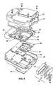
- the location of the battery assembly in front of the PCMCIA memory card slotprevents the defibrillator operator or others from accessing the PCMCIA card while the defibrillator is powered up and operating. This arrangement protects the operator and patient from accidental shocks and protects the defibrillator itself from damage caused by inadvertant removal of the PCMCIA card during operation.
Landscapes
- Health & Medical Sciences (AREA)
- Cardiology (AREA)
- Heart & Thoracic Surgery (AREA)
- Engineering & Computer Science (AREA)
- Biomedical Technology (AREA)
- Nuclear Medicine, Radiotherapy & Molecular Imaging (AREA)
- Radiology & Medical Imaging (AREA)
- Life Sciences & Earth Sciences (AREA)
- Animal Behavior & Ethology (AREA)
- General Health & Medical Sciences (AREA)
- Public Health (AREA)
- Veterinary Medicine (AREA)
- Electrotherapy Devices (AREA)
- Finger-Pressure Massage (AREA)
Abstract
Description
The system impedance is measured during delivery of that shock and the measuredimpedance is used to alter the shape of asubsequently delivered shock.
The preferred defibrillator apparatus weighs less than 4 pounds (1.8kg) and has avolume less than 150 cubic inches (2.51) and most preferably, weighs approximatelythree pounds (1.4kg) or less and has a volume of approximately 141 cu.in (2.31).
Peak current values above the threshold could indicate ashort circuit condition.
| If t(Ot) < (mS) | Then t (Φ1) is (mS) |
| 1.13 | 2.3 |
| 1.60 | 2.85 |
| 2.07 | 3.79 |
| 2.56 | 4.02 |
| 3.07 | 4.83 |
| 3.58 | 6.76 |
| 4.10 | 7.73 |
| 4.64 | 8.69 |
| 5.20 | 9.66 |
| 5.77 | 10.62 |
| 6.35 | 11.59 |
| If t(Vt) < (mS) | Then t(Φ1) is (mS) |
| 1.24 | 2.3 |
| 1.73 | 2.85 |
| 2.23 | 3.79 |
| 2.72 | 4.02 |
| 3.22 | 4.83 |
| 3.71 | 6.76 |
| 4.20 | 7.73 |
| 4.70 | 8.69 |
| 5.19 | 9.66 |
| 5.69 | 10.62 |
| 6.18 | 11.59 |
Claims (21)
- An apparatus for administering electrotherapy to a patient's heartthrough electrodes external to the patient, comprising:characterised by further comprising a controller (38) arranged to operate theconnecting mechanism to deliver electrical energy from the energy source (32) to theelectrodes (36) in a truncated exponential multiphasic waveform, the relationshipbetween the phase durations of which waveform is based on an electrical parametermonitored during delivery of the electrical energy.an energy source (32);two electrodes (36) adapted to make electrical contact with a patient; anda connecting mechanism (34) for forming an electrical circuit with the energysource (32) and the electrodes (36) when the electrodes (36) are attached to thepatient, and
- The apparatus of claim 1, wherein the connecting mechanism (34)comprises a plurality of switches (56, 58, 60, 62) for selectively directing electricalenergy from the energy source to the patient in one of two polarities.
- The apparatus of claim 1 or claim 2, further comprising a chargesensor (70) providing information to the controller related to charge delivered by theenergy source (32) to the electrodes (36).
- The apparatus of claim 3, further comprising a timer (40) associatedwith the charge sensor (70) and the controller (38).
- The apparatus of any one of the preceding claims, wherein thecontroller (38) comprises a counter with a controllable counting rate, the counterbeing adapted to count in one direction during delivery of a first phase of themultiphasic waveform and in another direction during delivery of a second phase of the multiphasic waveform.
- The apparatus of any one of the preceding claims, further comprisingmeans (64, 66) for selectively limiting current flow through the electrodes and means(68) for determining whether current flowing to the electrodes (36) is below apredetermined threshold.
- The apparatus of claim 6, wherein the means for selectively limitingcurrent flow comprises an impedance (64) and a shunting switch (66) in the circuitwith the electrodes (36) and the energy source (32).
- The apparatus of any one of the preceding claims, wherein the energysource (32) comprises at least one battery (94) disposed in a battery holder (92), theapparatus further comprising a solid state memory device (83) disposed in a memorydevice holder (95), the battery (94) blocking external access to the memory device(83) when the battery (94) is disposed in the battery holder (92).
- The apparatus of claim 8, wherein the energy source comprisesprimary cell batteries (94).
- The apparatus of claim 9, wherein the primary cell batteries arelithium manganese dioxide primary batteries (94).
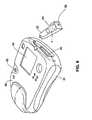
- The apparatus of any one of the preceding claims, further comprisinga housing (80, 81) containing at least the energy source (32), the connectingmechanism (34) and the controller (38), the housing (80, 81) having a volume lessthan 150 cubic inches (2.51).
- The apparatus of claim 11, wherein the housing has a first dimensionnot greater than 2.2 inches (5.6 cm).
- The apparatus of claim 12, wherein the housing has second and thirddimensions not greater than 8 inches (20 cm).
- The apparatus of any one of the preceding claims, wherein theapparatus has a weight less than four pounds (1.8 kg).
- The apparatus of any one of the preceding claims, wherein theconnecting mechanism (34) and the controller (38) are arranged to deliver amultiphasic waveform without the use of an inductor.
- The apparatus of any one of the preceding claims, wherein the energysource comprises a capacitor (32) and the apparatus further comprises a capacitorprecharge circuit.
- The apparatus of any one of the preceding claims, wherein the energysource is a capacitive energy source sized between 60 and 150 microfarads.
- The apparatus of any one of the preceding claims, further comprisingan ECG system (50).
- The apparatus of claim 18, further comprising an LCD display (88).
- The apparatus of any one of the preceding claims, further comprisinga PCMCLA memory card (83).
- The apparatus of claim 20 when appendent to claim 19, further comprising means for displaying ECG information stored in the PCMCIA memory(83) on the LCD display (88).
Priority Applications (1)
| Application Number | Priority Date | Filing Date | Title |
|---|---|---|---|
| EP00102328AEP0997162B2 (en) | 1993-08-06 | 1994-07-19 | Electrotherapy apparatus |
Applications Claiming Priority (5)
| Application Number | Priority Date | Filing Date | Title |
|---|---|---|---|
| US10383793A | 1993-08-06 | 1993-08-06 | |
| US103837 | 1993-08-06 | ||
| US227553 | 1994-04-14 | ||
| US08/227,553US5607454A (en) | 1993-08-06 | 1994-04-14 | Electrotherapy method and apparatus |
| PCT/US1994/008134WO1995005215A2 (en) | 1993-08-06 | 1994-07-19 | Electrotherapy method and apparatus |
Related Child Applications (2)
| Application Number | Title | Priority Date | Filing Date |
|---|---|---|---|
| EP00102328ADivisionEP0997162B2 (en) | 1993-08-06 | 1994-07-19 | Electrotherapy apparatus |
| EP00102328.2Division-Into | 2000-02-03 |
Publications (3)
| Publication Number | Publication Date |
|---|---|
| EP0712321A1 EP0712321A1 (en) | 1996-05-22 |
| EP0712321A4 EP0712321A4 (en) | 1997-12-17 |
| EP0712321B1true EP0712321B1 (en) | 2004-04-07 |
Family
ID=26800907
Family Applications (2)
| Application Number | Title | Priority Date | Filing Date |
|---|---|---|---|
| EP94922627AExpired - LifetimeEP0712321B1 (en) | 1993-08-06 | 1994-07-19 | Electrotherapy apparatus |
| EP00102328AExpired - LifetimeEP0997162B2 (en) | 1993-08-06 | 1994-07-19 | Electrotherapy apparatus |
Family Applications After (1)
| Application Number | Title | Priority Date | Filing Date |
|---|---|---|---|
| EP00102328AExpired - LifetimeEP0997162B2 (en) | 1993-08-06 | 1994-07-19 | Electrotherapy apparatus |
Country Status (10)
| Country | Link |
|---|---|
| US (3) | US5607454A (en) |
| EP (2) | EP0712321B1 (en) |
| JP (4) | JPH09500309A (en) |
| AT (1) | ATE263598T1 (en) |
| AU (1) | AU7367294A (en) |
| CA (1) | CA2168978A1 (en) |
| DE (2) | DE69433686T2 (en) |
| ES (1) | ES2215998T3 (en) |
| NO (1) | NO960470L (en) |
| WO (1) | WO1995005215A2 (en) |
Families Citing this family (251)
| Publication number | Priority date | Publication date | Assignee | Title |
|---|---|---|---|---|
| US5601612A (en)* | 1993-08-06 | 1997-02-11 | Heartstream, Inc. | Method for applying a multiphasic waveform |
| US5540723A (en) | 1993-10-06 | 1996-07-30 | Duke University | Method and apparatus for delivering an optimum shock duration in treating cardiac arrhythmias |
| US6853859B1 (en)* | 1994-05-31 | 2005-02-08 | Galvani, Ltd. | Electrical cardiac output forcer |
| US6185457B1 (en)* | 1994-05-31 | 2001-02-06 | Galvani, Ltd. | Method and apparatus for electrically forcing cardiac output in an arrhythmia patient |
| US5691881A (en)* | 1995-05-16 | 1997-11-25 | Hewlett-Packard Company | Electronic device having E-PAC chassis for spatial arrangement of components and cable organization including channel with retaining wall preventing cable from dislodging from an edge connector |
| US5620465A (en)* | 1995-06-08 | 1997-04-15 | Survivalink Corporation | External defibrillator for producing and testing biphasic waveforms |
| US5797969A (en)* | 1995-08-01 | 1998-08-25 | Survivalink Corporation | One button lid activated automatic external defibrillator |
| US5645571B1 (en)* | 1995-08-01 | 1999-08-24 | Surviva Link Corp | Automated external defibrillator with lid activated self-test system |
| US5967817A (en) | 1995-11-21 | 1999-10-19 | Heartstream, Inc. | Medical connector apparatus |
| WO1997031680A1 (en)* | 1996-03-01 | 1997-09-04 | Heartstream, Inc. | Electrotherapy method and apparatus |
| EP0892656A4 (en) | 1996-04-12 | 2000-08-30 | Survivalink Corp | External defibrillator having low capacitance and small time constant |
| US5899924A (en) | 1996-04-12 | 1999-05-04 | Survivalink Corporation | Single capacitor truncated damped sinusoidal defibrillation waveform |
| US5741306A (en)* | 1996-05-23 | 1998-04-21 | Lifecor, Inc. | Patient-worn energy delivery apparatus |
| US5909138A (en)* | 1996-06-27 | 1999-06-01 | Survivalink Corporation | Fast isolated IGBT driver for high voltage switching circuitry |
| US5836972A (en)* | 1996-06-27 | 1998-11-17 | Survivalink Corp. | Parallel charging of mixed capacitors |
| US5891172A (en)* | 1996-06-27 | 1999-04-06 | Survivalink Corporation | High voltage phase selector switch for external defibrillators |
| US5991658A (en)* | 1996-07-01 | 1999-11-23 | Survivalink Corporation | Continual waveform shape reforming method and apparatus for transchest resistance dynamics |
| US6411846B1 (en) | 1999-08-26 | 2002-06-25 | Survivalink Corporation | Method and apparatus for delivering a biphasic defibrillation pulse with variable energy |
| US5968080A (en)* | 1996-07-01 | 1999-10-19 | Survivalink Corporation | Method for determining the second phase of external defibrillator devices |
| US6263239B1 (en) | 1996-07-01 | 2001-07-17 | Survivalink Corporation | Method and apparatus for determining the second phase of defibrillator devices |
| US5893049A (en)* | 1996-08-06 | 1999-04-06 | Pacesetter, Inc. | Rapid response voltage threshold determination circuit for electrophysiology diagnostic device |
| JP4108758B2 (en) | 1996-12-18 | 2008-06-25 | ズィーエムディー コーポレーション | Current waveform of electrotherapy |
| US5797968A (en)* | 1996-12-18 | 1998-08-25 | Zmd Corporation | Electrotherapy circuit for producing current waveform with sawtooth ripple |
| US6096063A (en)* | 1996-12-18 | 2000-08-01 | Zmd Corporation | Electrotherapy circuit having controlled current discharge based on patient-dependent electrical parameter |
| US5800462A (en)* | 1996-12-18 | 1998-09-01 | Zmd Corporation | Electrotherapy circuit for producing therapeutic discharge waveform based on high-current sensing pulse |
| US5769872A (en)* | 1996-12-18 | 1998-06-23 | Zmd Corporation | Electrotherapy circuit and method for shaping current waveforms |
| US5904706A (en)* | 1996-12-18 | 1999-05-18 | Zmd Corporation | Method and apparatus for producing electrotherapy current waveform with ripple |
| US5800463A (en)* | 1996-12-18 | 1998-09-01 | Zmd Corporation | Electrotherapy circuit having controlled peak current |
| US5733310A (en)* | 1996-12-18 | 1998-03-31 | Zmd Corporation | Electrotherapy circuit and method for producing therapeutic discharge waveform immediately following sensing pulse |
| US6175765B1 (en) | 1997-03-05 | 2001-01-16 | Medtronic Physio-Control Manufacturing Corp. | H-bridge circuit for generating a high-energy biphasic waveform in an external defibrillator |
| US6963773B2 (en)* | 1997-03-05 | 2005-11-08 | Medtronic Physio-Control Manufacturing Corp. | H-bridge circuit for generating a high-energy biphasic waveform in an external defibrillator using single SCR and IGBT switches in an integrated package |
| US5824017A (en)* | 1997-03-05 | 1998-10-20 | Physio-Control Corporation | H-bridge circuit for generating a high-energy biphasic waveform in an external defibrillator |
| US5873893A (en)* | 1997-03-05 | 1999-02-23 | Physio-Control Corporation | Method and apparatus for verifying the integrity of an output circuit before and during application of a defibrillation pulse |
| US6148233A (en)* | 1997-03-07 | 2000-11-14 | Cardiac Science, Inc. | Defibrillation system having segmented electrodes |
| WO1998044990A1 (en)* | 1997-04-08 | 1998-10-15 | Survivlink Corporation | Aami specification optimized truncated exponential waveform |
| US6088616A (en)* | 1997-04-10 | 2000-07-11 | Survivalink Corporation | Field programmable automated external defibrillator |
| IL131821A (en)* | 1997-04-18 | 2004-07-25 | Physio Control Mfg Corp | Heart defibrillator apparatus and method |
| US5899925A (en)* | 1997-08-07 | 1999-05-04 | Heartstream, Inc. | Method and apparatus for aperiodic self-testing of a defibrillator |
| US5931791A (en)* | 1997-11-05 | 1999-08-03 | Instromedix, Inc. | Medical patient vital signs-monitoring apparatus |
| DE69829358T2 (en) | 1997-11-06 | 2006-04-06 | Koninklijke Philips Electronics N.V. | EXTERNAL DEFIBRILLATOR WITH CPR INDICATIONS AND WITH ACLS INDICATIONS |
| US5974339A (en)* | 1997-11-26 | 1999-10-26 | Procath Corporation | High energy defibrillator employing current control circuitry |
| USD414870S (en) | 1998-01-02 | 1999-10-05 | Instromedix, Inc. | Vital signs monitor |
| US6083246A (en)* | 1998-04-08 | 2000-07-04 | Survivalink Corporation | Lid open detection circuit for automated external defibrillators |
| US6539255B1 (en) | 1998-07-16 | 2003-03-25 | Cardiac Science, Inc. | Full-tilt exponential defibrillation waveform |
| US6693431B1 (en) | 1998-08-28 | 2004-02-17 | Koninklijke Philips Electronics N.V. | Battery system and method of determining battery condition |
| US6108578A (en) | 1998-09-02 | 2000-08-22 | Heartstream, Inc. | Configurable arrhythmia analysis algorithm |
| US6173204B1 (en) | 1998-10-13 | 2001-01-09 | Physio-Control Manufacturing Corporation | Semiconductor assisted relay in a biphasic defibrillator |
| US6212429B1 (en) | 1998-10-13 | 2001-04-03 | Physio-Control Manufacturing Corporation | Method and apparatus for converting a monophasic defibrillator to a biphasic defibrillator |
| US6208895B1 (en)* | 1998-10-13 | 2001-03-27 | Physio-Control Manufacturing Corporation | Circuit for performing external pacing and biphasic defibrillation |
| US6208896B1 (en) | 1998-11-13 | 2001-03-27 | Agilent Technologies, Inc. | Method and apparatus for providing variable defibrillation waveforms using switch-mode amplification |
| US6887244B1 (en)* | 1998-12-16 | 2005-05-03 | Medtronic, Inc. | Cordless surgical handpiece with disposable battery; and method |
| FR2788699B1 (en) | 1999-01-27 | 2001-05-25 | Bruker Medical Sa | PULSES OR SERIES OF DEFIBRILLATION PULSES AND DEVICE FOR GENERATING THE SAME |
| AU2568200A (en)* | 1999-02-08 | 2000-08-29 | James Allen | Apparatus for determining when a patient is susceptible to defibrillation |
| US6208898B1 (en)* | 1999-03-25 | 2001-03-27 | Agilent Technologies, Inc. | Impedance estimation with dynamic waveform control in an electrotherapy apparatus |
| US6234816B1 (en) | 1999-03-30 | 2001-05-22 | Agilant Technologies, Inc. | Medical connector apparatus |
| US6266561B1 (en) | 1999-04-01 | 2001-07-24 | Agilent Technologies, Inc. | Method of adjusting electrotherapy in response to an arrhythmia |
| US6241751B1 (en) | 1999-04-22 | 2001-06-05 | Agilent Technologies, Inc. | Defibrillator with impedance-compensated energy delivery |
| US6266562B1 (en) | 1999-04-30 | 2001-07-24 | Agilent Technologies, Inc. | Defibrillator with automated test load |
| US6317635B1 (en) | 1999-06-30 | 2001-11-13 | Dennis E. Ochs | Sensor responsive electrotherapy apparatus |
| US20020193844A1 (en)* | 1999-07-08 | 2002-12-19 | Michelson Steve A. | Combination electrode-battery assembly for a miniature wireless transcutaneous electrical neuro or muscular-stimulation unit |
| US6445955B1 (en) | 1999-07-08 | 2002-09-03 | Stephen A. Michelson | Miniature wireless transcutaneous electrical neuro or muscular-stimulation unit |
| US20020019652A1 (en) | 1999-07-08 | 2002-02-14 | Cyclotec Advanced Medical Technologies | Two part tens bandage |
| US6298266B1 (en)* | 1999-08-10 | 2001-10-02 | Intermedics Inc. | Methods and apparatus for treating fibrillation and creating defibrillation waveforms |
| US6738664B1 (en) | 1999-09-24 | 2004-05-18 | The Curators Of The University Of Missouri | Method of and apparatus for atrial and ventricular defibrillation or cardioversion with an electrical waveform optimized in the frequency domain |
| US6353758B1 (en) | 1999-09-29 | 2002-03-05 | Bradford E Gliner | Apparatus and method for delivering a low energy therapeutic pulse to a patient |
| US6438415B1 (en) | 1999-10-01 | 2002-08-20 | Daniel J Powers | Method and apparatus for controlling the operation and functionality of an electrotherapy device |
| US6314320B1 (en)* | 1999-10-01 | 2001-11-06 | Daniel J Powers | Method and apparatus for selectively inactivating AED functionality |
| US6546287B1 (en) | 1999-10-08 | 2003-04-08 | Purdue Research Foundation | Controlled-power defibrillator and method of defibrillation |
| US6360120B1 (en) | 1999-10-13 | 2002-03-19 | Daniel J Powers | Method and apparatus for transferring patient data generated by an external defibrillator |
| US6304783B1 (en) | 1999-10-14 | 2001-10-16 | Heartstream, Inc. | Defibrillator system including a removable monitoring electrodes adapter and method of detecting the monitoring adapter |
| US6990371B2 (en) | 1999-10-14 | 2006-01-24 | Koninklijke Philips Electronics N.V. | Method and apparatus for providing on-screen incident review in an AED |
| DE10064965B4 (en)* | 1999-12-29 | 2007-01-04 | Metrax Gmbh | Medical device for applying electrical energy to a patient |
| US6647290B2 (en) | 2000-01-18 | 2003-11-11 | Koninklijke Philips Electronics N.V. | Charge-based defibrillation method and apparatus |
| WO2001060454A1 (en)* | 2000-02-18 | 2001-08-23 | Heartsine Technologies, Inc. | A defibrillator |
| US6421563B1 (en)* | 2000-03-01 | 2002-07-16 | Medtronic Physio-Control Manufacturing Corp. | Solid-state multiphasic defibrillation circuit |
| JP4221687B2 (en) | 2000-03-08 | 2009-02-12 | 日本光電工業株式会社 | ELECTROTHERAPY DEVICE AND ITS ELECTRIC ENERGY OUTPUT METHOD |
| US6441582B1 (en) | 2000-03-29 | 2002-08-27 | Koninklijke Phillips Electronics N.V. | Battery arrangement for improved defibrillator safety |
| US7016726B1 (en) | 2000-05-17 | 2006-03-21 | Koninklijke Philips Electronics N.V. | Smart medical connector system and method of use |
| US7463922B1 (en) | 2000-07-13 | 2008-12-09 | Koninklijke Philips Electronics, N.V. | Circuit and method for analyzing a patient's heart function using overlapping analysis windows |
| US6778860B2 (en)* | 2001-11-05 | 2004-08-17 | Cameron Health, Inc. | Switched capacitor defibrillation circuit |
| US6721597B1 (en) | 2000-09-18 | 2004-04-13 | Cameron Health, Inc. | Subcutaneous only implantable cardioverter defibrillator and optional pacer |
| US6754528B2 (en) | 2001-11-21 | 2004-06-22 | Cameraon Health, Inc. | Apparatus and method of arrhythmia detection in a subcutaneous implantable cardioverter/defibrillator |
| US6539258B1 (en) | 2000-10-06 | 2003-03-25 | Medtronic Physio-Control Manufacturing Corp. | Energy adjusting circuit for producing an ultra-low energy defibrillation waveform with fixed pulse width and fixed tilt |
| US6556864B1 (en) | 2000-11-13 | 2003-04-29 | Koninklijke Philips Electronics N.V. | Object activated defibrillator |
| US6675051B2 (en) | 2000-12-22 | 2004-01-06 | Koninklijke Philips Electronics N.V. | See-through electrode-pad package and method for using a storage system that includes the package |
| US6662056B2 (en) | 2000-12-22 | 2003-12-09 | Koninklijke Philips Electronics N.V. | Cartridge for storing an electrode pad |
| US6493581B2 (en) | 2000-12-28 | 2002-12-10 | Koninklijke Philips Electronics N.V. | System and method for rapid recruitment of widely distributed easily operated automatic external defibrillators |
| US6871093B2 (en) | 2000-12-28 | 2005-03-22 | Koninklijke Philips Electronics N.V. | Reporting the status for an external defibrillator with an audible report in response to a specified user input |
| US6668193B2 (en) | 2001-01-04 | 2003-12-23 | Cardiac Pacemakers, Inc. | Method and apparatus for cardiac shock therapy |
| US6546286B2 (en) | 2001-02-27 | 2003-04-08 | Koninklijke Philips Electronics N.V. | Battery-less, human-powered electrotherapy device |
| US6935889B2 (en)* | 2001-02-28 | 2005-08-30 | Koninklijke Philips Electronics N.V. | Electrode-pad package that is removable from an electrode-pad lead and method for opening the package |
| US6553257B2 (en) | 2001-03-13 | 2003-04-22 | Koninklijke Philips Electronics N.V. | Interactive method of performing cardipulmonary resuscitation with minimal delay to defibrillation shocks |
| US6560485B2 (en) | 2001-03-27 | 2003-05-06 | Koninklijke Philips Electronics N.V. | Four contact identification defibrillator electrode system |
| US6650936B2 (en) | 2001-04-23 | 2003-11-18 | Medtronic Physio-Control Manufacturing Corporation. | Method and apparatus for delivering electrotherapy having an equivalent probability of success for different patients |
| US6671547B2 (en) | 2001-06-13 | 2003-12-30 | Koninklijke Philips Electronics N.V. | Adaptive analysis method for an electrotherapy device and apparatus |
| US6625487B2 (en) | 2001-07-17 | 2003-09-23 | Koninklijke Philips Electronics N.V. | Bioelectrical impedance ECG measurement and defibrillator implementing same |
| US6567698B2 (en) | 2001-07-17 | 2003-05-20 | Koninklijke Philips Electronics N.V. | System and method for applying sequential low energy defibrillation pulses |
| US20030028219A1 (en) | 2001-07-20 | 2003-02-06 | Powers Daniel J. | Modular medical device, base unit and module thereof, and automated external defibrillator (AED), methods for assembling and using the AED |
| US7848805B2 (en)* | 2001-07-20 | 2010-12-07 | Koninklijke Philips Electronics N.V. | Modular medical device, base unit and module thereof, and automated external defibrillator (AED), methods for assembling and using the AED |
| US20030125771A1 (en)* | 2001-08-01 | 2003-07-03 | Medical Research Laboratories, Inc. | Multiphasic defibrillator utilizing controlled energy pulses |
| USD452012S1 (en) | 2001-08-14 | 2001-12-11 | Barney L. Phillips | Medical monitoring device |
| WO2003020362A2 (en)* | 2001-08-31 | 2003-03-13 | Access Cardiosystems, Inc. | Automated external defibrillator (aed) system |
| US7016727B2 (en) | 2001-11-05 | 2006-03-21 | Koninklijke Philips Electronics N.V. | Cartridge having a power source and electrode pad for defibrillator having a rechargeable battery |
| US6813517B2 (en) | 2001-11-06 | 2004-11-02 | Medtronic Physio-Control Corp. | Configuring defibrillator energy dosing |
| US7151963B2 (en)* | 2001-12-03 | 2006-12-19 | Medtronic, Inc. | Control of arbitrary waveforms for constant delivered energy |
| US6662046B2 (en) | 2001-12-21 | 2003-12-09 | Koninklijke Philips Electronics N.V. | Defibrillator with automatic turn on, defibrillator storage case, and related system and method |
| US6965796B2 (en)* | 2002-03-11 | 2005-11-15 | Medtronic Physio-Control Manufacturing Corp. | Method and apparatus for self-test of defibrillation and pacing circuits including a patient isolation switch |
| US7096062B2 (en)* | 2002-03-11 | 2006-08-22 | Medtronic Physio-Control Manufacturing Corp. | Method for self-test of defibrillation and pacing circuits including a patient isolation switch |
| US6980859B2 (en) | 2002-03-22 | 2005-12-27 | Koninklijke Philips Electronics N.V. | Automated external defibrillator with a plurality of power sources |
| US8417327B2 (en)* | 2002-06-20 | 2013-04-09 | Physio-Control, Inc. | Variable frequency impedance measurement |
| US6968230B2 (en) | 2002-06-26 | 2005-11-22 | Medtronic Physio-Control Manufacturing Corp | H-bridge circuit for generating a high-energy biphasic and external pacing waveform in an external defibrillator |
| EP1382369A1 (en)* | 2002-07-20 | 2004-01-21 | Schiller AG | Device for electrotherapy and method of testing and operating the same |
| US20040044371A1 (en)* | 2002-09-04 | 2004-03-04 | Medtronic Physio-Control Manufacturing Corp. | Defibrillator with H-bridge output circuit referenced to common ground |
| US6873133B1 (en)* | 2002-09-11 | 2005-03-29 | Medtronic Physio-Control Manufacturing Corporation | Defibrillator with a reconfigurable battery module |
| US7920917B2 (en)* | 2003-07-17 | 2011-04-05 | Physio-Control, Inc. | External defibrillator and methods for operating the external defibrillator |
| US7242979B1 (en) | 2002-09-20 | 2007-07-10 | Medtronic Physio-Control Manufacturing Corporation | External defibrillator and methods for operating the external defibrillator |
| US20040064154A1 (en)* | 2002-09-30 | 2004-04-01 | Norton John D. | Apparatus and method for optimizing capacitor charge in a medical device |
| US20040088011A1 (en)* | 2002-10-31 | 2004-05-06 | Koninklijke Philips Electronics N.V. | Defibrillation circuit that can compensate for a variation in a patient parameter and related defibrillator and method |
| US7272441B1 (en) | 2002-11-13 | 2007-09-18 | Medtronic Physio-Control Manufacturing Corp. | External defibrillator and methods for operating the external defibrillator |
| US7174208B2 (en)* | 2002-12-03 | 2007-02-06 | Medtronic, Inc. | Slow rise defibrillation waveforms to minimize stored energy for a pulse modulated circuit and maximize charge transfer to myocardial membrane |
| US7617007B2 (en)* | 2003-06-04 | 2009-11-10 | Synecor Llc | Method and apparatus for retaining medical implants within body vessels |
| US7082336B2 (en) | 2003-06-04 | 2006-07-25 | Synecor, Llc | Implantable intravascular device for defibrillation and/or pacing |
| US8239045B2 (en)* | 2003-06-04 | 2012-08-07 | Synecor Llc | Device and method for retaining a medical device within a vessel |
| CA2527909A1 (en) | 2003-06-04 | 2005-01-06 | Synecor Llc | Intravascular electrophysiological system and methods |
| US20050049654A1 (en)* | 2003-08-28 | 2005-03-03 | Peter Lathrop | Ultralight pre-programmed microprocessor based electrotherapy technology |
| US20050065558A1 (en)* | 2003-09-19 | 2005-03-24 | Powers Daniel J. | External defibrillator having a removable battery pack using off-the-shelf cells |
| US20050070983A1 (en)* | 2003-09-25 | 2005-03-31 | Rugnetta Jaime L. | Lead system having lead body with minimized cross-section |
| EP1673144B1 (en)* | 2003-09-30 | 2008-10-15 | Koninklijke Philips Electronics N.V. | Identification system for defibrillator electrode package |
| USD499183S1 (en) | 2003-10-01 | 2004-11-30 | Defibtech, Llc | Enclosure for an automatic external defibrillator |
| US8014859B2 (en)* | 2003-10-02 | 2011-09-06 | Defibtech, Llc | External defibrillator enclosure with accessory storage slot |
| WO2005034154A2 (en)* | 2003-10-06 | 2005-04-14 | Koninklijke Philips Electronics, N.V. | Apparatus and method for packaging a capacitor |
| EP1701766A2 (en)* | 2003-12-12 | 2006-09-20 | Synecor, LLC | Implantable medical device having pre-implant exoskeleton |
| AU2005212341B2 (en)* | 2004-02-10 | 2011-11-24 | Synecor, Llc. | Intravascular delivery system for therapeutic agents |
| KR20060134064A (en)* | 2004-02-19 | 2006-12-27 | 코닌클리케 필립스 일렉트로닉스 엔.브이. | Method and apparatus for broadcasting audible information induced from extracorporeal ventricular defibrillators |
| US7346382B2 (en) | 2004-07-07 | 2008-03-18 | The Cleveland Clinic Foundation | Brain stimulation models, systems, devices, and methods |
| US7224575B2 (en) | 2004-07-16 | 2007-05-29 | Cardiac Pacemakers, Inc. | Method and apparatus for high voltage aluminum capacitor design |
| US20060111750A1 (en)* | 2004-11-24 | 2006-05-25 | Bowers Kyle R | Automated external defibrillator (AED) with discrete sensing pulse for use in configuring a therapeutic biphasic waveform |
| US8401637B2 (en)* | 2004-11-24 | 2013-03-19 | Galvani, Ltd. | Medium voltage therapy applications in treating cardiac arrest |
| US7904152B2 (en)* | 2004-12-09 | 2011-03-08 | Physio-Control, Inc. | External defibrillator with charge advisory algorithm |
| CN101084040B (en) | 2004-12-20 | 2012-12-05 | 皇家飞利浦电子股份有限公司 | Automatic external defibrillator for adult and pediatric patients |
| FR2879937B1 (en)* | 2004-12-23 | 2008-01-11 | Schiller Medical Sas | DEFIBRILLATOR WHERE THE DISCHARGE CIRCUIT IS SECURED AND HAS AN H-BRIDGE |
| CN101098730A (en) | 2005-01-05 | 2008-01-02 | 皇家飞利浦电子股份有限公司 | Defibrillator event data with time correlation |
| JP5047942B2 (en)* | 2005-03-29 | 2012-10-10 | コーニンクレッカ フィリップス エレクトロニクス エヌ ヴィ | Impedance compensated defibrillator with energy supply function |
| US9339650B2 (en) | 2005-04-13 | 2016-05-17 | The Cleveland Clinic Foundation | Systems and methods for neuromodulation using pre-recorded waveforms |
| US8112154B2 (en)* | 2005-04-13 | 2012-02-07 | The Cleveland Clinic Foundation | Systems and methods for neuromodulation using pre-recorded waveforms |
| CN105013085A (en)* | 2005-08-04 | 2015-11-04 | 赛昂国际医疗控股有限公司 | automatic external defibrillator (AED) with wireless communication |
| US7457662B2 (en)* | 2005-09-09 | 2008-11-25 | Cardiac Science Corporation | Method and apparatus for variable capacitance defibrillation |
| US7821766B2 (en)* | 2007-04-19 | 2010-10-26 | Taser International, Inc. | Systems and methods for pulse delivery |
| US8150511B2 (en)* | 2006-06-29 | 2012-04-03 | Pacesetter, Inc. | Systems and methods for determining an optimal defibrillation shock waveform |
| US8024037B2 (en)* | 2006-08-01 | 2011-09-20 | Kumar Uday N | External defibrillator |
| US8170662B2 (en)* | 2006-08-03 | 2012-05-01 | Cardiac Pacemakers, Inc. | Method and apparatus for charging partitioned capacitors |
| US8761875B2 (en)* | 2006-08-03 | 2014-06-24 | Cardiac Pacemakers, Inc. | Method and apparatus for selectable energy storage partitioned capacitor |
| US8154853B2 (en)* | 2006-08-03 | 2012-04-10 | Cardiac Pacemakers, Inc. | Method and apparatus for partitioned capacitor |
| US20100131024A1 (en)* | 2006-10-06 | 2010-05-27 | Peter Lathrop | Electrotherapy orthopedic device |
| US8369944B2 (en) | 2007-06-06 | 2013-02-05 | Zoll Medical Corporation | Wearable defibrillator with audio input/output |
| US7962212B2 (en)* | 2007-08-02 | 2011-06-14 | Cameron Health, Inc. | Multiple battery configurations in an implantable medical device |
| WO2009036316A1 (en) | 2007-09-14 | 2009-03-19 | Corventis, Inc. | Energy management, tracking and security for adherent patient monitor |
| US8116841B2 (en) | 2007-09-14 | 2012-02-14 | Corventis, Inc. | Adherent device with multiple physiological sensors |
| US9186089B2 (en) | 2007-09-14 | 2015-11-17 | Medtronic Monitoring, Inc. | Injectable physiological monitoring system |
| WO2009036327A1 (en) | 2007-09-14 | 2009-03-19 | Corventis, Inc. | Adherent device for respiratory monitoring and sleep disordered breathing |
| EP3922171A1 (en) | 2007-09-14 | 2021-12-15 | Medtronic Monitoring, Inc. | Adherent cardiac monitor with advanced sensing capabilities |
| WO2009036369A1 (en) | 2007-09-14 | 2009-03-19 | Corventis, Inc. | System and methods for wireless body fluid monitoring |
| EP2194858B1 (en) | 2007-09-14 | 2017-11-22 | Corventis, Inc. | Medical device automatic start-up upon contact to patient tissue |
| JP5205389B2 (en)* | 2007-10-11 | 2013-06-05 | パナソニック株式会社 | High voltage generation circuit, puncture device and blood test device |
| US8260425B2 (en) | 2007-10-12 | 2012-09-04 | Intelect Medical, Inc. | Deep brain stimulation system with inputs |
| US8812123B2 (en)* | 2007-10-17 | 2014-08-19 | Intelect Medical, Inc. | Patient programmer with input and sensing capabilities |
| US9220889B2 (en) | 2008-02-11 | 2015-12-29 | Intelect Medical, Inc. | Directional electrode devices with locating features |
| US8019440B2 (en) | 2008-02-12 | 2011-09-13 | Intelect Medical, Inc. | Directional lead assembly |
| EP2257216B1 (en) | 2008-03-12 | 2021-04-28 | Medtronic Monitoring, Inc. | Heart failure decompensation prediction based on cardiac rhythm |
| WO2009146214A1 (en) | 2008-04-18 | 2009-12-03 | Corventis, Inc. | Method and apparatus to measure bioelectric impedance of patient tissue |
| US9272153B2 (en) | 2008-05-15 | 2016-03-01 | Boston Scientific Neuromodulation Corporation | VOA generation system and method using a fiber specific analysis |
| JP5559810B2 (en) | 2008-12-15 | 2014-07-23 | コーヴェンティス,インク. | Patient monitoring system and method |
| US20100268292A1 (en)* | 2009-04-16 | 2010-10-21 | Vishay Sprague, Inc. | Hermetically sealed wet electrolytic capacitor |
| US10028721B2 (en) | 2009-06-19 | 2018-07-24 | Koninklijke Philips N.V. | Biphasic defibrillator waveform with adjustable second phase tilt |
| US8483822B1 (en) | 2009-07-02 | 2013-07-09 | Galvani, Ltd. | Adaptive medium voltage therapy for cardiac arrhythmias |
| WO2011025865A1 (en) | 2009-08-27 | 2011-03-03 | The Cleveland Clinic Foundation | System and method to estimate region of tissue activation |
| WO2011050283A2 (en) | 2009-10-22 | 2011-04-28 | Corventis, Inc. | Remote detection and monitoring of functional chronotropic incompetence |
| WO2011068997A1 (en) | 2009-12-02 | 2011-06-09 | The Cleveland Clinic Foundation | Reversing cognitive-motor impairments in patients having a neuro-degenerative disease using a computational modeling approach to deep brain stimulation programming |
| US9451897B2 (en) | 2009-12-14 | 2016-09-27 | Medtronic Monitoring, Inc. | Body adherent patch with electronics for physiologic monitoring |
| US8965498B2 (en) | 2010-04-05 | 2015-02-24 | Corventis, Inc. | Method and apparatus for personalized physiologic parameters |
| US8913804B2 (en) | 2010-06-14 | 2014-12-16 | Boston Scientific Neuromodulation Corporation | Programming interface for spinal cord neuromodulation |
| WO2012135062A1 (en) | 2011-03-25 | 2012-10-04 | Zoll Medical Corporation | Selection of optimal channel for rate determination |
| WO2012135028A1 (en) | 2011-03-25 | 2012-10-04 | Zoll Medical Corporation | Method of detecting signal clipping in a wearable ambulatory medical device |
| JP2014518516A (en) | 2011-03-29 | 2014-07-31 | ボストン サイエンティフィック ニューロモデュレイション コーポレイション | System and method for atlas alignment |
| US9227074B2 (en) | 2012-08-28 | 2016-01-05 | Boston Scientific Neuromodulation Corporation | Parameter visualization, selection, and annotation interface |
| US9592389B2 (en) | 2011-05-27 | 2017-03-14 | Boston Scientific Neuromodulation Corporation | Visualization of relevant stimulation leadwire electrodes relative to selected stimulation information |
| WO2013020135A1 (en) | 2011-08-04 | 2013-02-07 | Galvani Ltd. | Multi-modal electrotherapy method and apparatus |
| EP2742450A2 (en) | 2011-08-09 | 2014-06-18 | Boston Scientific Neuromodulation Corporation | Systems and methods for stimulation-related volume analysis, creation, and sharing |
| WO2013069003A1 (en)* | 2011-11-11 | 2013-05-16 | National University Of Ireland, Galway | Muscle stimulation device |
| USD704848S1 (en)* | 2012-01-13 | 2014-05-13 | Modular Therapeutx, Llc | Portable TENS device |
| WO2013130421A1 (en) | 2012-02-29 | 2013-09-06 | The Cleveland Clinic Foundation | System and method for neuromodulation using composite patterns of stimulation or waveforms |
| US8942800B2 (en) | 2012-04-20 | 2015-01-27 | Cardiac Science Corporation | Corrective prompting system for appropriate chest compressions |
| US9126055B2 (en) | 2012-04-20 | 2015-09-08 | Cardiac Science Corporation | AED faster time to shock method and device |
| US20140002241A1 (en) | 2012-06-29 | 2014-01-02 | Zoll Medical Corporation | Response system with emergency response equipment locator |
| EP2879757B1 (en) | 2012-08-04 | 2019-06-26 | Boston Scientific Neuromodulation Corporation | Systems and methods for storing and transferring registration, atlas, and lead information between medical devices |
| US9827435B2 (en)* | 2012-09-28 | 2017-11-28 | Physio-Control, Inc. | Defibrillator with sync mode assisting selection of feature to lock-on |
| US9792412B2 (en) | 2012-11-01 | 2017-10-17 | Boston Scientific Neuromodulation Corporation | Systems and methods for VOA model generation and use |
| US8750990B1 (en) | 2012-12-12 | 2014-06-10 | Galvani, Ltd. | Coordinated medium voltage therapy for improving effectiveness of defibrillation therapy |
| US10500403B2 (en) | 2013-02-25 | 2019-12-10 | West Affum Holdings Corp. | WCD system validating detected cardiac arrhythmias thoroughly so as to not sound loudly due to some quickly self-terminating cardiac arrhythmias |
| US12097379B2 (en) | 2013-02-25 | 2024-09-24 | West Affum Holdings Dac | Wearable cardioverter defibrillator (WCD) system making shock/no shock determinations from multiple patient parameters |
| US10543377B2 (en) | 2013-02-25 | 2020-01-28 | West Affum Holdings Corp. | Wearable cardioverter defibrillator (WCD) system making shock/no shock determinations by aggregating aspects of patient parameters |
| US9757579B2 (en) | 2013-02-25 | 2017-09-12 | West Affum Holdings Corp. | Wearable cardioverter defibrillator (WCD) system informing patient that it is validating just-detected cardiac arrhythmia |
| US9089685B2 (en)* | 2013-02-25 | 2015-07-28 | West Affum Holdings Corp. | Wearable defibrillator with a multivector shock waveform |
| EP2978491A4 (en) | 2013-03-29 | 2016-12-21 | Galvani Ltd | Cardiac-safe electrotherapy method and apparatus |
| CN106456984B (en) | 2014-02-24 | 2019-07-09 | 元素科学公司 | External defibrillator |
| US9872650B2 (en)* | 2014-05-19 | 2018-01-23 | Anthrotronix, Inc. | Electrodermal interface system |
| US9959388B2 (en) | 2014-07-24 | 2018-05-01 | Boston Scientific Neuromodulation Corporation | Systems, devices, and methods for providing electrical stimulation therapy feedback |
| US10272247B2 (en) | 2014-07-30 | 2019-04-30 | Boston Scientific Neuromodulation Corporation | Systems and methods for stimulation-related volume analysis, creation, and sharing with integrated surgical planning and stimulation programming |
| US10265528B2 (en) | 2014-07-30 | 2019-04-23 | Boston Scientific Neuromodulation Corporation | Systems and methods for electrical stimulation-related patient population volume analysis and use |
| US9974959B2 (en) | 2014-10-07 | 2018-05-22 | Boston Scientific Neuromodulation Corporation | Systems, devices, and methods for electrical stimulation using feedback to adjust stimulation parameters |
| USD759249S1 (en) | 2014-10-30 | 2016-06-14 | The American National Red Cross | Electronic device |
| CN107249682B (en)* | 2015-02-20 | 2018-10-12 | 赛纳吉亚医疗公司 | Photovoltaic electrical stimulation device |
| US10835449B2 (en) | 2015-03-30 | 2020-11-17 | Zoll Medical Corporation | Modular components for medical devices |
| CN107530542B (en) | 2015-05-26 | 2020-10-13 | 波士顿科学神经调制公司 | System for analyzing electrical stimulation and selecting or manipulating activation volume |
| US10780283B2 (en) | 2015-05-26 | 2020-09-22 | Boston Scientific Neuromodulation Corporation | Systems and methods for analyzing electrical stimulation and selecting or manipulating volumes of activation |
| EP3280490B1 (en) | 2015-06-29 | 2021-09-01 | Boston Scientific Neuromodulation Corporation | Systems for selecting stimulation parameters based on stimulation target region, effects, or side effects |
| ES2940303T3 (en) | 2015-06-29 | 2023-05-05 | Boston Scient Neuromodulation Corp | Stimulation parameter selection systems by use of targets and direction |
| EP4183446A1 (en) | 2015-08-26 | 2023-05-24 | Element Science, Inc. | Wearable defibrillation devices |
| WO2017062378A1 (en) | 2015-10-09 | 2017-04-13 | Boston Scientific Neuromodulation Corporation | System and methods for clinical effects mapping for directional stimulations leads |
| US10176930B2 (en) | 2016-01-14 | 2019-01-08 | Vishay Sprague, Inc. | Low profile flat wet electrolytic tantalum capacitor |
| WO2017146660A1 (en)* | 2016-02-24 | 2017-08-31 | Koc Universitesi | A system for decreasing the internal organ blood flow to alleviate hypotension, hypoglisemia and myocardial infarction with segmental non-invasive stimulation of sympathetic innervation to specific internal organs and their arterial smooth muscles |
| US10716942B2 (en) | 2016-04-25 | 2020-07-21 | Boston Scientific Neuromodulation Corporation | System and methods for directional steering of electrical stimulation |
| EP3458152B1 (en) | 2016-06-24 | 2021-04-21 | Boston Scientific Neuromodulation Corporation | Systems and methods for visual analytics of clinical effects |
| WO2018044881A1 (en) | 2016-09-02 | 2018-03-08 | Boston Scientific Neuromodulation Corporation | Systems and methods for visualizing and directing stimulation of neural elements |
| US10780282B2 (en) | 2016-09-20 | 2020-09-22 | Boston Scientific Neuromodulation Corporation | Systems and methods for steering electrical stimulation of patient tissue and determining stimulation parameters |
| ES2869184T3 (en) | 2016-10-14 | 2021-10-25 | Boston Scient Neuromodulation Corp | Systems to determine in closed loop the configuration of the stimulation parameters of an electrical stimulation system |
| US10903675B2 (en) | 2016-12-12 | 2021-01-26 | Avive Solutions, Inc. | Medical device draw current regulation |
| US10449380B2 (en) | 2016-12-12 | 2019-10-22 | Revive Solutions, Inc. | Defibrillator |
| US11607555B2 (en) | 2016-12-12 | 2023-03-21 | Avive Solutions, Inc. | Defibrillator discharge control |
| JP7257681B2 (en) | 2016-12-12 | 2023-04-14 | アバイブ・ソリューションズ・インコーポレーテッド | defibrillator |
| JP6834005B2 (en) | 2017-01-03 | 2021-02-24 | ボストン サイエンティフィック ニューロモデュレイション コーポレイション | Systems and methods for selecting MRI-matched stimulus parameters |
| EP3519043B1 (en) | 2017-01-10 | 2020-08-12 | Boston Scientific Neuromodulation Corporation | Systems and methods for creating stimulation programs based on user-defined areas or volumes |
| US10625082B2 (en) | 2017-03-15 | 2020-04-21 | Boston Scientific Neuromodulation Corporation | Visualization of deep brain stimulation efficacy |
| US11357986B2 (en) | 2017-04-03 | 2022-06-14 | Boston Scientific Neuromodulation Corporation | Systems and methods for estimating a volume of activation using a compressed database of threshold values |
| US10946207B2 (en) | 2017-05-27 | 2021-03-16 | West Affum Holdings Corp. | Defibrillation waveforms for a wearable cardiac defibrillator |
| JP6932835B2 (en) | 2017-07-14 | 2021-09-08 | ボストン サイエンティフィック ニューロモデュレイション コーポレイション | Systems and methods for estimating the clinical effects of electrical stimulation |
| EP3634569A1 (en) | 2017-08-15 | 2020-04-15 | Boston Scientific Neuromodulation Corporation | Systems and methods for controlling electrical stimulation using multiple stimulation fields |
| US11471693B1 (en) | 2018-02-14 | 2022-10-18 | West Affum Holdings Dac | Wearable cardioverter defibrillator (WCD) system choosing to consider ECG signals from different channels per QRS complex widths of the ECG signals |
| US11865354B1 (en) | 2018-02-14 | 2024-01-09 | West Affum Holdings Dac | Methods and systems for distinguishing VT from VF |
| US12179032B2 (en) | 2018-02-14 | 2024-12-31 | West Affum Holdings Dac | Wearable cardioverter defibrillator (WCD) segment based episode opening and confirmation periods |
| US11160990B1 (en) | 2018-02-14 | 2021-11-02 | West Affum Holdings Corp. | Wearable cardioverter defibrillator (WCD) alarms |
| EP3784332B1 (en) | 2018-04-27 | 2023-04-26 | Boston Scientific Neuromodulation Corporation | Systems for visualizing and programming electrical stimulation |
| US11298553B2 (en) | 2018-04-27 | 2022-04-12 | Boston Scientific Neuromodulation Corporation | Multi-mode electrical stimulation systems and methods of making and using |
| US11942222B2 (en) | 2018-06-18 | 2024-03-26 | Zoll Medical Corporation | Medical device for estimating risk of patient deterioration |
| US11189431B2 (en) | 2018-07-16 | 2021-11-30 | Vishay Sprague, Inc. | Low profile wet electrolytic tantalum capacitor |
| CA3112450A1 (en) | 2018-10-10 | 2020-04-16 | Element Science, Inc. | Wearable medical device with disposable and reusable components |
| EP3771479B1 (en)* | 2019-08-02 | 2024-12-25 | BIOTRONIK SE & Co. KG | Treatment in the event of electrode error |
| EP4157439A1 (en)* | 2020-05-26 | 2023-04-05 | Zoll Medical Corporation | Electrotherapeutic waveform and pulse generation and delivery system and method |
| US12403315B2 (en) | 2021-04-27 | 2025-09-02 | Boston Scientific Neuromodulation Corporation | Systems and methods for automated programming of electrical stimulation |
| US12403313B2 (en) | 2021-06-15 | 2025-09-02 | Boston Scientific Neuromodulation Corporation | Methods and systems for estimating neural activation by stimulation using a stimulation system |
| US11742149B2 (en) | 2021-11-17 | 2023-08-29 | Vishay Israel Ltd. | Hermetically sealed high energy electrolytic capacitor and capacitor assemblies with improved shock and vibration performance |
Family Cites Families (59)
| Publication number | Priority date | Publication date | Assignee | Title |
|---|---|---|---|---|
| US3211154A (en)* | 1962-06-25 | 1965-10-12 | Mine Safety Appliances Co | Sequence switch for ventricular defibrillator |
| US3241555A (en)* | 1962-06-25 | 1966-03-22 | Mine Safety Appliances Co | Charging and discharging circuit for ventricular defibrillator |
| US3706313A (en)* | 1971-02-04 | 1972-12-19 | Medical Research Lab | Trapezoidal waveshape defibrillator |
| US3782239A (en)* | 1972-01-04 | 1974-01-01 | Us Army | Penetrating arrangement |
| US3862636A (en)* | 1972-01-20 | 1975-01-28 | Health Technology Labs Inc | Computer controlled defibrillator |
| US3782389A (en)* | 1972-01-20 | 1974-01-01 | Health Technology Labs Inc | Computer controlled defibrillator |
| US3886950A (en)* | 1973-10-01 | 1975-06-03 | Spacelabs Inc | Defibrillator |
| US3860009A (en)* | 1973-11-29 | 1975-01-14 | David Bell | Computer controlled defibrillator |
| GB1481469A (en)* | 1974-10-28 | 1977-07-27 | Anderson J | Defibrillator |
| US4848345A (en)* | 1978-01-30 | 1989-07-18 | Zenex Corporation | Connection circuit and method for using monitor/defibrillator |
| SU1000030A1 (en)* | 1980-02-28 | 1983-02-28 | Научно-Производственное Объединение По Радиоэлектронной Медицинской Аппаратуре "Рэма" | Defibriller |
| NL190185C (en)* | 1980-08-05 | 1993-12-01 | Mirowski Mieczyslaw | SYSTEM FOR DEFIBRATING THE HEART OF A PATIENT. |
| US4494552A (en)* | 1980-08-08 | 1985-01-22 | R2 Corporation | Physiological monitoring electrode system |
| US4419998A (en)* | 1980-08-08 | 1983-12-13 | R2 Corporation | Physiological electrode systems |
| US4328808A (en)* | 1980-10-09 | 1982-05-11 | Hewlett-Packard Company | Defibrillator with means for determining patient impedance and delivered energy |
| JPS5843615A (en)* | 1981-09-10 | 1983-03-14 | Kureha Chem Ind Co Ltd | Capacitor outputting circuit |
| US4473078A (en)* | 1982-05-24 | 1984-09-25 | Cardiac Resuscitator Corporation | Cardiac arrhythmia analysis system |
| US4578810A (en)* | 1983-08-08 | 1986-03-25 | Itek Corporation | System for printed circuit board defect detection |
| US4595009A (en)* | 1984-02-06 | 1986-06-17 | Medtronic, Inc. | Protection circuit for implantable cardioverter |
| US4610254A (en)* | 1984-03-08 | 1986-09-09 | Physio-Control Corporation | Interactive portable defibrillator |
| US4619265A (en)* | 1984-03-08 | 1986-10-28 | Physio-Control Corporation | Interactive portable defibrillator including ECG detection circuit |
| US4574810A (en)* | 1984-10-05 | 1986-03-11 | Lerman Bruce B | Automatic threshold defibrillator |
| US4637397A (en)* | 1985-05-30 | 1987-01-20 | Case Western Reserve University | Triphasic wave defibrillation |
| US4745923A (en)* | 1985-11-20 | 1988-05-24 | Intermedics, Inc. | Protection apparatus for patient-implantable device |
| US4800883A (en)* | 1986-04-02 | 1989-01-31 | Intermedics, Inc. | Apparatus for generating multiphasic defibrillation pulse waveform |
| US4953551A (en)* | 1987-01-14 | 1990-09-04 | Medtronic, Inc. | Method of defibrillating a heart |
| CA1308170C (en)* | 1987-01-14 | 1992-09-29 | Rahul Mehra | Apparatus for defibrillating a heart |
| US4821723A (en)* | 1987-02-27 | 1989-04-18 | Intermedics Inc. | Biphasic waveforms for defibrillation |
| US4840177A (en)* | 1987-11-03 | 1989-06-20 | Hewlett-Packard Company | Current-based defibrillator |
| US4850357A (en)* | 1988-01-12 | 1989-07-25 | Cardiac Pacemakers, Inc. | Biphasic pulse generator for an implantable defibrillator |
| US5083562A (en)* | 1988-01-19 | 1992-01-28 | Telectronics Pacing Systems, Inc. | Method and apparatus for applying asymmetric biphasic truncated exponential countershocks |
| JPH01259872A (en)* | 1988-04-11 | 1989-10-17 | Fukuda Denshi Co Ltd | Defibrillator electrode |
| US5078134A (en)* | 1988-04-25 | 1992-01-07 | Lifecor, Inc. | Portable device for sensing cardiac function and automatically delivering electrical therapy |
| US5222480A (en)* | 1988-12-30 | 1993-06-29 | Physio-Control Corporation | Defibrillator discharge calibration system |
| US5111816A (en)* | 1989-05-23 | 1992-05-12 | Ventritex | System configuration for combined defibrillator/pacemaker |
| JPH0774328B2 (en)* | 1989-09-05 | 1995-08-09 | 千住金属工業株式会社 | Adhesive for temporary fixing of electronic parts |
| US5097833A (en)* | 1989-09-19 | 1992-03-24 | Campos James M | Transcutaneous electrical nerve and/or muscle stimulator |
| US5215081A (en)* | 1989-12-28 | 1993-06-01 | Telectronics Pacing Systems, Inc. | Method and device for measuring subthreshold defibrillation electrode resistance and providing a constant energy shock delivery |
| US4998531A (en)* | 1990-03-28 | 1991-03-12 | Cardiac Pacemakers, Inc. | Implantable N-phasic defibrillator output bridge circuit |
| US5111813A (en)* | 1990-05-18 | 1992-05-12 | Hewlett-Packard Company | Defibrillation employing an impedance-corrected delivered energy |
| ATE143280T1 (en)* | 1990-12-18 | 1996-10-15 | Ventritex Inc | DEVICE FOR PRODUCING CONFIGURABLE TWO-PHASE DEFLAMATION WAVEFORMS |
| US5107834A (en)* | 1991-01-30 | 1992-04-28 | Cardiac Pacemakers, Inc. | Low energy multiple shock defibrillation/cardioversion discharge technique and electrode configuration |
| US5431686A (en)* | 1992-02-18 | 1995-07-11 | Angeion Corporation | Method for optimal pulse defibrillation using an implantable defibrillator |
| US5237989A (en)* | 1991-04-04 | 1993-08-24 | Physio-Control Corporation | Cardiac defibrillator with movable contact switch |
| US5275157A (en)* | 1991-04-12 | 1994-01-04 | Physio-Control Corporation | Pulse forming circuits |
| US5199429A (en)* | 1991-05-23 | 1993-04-06 | Angemed, Inc. | Implantable defibrillator system employing capacitor switching networks |
| US5230336A (en)* | 1991-08-16 | 1993-07-27 | Ventritex, Inc. | Method and apparatus for impedance based automatic pulse duration adjustment for defibrillation shock delivery |
| US5222492A (en)* | 1991-11-08 | 1993-06-29 | Physio-Control Corporation | Cardiac defibrillator including an electronic energy transfer circuit |
| US5411525A (en)* | 1992-01-30 | 1995-05-02 | Cardiac Pacemakers, Inc. | Dual capacitor biphasic defibrillator waveform generator employing selective connection of capacitors for each phase |
| US5249573A (en)* | 1992-02-21 | 1993-10-05 | Zmd Corporation | Defibrillation discharge circuit test |
| US5306291A (en)* | 1992-02-26 | 1994-04-26 | Angeion Corporation | Optimal energy steering for an implantable defibrillator |
| US5385575A (en)* | 1992-03-24 | 1995-01-31 | Angeion Corporation | Implantable cardioverter defibrillator having variable output capacitance |
| US5411526A (en)* | 1992-03-24 | 1995-05-02 | Angeion Corporation | Improved implantable defibrillator system for producing true-voltage-pulse waveforms |
| US5334219A (en)* | 1992-04-09 | 1994-08-02 | Angeion Corporation | Method and apparatus for separate-capacitor cardioversion |
| US5207219A (en)* | 1992-10-23 | 1993-05-04 | Incontrol, Inc. | Atrial defibrillator and method for providing interval timing prior to cardioversion |
| US5405361A (en)* | 1993-03-15 | 1995-04-11 | Surviva Link Corporation | External defibrillator circuit |
| US5484452A (en)* | 1993-03-31 | 1996-01-16 | Surviva-Link Corporation | Current leakage prevention mechanism for use in a defibrillator circuit |
| US5489293A (en)* | 1993-08-31 | 1996-02-06 | Ventritex, Inc. | Method and apparatus for treating cardiac tachyarrhythmia |
| US5372606A (en)* | 1993-10-07 | 1994-12-13 | Cardiac Pacemakers, Inc. | Method and apparatus for generating adaptive n-phasic defibrillation waveforms |
- 1994
- 1994-04-14USUS08/227,553patent/US5607454A/ennot_activeExpired - Lifetime
- 1994-07-19JPJP7506957Apatent/JPH09500309A/enactivePending
- 1994-07-19ESES94922627Tpatent/ES2215998T3/ennot_activeExpired - Lifetime
- 1994-07-19ATAT94922627Tpatent/ATE263598T1/ennot_activeIP Right Cessation
- 1994-07-19DEDE69433686Tpatent/DE69433686T2/ennot_activeExpired - Lifetime
- 1994-07-19EPEP94922627Apatent/EP0712321B1/ennot_activeExpired - Lifetime
- 1994-07-19CACA002168978Apatent/CA2168978A1/ennot_activeAbandoned
- 1994-07-19AUAU73672/94Apatent/AU7367294A/ennot_activeAbandoned
- 1994-07-19EPEP00102328Apatent/EP0997162B2/ennot_activeExpired - Lifetime
- 1994-07-19WOPCT/US1994/008134patent/WO1995005215A2/enactiveSearch and Examination
- 1994-07-19DEDE69434061Tpatent/DE69434061T3/ennot_activeExpired - Lifetime
- 1996
- 1996-02-05NONO960470Apatent/NO960470L/enunknown
- 1996-07-31USUS08/690,529patent/US5749904A/ennot_activeExpired - Lifetime
- 1997
- 1997-02-19USUS08/824,713patent/US5803927A/ennot_activeExpired - Lifetime
- 1999
- 1999-08-25JPJP11238564Apatent/JP2000051374A/enactivePending
- 2002
- 2002-07-19JPJP2002211676Apatent/JP3828054B2/ennot_activeExpired - Lifetime
- 2003
- 2003-03-12JPJP2003067269Apatent/JP4159384B2/ennot_activeExpired - Lifetime
Also Published As
| Publication number | Publication date |
|---|---|
| JP4159384B2 (en) | 2008-10-01 |
| ES2215998T3 (en) | 2004-10-16 |
| DE69433686T2 (en) | 2005-03-17 |
| EP0712321A1 (en) | 1996-05-22 |
| EP0997162A1 (en) | 2000-05-03 |
| JPH09500309A (en) | 1997-01-14 |
| JP2000051374A (en) | 2000-02-22 |
| DE69434061T2 (en) | 2005-09-08 |
| ATE263598T1 (en) | 2004-04-15 |
| JP2003038662A (en) | 2003-02-12 |
| EP0997162B2 (en) | 2011-04-06 |
| DE69434061D1 (en) | 2004-11-11 |
| AU7367294A (en) | 1995-03-14 |
| NO960470D0 (en) | 1996-02-05 |
| CA2168978A1 (en) | 1995-02-23 |
| JP3828054B2 (en) | 2006-09-27 |
| NO960470L (en) | 1996-03-27 |
| EP0712321A4 (en) | 1997-12-17 |
| DE69433686D1 (en) | 2004-05-13 |
| US5803927A (en) | 1998-09-08 |
| JP2003265627A (en) | 2003-09-24 |
| WO1995005215A3 (en) | 1995-04-27 |
| US5749904A (en) | 1998-05-12 |
| WO1995005215A2 (en) | 1995-02-23 |
| US5607454A (en) | 1997-03-04 |
| EP0997162B1 (en) | 2004-10-06 |
| DE69434061T3 (en) | 2012-09-27 |
Similar Documents
| Publication | Publication Date | Title |
|---|---|---|
| EP0712321B1 (en) | Electrotherapy apparatus | |
| US5593427A (en) | Electrotherapy method | |
| EP2442867B1 (en) | Biphasic defibrillator waveform with adjustable second phase tilt | |
| EP1412026B1 (en) | System for applying sequential low energy defibrillation pulses | |
| JP5047942B2 (en) | Impedance compensated defibrillator with energy supply function | |
| US6405081B1 (en) | Damped biphasic energy delivery circuit for a defibrillator | |
| GB2348139A (en) | Electrotherapy device | |
| US6353758B1 (en) | Apparatus and method for delivering a low energy therapeutic pulse to a patient | |
| US20060111750A1 (en) | Automated external defibrillator (AED) with discrete sensing pulse for use in configuring a therapeutic biphasic waveform | |
| EP0888149B1 (en) | Electrotherapy apparatus | |
| Mirowski et al. | The automatic implantable defibrillator: A new avenue |
Legal Events
| Date | Code | Title | Description |
|---|---|---|---|
| PUAI | Public reference made under article 153(3) epc to a published international application that has entered the european phase | Free format text:ORIGINAL CODE: 0009012 | |
| 17P | Request for examination filed | Effective date:19960208 | |
| AK | Designated contracting states | Kind code of ref document:A1 Designated state(s):AT BE CH DE DK ES FR GB GR IE IT LI LU MC NL PT SE | |
| RIN1 | Information on inventor provided before grant (corrected) | Inventor name:MORGAN, CARLTON B. Inventor name:COLE, CLINTON S. Inventor name:GLINER, BRADFORD E. Inventor name:POWERS, DANIEL J. Inventor name:LYSTER, THOMAS D. Inventor name:CAMERON, DAVID | |
| RIN1 | Information on inventor provided before grant (corrected) | Inventor name:MORGAN, CARLTON B. Inventor name:COLE, CLINTON S. Inventor name:GLINER, BRADFORD E. Inventor name:POWERS, DANIEL J. Inventor name:LYSTER, THOMAS D. Inventor name:CAMERON, DAVID | |
| RIN1 | Information on inventor provided before grant (corrected) | Inventor name:MORGAN, CARLTON B. Inventor name:COLE, CLINTON S. Inventor name:GLINER, BRADFORD E. Inventor name:POWERS, DANIEL J. Inventor name:LYSTER, THOMAS D. Inventor name:CAMERON, DAVID | |
| A4 | Supplementary search report drawn up and despatched | Effective date:19971029 | |
| AK | Designated contracting states | Kind code of ref document:A4 Designated state(s):AT BE CH DE DK ES FR GB GR IE IT LI LU MC NL PT SE | |
| 17Q | First examination report despatched | Effective date:19990928 | |
| RAP1 | Party data changed (applicant data changed or rights of an application transferred) | Owner name:AGILENT TECHNOLOGIES, INC. | |
| RTI1 | Title (correction) | Free format text:ELECTROTHERAPY APPARATUS | |
| RAP1 | Party data changed (applicant data changed or rights of an application transferred) | Owner name:AGILENT TECHNOLOGIES INC. | |
| RAP1 | Party data changed (applicant data changed or rights of an application transferred) | Owner name:AGILENT TECHNOLOGIES INC. A DELAWARE CORPORATION | |
| RAP1 | Party data changed (applicant data changed or rights of an application transferred) | Owner name:AGILENT TECHNOLOGIES, INC. (A DELAWARE CORPORATION | |
| RAP1 | Party data changed (applicant data changed or rights of an application transferred) | Owner name:KONINKLIJKE PHILIPS ELECTRONICS N.V. | |
| GRAP | Despatch of communication of intention to grant a patent | Free format text:ORIGINAL CODE: EPIDOSNIGR1 | |
| GRAS | Grant fee paid | Free format text:ORIGINAL CODE: EPIDOSNIGR3 | |
| GRAA | (expected) grant | Free format text:ORIGINAL CODE: 0009210 | |
| AK | Designated contracting states | Kind code of ref document:B1 Designated state(s):AT BE CH DE DK ES FR GB GR IE IT LI LU MC NL PT SE | |
| PG25 | Lapsed in a contracting state [announced via postgrant information from national office to epo] | Ref country code:LI Free format text:LAPSE BECAUSE OF FAILURE TO SUBMIT A TRANSLATION OF THE DESCRIPTION OR TO PAY THE FEE WITHIN THE PRESCRIBED TIME-LIMIT Effective date:20040407 Ref country code:CH Free format text:LAPSE BECAUSE OF FAILURE TO SUBMIT A TRANSLATION OF THE DESCRIPTION OR TO PAY THE FEE WITHIN THE PRESCRIBED TIME-LIMIT Effective date:20040407 Ref country code:BE Free format text:LAPSE BECAUSE OF FAILURE TO SUBMIT A TRANSLATION OF THE DESCRIPTION OR TO PAY THE FEE WITHIN THE PRESCRIBED TIME-LIMIT Effective date:20040407 | |
| REG | Reference to a national code | Ref country code:GB Ref legal event code:FG4D | |
| REG | Reference to a national code | Ref country code:CH Ref legal event code:EP | |
| REF | Corresponds to: | Ref document number:69433686 Country of ref document:DE Date of ref document:20040513 Kind code of ref document:P | |
| REG | Reference to a national code | Ref country code:IE Ref legal event code:FG4D | |
| PG25 | Lapsed in a contracting state [announced via postgrant information from national office to epo] | Ref country code:SE Free format text:LAPSE BECAUSE OF FAILURE TO SUBMIT A TRANSLATION OF THE DESCRIPTION OR TO PAY THE FEE WITHIN THE PRESCRIBED TIME-LIMIT Effective date:20040707 Ref country code:GR Free format text:LAPSE BECAUSE OF FAILURE TO SUBMIT A TRANSLATION OF THE DESCRIPTION OR TO PAY THE FEE WITHIN THE PRESCRIBED TIME-LIMIT Effective date:20040707 Ref country code:DK Free format text:LAPSE BECAUSE OF FAILURE TO SUBMIT A TRANSLATION OF THE DESCRIPTION OR TO PAY THE FEE WITHIN THE PRESCRIBED TIME-LIMIT Effective date:20040707 | |
| PG25 | Lapsed in a contracting state [announced via postgrant information from national office to epo] | Ref country code:LU Free format text:LAPSE BECAUSE OF NON-PAYMENT OF DUE FEES Effective date:20040719 Ref country code:AT Free format text:LAPSE BECAUSE OF NON-PAYMENT OF DUE FEES Effective date:20040719 | |
| PG25 | Lapsed in a contracting state [announced via postgrant information from national office to epo] | Ref country code:MC Free format text:LAPSE BECAUSE OF NON-PAYMENT OF DUE FEES Effective date:20040731 | |
| REG | Reference to a national code | Ref country code:CH Ref legal event code:PL | |
| REG | Reference to a national code | Ref country code:ES Ref legal event code:FG2A Ref document number:2215998 Country of ref document:ES Kind code of ref document:T3 | |
| ET | Fr: translation filed | ||
| PLBE | No opposition filed within time limit | Free format text:ORIGINAL CODE: 0009261 | |
| STAA | Information on the status of an ep patent application or granted ep patent | Free format text:STATUS: NO OPPOSITION FILED WITHIN TIME LIMIT | |
| 26N | No opposition filed | Effective date:20050110 | |
| PG25 | Lapsed in a contracting state [announced via postgrant information from national office to epo] | Ref country code:PT Free format text:LAPSE BECAUSE OF NON-PAYMENT OF DUE FEES Effective date:20040907 | |
| PGFP | Annual fee paid to national office [announced via postgrant information from national office to epo] | Ref country code:IE Payment date:20130724 Year of fee payment:20 Ref country code:NL Payment date:20130724 Year of fee payment:20 Ref country code:ES Payment date:20130829 Year of fee payment:20 | |
| PGFP | Annual fee paid to national office [announced via postgrant information from national office to epo] | Ref country code:FR Payment date:20130730 Year of fee payment:20 Ref country code:GB Payment date:20130731 Year of fee payment:20 | |
| PGFP | Annual fee paid to national office [announced via postgrant information from national office to epo] | Ref country code:IT Payment date:20130727 Year of fee payment:20 | |
| PGFP | Annual fee paid to national office [announced via postgrant information from national office to epo] | Ref country code:DE Payment date:20130930 Year of fee payment:20 | |
| REG | Reference to a national code | Ref country code:ES Ref legal event code:PC2A Owner name:KONINKLIJKE PHILIPS N.V. Effective date:20140220 | |
| REG | Reference to a national code | Ref country code:DE Ref legal event code:R082 Ref document number:69433686 Country of ref document:DE Representative=s name:MEYER, MICHAEL, DIPL.-ING., DE | |
| REG | Reference to a national code | Ref country code:DE Ref legal event code:R082 Ref document number:69433686 Country of ref document:DE Representative=s name:MEYER, MICHAEL, DIPL.-ING., DE Effective date:20140331 Ref country code:DE Ref legal event code:R081 Ref document number:69433686 Country of ref document:DE Owner name:KONINKLIJKE PHILIPS N.V., NL Free format text:FORMER OWNER: KONINKLIJKE PHILIPS ELECTRONICS N.V., EINDHOVEN, NL Effective date:20140331 | |
| REG | Reference to a national code | Ref country code:DE Ref legal event code:R071 Ref document number:69433686 Country of ref document:DE | |
| REG | Reference to a national code | Ref country code:NL Ref legal event code:V4 Effective date:20140719 | |
| REG | Reference to a national code | Ref country code:GB Ref legal event code:PE20 Expiry date:20140718 | |
| REG | Reference to a national code | Ref country code:IE Ref legal event code:MK9A | |
| PG25 | Lapsed in a contracting state [announced via postgrant information from national office to epo] | Ref country code:DE Free format text:LAPSE BECAUSE OF EXPIRATION OF PROTECTION Effective date:20140722 Ref country code:IE Free format text:LAPSE BECAUSE OF EXPIRATION OF PROTECTION Effective date:20140719 | |
| REG | Reference to a national code | Ref country code:ES Ref legal event code:FD2A Effective date:20141120 | |
| PG25 | Lapsed in a contracting state [announced via postgrant information from national office to epo] | Ref country code:GB Free format text:LAPSE BECAUSE OF EXPIRATION OF PROTECTION Effective date:20140718 | |
| REG | Reference to a national code | Ref country code:FR Ref legal event code:CD Owner name:KONINKLIJKE PHILIPS N.V., NL Effective date:20141126 Ref country code:FR Ref legal event code:CA Effective date:20141126 | |
| PG25 | Lapsed in a contracting state [announced via postgrant information from national office to epo] | Ref country code:ES Free format text:LAPSE BECAUSE OF EXPIRATION OF PROTECTION Effective date:20140720 |