EP0712261A1 - Programmable hearing aid - Google Patents
Programmable hearing aidDownload PDFInfo
- Publication number
- EP0712261A1 EP0712261A1EP94117795AEP94117795AEP0712261A1EP 0712261 A1EP0712261 A1EP 0712261A1EP 94117795 AEP94117795 AEP 94117795AEP 94117795 AEP94117795 AEP 94117795AEP 0712261 A1EP0712261 A1EP 0712261A1
- Authority
- EP
- European Patent Office
- Prior art keywords
- hearing aid
- aid according
- signals
- signal
- neural structure
- Prior art date
- Legal status (The legal status is an assumption and is not a legal conclusion. Google has not performed a legal analysis and makes no representation as to the accuracy of the status listed.)
- Withdrawn
Links
- 230000001537neural effectEffects0.000claimsabstractdescription51
- 230000006870functionEffects0.000claimsabstractdescription31
- 210000002569neuronAnatomy0.000claimsabstractdescription20
- 239000002356single layerSubstances0.000claimsabstractdescription11
- 239000010410layerSubstances0.000claimsabstractdescription4
- 210000000225synapseAnatomy0.000claimsdescription21
- 230000005540biological transmissionEffects0.000claimsdescription13
- 230000015654memoryEffects0.000claimsdescription9
- 238000000926separation methodMethods0.000claimsdescription9
- 238000011144upstream manufacturingMethods0.000claimsdescription2
- 230000003750conditioning effectEffects0.000claims2
- 238000000034methodMethods0.000abstractdescription6
- 230000008569processEffects0.000abstractdescription5
- 239000000203mixtureSubstances0.000abstract1
- 230000006399behaviorEffects0.000description5
- 210000004027cellAnatomy0.000description4
- 238000010586diagramMethods0.000description4
- 230000007613environmental effectEffects0.000description3
- 238000007781pre-processingMethods0.000description3
- 238000013459approachMethods0.000description2
- 230000015572biosynthetic processEffects0.000description2
- 239000003990capacitorSubstances0.000description2
- 206010011878DeafnessDiseases0.000description1
- 240000006829Ficus sundaicaSpecies0.000description1
- 230000004913activationEffects0.000description1
- 230000006978adaptationEffects0.000description1
- MOVRNJGDXREIBM-UHFFFAOYSA-Naid-1Chemical compoundO=C1NC(=O)C(C)=CN1C1OC(COP(O)(=O)OC2C(OC(C2)N2C3=C(C(NC(N)=N3)=O)N=C2)COP(O)(=O)OC2C(OC(C2)N2C3=C(C(NC(N)=N3)=O)N=C2)COP(O)(=O)OC2C(OC(C2)N2C3=C(C(NC(N)=N3)=O)N=C2)COP(O)(=O)OC2C(OC(C2)N2C(NC(=O)C(C)=C2)=O)COP(O)(=O)OC2C(OC(C2)N2C3=C(C(NC(N)=N3)=O)N=C2)COP(O)(=O)OC2C(OC(C2)N2C3=C(C(NC(N)=N3)=O)N=C2)COP(O)(=O)OC2C(OC(C2)N2C3=C(C(NC(N)=N3)=O)N=C2)COP(O)(=O)OC2C(OC(C2)N2C(NC(=O)C(C)=C2)=O)COP(O)(=O)OC2C(OC(C2)N2C3=C(C(NC(N)=N3)=O)N=C2)COP(O)(=O)OC2C(OC(C2)N2C3=C(C(NC(N)=N3)=O)N=C2)COP(O)(=O)OC2C(OC(C2)N2C3=C(C(NC(N)=N3)=O)N=C2)COP(O)(=O)OC2C(OC(C2)N2C(NC(=O)C(C)=C2)=O)COP(O)(=O)OC2C(OC(C2)N2C3=C(C(NC(N)=N3)=O)N=C2)COP(O)(=O)OC2C(OC(C2)N2C3=C(C(NC(N)=N3)=O)N=C2)COP(O)(=O)OC2C(OC(C2)N2C3=C(C(NC(N)=N3)=O)N=C2)CO)C(O)C1MOVRNJGDXREIBM-UHFFFAOYSA-N0.000description1
- 230000003321amplificationEffects0.000description1
- 238000013528artificial neural networkMethods0.000description1
- 238000004364calculation methodMethods0.000description1
- 230000008859changeEffects0.000description1
- 230000000295complement effectEffects0.000description1
- 230000010370hearing lossEffects0.000description1
- 231100000888hearing lossToxicity0.000description1
- 208000016354hearing loss diseaseDiseases0.000description1
- 230000004048modificationEffects0.000description1
- 238000012986modificationMethods0.000description1
- 238000003199nucleic acid amplification methodMethods0.000description1
- 238000005457optimizationMethods0.000description1
- 230000008054signal transmissionEffects0.000description1
- 230000005236sound signalEffects0.000description1
- 230000000946synaptic effectEffects0.000description1
- 230000007704transitionEffects0.000description1
Images


Classifications
- H—ELECTRICITY
- H04—ELECTRIC COMMUNICATION TECHNIQUE
- H04R—LOUDSPEAKERS, MICROPHONES, GRAMOPHONE PICK-UPS OR LIKE ACOUSTIC ELECTROMECHANICAL TRANSDUCERS; DEAF-AID SETS; PUBLIC ADDRESS SYSTEMS
- H04R25/00—Deaf-aid sets, i.e. electro-acoustic or electro-mechanical hearing aids; Electric tinnitus maskers providing an auditory perception
- H04R25/50—Customised settings for obtaining desired overall acoustical characteristics
- H04R25/505—Customised settings for obtaining desired overall acoustical characteristics using digital signal processing
- H04R25/507—Customised settings for obtaining desired overall acoustical characteristics using digital signal processing implemented by neural network or fuzzy logic
- H—ELECTRICITY
- H04—ELECTRIC COMMUNICATION TECHNIQUE
- H04R—LOUDSPEAKERS, MICROPHONES, GRAMOPHONE PICK-UPS OR LIKE ACOUSTIC ELECTROMECHANICAL TRANSDUCERS; DEAF-AID SETS; PUBLIC ADDRESS SYSTEMS
- H04R2225/00—Details of deaf aids covered by H04R25/00, not provided for in any of its subgroups
- H04R2225/41—Detection or adaptation of hearing aid parameters or programs to listening situation, e.g. pub, forest
Definitions
- the inventionrelates to a programmable hearing aid with an amplifier and transmission part which can be adjusted in terms of its transmission properties between at least one microphone and a receiver to different transmission characteristics.
- EP-B-0 064 042discloses a circuit arrangement for a hearing device in which, for example, the parameters of a number of different environmental situations are stored in a memory in the hearing device itself. By actuating a switch, a first group of parameters is called up and controls, via a control unit, a signal processor connected between the microphone and the handset, which then sets a first transmission function intended for an intended environmental situation.
- the transmission functions of several stored signal transmission programscan be called up in succession via a switch until the transmission function that is just right for the given environmental situation is found.
- the object of the inventionis to provide a programmable hearing aid which is characterized by improved signal processing distinguished, which enables in particular an improved separation of the useful signals from the noise.
- this objectis achieved in a hearing device of the type mentioned in the introduction in that signals of the signal path from the microphone to the listener are routed through a neural structure and processed therein.
- the use of neural structuresenables novel methods and algorithms for signal processing in the hearing aid. Among other things, this improves the separation of different signals, e.g. of useful signals and noise, possible.
- the behavior of the signal processingcan be fixed or programmable or variable in order to continuously adapt to the signal to be processed during operation.
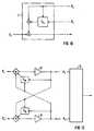
- the hearing aid 1shown schematically in FIG. 1, records sound signals via a microphone 2 or further microphones 2 '. This acoustic information is converted into electrical signals in the microphone or microphones. After signal processing in an amplification and transmission part 4, the electrical signal is fed to a receiver 3 as an output converter.
- the amplifier and transmission part 4further comprises a neural structure 5 such that, for the purpose of improved signal processing, in particular for improved separation of the useful signals from the noise, signals of the signal path from at least one microphone 2, 2 'to the listener 3 via the neural Structure 5 managed and processed in it.
- a data carrier 6is assigned to the neural structure 5, in which configuration information of the neural structure is programmable or permanently stored.
- a signal processing unit 9 for preprocessing the input signal into a plurality of sub-signals 10, 10 ', 10''is connected upstream, the sub-signals then being processed further in the neural structure.
- the neural structure 5Taking into account the configuration information of the data carrier 6, the neural structure 5 generates an output signal from the processed partial signals 10, 10 ', 10'', in particular a useful signal separated from the noise, which is then further processed, for example, in known components of the amplifier and transmission unit 4 and via the final amplifier 4''' can be fed to the receiver 3.
- Neural structuresconsist of many similar elements or neurons 19. The function of the neural structure as a whole essentially depends on the way in which these neurons are interconnected.
- the course of the output function Wrepresents a step function at the threshold value s.
- the output function Whas a continuous course around the threshold value s.
- FIG. 4bshows a continuous, so-called sigmoid curve of the output variable with limitation to a maximum and a minimum output value.
- FIG. 4cshows a linear course in the transition area.
- the signals which are processed by the neural structurecan be designed as voltage signals, current signals or as frequency-variable pulse signals.
- the signalmay have to be converted into a continuous current or voltage signal and back again at some points in the neural structure with the aid of suitable circuits.
- FIG. 5shows the exemplary connection of three neurons 19 to the typical structure of a single-layer feedback network with the inputs e i (t) and the outputs a j (t + ⁇ T).
- Figure 6shows an example of the structure of a multilayer feedback-free network. Depending on the function of the neural structure to be implemented, one or the other network structure must be used. Mixed forms of both structures are also possible.
- the function of a neural structure as a wholeis essentially determined by the network structure and by the weighting functions of the input signals on each neuron 19. These parameters can be permanently set through the implementation in terms of circuitry if constant behavior is desired. If, on the other hand, a change in behavior should be possible, some or all of these parameters must be programmable. Your respective values must then be stored in a configuration memory or data medium 6 can be saved. The individual memory elements can be arranged in a concentrated form or locally assigned to the respective neuron.
- the stored parameterscan be modified either by external programming of the memory elements and / or by an algorithm implemented in the circuit. Modification is also possible during the ongoing operation of the neural structure.
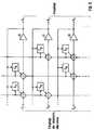
- Figure 7shows an example of the circuitry implementation of a single-layer feedback network.
- Amplifiers 24 with complementary outputsact as threshold elements.
- the connections (synapses) between the outputs and inputs of the neuronsare weighted using the guide values R ij .
- the addition of the input signals for each neuronhappens in the circuit nodes at the input of each amplifier.
- the output signals of the amplifiers and thus the neural structureare the voltage signals U i .
- E1 to e4denote the inputs of the circuit and a1 to a4 denote inverting and non-inverting outputs of the circuit.
- FIG. 8shows a possible circuit implementation of a synapse (weighted input of a neuron) with programmable connection strength. Only the connection strengths +1, -1 and 0 are possible and the signals to be transmitted from this synapse can only assume the logical values 0 and 1. If both memory cells 25, 26 are programmed so that they block the respective associated switching transistor 27 or 28, output a is independent of input e; the synapse therefore represents an interruption (connection strength 0). If, on the other hand, the memory cell 25 is programmed so that it closes the switch and the memory cell 26 so that it opens the associated switch, then a current flows from output a (logic 1) when the Input is logic 1 and no current (logic 0) if the input is logic 0.
- the synapseacts as a connection of strength +1. If both memory cells 25, 26 are programmed inversely for this purpose, the inverse logic behavior results. The synapse then acts as a connection of strength -1. V dd indicates the circuit connection to the supply voltage in the drawing.
- FIG. 9shows a possible implementation of a programmable synapse with variable connection strength. It works on the principle of the multiplier.
- the strength of the synaptic connectionis stored as the difference between two analog voltage values on two capacitors 29, 30.
- An advantageous application of neural structures in the hearing aidis the separation of independent mixed signals, e.g. the separation of the voice signal of a conversation partner from a noise from another source.
- the neural structureneeds as many independent signal inputs as there are independent signals to be separated from one another. This can be achieved in the hearing aid by using a plurality of microphones, these preferably being arranged in such a way that the signals to be separated arrive at the two microphones with as different a strength as possible.
- FIG. 11generally shows how a single-layer feedback network structure can be used to separate the signals.
- the neural structurereceives the signals from the individual microphones and to the Outputs A1, A2, A3 ... are after a certain learning time the separate signals from each other for further processing or output to the listener 3. It makes sense to process or output only one (desired) output signal, while the other output signals are discarded.
- a suitable size S ij or functionindependently determines the degree of connection strength for each synapse 7.
- the size S13, S12, S21, S23, S31, S32 ... or generally S ijrepresents the learning function of the neural structure.
- a possible realization of the variable connection strength of the synapse 7is shown in Figure 10.
- the input signal E i (t)the returned output signal A j (t) multiplied by a quantity S ij (t) is added.
- S ijcan be stored permanently in order to be able to call them up again and again for the same signal processing function, for example by selecting a listening situation, or the learning process of the neural structure can be restarted by the user in order to process the signal adapt to the new acoustic environment.
- the learning process of the neural structurecan be restarted by the user in order to process the signal adapt to the new acoustic environment.
- an ongoing automatic adaptation of the neural structurepossible in order to continuously adapt to minor changes in the acoustic environment.
- the neural structureis designed as a single-layer feedback network which has two inputs E1, E2 and comprises two synapses, the limiting amplifiers 31 being provided in the signal paths of the inputs E1, E2 to the two outputs A1, A2 and each Output signal multiplied by a variable S ij and added to the respective other input signal, and furthermore the variable S ij is a function of the two output signals.
Landscapes
- Physics & Mathematics (AREA)
- Engineering & Computer Science (AREA)
- Artificial Intelligence (AREA)
- Automation & Control Theory (AREA)
- Evolutionary Computation (AREA)
- Fuzzy Systems (AREA)
- Mathematical Physics (AREA)
- Software Systems (AREA)
- Health & Medical Sciences (AREA)
- General Health & Medical Sciences (AREA)
- Neurosurgery (AREA)
- Otolaryngology (AREA)
- Acoustics & Sound (AREA)
- Signal Processing (AREA)
- Amplifiers (AREA)
- Circuit For Audible Band Transducer (AREA)
Abstract
Description
Translated fromGermanDie Erfindung betrifft ein programmierbares Hörgerät mit einem in seinen Übertragungseigenschaften zwischen wenigstens einem Mikrofon und einem Hörer auf verschiedene Übertragungscharakteristika einstellbaren Verstärker- und Übertragungsteil.The invention relates to a programmable hearing aid with an amplifier and transmission part which can be adjusted in terms of its transmission properties between at least one microphone and a receiver to different transmission characteristics.
Aus der EP-B-0 064 042 ist eine Schaltungsanordnung für ein Hörgerät bekannt, bei dem in dem Hörgerät selbst in einem Speicher beispielsweise die Parameter mehrerer verschiedener Umgebungssituationen abgespeichert sind. Durch Betätigen eines Schalters wird eine erste Gruppe von Parametern abgerufen und steuert über eine Steuereinheit einen zwischen Mikrofon und Hörer eingeschalteten Signalprozessor, der dann eine erste, für eine vorgesehene Umgebungssituation bestimmte Übertragungsfunktion einstellt. Über einen Schalter können so die Übertragungsfunktionen mehrerer gespeicherter Signalübertragungsprogramme nacheinander abgerufen werden, bis die gerade zur gegebenen Umgebungssituation passende Übertragungsfunktion gefunden ist.EP-B-0 064 042 discloses a circuit arrangement for a hearing device in which, for example, the parameters of a number of different environmental situations are stored in a memory in the hearing device itself. By actuating a switch, a first group of parameters is called up and controls, via a control unit, a signal processor connected between the microphone and the handset, which then sets a first transmission function intended for an intended environmental situation. The transmission functions of several stored signal transmission programs can be called up in succession via a switch until the transmission function that is just right for the given environmental situation is found.
Folglich ist es bekannt, Hörgeräte an den individuellen Hörverlust des zu versorgenden Hörgeräteträgers anzupassen. Dabei wird auch eine Einstellung des Hörgerätes für verschiedene Hörsituationen vorgesehen. Programmierbare Hörgeräte bieten eine Vielzahl von einstellbaren Parametern, welche die möglichst optimale Anpassung des elektroakustischen Verhaltens des Hörgerätes an den zu kompensierenden Gehörschaden ermöglichen sollen.It is therefore known to adapt hearing aids to the individual hearing loss of the hearing device wearer to be supplied. A setting of the hearing aid is also provided for different listening situations. Programmable hearing aids offer a large number of adjustable parameters which are intended to enable the electro-acoustic behavior of the hearing aid to be optimally adapted to the hearing damage to be compensated for.
Aufgabe der Erfindung ist es, ein programmierbares Hörgerät zu schaffen, das sich durch eine verbesserte Signalverarbeitung auszeichnet, die insbesondere eine verbesserte Trennung der Nutzsignale vom Störgeräusch ermöglicht.The object of the invention is to provide a programmable hearing aid which is characterized by improved signal processing distinguished, which enables in particular an improved separation of the useful signals from the noise.
Erfindungsgemäß wird diese Aufgabe bei einem Hörgerät der eingangs genannten Art dadurch gelöst, daß Signale des Signalpfades vom Mikrofon zum Hörer über eine neuronale Struktur geführt und darin bearbeitet werden. Der Einsatz von neuronalen Strukturen ermöglicht neuartige Methoden und Algorithmen der Signalverarbeitung im Hörgerät. Unter anderem wird hiermit die bessere Trennung von unterschiedlichen Signalen, also z.B. von Nutzsignalen und Störgeräusch, möglich. Das Verhalten der Signalverarbeitung kann dabei fest bzw. programmierbar sein oder variabel, um sich während des Betriebs dem zu verarbeitenden Signal laufend anzupassen.According to the invention, this object is achieved in a hearing device of the type mentioned in the introduction in that signals of the signal path from the microphone to the listener are routed through a neural structure and processed therein. The use of neural structures enables novel methods and algorithms for signal processing in the hearing aid. Among other things, this improves the separation of different signals, e.g. of useful signals and noise, possible. The behavior of the signal processing can be fixed or programmable or variable in order to continuously adapt to the signal to be processed during operation.
In vorteilhafter Ausbildung der Erfindung erfolgt in der neuronalen Struktur eine Trennung von Nutz- und Störsignalen. Die neuronale Struktur verarbeitet mehrere Eingangssignale gleichzeitig. Daraus ergeben sich für die Anwendung im Hörgerät zwei mögliche Ansätze:
- Es wird nur ein Mikrofon eingesetzt und das damit aufgenommene Signal wird, eventuell nach vorheriger anderweitiger Verarbeitung im Signalpfad, durch eine geeignete Vorverarbeitung in mehrere Einzelsignale verwandelt, z.B. durch Aufteilung in verschiedene Frequenzbereiche. Diese Einzelsignale werden dann der neuronalen Struktur zugeführt.
- Es wird mehr als ein Mikrofon eingesetzt und diese einzelnen Signale werden, eventuell nach vorheriger anderweitiger Verarbeitung im Signalpfad, der neuronalen Struktur zugeführt.
- Only one microphone is used and the signal recorded with it, possibly after prior processing in the signal path, is converted into several individual signals by suitable preprocessing, for example by division into different frequency ranges. These individual signals are then fed to the neural structure.
- More than one microphone is used and these individual signals are fed to the neural structure, possibly after other processing in the signal path beforehand.
Vorteilhafte Ausführungsformen der Erfindung sind durch die Patentansprüche gekennzeichnet.Advantageous embodiments of the invention are characterized by the claims.
Weitere Vorteile und Einzelheiten der Erfindung werden nachfolgend anhand der in den Figuren dargestellten Ausführungsbeispiele näher erläutert.Further advantages and details of the invention are explained in more detail below with reference to the exemplary embodiments shown in the figures.
Es zeigen:
Figur 1 ein Blockschaltbild eines erfindungsgemäßen Hörgerätes,Figur 2 einen Signalpfad von einem Mikrofon über eine Signalaufbereitung und eine neuronale Struktur zum Hörer eines Hörgerätes gemäßFigur 1,- Figur 3 ein Blockschaltbild eines einzelnen Neurons,
- Figuren 4a, 4b, 4c Beispiele für mögliche Schwellenwertverläufe der Ausgabefunktion W gemäß Figur 3,
Figur 5 ein einlagiges, rückgekoppeltes Netz mit beispielhafter Verschaltung von drei Neuronen,Figur 6 ein mehrlagiges, rückkopplungsfreies Netz mit beispielhafter Verschaltung von elf Neuronen in drei Lagen,- Figur 7 ein Schaltungsbeispiel für die schaltungstechnische Realisierung eines einlagigen rückgekoppelten Netzes gemäß
Figur 5, - Figur 8 eine mögliche Schaltung zur Realisierung einer Synapse mit programmierbarer Verbindungsstärke,
Figur 9 eine Ausführung einer Schaltung für eine Synapse mit programmierbarer variabler Verbindungsstärke,Figur 10 ein Blockschaltbild einer Synapse 7 mit variabler Verbindungsstärke zwischen einem Eingang Ei und einem Ausgang Aj des Netzes,- Figur 11 ein Schaltungsbeispiel eines einlagigen rückgekoppelten Netzes zur Trennung von vermischten unabhängigen Signalen, beispielsweise von drei Eingangssignalen E₁, E₂, E₃ zu drei Ausgangssignalen A₁, A₂, A₃,
- Figur 12 ein Schaltungsbeispiel eines einlagigen rückgekoppelten Netzes zur Trennung von zwei vermischten unabhängigen Signalen, nämlich zwei Eingangssignalen E₁, E₂ zu zwei Ausgangssignalen A₁, A₂.
- FIG. 1 shows a block diagram of a hearing device according to the invention,
- FIG. 2 shows a signal path from a microphone via signal processing and a neural structure to the listener of a hearing device according to FIG. 1,
- FIG. 3 shows a block diagram of an individual neuron,
- FIGS. 4a, 4b, 4c examples of possible threshold value profiles for the output function W according to FIG. 3,
- FIG. 5 shows a single-layer, feedback network with an exemplary connection of three neurons,
- FIG. 6 shows a multi-layer, feedback-free network with exemplary connection of eleven neurons in three layers,
- FIG. 7 shows a circuit example for the implementation of a single-layer feedback network according to FIG. 5,
- FIG. 8 shows a possible circuit for realizing a synapse with programmable connection strength,
- FIG. 9 shows an embodiment of a circuit for a synapse with programmable variable connection strength,
- FIG. 10 shows a block diagram of a synapse 7 with variable connection strength between an input Ei and an output Aj of the network,
- Figure 11 is a circuit example of a single-layer feedback network for separating mixed independent signals, for example from three input signals E₁, E₂, E₃ to three output signals A₁, A₂, A₃,
- Figure 12 is a circuit example of a single-layer feedback network for separating two mixed independent signals, namely two input signals E₁, E₂ to two output signals A₁, A₂.
Das in Figur 1 schematisch dargestellte erfindungsgemäße Hörgerät 1 nimmt über ein Mikrofon 2 oder weitere Mikrofone 2' Schallsignale auf. Diese akustische Information wird im Mikrofon bzw. in den Mikrofonen in elektrische Signale umgesetzt. Nach einer Signalbearbeitung in einem Verstärkungs- und Übertragungsteil 4 wird das elektrische Signal einem Hörer 3 als Ausgangswandler zugeführt. Im Ausführungsbeispiel sind im Verstärker- und Übertragungsteil 4 lediglich noch Vorverstärker 4', 4'' und ein Endverstärker 4''' angedeutet. Nach der Erfindung umfaßt das Verstärker- und Übertragungsteil 4 ferner eine neuronale Struktur 5, derart, daß zwecks einer verbesserten Signalverarbeitung, insbesondere zur verbesserten Trennung der Nutzsignale vom Störgeräusch, Signale des Signalpfades von wenigstens einem Mikrofon 2, 2' zum Hörer 3 über die neuronale Struktur 5 geführt und darin bearbeitet werden. Der neuronalen Struktur 5 ist ein Datenträger 6 zugeordnet, in dem Konfigurationsinformation der neuronalen Struktur programmierbar oder fest abgespeichert ist.The
In vorteilhafter Ausführung ist gemäß Figur 2 im Signalpfad vom Mikrofon 2 der neuronalen Struktur 5 eine Signalaufbereitung 9 zur Vorverarbeitung des Eingangssignals in mehrere Teilsignale 10, 10', 10'' vorgeschaltet, wobei dann die Teilsignale in der neuronalen Struktur weiter bearbeitet werden. Unter Berücksichtigung der Konfigurationsinformation des Datenträgers 6 erzeugt die neuronale Struktur 5 aus den aufbereiteten Teilsignalen 10, 10', 10'' ein Ausgangssignal, insbesondere ein vom Störgeräusch getrenntes Nutzsignal, welches dann beispielsweise in bekannten Komponenten der Verstärker- und Übertragungseinheit 4 weiter bearbeitet und über den Endverstärker 4''' dem Hörer 3 zugeführt werden kann.In an advantageous embodiment, according to FIG. 2, in the signal path from the
Anhand der Figuren 3-9 werden Beispiele zur Realisierung der neuronalen Struktur beschrieben.Examples for realizing the neural structure are described with reference to FIGS. 3-9.
Neuronale Strukturen bestehen aus vielen gleichartigen Elementen bzw. Neuronen 19. Die Funktion der neuronalen Struktur als Ganzes hängt im wesentlichen von der Art der Verschaltung dieser Neuronen untereinander ab.Neural structures consist of many similar elements or
Figur 3 zeigt das Blockschaltbild eines einzelnen Neurons 19. Das Neuron erzeugt das Ausgangssignal aj(t+ΔT) zum Zeitpunkt t+ΔT aus theoretisch beliebig vielen Eingangssignalen ei(t) zum Zeitpunkt t. Seine Funktion läßt sich in drei Grundfunktionen zerlegen:
- Propagierungsfunktion

- Aktivierungsfunktion

- Ausgangsfunktion W:w(t) Sie nimmt eine Schwellenwertbildung vor. Dabei sind zwei grundsätzliche Arten der Schwellenwertbildung möglich.


- Propagation function
- Activation function
- Output function W: w (t) It creates a threshold value. Two basic types of threshold value formation are possible.
Nach Figur 4a stellt der Verlauf der Ausgabefunktion W eine Sprungfunktion am Schwellenwert s dar.According to FIG. 4a, the course of the output function W represents a step function at the threshold value s.
Nach den Figuren 4b und 4c besitzt die Ausgabefunktion W einen stetigen Verlauf um den Schwellenwert s. In Figur 4b ist ein stetiger, sogenannter sigmoider Verlauf der Ausgangsgröße mit Begrenzung auf einen maximalen und einen minimalen Ausgangswert dargestellt. Eine häufig verwendete Kennlinie ist hierbei das Sigmoid:
Die Signale, welche von der neuronalen Struktur verarbeitet werden, können als Spannungssignale, Stromsignale oder als frequenzvariable Impulssignale ausgeführt sein. Im letzteren Fall muß das Signal eventuell an manchen Stellen der neuronalen Struktur mit Hilfe geeigneter Schaltungen in ein kontinuierliches Strom- oder Spannungssignal und wieder zurück umgewandelt werden.The signals which are processed by the neural structure can be designed as voltage signals, current signals or as frequency-variable pulse signals. In the latter case, the signal may have to be converted into a continuous current or voltage signal and back again at some points in the neural structure with the aid of suitable circuits.
Figur 5 zeigt die beispielhafte Verschaltung von drei Neuronen 19 zur typischen Struktur eines einlagigen rückgekoppelten Netzes mit den Eingängen ei(t) und den Ausgängen aj(t+ΔT).FIG. 5 shows the exemplary connection of three
Figur 6 zeigt beispielhaft die Struktur eines mehrlagigen rückkopplungsfreien Netzes. Je nach zu implementierender Funktion der neuronalen Struktur ist die eine oder andere Netzstruktur anzuwenden. Auch Mischformen aus beiden Strukturen sind dabei möglich.Figure 6 shows an example of the structure of a multilayer feedback-free network. Depending on the function of the neural structure to be implemented, one or the other network structure must be used. Mixed forms of both structures are also possible.
Die Funktion einer neuronalen Struktur im Ganzen wird im wesentlichen von der Netzstruktur und von den Gewichtungsfunktionen der Eingangssignale an jedem Neuron 19 bestimmt. Diese Parameter können durch die schaltungstechnische Realisierung fest eingestellt werden, wenn ein immer gleichbleibendes Verhalten erwünscht ist. Soll dagegen eine Veränderung des Verhaltens möglich sein, so sind einige oder alle dieser Parameter programmierbar auszuführen. Ihre jeweiligen Werte müssen dann in einem Konfigurationsspeicher bzw. Datenträger 6 gespeichert werden. Hierbei können die einzelnen Speicherelemente in konzentrierter Form angeordnet sein oder lokal dem jeweiligen Neuron zugeordnet sein.The function of a neural structure as a whole is essentially determined by the network structure and by the weighting functions of the input signals on each
Die Modifikation der gespeicherten Parameter kann entweder durch externes Programmieren der Speicherelemente geschehen und/oder durch einen in der Schaltung implementierten Algorithmus. Hierbei ist auch die Modifikation während des laufenden Betriebs der neuronalen Struktur möglich.The stored parameters can be modified either by external programming of the memory elements and / or by an algorithm implemented in the circuit. Modification is also possible during the ongoing operation of the neural structure.
Figur 7 zeigt ein Beispiel für die schaltungstechnische Realisierung eines einlagigen rückgekoppelten Netzes. Als Schwellenelemente wirken Verstärker 24 mit komplementären Ausgängen. Die Gewichtung der Verbindungen (Synapsen) zwischen den Aus- und Eingängen der Neuronen erfolgt über die Leitwerte Rij. Die Addition der Eingangssignale für jedes Neuron (Ströme
Figur 8 zeigt eine mögliche schaltungstechnische Realisierung einer Synapse (gewichteter Eingang eines Neurons) mit programmierbarer Verbindungsstärke. Hierbei sind nur die Verbindungsstärken +1, -1 und 0 möglich und die von dieser Synapse zu übertragenden Signale können nur die logischen Werte 0 und 1 annehmen. Sind beide Speicherzellen 25, 26 so programmiert, daß sie den jeweiligen zugehörigen Schalttransistor 27 bzw. 28 sperren, so ist der Ausgang a unabhängig vom Eingang e; die Synapse stellt also eine Unterbrechung dar (Verbindungsstärke 0). Ist dagegen die Speicherzelle 25 so programmiert, daß sie den Schalter schließt und die Speicherzelle 26 so, daß sie den zugehörigen Schalter öffnet, so fließt aus dem Ausgang a dann ein Strom (logisch 1), wenn der Eingang logisch 1 ist, und kein Strom (logisch 0), wenn der Eingang logisch 0 ist. Die Synapse wirkt also als Verbindung der Stärke +1. Sind beide Speicherzellen 25, 26 hierzu invers programmiert, so ergibt sich das inverse logische Verhalten. Die Synapse wirkt dann als Verbindung der Stärke -1. Vdd gibt in der Zeichnung den Schaltungsanschluß zur Versorgungsspannung an.FIG. 8 shows a possible circuit implementation of a synapse (weighted input of a neuron) with programmable connection strength. Only the connection strengths +1, -1 and 0 are possible and the signals to be transmitted from this synapse can only assume the
Figur 9 zeigt eine mögliche Realisierung einer programmierbaren Synapse mit variabler Verbindungsstärke. Sie arbeitet nach dem Prinzip des Multiplizierers. Die Stärke der synaptischen Verbindung wird als Differenz zweier analoger Spannungswerte auf zwei Kapazitäten 29, 30 gespeichert. Das Ausgangssignal (Strom Iout) ergibt sich als Produkt des Eingangssignals (Spannung Vin) multipliziert mit der auf den Kapazitäten gespeicherten Spannungsdifferenz (
Eine vorteilhafte Anwendung von neuronalen Strukturen im Hörgerät stellt die Trennung von unabhängigen gemischten Signalen dar, also z.B. die Trennung des Sprachsignals eines Gesprächspartners von einem Störgeräusch aus einer anderen Quelle. Hierzu benötigt die neuronale Struktur genau so viele unabhängige Signaleingänge wie unabhängige Signale voneinander getrennt werden müssen. Dies kann im Hörgerät durch den Einsatz von mehreren Mikrofonen erreicht werden, wobei diese bevorzugt so anzuordnen sind, daß die zu trennenden Signale an beiden Mikrofonen mit möglichst unterschiedlicher Stärke eintreffen.An advantageous application of neural structures in the hearing aid is the separation of independent mixed signals, e.g. the separation of the voice signal of a conversation partner from a noise from another source. To do this, the neural structure needs as many independent signal inputs as there are independent signals to be separated from one another. This can be achieved in the hearing aid by using a plurality of microphones, these preferably being arranged in such a way that the signals to be separated arrive at the two microphones with as different a strength as possible.
Figur 11 zeigt allgemein, wie zur Trennung der Signale eine einlagige rückgekoppelte Netzstruktur verwendet werden kann. An den Eingängen E₁, E₂, E₃... erhält die neuronale Struktur die Signale der einzelnen Mikrofone zugeführt und an den Ausgängen A₁, A₂, A₃... stehen nach einer bestimmten Lernzeit die voneinander getrennten unabhängigen Signale zur Weiterverarbeitung oder zur Ausgabe auf den Hörer 3 an. Sinnvollerweise erfolgt die Weiterverarbeitung oder Ausgabe nur von einem (gewünschten) Ausgangssignal, während die anderen Ausgangssignale verworfen werden.FIG. 11 generally shows how a single-layer feedback network structure can be used to separate the signals. At the inputs E₁, E₂, E₃ ... the neural structure receives the signals from the individual microphones and to the Outputs A₁, A₂, A₃ ... are after a certain learning time the separate signals from each other for further processing or output to the listener 3. It makes sense to process or output only one (desired) output signal, while the other output signals are discarded.
Eine geeignete Größe Sij bzw. Funktion bestimmt für jede Synapse 7 unabhängig den Grad der Verbindungsstärke. Die Größe S₁₃, S₁₂, S₂₁, S₂₃, S₃₁, S₃₂ ... oder allgemein Sij stellt hierbei die Lernfunktion der neuronalen Struktur dar. Eine mögliche Realisierung der variablen Verbindungsstärke der Synapse 7 zeigt Figur 10. Zum Eingangssignal Ei(t) wird das mit einer Größe Sij(t) multiplizierte zurückgeführte Ausgangssignal Aj(t) addiert. Die Größe Sij(t) wiederum ist eine Funktion der beiden Größen Ai(t) und Aj(t), wobei im allgemeinen in die Berechnung von
Im einfachsten Fall, für die Trennung von zwei unabhängigen Signalen, reduziert sich die neuronale Struktur, wie in Figur 12 dargestellt. Eine mögliche Realisierung der Größen Sij(t) für die beiden Synapsen lautet:


Eine vorteilhafte Realisierung der Signalverarbeitung im Hörgerät kann in der Kombination der Prinzipien der neuronalen Strukturen und der Fuzzy-Logik bestehen. Hierbei sind verschiedene Ansätze möglich:
- Die Verwendung von Fuzzy-Logik bei der Vorverarbeitung des Eingangssignals zur Gewinnung
von mehreren Teilsignalen 10, 10', 10'' ... für die neuronale Struktur.Wie Figur 2 zeigt, ist der neuronalen Struktur 5eine Signalaufbereitung 9 vorgeschaltet, die nach dem Prinzip der Fuzzy-Logik arbeitet. - Die Verwendung von Fuzzy-Logik bei der Auswahl von einem der drei oder mehreren durch die neuronale Struktur separierten Signale. Wie in Figur 12 schematisch dargestellt ist, ist der neuronalen Struktur eine Entscheidungsmittelkomponente 11 zur Auswahl des nutzbaren Ausgangssignals zugeordnet, welche nach dem Prinzip der Fuzzy-Logik arbeitet.
- The use of fuzzy logic in the preprocessing of the input signal to obtain a plurality of
partial signals 10, 10 ', 10''... for the neural structure. As FIG. 2 shows, theneural structure 5 is preceded by asignal processing unit 9, which works on the principle of fuzzy logic. - The use of fuzzy logic when selecting one of the three or more signals separated by the neural structure. As shown schematically in FIG. 12, a decision means component 11 for selecting the usable output signal is assigned to the neural structure, which component works on the principle of fuzzy logic.
In den Figuren 11, 12 sind in den neuronalen Netzen noch begrenzende Verstärker 31 eingezeichnet. Gemäß Figur 12 ist die neuronale Struktur als einlagig rückgekoppeltes Netz ausgeführt, welches zwei Eingänge E₁, E₂ aufweist und zwei Synapsen umfaßt, wobei in den Signalpfaden der Eingänge E₁, E₂ zu den beiden Ausgängen A₁, A₂ die begrenzenden Verstärker 31 vorgesehen sind und wobei jedes Ausgangssignal mit einer Größe Sij multipliziert und zu dem jeweils anderen Eingangssignal addiert wird und wobei ferner die Größe Sij jeweils eine Funktion der beiden Ausgangssignale ist.In FIGS. 11, 12,
Die prinzipielle Funktionsweise sowie eine mögliche schaltungstechnische Realisierung der für die Fuzzy-Logik notwendigen Funktionen Fuzzyfizierung, Inferenzbildung und Defuzzyfizierung ist in der europäischen Patentanmeldung 94104619.5 beschrieben.The principle of operation and a possible circuitry implementation of the functions fuzzy logic, inference formation and defuzzification necessary for the fuzzy logic is described in European patent application 94104619.5.
Wesentliche Vorteile der Erfindung ergeben sich aus einer verbesserten Signalverarbeitung im Hörgerät durch den Einsatz neuer Algorithmen. Ferner durch eine verbesserte Trennung von Nutzsignalen und Störgeräusch durch die Möglichkeit, unabhängige vermischte Signale zu trennen und schließlich durch kontinuierliche Optimierung der Signalverarbeitungscharakteristik durch "Lernen" im laufenden Betrieb.Significant advantages of the invention result from improved signal processing in the hearing aid through the use of new algorithms. Furthermore, through an improved separation of useful signals and noise from the possibility of separating independent mixed signals and finally through continuous optimization of the signal processing characteristics through "learning" during operation.
Claims (16)
Translated fromGerman
Priority Applications (2)
| Application Number | Priority Date | Filing Date | Title |
|---|---|---|---|
| EP94117795AEP0712261A1 (en) | 1994-11-10 | 1994-11-10 | Programmable hearing aid |
| US08/515,907US5754661A (en) | 1994-11-10 | 1995-08-16 | Programmable hearing aid |
Applications Claiming Priority (1)
| Application Number | Priority Date | Filing Date | Title |
|---|---|---|---|
| EP94117795AEP0712261A1 (en) | 1994-11-10 | 1994-11-10 | Programmable hearing aid |
Publications (1)
| Publication Number | Publication Date |
|---|---|
| EP0712261A1true EP0712261A1 (en) | 1996-05-15 |
Family
ID=8216450
Family Applications (1)
| Application Number | Title | Priority Date | Filing Date |
|---|---|---|---|
| EP94117795AWithdrawnEP0712261A1 (en) | 1994-11-10 | 1994-11-10 | Programmable hearing aid |
Country Status (2)
| Country | Link |
|---|---|
| US (1) | US5754661A (en) |
| EP (1) | EP0712261A1 (en) |
Cited By (8)
| Publication number | Priority date | Publication date | Assignee | Title |
|---|---|---|---|---|
| WO1998054928A3 (en)* | 1997-05-27 | 1999-03-04 | Eugene Alexandrescu | Hearing instrument with head activated switch |
| DE19844748A1 (en)* | 1998-09-29 | 1999-10-07 | Siemens Audiologische Technik | Method of preparing directional microphone characteristic, especially for listening device |
| US6044163A (en)* | 1996-06-21 | 2000-03-28 | Siemens Audiologische Technik Gmbh | Hearing aid having a digitally constructed calculating unit employing a neural structure |
| EP1023647A4 (en)* | 1997-10-15 | 2000-12-06 | Beltone Electronics Corp | A neurofuzzy based device for programmable hearing aids |
| DE19948907A1 (en)* | 1999-10-11 | 2001-02-01 | Siemens Audiologische Technik | Signal processing in hearing aid |
| WO2000076268A3 (en)* | 1999-06-02 | 2001-05-17 | Siemens Audiologische Technik | Hearing aid device, comprising a directional microphone system and a method for operating a hearing aid device |
| US6674867B2 (en) | 1997-10-15 | 2004-01-06 | Belltone Electronics Corporation | Neurofuzzy based device for programmable hearing aids |
| WO2022081260A1 (en)* | 2020-10-16 | 2022-04-21 | Starkey Laboratories, Inc. | Hearing device with dynamic neural networks for sound enhancement |
Families Citing this family (28)
| Publication number | Priority date | Publication date | Assignee | Title |
|---|---|---|---|---|
| US6449377B1 (en)* | 1995-05-08 | 2002-09-10 | Digimarc Corporation | Methods and systems for watermark processing of line art images |
| US6611607B1 (en)* | 1993-11-18 | 2003-08-26 | Digimarc Corporation | Integrating digital watermarks in multimedia content |
| US6614914B1 (en) | 1995-05-08 | 2003-09-02 | Digimarc Corporation | Watermark embedder and reader |
| US6944298B1 (en) | 1993-11-18 | 2005-09-13 | Digimare Corporation | Steganographic encoding and decoding of auxiliary codes in media signals |
| US5748763A (en)* | 1993-11-18 | 1998-05-05 | Digimarc Corporation | Image steganography system featuring perceptually adaptive and globally scalable signal embedding |
| US6560349B1 (en)* | 1994-10-21 | 2003-05-06 | Digimarc Corporation | Audio monitoring using steganographic information |
| US6760463B2 (en)* | 1995-05-08 | 2004-07-06 | Digimarc Corporation | Watermarking methods and media |
| US6035177A (en)* | 1996-02-26 | 2000-03-07 | Donald W. Moses | Simultaneous transmission of ancillary and audio signals by means of perceptual coding |
| EP0964603A1 (en)* | 1998-06-10 | 1999-12-15 | Oticon A/S | Method of sound signal processing and device for implementing the method |
| WO1999009799A2 (en)* | 1998-11-24 | 1999-03-04 | Phonak Ag | Hearing aid |
| AU766629B2 (en) | 1999-10-14 | 2003-10-23 | Phonak Ag | Method for adapting a hearing device and hearing device |
| US6522988B1 (en)* | 2000-01-24 | 2003-02-18 | Audia Technology, Inc. | Method and system for on-line hearing examination using calibrated local machine |
| US6633202B2 (en) | 2001-04-12 | 2003-10-14 | Gennum Corporation | Precision low jitter oscillator circuit |
| US6937738B2 (en)* | 2001-04-12 | 2005-08-30 | Gennum Corporation | Digital hearing aid system |
| ES2258575T3 (en)* | 2001-04-18 | 2006-09-01 | Gennum Corporation | MULTIPLE CHANNEL HEARING INSTRUMENT WITH COMMUNICATION BETWEEN CHANNELS. |
| CA2382358C (en)* | 2001-04-18 | 2007-01-09 | Gennum Corporation | Digital quasi-rms detector |
| US20020191800A1 (en)* | 2001-04-19 | 2002-12-19 | Armstrong Stephen W. | In-situ transducer modeling in a digital hearing instrument |
| DK1284587T3 (en)* | 2001-08-15 | 2011-10-31 | Sound Design Technologies Ltd | Reconfigurable low energy hearing aid |
| US7889879B2 (en)* | 2002-05-21 | 2011-02-15 | Cochlear Limited | Programmable auditory prosthesis with trainable automatic adaptation to acoustic conditions |
| AUPS247002A0 (en)* | 2002-05-21 | 2002-06-13 | Hearworks Pty Ltd | Programmable auditory prosthesis with trainable automatic adaptation to acoustic conditions |
| DE10347211A1 (en)* | 2003-10-10 | 2005-05-25 | Siemens Audiologische Technik Gmbh | Method for training and operating a hearing aid and corresponding hearing aid |
| DK1691572T3 (en)* | 2005-02-09 | 2019-10-21 | Oticon As | Method and system for training a hearing aid using a self-organizing mapping |
| DE602006014572D1 (en)* | 2005-10-14 | 2010-07-08 | Gn Resound As | OPTIMIZATION FOR HEARING EQUIPMENT PARAMETERS |
| WO2008154706A1 (en)* | 2007-06-20 | 2008-12-24 | Cochlear Limited | A method and apparatus for optimising the control of operation of a hearing prosthesis |
| DK3082350T3 (en)* | 2015-04-15 | 2019-04-23 | Starkey Labs Inc | USER INTERFACE WITH REMOTE SERVER |
| US11270198B2 (en)* | 2017-07-31 | 2022-03-08 | Syntiant | Microcontroller interface for audio signal processing |
| CN113228710B (en)* | 2018-12-21 | 2024-05-24 | 大北欧听力公司 | Sound source separation in a hearing device and related methods |
| DE102019206743A1 (en)* | 2019-05-09 | 2020-11-12 | Sonova Ag | Hearing aid system and method for processing audio signals |
Citations (5)
| Publication number | Priority date | Publication date | Assignee | Title |
|---|---|---|---|---|
| FR2562789A1 (en)* | 1984-04-11 | 1985-10-18 | Intech Systems Corp | DIFFERENTIAL HEARING APPARATUS WITH PROGRAMMABLE FREQUENCY RESPONSE |
| EP0250679A2 (en)* | 1986-06-26 | 1988-01-07 | Audimax Corporation | Programmable sound reproducing system |
| WO1991008654A1 (en)* | 1989-11-30 | 1991-06-13 | Nha As | Hearing aid |
| WO1993026037A1 (en)* | 1992-06-05 | 1993-12-23 | United States Department Of Energy | Process for forming synapses in neural networks and resistor therefor |
| EP0579152A1 (en)* | 1992-07-13 | 1994-01-19 | Minnesota Mining And Manufacturing Company | Auditory prosthesis, noise suppression apparatus and feedback suppression apparatus having focused adapted filtering |
Family Cites Families (13)
| Publication number | Priority date | Publication date | Assignee | Title |
|---|---|---|---|---|
| SE428167B (en)* | 1981-04-16 | 1983-06-06 | Mangold Stephan | PROGRAMMABLE SIGNAL TREATMENT DEVICE, MAINLY INTENDED FOR PERSONS WITH DISABILITY |
| DE3431584A1 (en)* | 1984-08-28 | 1986-03-13 | Siemens AG, 1000 Berlin und 8000 München | HOERHILFEGERAET |
| US4903226A (en)* | 1987-08-27 | 1990-02-20 | Yannis Tsividis | Switched networks |
| JP2764277B2 (en)* | 1988-09-07 | 1998-06-11 | 株式会社日立製作所 | Voice recognition device |
| JPH0272398A (en)* | 1988-09-07 | 1990-03-12 | Hitachi Ltd | Audio signal preprocessing device |
| US5179624A (en)* | 1988-09-07 | 1993-01-12 | Hitachi, Ltd. | Speech recognition apparatus using neural network and fuzzy logic |
| US5172417A (en)* | 1989-05-17 | 1992-12-15 | Pioneer Electronic Corporation | Apparatus for controlling acoustical transfer characteristics |
| US4961002A (en)* | 1989-07-13 | 1990-10-02 | Intel Corporation | Synapse cell employing dual gate transistor structure |
| EP0449754B1 (en)* | 1990-03-30 | 1996-09-04 | Shinko Electric Co. Ltd. | Control system for unmanned carrier vehicle |
| US5351200A (en)* | 1991-11-22 | 1994-09-27 | Westinghouse Electric Corporation | Process facility monitor using fuzzy logic |
| JP3056866B2 (en)* | 1992-02-17 | 2000-06-26 | アルパイン株式会社 | Automatic volume control method |
| US5448644A (en)* | 1992-06-29 | 1995-09-05 | Siemens Audiologische Technik Gmbh | Hearing aid |
| DE4419901C2 (en)* | 1994-06-07 | 2000-09-14 | Siemens Audiologische Technik | Hearing aid |
- 1994
- 1994-11-10EPEP94117795Apatent/EP0712261A1/ennot_activeWithdrawn
- 1995
- 1995-08-16USUS08/515,907patent/US5754661A/ennot_activeExpired - Lifetime
Patent Citations (5)
| Publication number | Priority date | Publication date | Assignee | Title |
|---|---|---|---|---|
| FR2562789A1 (en)* | 1984-04-11 | 1985-10-18 | Intech Systems Corp | DIFFERENTIAL HEARING APPARATUS WITH PROGRAMMABLE FREQUENCY RESPONSE |
| EP0250679A2 (en)* | 1986-06-26 | 1988-01-07 | Audimax Corporation | Programmable sound reproducing system |
| WO1991008654A1 (en)* | 1989-11-30 | 1991-06-13 | Nha As | Hearing aid |
| WO1993026037A1 (en)* | 1992-06-05 | 1993-12-23 | United States Department Of Energy | Process for forming synapses in neural networks and resistor therefor |
| EP0579152A1 (en)* | 1992-07-13 | 1994-01-19 | Minnesota Mining And Manufacturing Company | Auditory prosthesis, noise suppression apparatus and feedback suppression apparatus having focused adapted filtering |
Non-Patent Citations (1)
| Title |
|---|
| G.TRAUTZL: "NEURONALE NETZE UNTERSTÜTZEN FUZZY LOGIK TOOL", ELEKTRONIK, vol. 41, no. 2, 21 January 1992 (1992-01-21), GERMANY, pages 100 - 101, XP000381757* |
Cited By (11)
| Publication number | Priority date | Publication date | Assignee | Title |
|---|---|---|---|---|
| US6044163A (en)* | 1996-06-21 | 2000-03-28 | Siemens Audiologische Technik Gmbh | Hearing aid having a digitally constructed calculating unit employing a neural structure |
| WO1998054928A3 (en)* | 1997-05-27 | 1999-03-04 | Eugene Alexandrescu | Hearing instrument with head activated switch |
| EP1023647A4 (en)* | 1997-10-15 | 2000-12-06 | Beltone Electronics Corp | A neurofuzzy based device for programmable hearing aids |
| US6674867B2 (en) | 1997-10-15 | 2004-01-06 | Belltone Electronics Corporation | Neurofuzzy based device for programmable hearing aids |
| US7187778B2 (en) | 1997-10-15 | 2007-03-06 | Beltone Electronics Corporation | Neurofuzzy based device for programmable hearing aids |
| DE19844748A1 (en)* | 1998-09-29 | 1999-10-07 | Siemens Audiologische Technik | Method of preparing directional microphone characteristic, especially for listening device |
| WO2000076268A3 (en)* | 1999-06-02 | 2001-05-17 | Siemens Audiologische Technik | Hearing aid device, comprising a directional microphone system and a method for operating a hearing aid device |
| US7324649B1 (en) | 1999-06-02 | 2008-01-29 | Siemens Audiologische Technik Gmbh | Hearing aid device, comprising a directional microphone system and a method for operating a hearing aid device |
| DE19948907A1 (en)* | 1999-10-11 | 2001-02-01 | Siemens Audiologische Technik | Signal processing in hearing aid |
| WO2022081260A1 (en)* | 2020-10-16 | 2022-04-21 | Starkey Laboratories, Inc. | Hearing device with dynamic neural networks for sound enhancement |
| US12309552B2 (en) | 2020-10-16 | 2025-05-20 | Starkey Laboratories, Inc. | Hearing device with dynamic neural networks for sound enhancement |
Also Published As
| Publication number | Publication date |
|---|---|
| US5754661A (en) | 1998-05-19 |
Similar Documents
| Publication | Publication Date | Title |
|---|---|---|
| EP0712261A1 (en) | Programmable hearing aid | |
| EP0674462B1 (en) | Device for the fitting of programmable hearing aids | |
| DE102019200954A1 (en) | Signal processing device, system and method for processing audio signals | |
| EP3809724B1 (en) | Hearing device and method for operating a hearing device | |
| EP1470735B1 (en) | Method for determining an acoustic environment situation, application of the method and hearing aid | |
| EP0674464A1 (en) | Programmable hearing aid with fuzzy logic controller | |
| DE102006027673A1 (en) | Signal isolator, method for determining output signals based on microphone signals and computer program | |
| EP1912471B1 (en) | Processing of an input signal in a hearing aid | |
| EP0814636A1 (en) | Hearing aid | |
| EP1307072A2 (en) | Method for operating a hearing aid and hearing aid | |
| EP1802171A1 (en) | Signal processing for hearing aids with multiple compression algorithms | |
| DE102019200956A1 (en) | Signal processing device, system and method for processing audio signals | |
| EP0712263B1 (en) | Programmable hearing aid | |
| DE102010041740A1 (en) | Method for signal processing in a hearing aid device and hearing aid device | |
| EP0674463A1 (en) | Programmable hearing aid | |
| EP1432282B1 (en) | Method for adapting a hearing aid to a momentary acoustic environment situation and hearing aid system | |
| DE19624092B4 (en) | Amplification circuit, preferably for analog or digital hearing aids and hearing aids using a corresponding amplification circuit or a corresponding signal processing algorithm | |
| EP0814635B1 (en) | Hearing aid | |
| EP2200341A1 (en) | Method for operating a hearing aid and hearing aid with a source separation device | |
| DE19948907A1 (en) | Signal processing in hearing aid | |
| EP1303166B1 (en) | Method of operating a hearing aid and assembly with a hearing aid | |
| EP0788290A1 (en) | Programmable hearing aid | |
| DE102009004185B3 (en) | Method for converting input signal into output signal in e.g. headphone, involves forming output signal formed from intermediate signals with mixing ratio that depends on result of classification | |
| EP1649719B1 (en) | Device and method for operating voice-assisted systems in motor vehicles | |
| DE69731133T2 (en) | Transmission system for correlated signals |
Legal Events
| Date | Code | Title | Description |
|---|---|---|---|
| PUAI | Public reference made under article 153(3) epc to a published international application that has entered the european phase | Free format text:ORIGINAL CODE: 0009012 | |
| AK | Designated contracting states | Kind code of ref document:A1 Designated state(s):CH DE DK FR LI NL | |
| 17P | Request for examination filed | Effective date:19961120 | |
| 17Q | First examination report despatched | Effective date:20010112 | |
| STAA | Information on the status of an ep patent application or granted ep patent | Free format text:STATUS: THE APPLICATION IS DEEMED TO BE WITHDRAWN | |
| 18D | Application deemed to be withdrawn | Effective date:20011211 |