EP0712200B1 - Power supply outlet - Google Patents
Power supply outletDownload PDFInfo
- Publication number
- EP0712200B1 EP0712200B1EP95308075AEP95308075AEP0712200B1EP 0712200 B1EP0712200 B1EP 0712200B1EP 95308075 AEP95308075 AEP 95308075AEP 95308075 AEP95308075 AEP 95308075AEP 0712200 B1EP0712200 B1EP 0712200B1
- Authority
- EP
- European Patent Office
- Prior art keywords
- voltage
- outlet
- connector
- voltages
- insert member
- Prior art date
- Legal status (The legal status is an assumption and is not a legal conclusion. Google has not performed a legal analysis and makes no representation as to the accuracy of the status listed.)
- Expired - Lifetime
Links
- 238000000034methodMethods0.000claimsdescription13
- 230000001419dependent effectEffects0.000claimsdescription4
- 230000008878couplingEffects0.000claimsdescription2
- 238000010168coupling processMethods0.000claimsdescription2
- 238000005859coupling reactionMethods0.000claimsdescription2
- 238000003780insertionMethods0.000claimsdescription2
- 230000037431insertionEffects0.000claimsdescription2
- 239000004020conductorSubstances0.000description8
- 238000002955isolationMethods0.000description6
- 238000006243chemical reactionMethods0.000description4
- 238000013461designMethods0.000description4
- 238000010586diagramMethods0.000description4
- 239000003990capacitorSubstances0.000description3
- RYGMFSIKBFXOCR-UHFFFAOYSA-NCopperChemical compound[Cu]RYGMFSIKBFXOCR-UHFFFAOYSA-N0.000description2
- 229910052802copperInorganic materials0.000description2
- 239000010949copperSubstances0.000description2
- 239000004065semiconductorSubstances0.000description2
- 101100191136Arabidopsis thaliana PCMP-A2 geneProteins0.000description1
- 101100048260Saccharomyces cerevisiae (strain ATCC 204508 / S288c) UBX2 geneProteins0.000description1
- 238000013459approachMethods0.000description1
- 238000010276constructionMethods0.000description1
- 238000001816coolingMethods0.000description1
- 230000000994depressogenic effectEffects0.000description1
- 238000005516engineering processMethods0.000description1
- 230000001747exhibiting effectEffects0.000description1
- 238000009413insulationMethods0.000description1
- 238000012423maintenanceMethods0.000description1
- 238000012544monitoring processMethods0.000description1
- 230000001105regulatory effectEffects0.000description1
- 229910052710siliconInorganic materials0.000description1
- 239000010703siliconSubstances0.000description1
- 125000006850spacer groupChemical group0.000description1
- 238000010561standard procedureMethods0.000description1
- 239000000758substrateSubstances0.000description1
- 238000004804windingMethods0.000description1
Images


Classifications
- H—ELECTRICITY
- H02—GENERATION; CONVERSION OR DISTRIBUTION OF ELECTRIC POWER
- H02M—APPARATUS FOR CONVERSION BETWEEN AC AND AC, BETWEEN AC AND DC, OR BETWEEN DC AND DC, AND FOR USE WITH MAINS OR SIMILAR POWER SUPPLY SYSTEMS; CONVERSION OF DC OR AC INPUT POWER INTO SURGE OUTPUT POWER; CONTROL OR REGULATION THEREOF
- H02M3/00—Conversion of DC power input into DC power output
- H02M3/02—Conversion of DC power input into DC power output without intermediate conversion into AC
- H02M3/04—Conversion of DC power input into DC power output without intermediate conversion into AC by static converters
- H02M3/10—Conversion of DC power input into DC power output without intermediate conversion into AC by static converters using discharge tubes with control electrode or semiconductor devices with control electrode
- H02M3/125—Conversion of DC power input into DC power output without intermediate conversion into AC by static converters using discharge tubes with control electrode or semiconductor devices with control electrode using devices of a thyratron or thyristor type requiring extinguishing means
- H02M3/135—Conversion of DC power input into DC power output without intermediate conversion into AC by static converters using discharge tubes with control electrode or semiconductor devices with control electrode using devices of a thyratron or thyristor type requiring extinguishing means using semiconductor devices only
- H—ELECTRICITY
- H01—ELECTRIC ELEMENTS
- H01R—ELECTRICALLY-CONDUCTIVE CONNECTIONS; STRUCTURAL ASSOCIATIONS OF A PLURALITY OF MUTUALLY-INSULATED ELECTRICAL CONNECTING ELEMENTS; COUPLING DEVICES; CURRENT COLLECTORS
- H01R13/00—Details of coupling devices of the kinds covered by groups H01R12/70 or H01R24/00 - H01R33/00
- H01R13/66—Structural association with built-in electrical component
- H01R13/70—Structural association with built-in electrical component with built-in switch
- H01R13/703—Structural association with built-in electrical component with built-in switch operated by engagement or disengagement of coupling parts, e.g. dual-continuity coupling part
- H01R13/7039—Structural association with built-in electrical component with built-in switch operated by engagement or disengagement of coupling parts, e.g. dual-continuity coupling part the coupling part with coding means activating the switch to establish different circuits
- H—ELECTRICITY
- H01—ELECTRIC ELEMENTS
- H01R—ELECTRICALLY-CONDUCTIVE CONNECTIONS; STRUCTURAL ASSOCIATIONS OF A PLURALITY OF MUTUALLY-INSULATED ELECTRICAL CONNECTING ELEMENTS; COUPLING DEVICES; CURRENT COLLECTORS
- H01R13/00—Details of coupling devices of the kinds covered by groups H01R12/70 or H01R24/00 - H01R33/00
- H01R13/66—Structural association with built-in electrical component
- H01R13/665—Structural association with built-in electrical component with built-in electronic circuit
- H01R13/6675—Structural association with built-in electrical component with built-in electronic circuit with built-in power supply
- H—ELECTRICITY
- H02—GENERATION; CONVERSION OR DISTRIBUTION OF ELECTRIC POWER
- H02M—APPARATUS FOR CONVERSION BETWEEN AC AND AC, BETWEEN AC AND DC, OR BETWEEN DC AND DC, AND FOR USE WITH MAINS OR SIMILAR POWER SUPPLY SYSTEMS; CONVERSION OF DC OR AC INPUT POWER INTO SURGE OUTPUT POWER; CONTROL OR REGULATION THEREOF
- H02M3/00—Conversion of DC power input into DC power output
- H02M3/22—Conversion of DC power input into DC power output with intermediate conversion into AC
- H02M3/24—Conversion of DC power input into DC power output with intermediate conversion into AC by static converters
- H02M3/28—Conversion of DC power input into DC power output with intermediate conversion into AC by static converters using discharge tubes with control electrode or semiconductor devices with control electrode to produce the intermediate AC
- H—ELECTRICITY
- H01—ELECTRIC ELEMENTS
- H01R—ELECTRICALLY-CONDUCTIVE CONNECTIONS; STRUCTURAL ASSOCIATIONS OF A PLURALITY OF MUTUALLY-INSULATED ELECTRICAL CONNECTING ELEMENTS; COUPLING DEVICES; CURRENT COLLECTORS
- H01R13/00—Details of coupling devices of the kinds covered by groups H01R12/70 or H01R24/00 - H01R33/00
- H01R13/66—Structural association with built-in electrical component
- H01R13/70—Structural association with built-in electrical component with built-in switch
- H01R13/703—Structural association with built-in electrical component with built-in switch operated by engagement or disengagement of coupling parts, e.g. dual-continuity coupling part
- H—ELECTRICITY
- H01—ELECTRIC ELEMENTS
- H01R—ELECTRICALLY-CONDUCTIVE CONNECTIONS; STRUCTURAL ASSOCIATIONS OF A PLURALITY OF MUTUALLY-INSULATED ELECTRICAL CONNECTING ELEMENTS; COUPLING DEVICES; CURRENT COLLECTORS
- H01R2103/00—Two poles
- H—ELECTRICITY
- H01—ELECTRIC ELEMENTS
- H01R—ELECTRICALLY-CONDUCTIVE CONNECTIONS; STRUCTURAL ASSOCIATIONS OF A PLURALITY OF MUTUALLY-INSULATED ELECTRICAL CONNECTING ELEMENTS; COUPLING DEVICES; CURRENT COLLECTORS
- H01R24/00—Two-part coupling devices, or either of their cooperating parts, characterised by their overall structure
- H01R24/58—Contacts spaced along longitudinal axis of engagement
- H—ELECTRICITY
- H01—ELECTRIC ELEMENTS
- H01R—ELECTRICALLY-CONDUCTIVE CONNECTIONS; STRUCTURAL ASSOCIATIONS OF A PLURALITY OF MUTUALLY-INSULATED ELECTRICAL CONNECTING ELEMENTS; COUPLING DEVICES; CURRENT COLLECTORS
- H01R24/00—Two-part coupling devices, or either of their cooperating parts, characterised by their overall structure
- H01R24/76—Two-part coupling devices, or either of their cooperating parts, characterised by their overall structure with sockets, clips or analogous contacts and secured to apparatus or structure, e.g. to a wall
- H—ELECTRICITY
- H01—ELECTRIC ELEMENTS
- H01R—ELECTRICALLY-CONDUCTIVE CONNECTIONS; STRUCTURAL ASSOCIATIONS OF A PLURALITY OF MUTUALLY-INSULATED ELECTRICAL CONNECTING ELEMENTS; COUPLING DEVICES; CURRENT COLLECTORS
- H01R29/00—Coupling parts for selective co-operation with a counterpart in different ways to establish different circuits, e.g. for voltage selection, for series-parallel selection, programmable connectors
Definitions
- the present inventionrelates to a power supply outlet.
- the bulkiest part or componentis the power supply arrangement which, traditionally, requires a large and heavy isolation transformer and, sometimes, a heat sink and a cooling fan.
- the power supply arrangementserves to convert the AC voltage from the mains outlet to a DC voltage that can be used by the system.
- an external AC-to-DC adapteris needed to operate the systems from a mains outlet.
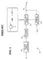
- Fig. 1shows the basic block diagram of a linear power supply 20.
- An isolation transformer 22serves two purposes. First it isolates the mains output from the system input in order to meet particular safety regulations. Second, it reduces the input voltage from a higher voltage (e.g. 110V) to a lower voltage (e.g. 5V). The reduced AC voltage is then rectified and filtered by rectifiers and filters 24 into a DC voltage.
- a series-pass element 26regulates the output DC voltage by monitoring the loading at an output 28 by feedback and control means 29.
- a disadvantage of the linear power supplyis that, due to the low AC input frequency (e.g. in the region of 60Hz), both the isolation transformer and the filter capacitors have to be relatively large. Furthermore, the power conversion efficiency of a linear power supply is only about 40 to 50%. It is also impractical to attempt to fit a linear power supply into a space which corresponds to the size of an AC mains wall outlet arrangement. Thus, due to the large size requirements, conversion from AC-to-DC voltages is typically done inside or within the device or system that requires the DC supply voltage.
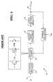
- FIG. 2shows a block diagram of a so-called “switched mode power supply” (SMPS) or “Class D” power supply 30.
- SMPSswitched mode power supply
- an AC input 32is rectified and filtered by rectifiers and filters 34 into a DC voltage without passing through an isolation transformer.
- a switching element 36(usually one or more power transistors) will chop the DC voltage into a very high frequency AC voltage (up to several hundred KHZ). This high frequency AC voltage is then fed to an isolation transformer 38 before being rectified and filtered again at rectifier and filters 40 to provide the output 42 of the power supply.
- the size of the transformer and the filter capacitorscan be relatively small.
- the switch elementsince the switch element usually dissipates very little power, the efficiency of an SMPS is usually about 70 to 80%.
- EP-A-0 409 226discloses a socket for receiving an AC input and providing a DC output which can have a selected one of a plurality of values.
- the socket and associated methodcomprise features as set out in the preambles of claims 1 and 9.
- the present inventionseeks to provide a power supply outlet exhibiting advantages over known power supply outlets.
- an electrical power supply wall outlet devicecomprising at least one connector, means for converting an AC voltage to a DC voltage, means for providing a plurality of DC voltages and for selecting a particular one of said plurality of DC voltages for said at least one connector and means for receiving an insert member insertable to assist with connection to said at least one connector, CHARACTERISED IN THAT said insert member, when inserted in said wall outlet, serves to actuate a variable resistor offering a resistance dependent upon the length of the insert member, the resistance representing the desired DC voltage.
- a method of supplying at least one DC voltage by way of a wall outlet for receiving an AC voltage and for converting said AC voltage to a DC voltage within said outlet so as to provide said DC voltage from said wall outletcomprising the step of inserting an insert member in said wall outlet to select a desired DC voltage, CHARACTERISED IN THAT the insert member is arranged to actuate a variable resistor to offer a resistance dependent upon the length of the insert member, the resistance representing the desired DC voltage.
- the present inventionis advantageous in providing for an improved power supply distribution technique and system.
- the present inventioncan also provide for an improved AC-to-DC power supply conversion arrangement which can provide an improved method for powering devices which require DC supply voltages.
- the present inventionis particularly advantageous in providing DC voltages within an electrical outlet and which can take the form of an integrated circuit device for converting AC voltages to DC voltages.
- AC-to-DC voltagescan be converted by a device attached to the normally inaccessible side of a wall outlet.
- An AC-DC voltage conversion integrated circuit (IC) of the present designcan integrate all the control and protection circuits, as well as the power transistors, into a single module. Passive components, such as the transformer and capacitors, are very small, as the switching frequency is in the KHz or MHz range. Including one or more integrated SMPS ICs in every wall outlet allows for providing a plurality of DC voltages from such outlets.
- the present inventioncan also provide for an electrical power supply outlet having at least one housing means having a first portion for access by a device requiring a supply voltage and a second portion for providing a supply voltage, wherein said first and second portions are coupled together, and an AC to DC voltage converter circuit coupled to the second portion.
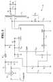
- Fig. 3shows an SMPS that can exhibit a very small form factor.
- the SMPS 50comprises an SMPS integrated circuit device 52 (hereinafter SMPS IC) and a few passive components.
- SMPS ICSMPS integrated circuit device 52
- the following design componentsprovide a 10 KHz operation at 40 Watts.
- Element 54is a full wave bridge rectifier, and preferably a Fagor silicon bridge rectifier, part number FBP04, which is available from Newark Electronics (4755 Paris Street, Denver Colorado 80239).
- Element 56is a negative temperature coefficient thermistor, preferably a Keystone NTC thermistor, stock number 81F3390, also available from Newark Electronics.
- Transformer T1is preferably a Magnetic Triad PC-Mount Flat Pack power transformer, stock number 46F1942 (for 5 volts DC output), also available from Newark Electronics.
- the remaining preferred component values for Fig. 3are shown below in Table 1.
- Fig. 4is a block diagram for the SMPS IC device 52 of Fig. 3.
- the operation of the SMPS IC device 52is known in the art, and is further described in "Power Semiconductor Devices and Circuits", by Andre A. Jaecklin, 1992, available from Plenum Press, New York.
- the physical shape of such SMPS ICis shown in Fig. 5.
- a key feature of the present inventionis that the passive components of Fig. 3 are included within a single integrated circuit device package for high switching frequency (MHz) applications.
- the integrated SMPS (iSMPS) device 50allows for inclusion of such device in a wall outlet that provides DC, or a combination of AC and/or DC, supply voltages.
- the iSMPS 50comprises the design depicted in Fig. 3.
- the component devices illustrated in Fig. 3are mounted on a printed circuit card which is contained within a rectangular case 57.
- the devicescould alternatively be mounted on a multichip module substrate.
- Three connector apertures 60are provided to accept standard AC house wiring, such as 12-2 or 14-2 AWG wires. These connector apertures 60 are similar in function to those found in standard AC outlets, where the AC wires (after having had the insulation removed from the end thereof) are press-inserted therein, and locked into place.
- a quick release element(not shown) allows for removal of the AC wires for maintenance or other purposes.
- a particularly preferred way to eliminate power dissipationis to build an on/off switch into the connection port of the outlets themselves. When someone inserts a connector into the outlet, the plug will push the switch in and turn on the iSMPS. When the plug is removed, a spring in the outlet pushes the switch back to its original position and turns off the iSMPS.
- a switch of this typeis shown in Fig. 7, with the overall system interconnectivity to such switch shown in Fig. 8.
- a microswitch 74 and springloaded actuator arm 72are mounted to a switch housing 76 to form a switch unit 70.
- the microswitch 74closes, shorting the normally open switch output to ground.
- the microswitchopens to its normally open position.
- the normally open switch outputis coupled to the iSMPS (54 of Fig. 6) via connectors 65 (DC ground) and 67 (switch output), which receives iSMPS pins 64 and 66.
- a plate 78is press-fit or otherwise physically secured (via screws or posts 75) around the outer perimeter of a block 77, and provides mounting support holes 79 for attaching an iSMPS device thereto.
- the iSMPS device 50is mounted to the upper surface of the switch unit 70 (using mounting support holes 58 of Fig. 6 and 79 of Fig. 7). Hollow spacers 82 are provided and are arranged to have screws passing therethrough. The screws provide mechanical attachment of the case 57 to the switch unit 70. The screws also provide an AC ground to switch unit 70 (from the AC ground wire 86 via device 54), in order to conform to various safety requirements.
- the other electrical connection between the iSMPS 50 and switch 70is provided by pins 62, 64 and 66, which are the DC output, DC ground, and switch output voltages, respectively, and which plug into connectors 63, 65 and 67 of Fig. 7.
- the connector 63is electrically coupled, via a copper strip (not shown) within a switch extension 81 illustrated in Fig. 7, to a conductor 88.
- a connector 65is electrically coupled, via a copper strip (not shown) within the switch extension 81 of Fig. 7, to a conductor 90.
- the wall outlet 80can provide DC voltages to the conductors 88 and 90.
- a face plate 92is attached to the switch 70 of the wall outlet 80 by two screws 94, as shown in Fig. 9.
- the preferred order for initial construction of the assembly shown in Fig. 9is to attach the switch 70 to the stud of a wall via the switch housing mounting holes (83 of Fig. 7), in a manner similar known techniques when mounting electrical boxes to studs.
- the iSMPS device 50is then mounted on top of the switch 70.
- the wires 84, 86 and 88, which provide AC input voltages,are then connected to the iSMPS 50.
- the face plate 92is attached to switch 70.
- the entire wall outlet 80can be pre-assembled into a single mounting box, and this box can be then mechanically attached to a support structure (such as a stud), and electrically attached to an AC supply voltage.
- an electrical jack 96is inserted into the wall outlet 80 through the face plate 92.
- the jack 96has two indented regions 98 and 100.
- the conductors 88 and 90are received, and preferably lock, into respective indented regions 100 and 98 of the jack 96. This locking provides for both a mechanical support, to hold the jack in the outlet, and an electrical connection between the conductors 88/90 and the jack 96.
- the tip 102 of the jack 96will depress the switch actuator 72.
- the switch output signal on the conductor 66will short to ground, indicating that DC supply voltages should be supplied via the connecting posts 62 and 64 to the conductors 88 and 90.
- a jack when fully engaged in a wall outletis shown in Fig. 10.
- DC output voltage levelAnother problem that arises with a mere DC outlet is the DC output voltage level. Different devices may require different voltage levels, and using a wrong voltage level may damage the device(s) and create safety hazards.
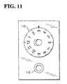
- a rotary control knob 110By turning a rotary control knob 110, a user can choose the voltage level within the output range.
- the output voltageis regulated by comparing the output voltage with a reference voltage. Therefore, by changing the reference voltage (through turning the knob 110), the output voltage level provided at the connector 112 can be readily adjusted.
- an adjustable outletcan give users the freedom of choosing the voltage level required, in many cases a user may either forget to adjust the outlet or simply will not know the correct voltage level for the device(s) they want to use.
- the inventionprovides DC outlets with a selection of fixed, and commonly used, standard voltage levels.
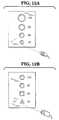
- the size, or shape, of the outletscan be arranged as a function of the voltage level, as shown in Figs. 12A-12B.
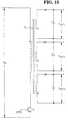
- a single SMPScan generate several different output voltages at the same time by having several different secondary windings in the isolation transformer.
- Fig. 13shows how this can be implemented in the iSMPS.
- Switch 70(Figs. 7-10) can also be modified to provide additional electrical interconnections, in a similar fashion to that as shown with reference to the pins 62,64,66, the connectors 63,65,76, and the conductors 88,90 to accommodate the additional voltages.
- an incremental multi-position switch, or linear switchwhich basically comprises a variable resistor whose resistance depends on how far it has been pushed in. Plugs with different lengths for different voltage levels are advantageously employed. As shown in Fig. 14, a 6V plug pushes the switch further into the outlets than the 3V plug. As a result, the resistance of the switch sets the output voltage to 6V. By doing so, the output voltage of the outlet can be set automatically by the device without manual adjustment.
- the wall outlet of Fig. 8can be modified by replacing the on-off micro-switch 72 with such a linear switch.
- the output resistance presented on the switch output pin 66now represents the desired DC voltage. This output resistance is used in a voltage divider, using standard techniques known in the art, to divide down, or reduce, a maximum possible DC voltage to the desired value.
- each DC outletprovides a different voltage level, using the voltage selection techniques previously described.
- the previously described linear switch (Fig. 14) or adjustment knob (Fig. 11)can be provided in relation to the DC outlets.
- the adjustment knob(s)each of the four outlets can be adjusted independently but four iSMPS devices, or a device to disable other ports when one port is in use (as further described below) are required.
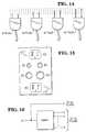
- the iSMPS input AC voltageis provided directly to the AC plugs, as in Fig. 16.
- Fig. 17illustrates the mechanical structure for such a combined AC/DC voltage supply source, and further exemplifies the flexibility of this modular approach.
- the upper portion of the outlet 120comprises a traditional AC outlet 114, having a mounting structure 118.
- the lower portion 116provides the DC voltages for the upper portion (i.e. the 3 volt and 6 volt) of the outlet shown in Fig. 15.
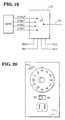
- Fig. 18shows a front view of wall outlet 120.
- the lower portion 116has a cover plate 117 similar to element 92 of Figs. 9 and 10.
- a similar device to that shown in Figs. 17 and 18is used to provide the AC and DC voltages for the lower portion (i.e. the 9 volt and 12 volt) of the outlet shown in Fig. 15.
- a DC wall outlet 116has been modified from that shown at 80 in Fig. 8 to include AC connector pins 122 on the upper surface of the iSMPS device 124. These AC connector pins plug into receptacles 126 on the lower surface of AC outlet 114, in order to directly supply AC voltage to such AC outlet.
- the device 116is mechanically attached to AC outlet 114 by one or more screws 128.
- Fig. 19shows how to disable all but one port when a single iSMPS device is used with a plurality of DC outlets.
- the iSMPS deviceprovides four DC output voltages, using techniques as previously described with respect to Fig. 13. These DC voltages are coupled to a multiplexer or cross-bar 122.
- the multiplexerselectively couples one of the input voltages (3, 6, 9 and 12 volts) to its output terminal 124, based upon the select values SEL0-SEL3. These select values are either +5 volts or ground, depending on whether a jack is plugged into a respective input terminal. If more than one jack is plugged in (i.e. its select line tied to ground), the multiplexer provides the highest voltage requested.
- a truth table for the multiplexer 122is shown below in Table 2.
- SEL0 SEL1 SEL2 SEL33V 6V 9V 12V 0 0 0 0 NO NO NO YES 0 0 0 1 NO NO YES NO 0 0 1 0 NO NO NO YES 0 0 1 1 NO YES NO NO 0 1 0 0 NO NO NO YES NO 0 1 1 0 NO NO NO YES NO 0 1 1 1 0 NO NO NO YES 0 1 1 1 0 NO NO NO YES 0 1 1 1 YES NO NO NO 1 0 0 0 NO NO NO YES 1 0 0 1 NO NO NO YES NO 1 0 1 0 NO NO NO YES NO 1 0 1 0 NO NO NO YES NO 1 0 1 0 NO NO NO YES NO 1 0 1 0 NO NO NO YES NO 1 0 1 0 NO NO NO YES NO 1 0 1 0 NO NO NO
- a logical ZERO (0 volts)means a jack is plugged into the respective plug, whereas a logical ONE (+5 volts) means no jack is plugged into the respective plug.
- a 'yes' in the output columnmeans the corresponding multiplexer/selector's input voltage is coupled to the output 124.
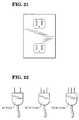
- each outlethas three slots instead of two.
- a default setting for the outletis that an AC output is provided.
- the extra legwill turn on the SMPS and switch the outlet to the DC mode.
- the length of the legdetermines the DC output voltage level automatically, as previously described. If an AC plug having a third ground leg needs to be accommodated, then a fourth slot is added to the outlet of Fig. 21. This fourth slot would receive the extra DC leg just described.
Landscapes
- Engineering & Computer Science (AREA)
- Power Engineering (AREA)
- Microelectronics & Electronic Packaging (AREA)
- Rectifiers (AREA)
- Dc-Dc Converters (AREA)
- Details Of Connecting Devices For Male And Female Coupling (AREA)
Description
- The present invention relates to a power supplyoutlet.
- In many electronic appliances and devices (e.g.electronic clocks, radios, CD players, computers, videogames, etc.), the bulkiest part or component is the powersupply arrangement which, traditionally, requires a largeand heavy isolation transformer and, sometimes, a heat sinkand a cooling fan. The power supply arrangement serves toconvert the AC voltage from the mains outlet to a DCvoltage that can be used by the system. For some systemsthat do not have a built-in power supply arrangement (e.g.portable computers), an external AC-to-DC adapter is neededto operate the systems from a mains outlet.
- The reason for providing AC voltages by way of typicalpower outlets, such as a wall outlet, is that the onlycost-effective way to convert an AC voltage to a DC voltageis by means of a linear power supply. Fig. 1 shows thebasic block diagram of a
linear power supply 20. Anisolation transformer 22 serves two purposes. First itisolates the mains output from the system input in order tomeet particular safety regulations. Second, it reduces theinput voltage from a higher voltage (e.g. 110V) to a lowervoltage (e.g. 5V). The reduced AC voltage is thenrectified and filtered by rectifiers and filters 24 into aDC voltage. A series-pass element 26 regulates the outputDC voltage by monitoring the loading at anoutput 28 byfeedback and control means 29. A disadvantage of thelinear power supply is that, due to the low AC inputfrequency (e.g. in the region of 60Hz), both the isolationtransformer and the filter capacitors have to be relativelylarge. Furthermore, the power conversion efficiency of alinear power supply is only about 40 to 50%. It is also impractical to attempt to fit a linear power supply into a space which corresponds to thesize of an AC mains wall outlet arrangement. Thus, due to the large size requirements,conversion from AC-to-DC voltages is typically done inside or within the device or systemthat requires the DC supply voltage. - The progress of power semiconductor technology in recent years has made a newtype of power supply potentially economically viable. Fig. 2 shows a block diagram of aso-called "switched mode power supply" (SMPS) or "Class D"
power supply 30. In anSMPS, anAC input 32 is rectified and filtered by rectifiers and filters 34 into a DCvoltage without passing through an isolation transformer. A switching element 36 (usuallyone or more power transistors) will chop the DC voltage into a very high frequency ACvoltage (up to several hundred KHZ). This high frequency AC voltage is then fed to anisolation transformer 38 before being rectified and filtered again at rectifier andfilters 40to provide theoutput 42 of the power supply. Since the transformer and the output filteronly have to deal with a very high frequency AC voltage, the size of the transformer andthe filter capacitors can be relatively small. In addition, since the switch element usuallydissipates very little power, the efficiency of an SMPS is usually about 70 to 80%. - However, the advent of SMPS has disadvantageously only resulted in reducing thesize, weight, and cost of power supply arrangements provided inside, or within, the devicerequiring the DC supply voltage.
- EP-A-0 409 226 discloses a socket for receiving an AC input and providing a DCoutput which can have a selected one of a plurality of values. The socket andassociated method comprise features as set out inthe preambles of
claims - The present invention seeks to provide a power supply outlet exhibiting advantagesover known power supply outlets.
- In accordance with one aspect of the present invention, there is provided anelectrical power supply wall outlet device comprising at least one connector, means forconverting an AC voltage to a DC voltage, means for providing a plurality of DC voltages and for selecting a particular one of said plurality of DC voltages for said at least oneconnector and means for receiving an insert member insertable to assistwith connection to said at least one connector, CHARACTERISED IN THAT said insert member, when insertedin said wall outlet, serves to actuate a variable resistor offering a resistance dependent uponthe length of the insert member, the resistance representing thedesired DC voltage.
- In accordance with another aspect of the present invention, there is provided amethod of supplying at least one DC voltage by way of a wall outlet for receiving an ACvoltage and for converting said AC voltage to a DC voltage within said outlet so as toprovide said DC voltage from said wall outlet, comprising the step of inserting aninsert member in said wall outlet to select a desired DC voltage, CHARACTERISED IN THAT the insert member is arranged to actuate a variable resistor to offera resistance dependent upon the length of the insert member, the resistancerepresenting the desired DC voltage.
- The present invention is advantageous in providing for an improved power supplydistribution technique and system.
- The present invention can also provide for an improved AC-to-DC power supplyconversion arrangement which can provide an improved method for powering deviceswhich require DC supply voltages.
- Further, the present invention is particularly advantageous in providing DCvoltages within an electrical outlet and which can take the form of an integrated circuitdevice for converting AC voltages to DC voltages.
- As will be appreciated, it is a particular preferred feature of the present inventionthat AC-to-DC voltages can be converted by a device attached to the normally inaccessibleside of a wall outlet.
- An AC-DC voltage conversion integrated circuit (IC) of the present design canintegrate all the control and protection circuits, as well as the power transistors, into asingle module. Passive components, such as the transformer and capacitors, are very small, as theswitching frequency is in the KHz or MHz range. Includingone or more integrated SMPS ICs in every wall outlet allowsfor providing a plurality of DC voltages from such outlets.
- The present invention can also provide for anelectrical power supply outlet having at least one housingmeans having a first portion for access by a devicerequiring a supply voltage and a second portion forproviding a supply voltage, wherein said first and secondportions are coupled together, and an AC to DC voltageconverter circuit coupled to the second portion.
- The invention is described further hereinafter, by wayof example only, with reference to the accompanyingdrawings in which:
- Fig. 3 is a schematic illustration of a switch modepower supply;
- Fig. 4 is a block diagram of a partially integratedswitched mode power supply (SMPS) integrated circuitdevice;
- Fig. 5 illustrates the physical structure for thepartially integrated SMPS integrated circuit device ofFig.4;
- Fig. 6 illustrates the physical structure of a fullyintegrated SMPS;
- Fig. 7 illustrates a switch for turning off anintegrated SMPS;
- Fig. 8 illustrates an integrated SMPS and switch foruse as a power supply wall outlet;
- Fig. 9 illustrates a power supply wall outlet with aninterconnecting electrical jack;
- Fig. 10 illustrates a wall outlet with an engagedinterconnecting electrical jack;
- Fig. 11 illustrates a DC voltage selection technique using a knob;
- Figs. 12A-12B illustrate a DC voltage selectiontechnique using different sizes and shapes of connectorsand plugs;
- Fig. 13 illustrates the generation of a plurality ofDC voltages from an integrated SMPS;
- Fig. 14 illustrates a technique for automaticallyselecting a DC voltage from a common receptacle;
- Fig. 15 illustrates a combined AC and DC wall outlet;
- Fig. 16 illustrates the internal wiring for supplyingthe combined outlet of Fig. 15 with both AC and DCvoltages;
- Fig. 17 illustrates a side view of a combined AC/DCoutlet;
- Fig. 18 illustrates a front view of a combined AC/DCoutlet;
- Fig. 19 illustrates a multiplexer/selector forcoupling a specified DC voltage to a receptacle;
- Fig. 20 illustrates a wall outlet with a commonreceptacle providing both AC and DC voltages;
- Fig. 21 illustrates an alternative wall outlet with acommon receptacle for providing both AC and DC voltages;and
- Fig. 22 illustrates a plurality of plugs havingdifferent pin configurations for selecting which type ofvoltage (AC or DC) is provided by the receptacle ofFig. 21.
- Fig. 3 shows an SMPS that can exhibit a very smallform factor. The SMPS 50 comprises an SMPS integratedcircuit device 52 (hereinafter SMPS IC) and a few passivecomponents. The following design components provide a 10KHz operation at 40 Watts. Element 54 is a full wavebridge rectifier, and preferably a Fagor silicon bridgerectifier, part number FBP04, which is available fromNewark Electronics (4755 Paris Street, Denver Colorado 80239).
Element 56 is a negative temperature coefficientthermistor, preferably a Keystone NTC thermistor, stocknumber 81F3390, also available from Newark Electronics.Transformer T1 is preferably a Magnetic Triad PC-Mount FlatPack power transformer, stock number 46F1942 (for 5 voltsDC output), also available from Newark Electronics. Theremaining preferred component values for Fig. 3 are shownbelow in Table 1.DEVICE VALUE R1 5 ohms R2 100K ohms R3 40 K ohms R4 60 K ohms R5 10 K ohms R6 1 M ohms C1 60 uF C2 60 uF C3 10 uF C4 10 uF C5 1 uF C6 100 uF C7 100 uF D1 400 V, 10A D2 400 V, 10A D3 400 V, 10A - Fig. 4 is a block diagram for the
SMPS IC device 52 ofFig. 3. The operation of theSMPS IC device 52 is known inthe art, and is further described in "Power SemiconductorDevices and Circuits", by Andre A. Jaecklin, 1992,available from Plenum Press, New York. The physical shape of such SMPS IC is shown in Fig. 5. - A key feature of the present invention is that thepassive components of Fig. 3 are included within a singleintegrated circuit device package for high switchingfrequency (MHz) applications. As shown in Fig. 6, theintegrated SMPS (iSMPS)
device 50 allows for inclusion ofsuch device in a wall outlet that provides DC, or acombination of AC and/or DC, supply voltages. - Referring now in detail to Fig. 6, the
iSMPS 50comprises the design depicted in Fig. 3. The componentdevices illustrated in Fig. 3 are mounted on a printedcircuit card which is contained within arectangular case 57. The devices could alternatively be mounted on a multichipmodule substrate. There are four mountingholes 58used to attach thecase 56 to a switch housing (later shownin Figs. 7 and 8). Threeconnector apertures 60 areprovided to accept standard AC house wiring, such as 12-2or 14-2 AWG wires. Theseconnector apertures 60 aresimilar in function to those found in standard AC outlets,where the AC wires (after having had the insulation removedfrom the end thereof) are press-inserted therein, andlocked into place. A quick release element (not shown)allows for removal of the AC wires for maintenance or otherpurposes. Threeconductive posts case 56, are provided for electricalconnection to the switch illustrated with reference Fig. 8. - The above embodiments, techniques and arrangementsallow for the design and implementation of DC-only orcombined selective AC/DC wall outlets which can be the samesize as currently available AC outlets. However, severaldifferences are exhibited with the DC outlets with regardto the AC outlets. First of all, the AC outlets do not consume any power. The iSMPS IC will dissipate power evenwhen the output is not loaded. It is desirable thereforeto turn off the iSMPS when nothing is inserted in the walloutlet or socket. A particularly effective and simple wayis to have an on/off switch associated with the outlet. Auser can then turn off the iSMPS when power is not requiredfrom the outlets. A further feature is that the outletscan automatically turn off when not used. A particularlypreferred way to eliminate power dissipation is to build anon/off switch into the connection port of the outletsthemselves. When someone inserts a connector into theoutlet, the plug will push the switch in and turn on theiSMPS. When the plug is removed, a spring in the outletpushes the switch back to its original position and turnsoff the iSMPS. A switch of this type is shown in Fig. 7,with the overall system interconnectivity to such switchshown in Fig. 8.
- Referring now to Fig. 7, a
microswitch 74 andspringloadedactuator arm 72 are mounted to aswitch housing 76to form aswitch unit 70. When theactuator arm 72 isdepressed, themicroswitch 74 closes, shorting the normallyopen switch output to ground. When the actuator arm isreleased, the microswitch opens to its normally openposition. The normally open switch output is coupled tothe iSMPS (54 of Fig. 6) via connectors 65 (DC ground) and67 (switch output), which receives iSMPS pins 64 and 66. Aplate 78 is press-fit or otherwise physically secured (viascrews or posts 75) around the outer perimeter of ablock 77, and provides mounting support holes 79 for attaching aniSMPS device thereto. - As shown in Fig. 8, the
iSMPS device 50 is mounted tothe upper surface of the switch unit 70 (using mountingsupport holes 58 of Fig. 6 and 79 of Fig. 7).Hollowspacers 82 are provided and are arranged to have screws passing therethrough. The screws provide mechanicalattachment of thecase 57 to theswitch unit 70. Thescrews also provide an AC ground to switch unit 70 (fromtheAC ground wire 86 via device 54), in order to conformto various safety requirements. The other electricalconnection between theiSMPS 50 andswitch 70 is providedbypins switch extension 81 illustrated in Fig. 7, to aconductor 88. A connector 65 is electrically coupled, viaa copper strip (not shown) within theswitch extension 81of Fig. 7, to aconductor 90. Thus, thewall outlet 80 canprovide DC voltages to theconductors - A
face plate 92 is attached to theswitch 70 of thewall outlet 80 by twoscrews 94, as shown in Fig. 9. Thepreferred order for initial construction of the assemblyshown in Fig. 9 is to attach theswitch 70 to the stud of awall via the switch housing mounting holes (83 of Fig. 7),in a manner similar known techniques when mountingelectrical boxes to studs. TheiSMPS device 50 is thenmounted on top of theswitch 70. Thewires iSMPS 50. After drywalling, or other exterior surfacingfor the wall has been completed, theface plate 92 isattached to switch 70. Alternatively, theentire walloutlet 80 can be pre-assembled into a single mounting box,and this box can be then mechanically attached to asupport structure (such as a stud), and electricallyattached to an AC supply voltage. - In operation, an
electrical jack 96 is inserted intothewall outlet 80 through theface plate 92. Thejack 96has twoindented regions conductors indentedregions jack 96. This locking providesfor both a mechanical support, to hold the jack in theoutlet, and an electrical connection between theconductors 88/90 and thejack 96. Also, upon insertion, thetip 102of thejack 96 will depress theswitch actuator 72. Theswitch output signal on theconductor 66 will short toground, indicating that DC supply voltages should besupplied via the connectingposts conductors - Another problem that arises with a mere DC outlet isthe DC output voltage level. Different devices may requiredifferent voltage levels, and using a wrong voltage levelmay damage the device(s) and create safety hazards.
- Such aproblem can be overcome by including an adjustable output, as shown in Fig.11. By turning a
rotary control knob 110, a user canchoose the voltage level within the output range. In theiSMPS, the output voltage is regulated by comparing theoutput voltage with a reference voltage. Therefore, bychanging the reference voltage (through turning the knob110), the output voltage level provided at theconnector 112 can be readily adjusted. - Although an adjustable outlet can give users thefreedom of choosing the voltage level required, in manycases a user may either forget to adjust the outlet orsimply will not know the correct voltage level for thedevice(s) they want to use. In view of this the inventionprovides DC outlets with a selection of fixed, andcommonly used, standard voltage levels. To seek to ensurethat users use the appropriate voltage level, in a manner not in accordance with the invention, the size, orshape, of the outlets can be arranged as a function of the voltage level, as shown in Figs. 12A-12B. It should benoted that a single SMPS can generate several differentoutput voltages at the same time by having severaldifferent secondary windings in the isolation transformer.Fig. 13 shows how this can be implemented in the iSMPS.Switch 70 (Figs. 7-10) can also be modified to provideadditional electrical interconnections, in a similarfashion to that as shown with reference to the
pins connectors 63,65,76, and theconductors - Alternatively, in accordance with the invention, the same concept of having a built-inswitch in the port of the outlets can be applied. However,instead of having an on/off switch, there can be providedan incremental multi-position switch, or linear switch,which basically comprises a variable resistor whoseresistance depends on how far it has been pushed in. Plugswith different lengths for different voltage levels areadvantageously employed. As shown in Fig. 14, a 6V plugpushes the switch further into the outlets than the 3Vplug. As a result, the resistance of the switch sets theoutput voltage to 6V. By doing so, the output voltage ofthe outlet can be set automatically by the device withoutmanual adjustment. The wall outlet of Fig. 8 can bemodified by replacing the on-off
micro-switch 72 with sucha linear switch. The output resistance presented on theswitch output pin 66 now represents the desired DC voltage.This output resistance is used in a voltage divider, usingstandard techniques known in the art, to divide down, orreduce, a maximum possible DC voltage to the desired value. - In some instances, it will prove advantageous to beable to obtain both AC and DC output voltages from the samewall outlet unit. To accommodate this, the AC outlets canbe combined with the DC outlets. Fig. 15 shows a unit withtwo AC outlets and four DC outlets. In a manner not in accordance with the invention, each DC outlet provides a different voltage level, using the voltageselection techniques previously described. Alternatively,the previously described linear switch (Fig. 14) oradjustment knob (Fig. 11) can be provided in relation tothe DC outlets. For the adjustment knob(s), each of thefour outlets can be adjusted independently but four iSMPSdevices, or a device to disable other ports when one portis in use (as further described below) are required. TheiSMPS input AC voltage is provided directly to the ACplugs, as in Fig. 16.
- Fig. 17 illustrates the mechanical structure for sucha combined AC/DC voltage supply source, and furtherexemplifies the flexibility of this modular approach. Theupper portion of the
outlet 120 comprises atraditional ACoutlet 114, having a mountingstructure 118. Thelowerportion 116 provides the DC voltages for the upper portion(i.e. the 3 volt and 6 volt) of the outlet shown in Fig.15. Fig. 18 shows a front view ofwall outlet 120. Thelower portion 116 has acover plate 117 similar toelement 92 of Figs. 9 and 10. A similar device to that shown inFigs. 17 and 18 is used to provide the AC and DC voltagesfor the lower portion (i.e. the 9 volt and 12 volt) of theoutlet shown in Fig. 15. - Continuing with Fig. 17, a
DC wall outlet 116 has beenmodified from that shown at 80 in Fig. 8 to include ACconnector pins 122 on the upper surface of theiSMPS device 124. These AC connector pins plug intoreceptacles 126 onthe lower surface ofAC outlet 114, in order to directlysupply AC voltage to such AC outlet. Thedevice 116 ismechanically attached toAC outlet 114 by one ormorescrews 128. - Fig. 19 shows how to disable all but one port when asingle iSMPS device is used with a plurality of DC outlets. The iSMPS device provides four DC output voltages, usingtechniques as previously described with respect to Fig. 13.These DC voltages are coupled to a multiplexer or cross-bar122. The multiplexer selectively couples one of the inputvoltages (3, 6, 9 and 12 volts) to its
output terminal 124,based upon the select values SEL0-SEL3. These selectvalues are either +5 volts or ground, depending on whethera jack is plugged into a respective input terminal. Ifmore than one jack is plugged in (i.e. its select line tiedto ground), the multiplexer provides the highest voltagerequested. A truth table for themultiplexer 122 is shownbelow in Table 2.SEL0 SEL1 SEL2 SEL3 3V 6V 9V 12V 0 0 0 0 NO NO NO YES 0 0 0 1 NO NO YES NO 0 0 1 0 NO NO NO YES 0 0 1 1 NO YES NO NO 0 1 0 0 NO NO NO YES 0 1 0 1 NO NO YES NO 0 1 1 0 NO NO NO YES 0 1 1 1 YES NO NO NO 1 0 0 0 NO NO NO YES 1 0 0 1 NO NO YES NO 1 0 1 0 NO NO NO YES 1 0 1 1 NO YES NO NO 1 1 0 0 NO NO NO YES 1 1 0 1 NO NO YES NO 1 1 1 0 NO NO NO YES 1 1 1 1 NO NO NO NO Selectline 1 corresponds to the 6 volt plug, Select Line 2 (SEL2)corresponds to the 9 volt plug, and Select Line 3 (SEL3)corresponds to the 12 volt plug. A logical ZERO (0 volts)means a jack is plugged into the respective plug, whereas alogical ONE (+5 volts) means no jack is plugged into therespective plug. A 'yes' in the output column means thecorresponding multiplexer/selector's input voltage iscoupled to theoutput 124. - It is also possible that users may want to use thesame port for either AC or DC output. A simple solution isto have a switch which can choose between AC and DC outputand a knob to adjust the voltage level if DC is chosen, asshown in Fig. 20. However, a safer and more elegantsolution is to use a slightly different plug for DCapplications. As shown in Fig. 21, each outlet has threeslots instead of two. A default setting for the outlet isthat an AC output is provided. When a DC plug with anextra leg is plugged into the outlet, as shown in Fig. 22,the extra leg will turn on the SMPS and switch the outletto the DC mode. In accordance with the invention, the length of the leg determines the DCoutput voltage level automatically, as previouslydescribed. If an AC plug having a third ground leg needsto be accommodated, then a fourth slot is added to theoutlet of Fig. 21. This fourth slot would receive theextra DC leg just described.
- While embodiments of the invention have beenillustrated and described above, it is to be understoodthat the invention is not restricted to the detail of theforegoing embodiments.
Claims (10)
- An electrical power supply wall outlet device (50) comprising at least oneconnector (62, 64, 66), means (52, 54) for converting an AC voltage to a DC voltage.means for providing a plurality of DC voltages and for selecting a particular one of saidplurality of DC voltages for said at least one connector (62, 64, 66) andmeans for receiving an insert member insertable to assist with connection to said at leastone connector (62, 64, 66),CHARACTERISED IN THAT said insert member, when inserted in said wall outlet,serves to actuate a variable resistor offering a resistance dependent upon the length of theinsert member, the resistance representing the desired DCvoltage.
- A device as claimed in Claim 1, and including enabling means for controllingoperation of said means for converting said AC voltage to said DC voltage.
- A device as claimed in Claim 2, wherein said enabling means comprises switchmeans arranged to be operated by insertion of an insert member (96) into said device toassist with the connection to said connector.
- A device as claimed in any one of the preceding claims, and further comprising atleast one AC connector for providing an AC voltage output.
- A device as claimed in Claim 4, further comprising selection means for selectivelycoupling either said AC voltage or said DC voltage to said at least one connector (62, 64,66).
- A device as claimed in Claim 5, wherein said selection means is arranged to beoperated by insert means associated with an electrical connector to be received by saidoutlet.
- A device as claimed in any one of the preceding claims, wherein said means forconverting said AC voltage comprises a single module.
- A device as claimed in Claim 7, wherein said module integrates all control andprotection circuits and power transistors and includes a plurality of integrated switchedmode power supply devices for providing at least one of a plurality of DC voltages.
- A method of supplying at least one DC voltage by way of a wall outlet forreceiving an AC voltage and for converting said AC voltage to a DC voltage within saidoutlet so as to provide said DC voltage from said wall outlet, comprising the step ofinserting an insert member in said wall outlet to select a desired DC voltage,CHARACTERISED IN THAT the insert member is arranged to actuate a variableresistor to offer a resistance dependent upon the length of the insert member, theresistance representing the desired DC voltage.
- A method as claimed in Claim 9, wherein said AC voltage is converted by way ofa single module comprising an integrated circuit device,
Applications Claiming Priority (2)
| Application Number | Priority Date | Filing Date | Title |
|---|---|---|---|
| US337591 | 1989-04-12 | ||
| US08/337,591US5563782A (en) | 1994-11-10 | 1994-11-10 | Wall outlet with direct current output |
Publications (3)
| Publication Number | Publication Date |
|---|---|
| EP0712200A2 EP0712200A2 (en) | 1996-05-15 |
| EP0712200A3 EP0712200A3 (en) | 1996-09-25 |
| EP0712200B1true EP0712200B1 (en) | 2001-10-24 |
Family
ID=23321160
Family Applications (1)
| Application Number | Title | Priority Date | Filing Date |
|---|---|---|---|
| EP95308075AExpired - LifetimeEP0712200B1 (en) | 1994-11-10 | 1995-11-10 | Power supply outlet |
Country Status (5)
| Country | Link |
|---|---|
| US (2) | US5563782A (en) |
| EP (1) | EP0712200B1 (en) |
| JP (1) | JP3547243B2 (en) |
| KR (1) | KR100378936B1 (en) |
| DE (1) | DE69523410T2 (en) |
Families Citing this family (88)
| Publication number | Priority date | Publication date | Assignee | Title |
|---|---|---|---|---|
| US6266261B1 (en)* | 1994-04-26 | 2001-07-24 | Comarco Wireless Technologies, Inc. | DC power adapter system |
| US5563782A (en)* | 1994-11-10 | 1996-10-08 | At&T Global Information Solutions Company | Wall outlet with direct current output |
| US5777397A (en)* | 1996-10-23 | 1998-07-07 | Lam; Phillip | Host electronic equipment with internal power supply adapted for supplying power to peripherals |
| US5753979A (en)* | 1996-10-23 | 1998-05-19 | Am Group Corporation | Host electronic equipment with internal power supply adapted for supplying power directly to peripherals |
| US5757638A (en)* | 1996-12-31 | 1998-05-26 | Sansha Electric Manufacturing Company, Limited | Power supply apparatus |
| US5777868A (en)* | 1997-04-24 | 1998-07-07 | Ventur Research & Development Inc | Electrical Plug |
| US6049142A (en)* | 1997-12-22 | 2000-04-11 | Ericsson Inc. | Voltage adapting system and method using modular adapter plugs |
| US5900684A (en)* | 1998-04-14 | 1999-05-04 | Am Group, Corporation | Power supply system for failsafe supply of different DC voltages |
| US6480510B1 (en) | 1998-07-28 | 2002-11-12 | Serconet Ltd. | Local area network of serial intelligent cells |
| US5946180A (en)* | 1998-08-26 | 1999-08-31 | Ofi Inc. | Electrical connection safety apparatus and method |
| TW450462U (en)* | 1999-01-29 | 2001-08-11 | Delta Electronics Inc | Power supply adapter |
| US6160728A (en)* | 1999-05-26 | 2000-12-12 | Advanced Micro Devices, Inc. | Dual-mode AC/DC electrical receptacle |
| US6956826B1 (en) | 1999-07-07 | 2005-10-18 | Serconet Ltd. | Local area network for distributing data communication, sensing and control signals |
| US6690677B1 (en) | 1999-07-20 | 2004-02-10 | Serconet Ltd. | Network for telephony and data communication |
| WO2001043266A1 (en)* | 1999-12-10 | 2001-06-14 | Am Group Corp. | Electrical power strip with ac to dc power supply |
| US6502730B2 (en) | 2000-01-06 | 2003-01-07 | Danny R. Johnson | Carrier rack for vehicle |
| IL135744A (en) | 2000-04-18 | 2008-08-07 | Mosaid Technologies Inc | Telephone communication system over a single telephone line |
| DE10020074C5 (en)* | 2000-04-22 | 2010-04-29 | Pilz Gmbh & Co. Kg | Modular safety relay system |
| US7733069B2 (en)* | 2000-09-29 | 2010-06-08 | Canon Kabushiki Kaisha | Power converting apparatus and power generating apparatus |
| US6362987B1 (en)* | 2000-12-27 | 2002-03-26 | John Yurek | Wall mounted electrical outlet receptacle for providing low voltage DC current |
| IL144158A (en) | 2001-07-05 | 2011-06-30 | Mosaid Technologies Inc | Outlet for connecting an analog telephone set to a digital data network carrying voice signals in digital form |
| US6781249B2 (en)* | 2001-08-29 | 2004-08-24 | Hewlett-Packard Development Company, L.P. | Retrofittable power supply |
| EP2234394A1 (en) | 2001-10-11 | 2010-09-29 | Mosaid Technologies Incorporated | Coupling device |
| AT5418U1 (en) | 2001-10-11 | 2002-06-25 | Geyer Imp Exp Ges M B H | DISTRIBUTOR WITH SEVERAL SOCKETS |
| US6737909B2 (en)* | 2001-11-26 | 2004-05-18 | Intel Corporation | Integrated circuit current reference |
| US7212420B2 (en)* | 2002-02-12 | 2007-05-01 | Sheng Hsin Liao | Universal serial bus voltage transformer |
| US6628535B1 (en)* | 2002-03-20 | 2003-09-30 | Formosa Electronic Industries Inc. | Voltage converter with selectable DC output voltage level |
| US6672890B1 (en)* | 2002-05-28 | 2004-01-06 | Heath P. Witherspoon | Electrical adapter |
| US20040053535A1 (en)* | 2002-09-16 | 2004-03-18 | Liu Shao Gong | Multi-function socket combination |
| IL152824A (en) | 2002-11-13 | 2012-05-31 | Mosaid Technologies Inc | Addressable outlet and a network using same |
| US7140922B2 (en)* | 2002-12-19 | 2006-11-28 | Pacusma Company, Ltd. | Multi-outlet AC/DC adapter |
| US7724557B2 (en)* | 2003-01-09 | 2010-05-25 | Pass & Seymour, Inc. | Electrical wiring device with a center nightlight having automatic and manual control features |
| US6875059B2 (en)* | 2003-01-15 | 2005-04-05 | American Megatrends, Inc. | In-line remote controllable power switch with integrated power supply |
| US6841975B2 (en)* | 2003-05-06 | 2005-01-11 | Albert Cho | Voltage regulator having insert slots |
| US7610119B2 (en)* | 2003-07-08 | 2009-10-27 | Omron Corporation | Safety controller and system using same |
| IL157787A (en) | 2003-09-07 | 2010-12-30 | Mosaid Technologies Inc | Modular outlet for data communications network |
| DE10335866A1 (en)* | 2003-08-06 | 2005-03-03 | Volkswagen Ag | Kraftfahrzeugumrichter |
| US7416310B1 (en)* | 2003-12-02 | 2008-08-26 | Pass & Seymour, Inc. | Power control device for an electrical load |
| IL159838A0 (en) | 2004-01-13 | 2004-06-20 | Yehuda Binder | Information device |
| IL160417A (en) | 2004-02-16 | 2011-04-28 | Mosaid Technologies Inc | Outlet add-on module |
| DE102004018780A1 (en)* | 2004-04-15 | 2005-06-16 | Siemens Ag | House current supply for low power appliances with low voltage (LV), with at least one LV socket, especially in plug socket designed for inserting and mechanical holding correspondingly shaped plug section |
| US7682656B2 (en)* | 2004-06-14 | 2010-03-23 | Agruim Inc. | Process and apparatus for producing a coated product |
| US20060043796A1 (en)* | 2004-09-02 | 2006-03-02 | Biskup James H Sr | AC wall receptacle with integral DC power supply |
| US7873058B2 (en) | 2004-11-08 | 2011-01-18 | Mosaid Technologies Incorporated | Outlet with analog signal adapter, a method for use thereof and a network using said outlet |
| CN101068628B (en)* | 2004-11-30 | 2012-04-25 | 爱禾瑞公司 | Method and apparatus for coating a controlled release product in a rotating drum |
| US7257466B2 (en)* | 2004-12-02 | 2007-08-14 | At&T Intellectual Property, Inc. | Intelligent control devices |
| DE102005010866A1 (en) | 2005-03-07 | 2006-09-14 | Sennheiser Electronic Gmbh & Co. Kg | Plug-in socket with voltage transformer |
| US7466042B2 (en)* | 2005-04-06 | 2008-12-16 | Flexsil, Inc. | Universal DC power |
| US20070029879A1 (en)* | 2005-08-04 | 2007-02-08 | Eldredge James G | Distribution of universal DC power in buildings |
| US20070040448A1 (en)* | 2005-08-16 | 2007-02-22 | Tsung-I Yu | Extension cable with ac power sockets and dc power sockets |
| US20070091656A1 (en)* | 2005-10-13 | 2007-04-26 | Amir Navid | Power adapter |
| US7642671B2 (en)* | 2006-04-28 | 2010-01-05 | Acco Brands Usa Llc | Power supply system providing two output voltages |
| US8143848B2 (en) | 2006-10-13 | 2012-03-27 | Nyko Technologies, Inc. | Video game controller charging system having a docking structure |
| US8134254B2 (en)* | 2006-11-09 | 2012-03-13 | The Wiremold Company | DC power outlets in fixed power distribution systems in or on wall installations |
| US7782642B2 (en)* | 2006-12-05 | 2010-08-24 | Sony Corporation | Power brick with passthrough |
| US7745954B1 (en)* | 2007-01-15 | 2010-06-29 | Polsinelli Shughart PC | Power sampling systems and methods |
| GB2449098A (en)* | 2007-05-10 | 2008-11-12 | Timothy Jerome Randall Tierney | Wall mounted battery charger |
| CN101106239B (en)* | 2007-06-08 | 2011-11-30 | 吴君武 | A multifunctional socket |
| US7828586B2 (en)* | 2007-06-14 | 2010-11-09 | Illinois Tool Works Inc. | High voltage power supply connector system |
| GB2450541A (en)* | 2007-06-28 | 2008-12-31 | Daniel Gould | Wall socket for different plugs, which may provide different voltages |
| US20090076741A1 (en)* | 2007-09-19 | 2009-03-19 | Eb Associates, Inc. | Distributed system for measuring lumber in a sawmill |
| US20090167083A1 (en)* | 2007-12-27 | 2009-07-02 | O2Micro, Inc. | Apparatus and methods for providing multiple output voltages |
| JP2009195013A (en)* | 2008-02-14 | 2009-08-27 | Panasonic Corp | Power supply system |
| US8441216B2 (en)* | 2008-09-03 | 2013-05-14 | ALVA Systems, Inc. | Power supply system for a building |
| USD597940S1 (en) | 2008-10-29 | 2009-08-11 | Nyko Technologies, Inc. | Video game controller charging apparatus |
| US8319373B2 (en) | 2008-12-26 | 2012-11-27 | Pichkur Yaroslav A | System, socket and plug apparatus for DC power distribution and usage |
| US8212406B2 (en)* | 2008-12-26 | 2012-07-03 | Yaroslav A. Pichkur | System, socket and plug apparatus for DC power distribution and usage |
| US20110148197A1 (en)* | 2009-12-21 | 2011-06-23 | Maurilio Hernandez | In-line uninterruptible power supply |
| US8770998B2 (en)* | 2010-01-18 | 2014-07-08 | University Of Delaware | Safety connection electrical systems and methods |
| TW201131344A (en)* | 2010-03-05 | 2011-09-16 | Ever Light Technology Ltd | Power adapter and method for protecting the power adapter |
| US8497659B2 (en)* | 2010-03-23 | 2013-07-30 | Nyko Technologies, Inc. | Video game controller charging system |
| US20120019062A1 (en)* | 2010-07-26 | 2012-01-26 | Hui Wing-Kin | Power head for above ground pools |
| US20120126621A1 (en) | 2010-11-10 | 2012-05-24 | Michael Scott Brownlee | Lighting system |
| US9146207B2 (en) | 2012-01-10 | 2015-09-29 | Hzo, Inc. | Methods, apparatuses and systems for sensing exposure of electronic devices to moisture |
| AU2013208273B2 (en) | 2012-01-10 | 2015-11-26 | Hzo, Inc. | Methods, apparatuses and systems for monitoring for exposure of electronic devices to moisture and reacting to exposure of electronic devices to moisture |
| US20130229067A1 (en)* | 2012-03-02 | 2013-09-05 | Ideal Industries, Inc. | Connector having wireless control capabilities |
| SE537210C2 (en)* | 2012-06-04 | 2015-03-03 | Bbbl Innovation Ab | A cooking apparatus, a cooking vessel and a cooking method |
| KR101560114B1 (en) | 2013-01-08 | 2015-10-13 | 에이치제트오 인코포레이티드 | Apparatuses, systems, and methods for detecting and reacting to exposure of an electronic device to moisture |
| US9563244B2 (en)* | 2013-01-08 | 2017-02-07 | Hzo, Inc. | Apparatuses, systems, and methods for reducing power to ports of electronic devices |
| US9391412B2 (en)* | 2013-06-14 | 2016-07-12 | Enviragen Llc | 12 volt electrical outlet assembly and method of installing the same |
| DE102013016150B3 (en)* | 2013-09-30 | 2014-08-21 | Richard Pistorius | Socket i.e. earthing contact-socket, for use in voltage supply system to supply voltage to e.g. mobile phone in office building, has direct current voltage terminal whose accessing requires reaching of alternating current voltage terminal |
| US9565659B1 (en) | 2015-06-05 | 2017-02-07 | Sprint Communications Company L.P. | Wireless beacon for embedding in building infrastructure |
| WO2017075296A1 (en) | 2015-10-27 | 2017-05-04 | ERP Power, LLC | Wall mounted ac to dc converter gang box |
| US10044301B2 (en)* | 2016-09-26 | 2018-08-07 | Emerson Electric Co. | Providing a motor interface compatible with multiple motor types |
| US10364945B2 (en) | 2016-10-04 | 2019-07-30 | Curtis Alan Roys | Electrical wall receptacle, LED module, and lamp system |
| CN107919552B (en)* | 2017-12-05 | 2024-08-30 | 罗格朗智能电气(惠州)有限公司 | Shaving socket |
| US20190319456A1 (en)* | 2018-04-12 | 2019-10-17 | Katerra, Inc. | Method and Apparatus for Sensing a DC or AC Electrical Receptacle and Line to Load Switching |
| US11424636B2 (en)* | 2018-08-29 | 2022-08-23 | Ford Global Technologies, Llc | Micro-grid smart output adaptor |
Family Cites Families (25)
| Publication number | Priority date | Publication date | Assignee | Title |
|---|---|---|---|---|
| US3034000A (en)* | 1960-07-19 | 1962-05-08 | Todd Electric Company Inc | Appliance adapter |
| US3500056A (en)* | 1965-04-27 | 1970-03-10 | Hubbell Inc Harvey | Electrical wiring system and components therefor |
| US3509356A (en)* | 1967-12-15 | 1970-04-28 | Peebles David M | Selective circuit connector |
| DE3110005A1 (en)* | 1981-03-11 | 1982-09-23 | Helga 1000 Berlin Lehmann | Plug socket with child protection |
| US4386333A (en)* | 1981-11-02 | 1983-05-31 | International Business Machines Corporation | Universal electrical connection apparatus |
| US4625259A (en)* | 1984-04-12 | 1986-11-25 | Prentice Corporation | Integral pivoting power supply |
| US4821165A (en)* | 1987-06-15 | 1989-04-11 | Varian Associates, Inc. | High voltage DC power supply |
| US4943902A (en)* | 1987-11-23 | 1990-07-24 | Viteq Corporation | AC to DC power converter and method with integrated line current control for improving power factor |
| US4901219A (en)* | 1987-12-22 | 1990-02-13 | Square D Company | Plug-in power supply |
| US4866585A (en)* | 1988-06-08 | 1989-09-12 | Das Pawan K | AC to DC solid state power supply using high frequency pulsed power switching |
| US5406191A (en)* | 1988-06-23 | 1995-04-11 | Smart Set Oy | Procedure and apparatus for the control of electric power |
| CA1324650C (en)* | 1988-10-14 | 1993-11-23 | Multitech Systems (Proprietary) Limited | Power supply structure |
| US4915639A (en)* | 1988-11-08 | 1990-04-10 | B.A.S.E.C. Industries, Ltd. | "Smart" AC receptacle and complementary plug |
| EP0409226A3 (en)* | 1989-07-21 | 1993-01-13 | Hitachi, Ltd. | Power supply control system |
| DE4000303A1 (en)* | 1990-01-08 | 1991-07-11 | Technology Service Inc | SUPPLY CIRCUIT FOR POWER OR POWER SUPPLY OF ELECTRONIC DEVICES OR THE LIKE |
| US5135407A (en)* | 1991-01-23 | 1992-08-04 | Progressive Technology In Lighting, Inc. | Lamp conversion kit |
| US5119285A (en)* | 1991-04-03 | 1992-06-02 | Wayne State University | Solid-state power transformer circuit |
| US5159545A (en)* | 1991-09-09 | 1992-10-27 | Anthony Lee | Universal adapter |
| US5301095A (en)* | 1991-10-01 | 1994-04-05 | Origin Electric Company, Limited | High power factor AC/DC converter |
| US5355301A (en)* | 1992-02-28 | 1994-10-11 | Fuji Electric Co., Ltd. | One-chip type switching power supply device |
| US5245220A (en)* | 1992-04-02 | 1993-09-14 | Lee Richard M L | Universal power adapter for converting AC/DC voltage to DC voltage |
| US5281154A (en)* | 1992-11-24 | 1994-01-25 | Molex Incorporated | Electrical connector assembly with printed circuit board layout |
| JPH0715835A (en)* | 1993-06-22 | 1995-01-17 | Matsushita Seiko Co Ltd | Dc power supply wiring accessories |
| SE9401802L (en)* | 1994-05-26 | 1995-11-20 | Vattenfall Ab | Wall socket |
| US5563782A (en)* | 1994-11-10 | 1996-10-08 | At&T Global Information Solutions Company | Wall outlet with direct current output |
- 1994
- 1994-11-10USUS08/337,591patent/US5563782A/ennot_activeExpired - Lifetime
- 1995
- 1995-11-10KRKR1019950040945Apatent/KR100378936B1/ennot_activeExpired - Fee Related
- 1995-11-10EPEP95308075Apatent/EP0712200B1/ennot_activeExpired - Lifetime
- 1995-11-10JPJP32780495Apatent/JP3547243B2/ennot_activeExpired - Lifetime
- 1995-11-10DEDE69523410Tpatent/DE69523410T2/ennot_activeExpired - Fee Related
- 1996
- 1996-09-12USUS08/712,826patent/US6061261A/ennot_activeExpired - Lifetime
Also Published As
| Publication number | Publication date |
|---|---|
| EP0712200A2 (en) | 1996-05-15 |
| DE69523410D1 (en) | 2001-11-29 |
| JP3547243B2 (en) | 2004-07-28 |
| EP0712200A3 (en) | 1996-09-25 |
| KR100378936B1 (en) | 2003-06-02 |
| KR960019933A (en) | 1996-06-17 |
| JPH08275528A (en) | 1996-10-18 |
| US5563782A (en) | 1996-10-08 |
| US6061261A (en) | 2000-05-09 |
| DE69523410T2 (en) | 2002-05-16 |
Similar Documents
| Publication | Publication Date | Title |
|---|---|---|
| EP0712200B1 (en) | Power supply outlet | |
| US7313000B2 (en) | Power distribution system for a personal computer | |
| US5959848A (en) | Low inductance high current connector for improved power supply system | |
| US7133293B2 (en) | Personal computer power supply installed within a case of a personal computer | |
| US6845023B2 (en) | Universal adapter with interchangeable plugs | |
| US8758031B2 (en) | Electrical wiring device with high current USB charging capabilities | |
| US7272008B2 (en) | Portable power inverter with pass through device | |
| US7365964B2 (en) | Modular power distribution unit, module for the power distribution unit, and method of using the same | |
| US20040218411A1 (en) | Multi-outlet AC/DC adapter | |
| US11476657B2 (en) | DC power attachment device | |
| US5870284A (en) | Integrated power supply frame including integrated circuit (IC) mounting and cooling | |
| US20030230934A1 (en) | Modular power supply with multiple and interchangeable output units for AC- and DC-powered equipment | |
| JP3210044B2 (en) | Power supply | |
| CA2234449A1 (en) | Modular power supply | |
| US5109316A (en) | Multiple outlet receptacle with circuit breaker and continuity switch mechanisms | |
| US20020154528A1 (en) | AC to DC adapter with AC receptacle | |
| EP0382357B1 (en) | Dimmer modules for lighting control systems | |
| US6443772B1 (en) | Common two-prong and three-prong socket AC power receptacle | |
| JP2003530060A (en) | DC adapter system | |
| US20010027066A1 (en) | Modular power connector system | |
| JP3925089B2 (en) | Connection structure of power supply unit and power supply unit | |
| US8777639B2 (en) | Plug-in socket provided with a voltage converter | |
| JPH07153537A (en) | Device to connect first device with second device | |
| US6736658B2 (en) | Power supply interconnecting device | |
| WO2001043266A1 (en) | Electrical power strip with ac to dc power supply |
Legal Events
| Date | Code | Title | Description |
|---|---|---|---|
| PUAI | Public reference made under article 153(3) epc to a published international application that has entered the european phase | Free format text:ORIGINAL CODE: 0009012 | |
| AK | Designated contracting states | Kind code of ref document:A2 Designated state(s):DE FR GB | |
| PUAL | Search report despatched | Free format text:ORIGINAL CODE: 0009013 | |
| AK | Designated contracting states | Kind code of ref document:A3 Designated state(s):DE FR GB | |
| 17P | Request for examination filed | Effective date:19961108 | |
| RAP1 | Party data changed (applicant data changed or rights of an application transferred) | Owner name:SYMBIOS, INC. | |
| RAP1 | Party data changed (applicant data changed or rights of an application transferred) | Owner name:HYUNDAI ELECTRONICS AMERICA | |
| 17Q | First examination report despatched | Effective date:19991130 | |
| GRAG | Despatch of communication of intention to grant | Free format text:ORIGINAL CODE: EPIDOS AGRA | |
| GRAG | Despatch of communication of intention to grant | Free format text:ORIGINAL CODE: EPIDOS AGRA | |
| GRAH | Despatch of communication of intention to grant a patent | Free format text:ORIGINAL CODE: EPIDOS IGRA | |
| GRAH | Despatch of communication of intention to grant a patent | Free format text:ORIGINAL CODE: EPIDOS IGRA | |
| GRAA | (expected) grant | Free format text:ORIGINAL CODE: 0009210 | |
| AK | Designated contracting states | Kind code of ref document:B1 Designated state(s):DE FR GB | |
| RIC1 | Information provided on ipc code assigned before grant | Free format text:7H 02M 3/335 A, 7H 01R 13/66 B, 7H 01R 13/703 B, 7H 01R 24/04 B | |
| REF | Corresponds to: | Ref document number:69523410 Country of ref document:DE Date of ref document:20011129 | |
| REG | Reference to a national code | Ref country code:GB Ref legal event code:IF02 | |
| ET | Fr: translation filed | ||
| PLBE | No opposition filed within time limit | Free format text:ORIGINAL CODE: 0009261 | |
| STAA | Information on the status of an ep patent application or granted ep patent | Free format text:STATUS: NO OPPOSITION FILED WITHIN TIME LIMIT | |
| 26N | No opposition filed | ||
| REG | Reference to a national code | Ref country code:GB Ref legal event code:732E | |
| PGFP | Annual fee paid to national office [announced via postgrant information from national office to epo] | Ref country code:DE Payment date:20051103 Year of fee payment:11 | |
| PGFP | Annual fee paid to national office [announced via postgrant information from national office to epo] | Ref country code:FR Payment date:20051108 Year of fee payment:11 | |
| PGFP | Annual fee paid to national office [announced via postgrant information from national office to epo] | Ref country code:GB Payment date:20051109 Year of fee payment:11 | |
| REG | Reference to a national code | Ref country code:FR Ref legal event code:TP | |
| REG | Reference to a national code | Ref country code:GB Ref legal event code:732E | |
| PG25 | Lapsed in a contracting state [announced via postgrant information from national office to epo] | Ref country code:DE Free format text:LAPSE BECAUSE OF NON-PAYMENT OF DUE FEES Effective date:20070601 | |
| GBPC | Gb: european patent ceased through non-payment of renewal fee | Effective date:20061110 | |
| REG | Reference to a national code | Ref country code:FR Ref legal event code:ST Effective date:20070731 | |
| PG25 | Lapsed in a contracting state [announced via postgrant information from national office to epo] | Ref country code:GB Free format text:LAPSE BECAUSE OF NON-PAYMENT OF DUE FEES Effective date:20061110 | |
| PG25 | Lapsed in a contracting state [announced via postgrant information from national office to epo] | Ref country code:FR Free format text:LAPSE BECAUSE OF NON-PAYMENT OF DUE FEES Effective date:20061130 |