EP0710136B1 - Laser treatment system with electronic visualization - Google Patents
Laser treatment system with electronic visualizationDownload PDFInfo
- Publication number
- EP0710136B1 EP0710136B1EP94923982AEP94923982AEP0710136B1EP 0710136 B1EP0710136 B1EP 0710136B1EP 94923982 AEP94923982 AEP 94923982AEP 94923982 AEP94923982 AEP 94923982AEP 0710136 B1EP0710136 B1EP 0710136B1
- Authority
- EP
- European Patent Office
- Prior art keywords
- area
- housing
- laser
- tissue
- regions
- Prior art date
- Legal status (The legal status is an assumption and is not a legal conclusion. Google has not performed a legal analysis and makes no representation as to the accuracy of the status listed.)
- Expired - Lifetime
Links
- 238000012800visualizationMethods0.000titleclaimsdescription28
- 238000013532laser treatmentMethods0.000titledescription3
- 210000001519tissueAnatomy0.000claimsdescription37
- 230000003287optical effectEffects0.000claimsdescription21
- 210000003491skinAnatomy0.000claimsdescription20
- 210000003462veinAnatomy0.000claimsdescription10
- 238000005286illuminationMethods0.000claimsdescription9
- 210000003780hair follicleAnatomy0.000claimsdescription8
- 238000001149thermolysisMethods0.000claimsdescription8
- 108091008695photoreceptorsProteins0.000claimsdescription7
- 208000009056telangiectasisDiseases0.000claimsdescription6
- 239000000463materialSubstances0.000claimsdescription3
- 239000008280bloodSubstances0.000claimsdescription2
- 210000004369bloodAnatomy0.000claimsdescription2
- 230000000903blocking effectEffects0.000claims2
- 210000003038endotheliumAnatomy0.000claims1
- 238000011282treatmentMethods0.000description41
- 230000003902lesionEffects0.000description6
- 238000000034methodMethods0.000description6
- 239000013307optical fiberSubstances0.000description6
- 238000010586diagramMethods0.000description5
- 238000002430laser surgeryMethods0.000description5
- 238000012545processingMethods0.000description5
- 238000001356surgical procedureMethods0.000description5
- 238000010438heat treatmentMethods0.000description4
- 238000002406microsurgeryMethods0.000description4
- 238000012275Microsurgical treatmentMethods0.000description3
- 206010028851NecrosisDiseases0.000description3
- 238000010521absorption reactionMethods0.000description3
- 230000006378damageEffects0.000description3
- 238000003384imaging methodMethods0.000description3
- 239000011159matrix materialSubstances0.000description3
- 230000010287polarizationEffects0.000description3
- 210000002435tendonAnatomy0.000description3
- NCGICGYLBXGBGN-UHFFFAOYSA-N3-morpholin-4-yl-1-oxa-3-azonia-2-azanidacyclopent-3-en-5-imine;hydrochlorideChemical compoundCl.[N-]1OC(=N)C=[N+]1N1CCOCC1NCGICGYLBXGBGN-UHFFFAOYSA-N0.000description2
- 230000005540biological transmissionEffects0.000description2
- 239000012141concentrateSubstances0.000description2
- 230000035617depilationEffects0.000description2
- 230000000694effectsEffects0.000description2
- 230000007935neutral effectEffects0.000description2
- 230000005855radiationEffects0.000description2
- 208000007256NevusDiseases0.000description1
- 206010041519Spider naevusDiseases0.000description1
- 206010062696Spider veinDiseases0.000description1
- 238000009825accumulationMethods0.000description1
- 230000015572biosynthetic processEffects0.000description1
- 210000004204blood vesselAnatomy0.000description1
- 210000004087corneaAnatomy0.000description1
- 230000001419dependent effectEffects0.000description1
- 230000000994depressogenic effectEffects0.000description1
- 238000013461designMethods0.000description1
- 238000009792diffusion processMethods0.000description1
- 239000000835fiberSubstances0.000description1
- 210000005224forefingerAnatomy0.000description1
- 239000011521glassSubstances0.000description1
- 230000017525heat dissipationEffects0.000description1
- 238000005305interferometryMethods0.000description1
- 239000004973liquid crystal related substanceSubstances0.000description1
- 238000012544monitoring processMethods0.000description1
- 230000035515penetrationEffects0.000description1
- 239000000049pigmentSubstances0.000description1
- 230000000063preceeding effectEffects0.000description1
- 210000001525retinaAnatomy0.000description1
- 239000007787solidSubstances0.000description1
- 230000003595spectral effectEffects0.000description1
- 210000003813thumbAnatomy0.000description1
- 230000000451tissue damageEffects0.000description1
- 231100000827tissue damageToxicity0.000description1
- 238000010871transoral laser microsurgeryMethods0.000description1
- 230000004304visual acuityEffects0.000description1
- 230000000007visual effectEffects0.000description1
Images


Classifications
- A—HUMAN NECESSITIES
- A61—MEDICAL OR VETERINARY SCIENCE; HYGIENE
- A61B—DIAGNOSIS; SURGERY; IDENTIFICATION
- A61B18/00—Surgical instruments, devices or methods for transferring non-mechanical forms of energy to or from the body
- A61B18/18—Surgical instruments, devices or methods for transferring non-mechanical forms of energy to or from the body by applying electromagnetic radiation, e.g. microwaves
- A61B18/20—Surgical instruments, devices or methods for transferring non-mechanical forms of energy to or from the body by applying electromagnetic radiation, e.g. microwaves using laser
- A61B18/203—Surgical instruments, devices or methods for transferring non-mechanical forms of energy to or from the body by applying electromagnetic radiation, e.g. microwaves using laser applying laser energy to the outside of the body
- A—HUMAN NECESSITIES
- A61—MEDICAL OR VETERINARY SCIENCE; HYGIENE
- A61B—DIAGNOSIS; SURGERY; IDENTIFICATION
- A61B18/00—Surgical instruments, devices or methods for transferring non-mechanical forms of energy to or from the body
- A61B18/18—Surgical instruments, devices or methods for transferring non-mechanical forms of energy to or from the body by applying electromagnetic radiation, e.g. microwaves
- A61B18/20—Surgical instruments, devices or methods for transferring non-mechanical forms of energy to or from the body by applying electromagnetic radiation, e.g. microwaves using laser
- A—HUMAN NECESSITIES
- A61—MEDICAL OR VETERINARY SCIENCE; HYGIENE
- A61B—DIAGNOSIS; SURGERY; IDENTIFICATION
- A61B17/00—Surgical instruments, devices or methods
- A61B2017/00743—Type of operation; Specification of treatment sites
- A61B2017/00747—Dermatology
- A61B2017/00756—Port wine stains
- A—HUMAN NECESSITIES
- A61—MEDICAL OR VETERINARY SCIENCE; HYGIENE
- A61B—DIAGNOSIS; SURGERY; IDENTIFICATION
- A61B18/00—Surgical instruments, devices or methods for transferring non-mechanical forms of energy to or from the body
- A61B2018/00315—Surgical instruments, devices or methods for transferring non-mechanical forms of energy to or from the body for treatment of particular body parts
- A61B2018/00452—Skin
- A61B2018/00476—Hair follicles
- A—HUMAN NECESSITIES
- A61—MEDICAL OR VETERINARY SCIENCE; HYGIENE
- A61B—DIAGNOSIS; SURGERY; IDENTIFICATION
- A61B18/00—Surgical instruments, devices or methods for transferring non-mechanical forms of energy to or from the body
- A61B2018/00636—Sensing and controlling the application of energy
- A61B2018/00904—Automatic detection of target tissue
- A—HUMAN NECESSITIES
- A61—MEDICAL OR VETERINARY SCIENCE; HYGIENE
- A61B—DIAGNOSIS; SURGERY; IDENTIFICATION
- A61B18/00—Surgical instruments, devices or methods for transferring non-mechanical forms of energy to or from the body
- A61B18/18—Surgical instruments, devices or methods for transferring non-mechanical forms of energy to or from the body by applying electromagnetic radiation, e.g. microwaves
- A61B18/20—Surgical instruments, devices or methods for transferring non-mechanical forms of energy to or from the body by applying electromagnetic radiation, e.g. microwaves using laser
- A61B2018/2035—Beam shaping or redirecting; Optical components therefor
- A61B2018/20351—Scanning mechanisms
- A61B2018/20359—Scanning mechanisms by movable mirrors, e.g. galvanometric
- A—HUMAN NECESSITIES
- A61—MEDICAL OR VETERINARY SCIENCE; HYGIENE
- A61B—DIAGNOSIS; SURGERY; IDENTIFICATION
- A61B90/00—Instruments, implements or accessories specially adapted for surgery or diagnosis and not covered by any of the groups A61B1/00 - A61B50/00, e.g. for luxation treatment or for protecting wound edges
- A61B90/36—Image-producing devices or illumination devices not otherwise provided for
- A61B90/37—Surgical systems with images on a monitor during operation
- A61B2090/373—Surgical systems with images on a monitor during operation using light, e.g. by using optical scanners
Definitions
- the present inventionrelates to a system (method and apparatus) for carrying out microsurgical treatments especially in dermatology and particularly for surgery in selected locations under the surface of the skin or other exposed translucent tissue.
- the present inventionis especially suitable for providing a hand held instrument from which a laser beam projects.
- the beamis focused by optics in the instrument at spots within an area selected for treatment and is deflected across the area while the area is visualized using an electronic visualization means which provides, with the beam focusing optics, an image corresponding to the area under treatment.
- the deflection of the beamis controlled during visualization to place the focus (a spot) at the selected locations.
- the beam powermay be increased or the beam turned on, as with a shutter or with means such as filters in the shutter, which can alterably attenuate the beam, while the beam is being located at the treatment sites.
- These sitesmay be along the veins such as spider veins which are photothermolyzed and undergo coagulation necrosis. Hair follicles can also be photothermolyzed so as to cause depilation.
- Other microsurgical proceduressuch as to break adhesions between tendons and the surrounding sheath may be carried out using the invention.
- Devices for medical treatmenthave been provided which use laser beams. Also handpieces from which laser beams are projected and manually traced over the skin, which may be compressed under glass slides for protection and heat dissipation purposes, are available.
- Such devices and treatment techniquesgenerally use laser energy of a wavelength which makes it effective for treatment of lesions, because the lesions selectively absorb that wavelength.
- the general area containing the lesionis effectively flooded with generally collimated laser light of a wavelength that is highly absorbed by the lesion or the laser beam is moved over the area. Selective absorption of the laser light by the lesion is then responsible for photothermolysis. This technique is called selective photothermolysis and is discussed with respect to the skin in an article by R.R. Anderson and J.A. Parrish which appeared in Science , Vol.
- the wavelengths of the laser illumination for selective photothermolysisare subject to scattering and diffusion by the skin. Accordingly, the area exposed to the radiation is heated and may be subject to collateral damage (i.e. reddened or even burned). This produces discomfort to patients and militates against the use of such laser treatment instruments and techniques.
- Laser beamshave been used for ophthalmological surgery.
- the mediumis transparent to the laser beam and can be readily observed through the cornea with ophthalmoscopes.
- the lens of the eye undergoing treatmentmay be used to focus the laser beam on the retina.
- the laser beamis manually directed and considerable skill and technique is required for such laser surgery especially to avoid damaging tissue around the site to be treated. It is therefore difficult to precisely deliver the laser energy to the desired sites. See Taboda, U.S. Patent 5,112,328 issued May 12, 1992, for an ophthalmological laser surgery instrument.
- the systematized treatment instrumentcomprises means for the treatment of a region of a body and is connected at to a laser beam source. It has a frame wherein there is arranged an optical fiber for the transmission of laser energy and for the formation of an elementary spot at the impact with the area being treated.
- the followingis provided: on the one hand means for the relative positioning of the optical fiber with respect to the area of the body being treated and on the other hand means for the sequential scanning of said area which enable to control the position of the optical fiber and of the resulting elementary spot as well as the final juxtaposition of different contiguous impacts by optimalizing the distribution order of laser shots so that, at least upon two consecutive laser shots, the resulting elementary spots are not contiguous in order to avoid the thermal accumulation effects of the preceeding impact.
- Interior elements and interfaces of, for example, the eyeare also sensed by a light beam and precisely located and mapped by a computer forming a part of the device.
- the imaging system of the systemenables the surgeon to have before him abundant visual information on the video screen with indication of precisely where, in three dimensions, a focused surgical laser beam is directed at any time.
- the systemalso includes tracking system for following the movements of the subject tissue, for example an eye during surgery. The tracking system is fast enough to track such movement, preferably at the maximum repetition rate of the laser plus a sufficient margin for safety, but at all times faster than the frame rate for the video displays at which the video screen is retraced.
- thermolysis of dermatological tissueas set forth in claim 1
- Preferred embodiments of the present inventionare described in the dependent claims.
- a system for thermolysis of tissue in an area under the surface of the skin or other tissue with visualization of the areawhich is provided in accordance with the invention may be embodied in a housing which is sufficiently small to be hand held.
- a window in the housingprovides a port for illumination of the area under treatment as well as through which the treating laser beam projects.
- the laser beammay be provided by a laser external of the housing which is introduced into the housing through an optical fiber cable, an articulated optical delivery arm or by a laser, such as a solid state laser (e.g. a laser diode) which is mounted in the housing.
- the housingcontains optical means for projecting and focusing the beam at selected locations or sites in the area at spots sufficiently small in cross-section, for the power and duration of the beam, to cause localized thermolysis of the tissue at the sites to be treated.
- the housingalso has means for visualizing the area while the beam is being deflected, thereby verifying that the spots are at the selected sites before the beam is turned on or its energy increased to cause thermolysis.
- a handpiece 10contains the laser beam delivery and visualization means which projects and scans a laser beam 12 over an area 14 below the surface of the skin or other non-ocular tissue 16 of a patient requiring treatment.
- the beamis focused in the area at localized points to provide spots in the area at sites where photothermolysis treatment is required.
- This areamay be in a plane generally perpendicular to the central ray of the beam 12.
- the planeis also generally parallel to a window 18 at the lower end of the handpiece 10 through which the beam projects.
- the beammay be scanned stepwise in rectangular or X-Y coordinates over the area 14 to the selected sites.
- a feature of the inventionis that the beam is focused, and particularly telecentrically focused using telecentric optics.
- the focusis in the plane of the area 14.
- Telecentric focusinginsures that the central ray is perpendicular to the plane of the area 14.
- the rayis also parallel to the optical axis of the telecentric optics.
- a preferred form of the telecentric opticsis described hereinafter in connection with FIGS. 3, 4 and 9.
- the beamis preferably of a wavelength from 700 to 1300 nanometers (nm) where skin and other non-ocular tissues are translucent and where scattering occurs in the forward direction. Thus the light does not tend to reflect back into the tissue and pile up at the surface of the tissue. This minimizes collateral damage (reddening and even burning) of the skin or surface tissue outside of the treatment zone.
- Focusing of the beamminimizes reddening and burning and limits the sites of photothermolysis to the spots in the area where the beam is focused.
- the upper layer of the skincan get hotter and can burn before a lesion (or other tissue at the treatment site) is affected by the laser energy.
- the energypenetrates the skin surface to the site to be treated without heating up the upper layers of the skin, since the intensity of the beam is lower in such upper layers than at the focal point. Thus heating of tissue which is in the path of the beam is minimized.
- a laser 20 external of the handpiece 10may be used to provide the optical treating energy.
- An optical fiber cable 22delivers the energy from the laser to the handpiece.
- the handpiece visualization meansis provided by a video camera having a photoreceptor or sensor, preferably an X-Y matrix of CCD (Charge Couple Device) elements which are in a plane perpendicular to the optical axis of the telecentric optics and in a plane perpendicular to the axis.
- CCDCharge Couple Device
- the central ray of the beam, as focused at the imaging or viewing (visualization) plane in which the photoreceptors are locatedthen arrives perpendicular to the visualization plane. Parallax and similar distortion are avoided and a precise high resolution image is obtained with the video camera in the handpiece 10.
- Electronics of the systemprovides a handpiece controller and video signal processor 24 for the camera.
- the video signalsafter processing, may be displayed on a T.V. monitor 26.
- a cable 30, containing electrical wiresconnects the controller and processor 24 to the handpiece 10.
- the beamis steered by a beam steering device-28 which may be a joystick, trackball or computer mouse type device.
- the controller 24obtains signals from the beam steering device 28 and applies them to a beam deflection system utilizing mirrors and motors which step or steer the beam in X and Y directions.
- the beam deflection systemis described in greater detail hereinafter in connection with FIGS. 3 and 4.
- the controllerapplies signals (pulses to the motors of the deflection means) to steer the beam in X and Y to the desired locations in the area 14. Automatically, these locations are focused in the visualization plane and an image is provided by the camera.
- the entire areamay be flood illuminated, suitably by light containing spectral components of a wavelength which, like the wavelength of the laser beam, penetrates the skin without substantial scattering.
- the return (retroreflected) lightboth from the spot where the laser beam is located and from the illumination, is incident on the visualization plane of the camera and an image of the area as well as of the spot where the beam is focused is obtained. From this image as viewed on the monitor the treating physician can steer the beam to the desired location.
- the systemis especially suitable for coagulation necrosis of spider veins or spider nevi.
- the neviare visualized with visible light and the laser beam is tracked along the veins. The energy is then increased and regions along the vein are subject to photothermolysis. The vein is cut off and the pigment, usually blood, is eventually reabsorbed by the body of the patient.
- the base of the hair follicleis visualized with an infrared illumination source and video camera and the laser spot positioned over the hair follicle.
- the laseris then operated, for example a shutter is placed to an open position, and a dose of optical energy of sufficient intensity is delivered at the follicle.
- a dose of about 25 Joules per centimeter squared (J/cm 2 )is produced and the hair follicle and its adjacent blood vessels are destroyed by the heat produced by the absorbed laser energy (i.e. photothermolysis occurs). Because of the focusing of the beam, areas of tissue adjacent to the follicle are unaffected.
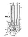
- FIG. 2shows a handpiece where the controls and video processing and even the video display (which provides the T.V. image for monitoring purposes) may be provided in the handpiece.
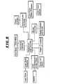
- FIG. 8shows the electronic components for carrying out the control and video processing functions.
- the handpieceis adapted to be held by its distal or rear end 32 in the hand of the treating physician.
- This end 32has a keypad with keys projecting from the surface of the housing for entry of laser control parameters, such as laser power, the duration of the laser bursts or pulses, and depth within the tissue of the focused spot as well as information as to the patient and the treatment afforded.
- laser control parameterssuch as laser power, the duration of the laser bursts or pulses, and depth within the tissue of the focused spot as well as information as to the patient and the treatment afforded.
- a trigger buttonwhich may operate the laser to turn it on and off and may also operate the shutter which controls the laser energy which is delivered through the window 18 at the proximal end of the handpiece 10.
- This triggermay be a two step switch which when depressed to the first step turns the laser on and to the second step actuates a motor which moves the shutter out of a position where it normally blocks the beam for safety purposes.
- the thumb of the operatormay be used to manipulate a trackball 36 which operates an encoder of the type in a computer mouse and provides the beam steering control, and sends signals to the motors of the beam deflecting system.
- a displaysuch as a liquid crystal display may be used to present the image which is viewed by the camera, if an external monitor such as the monitor 26 is not used.
- the resolution obtained by such a displayis less than may be desired for certain operations. Then an external large screen monitor 26 is more desirable.
- the displaymay also show the parameters which are entered by the keyboard such as laser power and pulse duration.
- a suitable operating laser power of 1/4 watt and a suitable pulse duration (the duration of the burst of CW, IR laser energy) of 1/4 secondis indicated on the display 40.
- FIG. 4 and FIG. 9there is shown a first lens 42 and a second lens 44 of telecentric optics.
- the opticshas an optical axis 46 which provides a focus at the plane of the photoreceptors (the image or visualization plane) of a video camera 48.
- This camerais preferably a CCD camera having its matrix (an X-Y matrix) located in the image plane 47.
- the front or first lens 42provides a front focus in the plane of the area under treatment (14 - FIG. 1) and a rear focus midway between the back plane of the planoconvex lenses 42 and 44 (that is, the surface or side of these lenses which is planar).
- the rear lens 44has its front focus in the visualization plane 47 and its rear focus midway between the planar surfaces of the lenses 42 and 44.
- the midpoint focusis at 49 and intersects the optical axis 46.
- the focus 49is the common rear and front focii of the lenses 42 and 44, respectively. Because the optics is telecentric, the central ray of the focused beam always remains parallel to the plane of the treatment area and the visualization plane 47, which are perpendicular to the optical axis 46, even as the beam is scanned over the treatment area. When the beam is retroreflected from the area it is focused in the visualization plane.
- the visualization planealso receives light which is returned through the telecentric lenses 42 and 44 and which is generated by an annular illuminating ring or lamp 52.
- This lamphas a broad spectrum of light but may contain a majority of its intensity in the infrared region including the wavelength of the laser light to allow visualization below the surface of the tissue. Then the entire area and even some of the surrounding area is visualized and an image thereof is obtained with the video camera 48.
- the lenses 42 and 44form part of the projection means, as does part of the beam deflection or steering means of the system.
- This deflection and steering meansis provided by a first mirror 54 which has an axis of rotation perpendicular to the optical axis 46 and through mid focal point 49 of the lenses 42 and 44.
- the deflecting or scan mirror 54is a polarization beam splitter which reflects the incoming laser beam in a direction to propagate out of the handpiece 10 through the window 18.
- the return lighthas a component with an opposite sense of polarization and passes through the scan mirror 54 to the visualization plane 47.
- the scan mirror 54provides scanning over a first, say the X coordinate of the cartesian coordinates which define the length and width of the area under treatment.
- Another scan mirror 56is rotatable about an axis 58. This mirror is tilted at an angle of approximately 45° such that a ray traveling parallel to the x-axis would be reflected into the plane of the diagram illustrated in FIG. 3.
- the mirror 56is carried by an arm 60 which is turned by the shaft (about the axis 58) of a galvanometer type motor 62, which may be a stepper motor.
- a similar motor 64rotates the first scan mirror 54.
- the scan mirror 56deflects the laser beam 12 along the other or Y coordinate.
- the beammay be located at any selected site in the treatment area and an image of the spot at the site is created at the visualization plane 47 of the camera 48.
- both steering and visualizationis accomplished simultaneously and automatically.
- the two mirror steering or deflection systemis generally of the type described in U.S. Patent 5,048,904 issued September 17, 1991 to J.I. Montague, which shows a two mirror scanner.
- the laser energyis delivered by the optical fiber cable 22 to a fiber ferrule or coupler 66 from which the incoming beam projects and is focused by a lens 68.
- Lens 68nominally collimates the beam.
- a focus mechanism 69which may be either manual or electromechanical, sets the depth below the surface that the laser light is focused. The focus mechanism 69 moves lens 68 in the z direction relative to ferrule 66.
- the beamis folded at a fold mirror 70 and is directed to the polarization sensitive scan mirror 54.
- the beamis then focused by the front lens 42 of the telecentric optics to a spot in the area being treated which may be referred to as the treatment plane.
- Focusing the beamincreases the irradiance of the beam as it propagates to its nominal focus at the spot in the treatment plane.
- the half angle of convergenceis equal to the arc sign of the numerical aperture of the lens 42 sin -1 (NA) where NA is the numerical aperture of the focused beam.
- NAthe numerical aperture of the focused beam.
- the half angle of convergenceis reduced to sin -1 (NA/n), where n is the refractive index of the tissue.
- the window 18is desirably of high thermal conductivity and is approximately matched to the refractive index of the skin or other tissue (n in the range of approximately 1.35 to 1.55).
- the absorption coefficient of the tissue in the layers under the surface to the treatment areais ⁇ a which is 0.1mm -1
- the scattering coefficient ⁇ sis 10mm -1 .
- the tissuemay have a anisotropy factor g of 0.985.
- the beam focused with a lens having a numerical aperture of .3provides a intensity or laser dose above the depth of focus at the treatment area (and the treatment plane) which is sufficient to avoid damage to the tissue above the treatment sites, in the foregoing example.
- a shutter 72is provided by an arm which is rotated in a plane perpendicular to the optical axis 46 by a motor 74, which may be similar to the motors 62 and 64.
- This shutter 72is shown in plan view in FIG. 5.
- the shutterhas two sets (a, b, c and 1, 2, 3) of three regions which provide different transmisivity during different modes or stages of operation of the system.
- the normal or unpowered position of the shutteris with the region 1 in the path of the retroreflective light to the visualization plane 47 in the camera and with the region a (a dense block or no hole at all through the shutter) intercepting the output beam from the coupler 66.
- This dense blockmay preferably include a photodetector used to monitor the beam power emanating from ferrule 66. Then the illumination from the lamp 52 can be turned on and the area viewed. This mode or stage of operation may be used to move the instrument to find the desired area without any laser illumination.
- the shutterWhen the area has been found the shutter is moved so that the incoming beam is intercepted at region b, containing a neutral density filter which attenuates the laser beam in the path of the output beam from the coupler 66.
- the region 2is then in the path of the return light from the spot where the laser beam is focused in the treatment plane.
- the region 2may be an open hole. This permits both visible viewing and viewing of the infrared (700 to 1300nm wavelength illumination) due to the laser beam.
- the systemutilizes the laser beam as a spotter or tracking beam to locate the sites to be treated, say a hair follicle or a part of a spider vein to be coagulated, or an adhesion between a tendon and its sheath.
- the shutteris moved to its furtherest position (in a counter clockwise direction in FIG. 5) about the axis 70 of rotation of the shaft 75 of the motor 74. Then, the output beam 66 passes through an open hole c, while a neutral density filter (region 3) is interposed in the return path to protect the television camera (especially the CCD sensor array) during the treatment pulse.
- a hand piece 100is shown which is identical so far as its visualization and beam projection system is concerned and like parts are identified by like referenced numerals.
- An external laseris not used. Rather a laser diode 102 is used to produce the infrared radiation.
- the output of the diodeis nominally colliminated by a lens 104 to provide a beam to the fold mirror 70 and thence to the deflection mirrors 56 and 54.
- the lens 104 mounted to focus mechanism 105which may be manual or electromechanical, sets the depth below the surface of the tissue to which the laser light is focused.
- the electronics on which the laser diode 102 may be mounted and also which contains the controller and video processing circuitryis a printed circuit board 106. The components of the circuitry will be more apparent from FIG. 8.
Landscapes
- Physics & Mathematics (AREA)
- Health & Medical Sciences (AREA)
- Surgery (AREA)
- Optics & Photonics (AREA)
- Life Sciences & Earth Sciences (AREA)
- Engineering & Computer Science (AREA)
- Molecular Biology (AREA)
- Nuclear Medicine, Radiotherapy & Molecular Imaging (AREA)
- Electromagnetism (AREA)
- Biomedical Technology (AREA)
- Heart & Thoracic Surgery (AREA)
- Medical Informatics (AREA)
- Otolaryngology (AREA)
- Animal Behavior & Ethology (AREA)
- General Health & Medical Sciences (AREA)
- Public Health (AREA)
- Veterinary Medicine (AREA)
- Laser Surgery Devices (AREA)
- Radiation-Therapy Devices (AREA)
Description
Claims (21)
- A system for thermolysis of dermatologicaltissue in an area under the surface thereof with visualizationof said area which comprises a housing which is sufficientlysmall to be hand held, a window in said housing providing aport for illumination emanating from within said housing anddisposed in proximity to the tissue surface above said area, means forprojecting a laser beam from said housing through said window,means in said projecting means for focusing said beam atselected locations in said area at spots sufficiently small incross-section and of power and duration of said beam to causelocalized thermolysis of the tissue at each of said spots,said projecting means also including means in said housing fordeflecting said beam to locate each of said spots at each of said selectedlocations one at a time and stop said beam, and means in said housing forvisualizing said area while said beam is deflected therebyverifying that each of said spots is at each of said selectedlocations, and wherein saidlaser beam is of a wavelength from 700 to 1300 nm.
- The system according to Claim 1 furthercomprising trigger means on said housing and projectingexternally thereof for enabling the projection of said beamwith sufficient power to cause thermolysis when it reachessaid selected locations.
- The system according to Claim 1 furthercomprising means including a manual control projectingexternally of said housing for operating said deflecting meansand for steering said beam to said selected locations.
- The system according to Claim 1 furthercomprising means in said housing including a keyboard havingkeys projecting externally of said housing for entering datafor control of beam parameters and information on patientsbeing treated.
- The system of Claim 1 having means in said housing for visualizing all ofsaid area while said beam is deflected thereby verifying said spot is stopped ateach of said selected locations before irradiation of the tissue thereat.
- The system according to Claim 1 furthercomprising telecentric optics having an optical axis extending through said window, said telecentric optics being included insaid focusing and visualization means, a first image planeperpendicular to said axis in said housing and the secondimage plane containing said area, said telecentric opticsprojecting said illumination in a direction generally parallelto said optical axis and perpendicular to said first andsecond planes.
- The system according to Claim 6 wherein saidvisualizing means comprises a photoreceptor disposed in saidfirst plane.
- The system according to Claim 7 wherein saidvisualizing means includes a CCD television camera having asensor array providing said photoreceptor, said array being insaid first plane.
- The system according to Claim 7 wherein saidvisualizing means further comprises a T.V. camera includingsaid photoreceptor and a monitor for displaying a T.V. pictureof the area imaged on said photoreceptor.
- The system according to Claim 1 wherein saidprojecting means for focusing and deflecting said beam tolocate said spot at said selected locations comprises scanningmeans which move said beam selectively along cartesiancoordinates (X and Y and Z) over said area and moving thefocus of said beam along a Z axis perpendicular to a planecontaining said X and Y coordinates.
- The system according to Claim 6 wherein saiddeflecting means comprises a first mirror rotatable about anaxis through said optical axis and perpendicular thereto fordeflecting said beam along one of two cartesian coordinates toeach of said selected locations, and a second mirror rotatableabout a second axis for deflecting said beam toward said firstmirror thereby scanning said beam along the other of saidcoordinates to each of said selected locations.
- The system according to Claim 6, wherein saiddeflecting means comprises a first mirror rotatable about anaxis through said optical axis and perpendicular thereto fordeflecting said beam along one of two cartesian coordinates (X and Y) to each of said selected locations, and a second mirrorrotatable about a second axis for deflecting said beam towardssaid first mirror thereby deflecting said beam along the otherof said coordinates to each of said selected locations, andsaid telecentric optics has a first lens disposed between saidaxis of rotation of said first mirror, which first lensfocuses said beam at said first plane, and a second lensbetween said axis of first scan mirror and.said second planefor focusing said beam at said second plane, said lenses alsohaving common foci where said axis of rotation of said firstmirror intersects said optical axis.
- The system according to Claim 1 wherein saidvisualization means includes a T.V. camera in said housing anda T.V. monitor connected to said camera for providing T.V.pictures of said area.
- The system according to Claim 5 wherein saidtissue is skin and said area is up to 5 mm from the surface ofthe skin.
- The system according to Claim 14 wherein saidlaser beam is produced in a burst of 0.25 second induration and has the power of 0.25 watts.
- The system according to Claim 1 wherein saidtissue comprises an inner layer of cells which defines spiderveins, and said means in said projecting means including saidfocusing means which is operative to focus at said locationswhich are coincident with different ones of said veins tothermolyze regions of each of said veins containingendothelium cells in each of said veins which comprise saidinner layer thereby causing each of said veins to collapse sothat blood therein is reabsorbed by the patient's body.
- The system according to Claim 16 wherein saidprojection means includes traching means used responsive to an image of saidarea for tracking said veins and enabling said laser tc causethermolysis of said veins at said locations as defined by saidtracking means.
- The system according to Claim 1 wherein saidtissue is in the bulb of a hair follicle and said projecting means includes means operative to make at least one of saidlocations and said spot coincident with said follicle wherebysaid follicle is cauterized by said beam at said spot.
- The system according to Claim 1 wherein saidprojection means includes a shutter, means for moving saidshutter so that different regions thereof selectively comeinto intercepting relationship with said beam, said regionshaving separate beam blocking, attenuating and transmissivematerial in said different regions.
- The system according to Claim 19 wherein saidregions which block, attenuate and transmit said beam arefirst regions of said shutter, and wherein said shutter has aplurality of second regions in the path of said beam uponretroflection thereof from said area, a first, a second and athird of said second regions respectively having a f ilter forblocking the wavelength of said beam, an opening fortransmitting said retroreflected beam and a material whichpartially blocks and attenuates said retroreflected beam inintensity, said first and second regions which block light ofthe wavelength of said beam being arranged on said shutter totogether intercept said projected and retroreflected beam,said first and second regions which attenuate and pass saidprojected and retroreflected beam being respectively arrangedon said shutter together to intercept said projected andretroreflected beam, and said first and second regions whichtransmit and attenuate said projected and retroreflected beam,respectively, being arranged together to intercept saidprojected and retroref lected beam.
- The system according to claim 1 wherein saidvisualizing means includes means for illuminating said entirearea with light which enables the creation of an image of said areawhile said projected beam is incident on said area so thatsaid area and said spots can be visualized.
Applications Claiming Priority (3)
| Application Number | Priority Date | Filing Date | Title |
|---|---|---|---|
| US94296 | 1993-07-21 | ||
| US08/094,296US5860967A (en) | 1993-07-21 | 1993-07-21 | Dermatological laser treatment system with electronic visualization of the area being treated |
| PCT/US1994/008169WO1995003089A1 (en) | 1993-07-21 | 1994-07-20 | Laser treatment system with electronic visualization |
Publications (3)
| Publication Number | Publication Date |
|---|---|
| EP0710136A1 EP0710136A1 (en) | 1996-05-08 |
| EP0710136A4 EP0710136A4 (en) | 1998-06-10 |
| EP0710136B1true EP0710136B1 (en) | 2004-02-04 |
Family
ID=22244345
Family Applications (1)
| Application Number | Title | Priority Date | Filing Date |
|---|---|---|---|
| EP94923982AExpired - LifetimeEP0710136B1 (en) | 1993-07-21 | 1994-07-20 | Laser treatment system with electronic visualization |
Country Status (6)
| Country | Link |
|---|---|
| US (2) | US5860967A (en) |
| EP (1) | EP0710136B1 (en) |
| JP (1) | JPH09501334A (en) |
| AU (1) | AU7401094A (en) |
| DE (1) | DE69433531T2 (en) |
| WO (1) | WO1995003089A1 (en) |
Cited By (1)
| Publication number | Priority date | Publication date | Assignee | Title |
|---|---|---|---|---|
| CN101646472A (en)* | 2007-03-30 | 2010-02-10 | 松下电工株式会社 | Hair growth control method and apparatus for the method |
Families Citing this family (208)
| Publication number | Priority date | Publication date | Assignee | Title |
|---|---|---|---|---|
| US5554153A (en)* | 1994-08-29 | 1996-09-10 | Cell Robotics, Inc. | Laser skin perforator |
| US5993439A (en)* | 1994-08-29 | 1999-11-30 | Cell Robotics, Inc. | Lens shield for laser skin perforation |
| AT403654B (en)* | 1994-12-01 | 1998-04-27 | Binder Michael Dr | DEVICE FOR THE OPTICAL EXAMINATION OF HUMAN SKIN AND THE SAME ASSIGNMENT EVALUATION DEVICE |
| AT401342B (en)* | 1995-01-17 | 1996-08-26 | Myles Handels Gmbh | SOFTLASER WITH INTEGRATED POINT DETECTOR FOR ACUPUNCTURE POINTS |
| US5759200A (en)* | 1996-09-04 | 1998-06-02 | Azar; Zion | Method of selective photothermolysis |
| US6214034B1 (en) | 1996-09-04 | 2001-04-10 | Radiancy, Inc. | Method of selective photothermolysis |
| US6424852B1 (en)* | 1996-10-18 | 2002-07-23 | Lucid, Inc. | System for confocal imaging within dermal tissue |
| US6745067B1 (en)* | 1998-09-14 | 2004-06-01 | Lucid, Inc. | System for marking the locations of imaged tissue with respect to the surface of the tissue |
| US20060095097A1 (en)* | 1996-10-30 | 2006-05-04 | Provectus Devicetech, Inc. | Treatment of pigmented tissue using optical energy |
| US7036516B1 (en) | 1996-10-30 | 2006-05-02 | Xantech Pharmaceuticals, Inc. | Treatment of pigmented tissues using optical energy |
| US8182473B2 (en)* | 1999-01-08 | 2012-05-22 | Palomar Medical Technologies | Cooling system for a photocosmetic device |
| US20060149343A1 (en)* | 1996-12-02 | 2006-07-06 | Palomar Medical Technologies, Inc. | Cooling system for a photocosmetic device |
| US6517532B1 (en) | 1997-05-15 | 2003-02-11 | Palomar Medical Technologies, Inc. | Light energy delivery head |
| US7204832B2 (en) | 1996-12-02 | 2007-04-17 | Pálomar Medical Technologies, Inc. | Cooling system for a photo cosmetic device |
| US6190376B1 (en) | 1996-12-10 | 2001-02-20 | Asah Medico A/S | Apparatus for tissue treatment |
| US5906609A (en)* | 1997-02-05 | 1999-05-25 | Sahar Technologies | Method for delivering energy within continuous outline |
| US5810801A (en)* | 1997-02-05 | 1998-09-22 | Candela Corporation | Method and apparatus for treating wrinkles in skin using radiation |
| US6200309B1 (en)* | 1997-02-13 | 2001-03-13 | Mcdonnell Douglas Corporation | Photodynamic therapy system and method using a phased array raman laser amplifier |
| ATE409005T1 (en)* | 1997-03-19 | 2008-10-15 | Lucid Inc | CELL SURGERY USING CONFOCAL MICROSCOPY |
| US6248102B1 (en)* | 1997-04-04 | 2001-06-19 | Keralase Ltd. | Method of hair removal by transcutaneous application of laser light |
| NO972244L (en)* | 1997-05-15 | 1998-11-16 | Photocure | Device for illumination of a defined area |
| ES2226133T3 (en) | 1997-05-15 | 2005-03-16 | Palomar Medical Technologies, Inc. | DERMATOLOGICAL TREATMENT DEVICE. |
| GB9710562D0 (en)* | 1997-05-23 | 1997-07-16 | Medical Laser Technologies Lim | Light delivery |
| US6117129A (en)* | 1997-05-30 | 2000-09-12 | Nidek Co., Ltd. | Laser treatment apparatus |
| USD472969S1 (en) | 1997-07-30 | 2003-04-08 | Wotan Wilden | Therapeutic laser light emitting device |
| US6068728A (en)* | 1997-08-28 | 2000-05-30 | Seagate Technology, Inc. | Laser texturing with reverse lens focusing system |
| US6074382A (en) | 1997-08-29 | 2000-06-13 | Asah Medico A/S | Apparatus for tissue treatment |
| WO2000053261A1 (en)* | 1999-03-08 | 2000-09-14 | Asah Medico A/S | An apparatus for tissue treatment and having a monitor for display of tissue features |
| ATE328642T1 (en)* | 1997-10-08 | 2006-06-15 | Gen Hospital Corp | PHOTOTHERAPEUTIC SYSTEMS |
| US6066129A (en)* | 1998-01-29 | 2000-05-23 | Larson; Dean W. | Medical laser control system |
| US6165170A (en)* | 1998-01-29 | 2000-12-26 | International Business Machines Corporation | Laser dermablator and dermablation |
| US6149644A (en)* | 1998-02-17 | 2000-11-21 | Altralight, Inc. | Method and apparatus for epidermal treatment with computer controlled moving focused infrared light |
| US6080146A (en)* | 1998-02-24 | 2000-06-27 | Altshuler; Gregory | Method and apparatus for hair removal |
| EP1066488A1 (en) | 1998-02-26 | 2001-01-10 | Lucid, Inc. | Confocal microscope for facilitating cryosurgery of tissue |
| ES2245506T3 (en) | 1998-03-12 | 2006-01-01 | Palomar Medical Technologies, Inc. | ELECTROMAGNETIC RADIATION APPLICATION SYSTEM ON SKIN. |
| DE19836649C2 (en)* | 1998-08-13 | 2002-12-19 | Zeiss Carl Meditec Ag | Medical handpiece |
| US6096066A (en)* | 1998-09-11 | 2000-08-01 | Light Sciences Limited Partnership | Conformal patch for administering light therapy to subcutaneous tumors |
| US6059820A (en) | 1998-10-16 | 2000-05-09 | Paradigm Medical Corporation | Tissue cooling rod for laser surgery |
| US6402739B1 (en)* | 1998-12-08 | 2002-06-11 | Y-Beam Technologies, Inc. | Energy application with cooling |
| SE522249C2 (en)* | 1999-01-13 | 2004-01-27 | Biolight Patent Holding Ab | Control device for controlling external processing by light |
| SE515992C2 (en)* | 1999-01-20 | 2001-11-05 | Biolight Patent Holding Ab | Light emitting organs for medical treatment are externalized by light |
| DE19903318A1 (en)* | 1999-01-28 | 2000-08-10 | Expo Med Jezischek Kg | Bracket for the laser optics of a laser |
| USD424197S (en)* | 1999-02-12 | 2000-05-02 | Thermolase Corporation | Laser handpiece housing |
| DE60001240D1 (en)* | 1999-02-26 | 2003-02-27 | Nidek Kk | Laserdepiliergerät |
| US6607523B1 (en) | 1999-03-19 | 2003-08-19 | Asah Medico A/S | Apparatus for tissue treatment |
| EP1087716B1 (en)* | 1999-04-14 | 2005-10-19 | Koninklijke Philips Electronics N.V. | Hair-removing device with a controllable laser source |
| US7101365B1 (en)* | 1999-05-25 | 2006-09-05 | I.T.L. Optronics, Ltd. | Laser for skin treatment |
| US6210425B1 (en)* | 1999-07-08 | 2001-04-03 | Light Sciences Corporation | Combined imaging and PDT delivery system |
| US6406474B1 (en)* | 1999-09-30 | 2002-06-18 | Ceramoptec Ind Inc | Device and method for application of radiation |
| KR100316124B1 (en)* | 1999-10-14 | 2001-12-12 | 김춘영 | Device for guiding a laser beam generated by a medical laser instrument |
| DE50014843D1 (en)* | 1999-11-18 | 2008-01-24 | Baumer Holding Ag | Optical angle and / or distance measuring module |
| DE19959698C2 (en)* | 1999-12-08 | 2002-01-10 | Asclepion Meditec Ag | Handpiece for cosmetic or medical treatment |
| US6419671B1 (en)* | 1999-12-23 | 2002-07-16 | Visx, Incorporated | Optical feedback system for vision correction |
| JP4495894B2 (en)* | 2000-01-25 | 2010-07-07 | パロマー・メディカル・テクノロジーズ・インコーポレーテッド | Device for medical treatment using long-term electromagnetic radiation |
| FR2804858B1 (en)* | 2000-02-11 | 2002-09-20 | Morente Juan Luis Benitez | COMPUTER-AIDED LASER HAIR REMOVAL DEVICE |
| US20030060810A1 (en) | 2000-02-16 | 2003-03-27 | Diego Syrowicz | Method and apparatus for treating and/or removing an undesired presence on the skin of an individual |
| JP2001238968A (en)* | 2000-03-01 | 2001-09-04 | Ya Man Ltd | Laser beam irradiation probe |
| US6436094B1 (en) | 2000-03-16 | 2002-08-20 | Laserscope, Inc. | Electromagnetic and laser treatment and cooling device |
| US6451010B1 (en)* | 2000-04-14 | 2002-09-17 | Lumenis Inc. | Zoom handpiece for laser surgery |
| AU2001257069A1 (en)* | 2000-04-17 | 2001-10-30 | Medelaser, Llc | Photostimulaton treatment apparatus and methods for use |
| US6544257B2 (en)* | 2000-07-03 | 2003-04-08 | Olympus Optical Co., Ltd. | Thermal treatment apparatus |
| WO2002009813A1 (en)* | 2000-07-31 | 2002-02-07 | El. En. S.P.A. | Method and device for epilation by ultrasound |
| GB2370229A (en)* | 2000-12-22 | 2002-06-26 | Icn Photonics Ltd | Light delivery system for improving the appearance of skin |
| US20020082466A1 (en)* | 2000-12-22 | 2002-06-27 | Jeongho Han | Laser surgical system with light source and video scope |
| US20080172047A1 (en)* | 2000-12-28 | 2008-07-17 | Palomar Medical Technologies, Inc. | Methods And Devices For Fractional Ablation Of Tissue |
| EP1700573A3 (en)* | 2000-12-28 | 2010-12-01 | Palomar Medical Technologies, Inc. | Apparatus for therapeutic EMR treatment of the skin |
| US6888319B2 (en)* | 2001-03-01 | 2005-05-03 | Palomar Medical Technologies, Inc. | Flashlamp drive circuit |
| US7922751B2 (en)* | 2004-02-04 | 2011-04-12 | Erchonia Corporation | Stand-alone scanning laser device |
| US7947067B2 (en)* | 2004-02-04 | 2011-05-24 | Erchonia Corporation | Scanning treatment laser with sweep beam spot and universal carriage |
| US8083785B2 (en) | 2001-03-02 | 2011-12-27 | Erchonia Corporation | Multi-probe laser device |
| WO2002069825A2 (en)* | 2001-03-02 | 2002-09-12 | Palomar Medical Technologies, Inc. | Apparatus and method for photocosmetic and photodermatological treatment |
| US7118588B2 (en)* | 2001-03-02 | 2006-10-10 | Kevin Tucek | Scanning treatment laser |
| JP4141260B2 (en)* | 2001-03-30 | 2008-08-27 | コーニンクレッカ フィリップス エレクトロニクス エヌ ヴィ | Skin treatment device with protected radiation output opening |
| CN1463188A (en)* | 2001-04-20 | 2003-12-24 | 皇家菲利浦电子有限公司 | Skin treating device with protection against rediation pulse overdose |
| US7217266B2 (en)* | 2001-05-30 | 2007-05-15 | Anderson R Rox | Apparatus and method for laser treatment with spectroscopic feedback |
| US6679837B2 (en)* | 2001-06-01 | 2004-01-20 | Intlas Ltd. | Laser light irradiation apparatus |
| JP2005500108A (en)* | 2001-08-15 | 2005-01-06 | リライアント テクノロジーズ,インコーポレイティド | Apparatus and method for thermal excision of biological tissue |
| US20040147984A1 (en)* | 2001-11-29 | 2004-07-29 | Palomar Medical Technologies, Inc. | Methods and apparatus for delivering low power optical treatments |
| US20050049582A1 (en)* | 2001-12-12 | 2005-03-03 | Debenedictis Leonard C. | Method and apparatus for fractional photo therapy of skin |
| US20040082940A1 (en)* | 2002-10-22 | 2004-04-29 | Michael Black | Dermatological apparatus and method |
| WO2003053269A1 (en)* | 2001-12-12 | 2003-07-03 | Bernstein Eric F | Laser treatment for reduction of pore size |
| US20030216719A1 (en)* | 2001-12-12 | 2003-11-20 | Len Debenedictis | Method and apparatus for treating skin using patterns of optical energy |
| US7540869B2 (en)* | 2001-12-27 | 2009-06-02 | Palomar Medical Technologies, Inc. | Method and apparatus for improved vascular related treatment |
| WO2003068064A1 (en)* | 2002-02-12 | 2003-08-21 | Science & Engineering Associates, Inc. | Cancer detection and adaptive dose optimization treatment system |
| US20080177359A1 (en)* | 2002-05-03 | 2008-07-24 | Advanced Light Technology, Llc. | Differential photochemical and photomechanical processing |
| US20060194164A1 (en)* | 2004-12-09 | 2006-08-31 | Palomar Medical Technologies, Inc. | Oral appliance with heat transfer mechanism |
| US20070239142A1 (en)* | 2006-03-10 | 2007-10-11 | Palomar Medical Technologies, Inc. | Photocosmetic device |
| WO2004000098A2 (en) | 2002-06-19 | 2003-12-31 | Palomar Medical Technologies, Inc. | Method and apparatus for treatment of cutaneous and subcutaneous conditions |
| CA2487987C (en)* | 2002-06-19 | 2010-04-13 | Palomar Medical Technologies, Inc. | Method and apparatus for photothermal treatment of tissue at depth |
| GB2390025B (en)* | 2002-06-28 | 2005-07-27 | Lynton Lasers Ltd | Dermatological treatment apparatus and method |
| US7001413B2 (en)* | 2002-07-03 | 2006-02-21 | Life Support Technologies, Inc. | Methods and apparatus for light therapy |
| US7201766B2 (en)* | 2002-07-03 | 2007-04-10 | Life Support Technologies, Inc. | Methods and apparatus for light therapy |
| WO2004007022A1 (en)* | 2002-07-11 | 2004-01-22 | Asah Medico A/S | A handpiece for tissue treatment |
| JP2006501960A (en)* | 2002-10-07 | 2006-01-19 | パロマー・メディカル・テクノロジーズ・インコーポレイテッド | Apparatus for photobiological stimulation |
| US20070213792A1 (en)* | 2002-10-07 | 2007-09-13 | Palomar Medical Technologies, Inc. | Treatment Of Tissue Volume With Radiant Energy |
| US20070219605A1 (en)* | 2006-03-20 | 2007-09-20 | Palomar Medical Technologies, Inc. | Treatment of tissue volume with radiant energy |
| US6916315B2 (en)* | 2002-10-07 | 2005-07-12 | Kenneth Lawrence Short | Methods of operating a photo-thermal epilation apparatus |
| EP2522294A2 (en) | 2002-10-23 | 2012-11-14 | Palomar Medical Technologies, Inc. | Phototreatment device for use with coolants and topical substances |
| AU2003301111A1 (en)* | 2002-12-20 | 2004-07-22 | Palomar Medical Technologies, Inc. | Apparatus for light treatment of acne and other disorders of follicles |
| EP1599147A2 (en)* | 2003-02-19 | 2005-11-30 | Palomar Medical Technologies, Inc. | Method and apparatus for treating pseudofolliculitis barbae |
| US7354433B2 (en)* | 2003-02-28 | 2008-04-08 | Advanced Light Technologies, Llc | Disinfection, destruction of neoplastic growth, and sterilization by differential absorption of electromagnetic energy |
| US20110040295A1 (en)* | 2003-02-28 | 2011-02-17 | Photometics, Inc. | Cancer treatment using selective photo-apoptosis |
| ATE497807T1 (en) | 2003-03-27 | 2011-02-15 | Gen Hospital Corp | DEVICE FOR DERMATOLOGICAL TREATMENT AND FRACTIONAL SURFACE RENEWAL OF THE SKIN |
| US20040199151A1 (en)* | 2003-04-03 | 2004-10-07 | Ceramoptec Industries, Inc. | Power regulated medical underskin irradiation treament system |
| US8251057B2 (en) | 2003-06-30 | 2012-08-28 | Life Support Technologies, Inc. | Hyperbaric chamber control and/or monitoring system and methods for using the same |
| JP4838716B2 (en)* | 2003-08-04 | 2011-12-14 | コーニンクレッカ フィリップス エレクトロニクス エヌ ヴィ | Device for shortening hairs by laser-induced photodestructive effect |
| US8870856B2 (en)* | 2003-08-25 | 2014-10-28 | Cutera, Inc. | Method for heating skin using light to provide tissue treatment |
| US7722600B2 (en)* | 2003-08-25 | 2010-05-25 | Cutera, Inc. | System and method for heating skin using light to provide tissue treatment |
| US8915906B2 (en)* | 2003-08-25 | 2014-12-23 | Cutera, Inc. | Method for treatment of post-partum abdominal skin redundancy or laxity |
| WO2005037234A2 (en)* | 2003-10-14 | 2005-04-28 | Homer Gregg S | Method and device for dermal retraction and collagen and elastin generation |
| US7309335B2 (en)* | 2003-12-31 | 2007-12-18 | Palomar Medical Technologies, Inc. | Dermatological treatment with visualization |
| US7090670B2 (en)* | 2003-12-31 | 2006-08-15 | Reliant Technologies, Inc. | Multi-spot laser surgical apparatus and method |
| US20080125837A1 (en)* | 2004-02-06 | 2008-05-29 | Therapy Products, Inc. | Noninvasive method for site-specific fat reduction with catalyst |
| EP2301471A1 (en) | 2004-04-01 | 2011-03-30 | The General Hospital Corporation | Method and apparatus for dermatological treatment and tissue reshaping |
| US20080132886A1 (en)* | 2004-04-09 | 2008-06-05 | Palomar Medical Technologies, Inc. | Use of fractional emr technology on incisions and internal tissues |
| JP2008500846A (en)* | 2004-04-09 | 2008-01-17 | パロマー メディカル テクノロジーズ,インク. | Method and product for making a grid of EMR-treated isolated points in tissue and use thereof |
| WO2005102201A1 (en)* | 2004-04-26 | 2005-11-03 | Koninklijke Philips Electronics N.V. | A hair removing device |
| US7761945B2 (en) | 2004-05-28 | 2010-07-27 | Life Support Technologies, Inc. | Apparatus and methods for preventing pressure ulcers in bedfast patients |
| US7413572B2 (en)* | 2004-06-14 | 2008-08-19 | Reliant Technologies, Inc. | Adaptive control of optical pulses for laser medicine |
| ATE513524T1 (en)* | 2004-07-09 | 2011-07-15 | Braun Gmbh | HAIR GROWTH MANIPULATION |
| US7837675B2 (en)* | 2004-07-22 | 2010-11-23 | Shaser, Inc. | Method and device for skin treatment with replaceable photosensitive window |
| CN100471464C (en)* | 2004-10-05 | 2009-03-25 | 皇家飞利浦电子股份有限公司 | Skin treatment equipment with radiation emission protection |
| US8277495B2 (en)* | 2005-01-13 | 2012-10-02 | Candela Corporation | Method and apparatus for treating a diseased nail |
| CN101132831A (en)* | 2005-02-18 | 2008-02-27 | 帕洛玛医疗技术公司 | Dermatological treatment device |
| US20060253176A1 (en)* | 2005-02-18 | 2006-11-09 | Palomar Medical Technologies, Inc. | Dermatological treatment device with deflector optic |
| US8529560B2 (en)* | 2005-03-04 | 2013-09-10 | The Invention Science Fund I, Llc | Hair treatment system |
| US8540701B2 (en)* | 2005-03-04 | 2013-09-24 | The Invention Science Fund I, Llc | Hair treatment system |
| US20060200114A1 (en)* | 2005-03-04 | 2006-09-07 | Searete Llc, A Limited Liability Corporation Of State Of Delaware | Hair removal system with light source array |
| US8679101B2 (en)* | 2005-03-04 | 2014-03-25 | The Invention Science Fund I, Llc | Method and system for temporary hair removal |
| US20060276859A1 (en)* | 2005-06-02 | 2006-12-07 | Searete Llc, A Limited Liability Corporation Of The State Of Delaware | Photopatterning of skin |
| US8157807B2 (en)* | 2005-06-02 | 2012-04-17 | The Invention Science Fund I, Llc | Skin treatment including patterned light |
| US7856985B2 (en) | 2005-04-22 | 2010-12-28 | Cynosure, Inc. | Method of treatment body tissue using a non-uniform laser beam |
| DE602006021744D1 (en)* | 2005-05-12 | 2011-06-16 | Koninkl Philips Electronics Nv | CONTROL DEVICE FOR HAIR GROWTH |
| US20070032846A1 (en)* | 2005-08-05 | 2007-02-08 | Bran Ferren | Holographic tattoo |
| US9055958B2 (en)* | 2005-06-29 | 2015-06-16 | The Invention Science Fund I, Llc | Hair modification using converging light |
| US20070038270A1 (en)* | 2005-07-05 | 2007-02-15 | Searete Llc, A Limited Liability Corporation Of The State Of Delaware | Multi step photopatterning of skin |
| US20070176262A1 (en)* | 2005-08-11 | 2007-08-02 | Ernest Sirkin | Series connection of a diode laser bar |
| US20070093798A1 (en)* | 2005-08-29 | 2007-04-26 | Reliant Technologies, Inc. | Method and Apparatus for Monitoring and Controlling Thermally Induced Tissue Treatment |
| US20070048340A1 (en)* | 2005-08-31 | 2007-03-01 | Searete Llc, A Limited Liability Corporation Of The State Of Delaware | Multi step patterning of a skin surface |
| US20070173799A1 (en)* | 2005-09-01 | 2007-07-26 | Hsia James C | Treatment of fatty tissue adjacent an eye |
| CN101309631A (en) | 2005-09-15 | 2008-11-19 | 帕洛玛医疗技术公司 | Skin optical characterization device |
| WO2007038567A1 (en)* | 2005-09-28 | 2007-04-05 | Candela Corporation | Treating cellulite |
| US20070083190A1 (en)* | 2005-10-11 | 2007-04-12 | Yacov Domankevitz | Compression device for a laser handpiece |
| US7891362B2 (en)* | 2005-12-23 | 2011-02-22 | Candela Corporation | Methods for treating pigmentary and vascular abnormalities in a dermal region |
| US8478386B2 (en) | 2006-01-10 | 2013-07-02 | Accuvein Inc. | Practitioner-mounted micro vein enhancer |
| US9854977B2 (en) | 2006-01-10 | 2018-01-02 | Accuvein, Inc. | Scanned laser vein contrast enhancer using a single laser, and modulation circuitry |
| US12295744B2 (en) | 2006-01-10 | 2025-05-13 | Accuvein, Inc. | Micro vein enhancer with two lasers and two optical detectors configured for removing surface topology |
| US8489178B2 (en) | 2006-06-29 | 2013-07-16 | Accuvein Inc. | Enhanced laser vein contrast enhancer with projection of analyzed vein data |
| US12408865B2 (en) | 2006-01-10 | 2025-09-09 | Accuvein Inc. | Vein imaging device with differential image resolution at the center and the extremities of the vein image |
| US10238294B2 (en) | 2006-06-29 | 2019-03-26 | Accuvein, Inc. | Scanned laser vein contrast enhancer using one laser |
| US8838210B2 (en) | 2006-06-29 | 2014-09-16 | AccuView, Inc. | Scanned laser vein contrast enhancer using a single laser |
| US11278240B2 (en) | 2006-01-10 | 2022-03-22 | Accuvein, Inc. | Trigger-actuated laser vein contrast enhancer |
| US12089951B2 (en) | 2006-01-10 | 2024-09-17 | AccuVeiw, Inc. | Scanned laser vein contrast enhancer with scanning correlated to target distance |
| US10813588B2 (en) | 2006-01-10 | 2020-10-27 | Accuvein, Inc. | Micro vein enhancer |
| US8255040B2 (en)* | 2006-06-29 | 2012-08-28 | Accuvein, Llc | Micro vein enhancer |
| US9492117B2 (en) | 2006-01-10 | 2016-11-15 | Accuvein, Inc. | Practitioner-mounted micro vein enhancer |
| US11253198B2 (en) | 2006-01-10 | 2022-02-22 | Accuvein, Inc. | Stand-mounted scanned laser vein contrast enhancer |
| WO2007095183A2 (en)* | 2006-02-13 | 2007-08-23 | Reliant Technologies, Inc. | Laser system for treatment of skin laxity |
| US20070194717A1 (en)* | 2006-02-17 | 2007-08-23 | Palomar Medical Technologies, Inc. | Lamp for use in a tissue treatment device |
| US20070212335A1 (en)* | 2006-03-07 | 2007-09-13 | Hantash Basil M | Treatment of alopecia by micropore delivery of stem cells |
| KR100649889B1 (en)* | 2006-03-27 | 2006-11-28 | 주식회사 루트로닉 | Irradiation apparatus and method for irradiating micro laser beam for fine partial peeling |
| WO2007117580A2 (en)* | 2006-04-06 | 2007-10-18 | Palomar Medical Technologies, Inc. | Apparatus and method for skin treatment with compression and decompression |
| US8246611B2 (en)* | 2006-06-14 | 2012-08-21 | Candela Corporation | Treatment of skin by spatial modulation of thermal heating |
| GB2439286B (en)* | 2006-06-22 | 2010-09-15 | Dezac Group Ltd | Apparatus and methods for skin treatment |
| US8594770B2 (en) | 2006-06-29 | 2013-11-26 | Accuvein, Inc. | Multispectral detection and presentation of an object's characteristics |
| US8463364B2 (en)* | 2009-07-22 | 2013-06-11 | Accuvein Inc. | Vein scanner |
| US8730321B2 (en) | 2007-06-28 | 2014-05-20 | Accuvein, Inc. | Automatic alignment of a contrast enhancement system |
| US8665507B2 (en)* | 2006-06-29 | 2014-03-04 | Accuvein, Inc. | Module mounting mirror endoscopy |
| US8244333B2 (en)* | 2006-06-29 | 2012-08-14 | Accuvein, Llc | Scanned laser vein contrast enhancer |
| PL2043545T3 (en)* | 2006-07-13 | 2016-04-29 | Reliant Tech Llc | Apparatus for adjustable fractional optical dermatological treatment |
| US8260401B2 (en)* | 2006-07-26 | 2012-09-04 | University Of Rochester | Non-invasive in-vivo imaging of mechanoreceptors in skin using confocal microscopy |
| US7586957B2 (en) | 2006-08-02 | 2009-09-08 | Cynosure, Inc | Picosecond laser apparatus and methods for its operation and use |
| US20080058782A1 (en)* | 2006-08-29 | 2008-03-06 | Reliant Technologies, Inc. | Method and apparatus for monitoring and controlling density of fractional tissue treatments |
| US20080161782A1 (en)* | 2006-10-26 | 2008-07-03 | Reliant Technologies, Inc. | Micropore delivery of active substances |
| US20080154247A1 (en)* | 2006-12-20 | 2008-06-26 | Reliant Technologies, Inc. | Apparatus and method for hair removal and follicle devitalization |
| US7815630B2 (en)* | 2007-01-25 | 2010-10-19 | Biolase Technology, Inc. | Target-close electromagnetic energy emitting device |
| US20080186591A1 (en)* | 2007-02-01 | 2008-08-07 | Palomar Medical Technologies, Inc. | Dermatological device having a zoom lens system |
| US20080221649A1 (en)* | 2007-03-09 | 2008-09-11 | Agustina Echague | Method of sequentially treating tissue |
| US20080242967A1 (en)* | 2007-03-27 | 2008-10-02 | Ethicon Endo-Surgery, Inc. | Medical imaging and therapy utilizing a scanned beam system operating at multiple wavelengths |
| JP2008259631A (en)* | 2007-04-11 | 2008-10-30 | Oyo Kogaku Kenkyusho | Method for removing subcutaneous tissue |
| WO2008154007A1 (en)* | 2007-06-08 | 2008-12-18 | Cynosure, Inc. | Surgical waveguide |
| US9474576B2 (en)* | 2007-10-05 | 2016-10-25 | The Research Foundation For The State University Of New York | Coherent imaging fiber based hair removal device |
| US20090132012A1 (en)* | 2007-11-16 | 2009-05-21 | Therapy Products, Inc. | Method for pretreating patient before surgery |
| EP2258301A3 (en) | 2008-03-11 | 2013-04-17 | Shaser, Inc. | Enhancing optical radiation systems used in dermatologic treatments |
| US8939966B2 (en)* | 2008-08-21 | 2015-01-27 | University Of Florida Research Foundation, Inc. | Differential laser-induced perturbation (DLIP) for bioimaging and chemical sensing |
| US20100196497A1 (en)* | 2009-02-02 | 2010-08-05 | Therapy Products, Inc. | Method of Treating Tissue Using Platelet-Rich Plasma in Combination with Low-Level Laser Therapy |
| US9061109B2 (en) | 2009-07-22 | 2015-06-23 | Accuvein, Inc. | Vein scanner with user interface |
| US9919168B2 (en) | 2009-07-23 | 2018-03-20 | Palomar Medical Technologies, Inc. | Method for improvement of cellulite appearance |
| US8702688B2 (en)* | 2009-10-06 | 2014-04-22 | Cardiofocus, Inc. | Cardiac ablation image analysis system and process |
| IL201369A0 (en)* | 2009-10-11 | 2010-05-31 | Michael Slatkine | A bermatology apparatus |
| US20110190745A1 (en)* | 2009-12-04 | 2011-08-04 | Uebelhoer Nathan S | Treatment of sweat glands |
| US8518094B2 (en)* | 2010-03-02 | 2013-08-27 | Bwt Property, Inc. | Precisely guided phototherapy apparatus |
| US9017316B2 (en)* | 2010-07-26 | 2015-04-28 | Lumenis Ltd. | Distance estimation between a fiber end and a tissue using numerical aperture modulation |
| TWI450742B (en)* | 2011-03-15 | 2014-09-01 | Crystalvue Medical Corp | Optical apparatus |
| WO2013120095A1 (en)* | 2012-02-10 | 2013-08-15 | Nomir Medical Technologies | Near-infrared enhancement of circadian and ultradian spatiotemporal cellular coordination in the human integumentary system |
| US9833146B2 (en)* | 2012-04-17 | 2017-12-05 | Covidien Lp | Surgical system and method of use of the same |
| EP2839552A4 (en) | 2012-04-18 | 2015-12-30 | Cynosure Inc | PICOSECOND LASER APPARATUS AND METHOD OF PROCESSING TARGET TISSUES USING THE SAME |
| JP2013248323A (en)* | 2012-06-04 | 2013-12-12 | Osada Res Inst Ltd | Laser therapeutic apparatus |
| TW201400864A (en) | 2012-06-27 | 2014-01-01 | Metal Ind Res & Dev Ct | Optical scanning device |
| US9072426B2 (en) | 2012-08-02 | 2015-07-07 | AccuVein, Inc | Device for detecting and illuminating vasculature using an FPGA |
| US10517483B2 (en) | 2012-12-05 | 2019-12-31 | Accuvein, Inc. | System for detecting fluorescence and projecting a representative image |
| US10285757B2 (en) | 2013-03-15 | 2019-05-14 | Cynosure, Llc | Picosecond optical radiation systems and methods of use |
| US11433254B2 (en)* | 2013-03-15 | 2022-09-06 | Pavel V. Efremkin | Apparatus and method for treatment of wounds and skin medical conditions at a predetermined skin area |
| WO2017152049A1 (en)* | 2016-03-04 | 2017-09-08 | Accure Medical, Llc | Systems and methods for treatment of fungus |
| WO2019165426A1 (en) | 2018-02-26 | 2019-08-29 | Cynosure, Inc. | Q-switched cavity dumped sub-nanosecond laser |
| JP2021520247A (en)* | 2018-04-03 | 2021-08-19 | コンバージェント デンタル, インコーポレイテッド | Laser system for surgical applications |
| WO2021086928A1 (en) | 2019-10-28 | 2021-05-06 | President And Fellows Of Harvard College | Compact laser-steering end effector |
| KR102736408B1 (en)* | 2022-04-25 | 2024-12-02 | 주식회사 루트로닉 | An laser treatment apparatus and light transfer member |
Citations (2)
| Publication number | Priority date | Publication date | Assignee | Title |
|---|---|---|---|---|
| WO1987006478A1 (en)* | 1986-04-30 | 1987-11-05 | Institut National De La Sante Et De La Recherche M | Systematized treatment instrument, using particularly laser energy, useful for example in dermatology |
| US5098426A (en)* | 1989-02-06 | 1992-03-24 | Phoenix Laser Systems, Inc. | Method and apparatus for precision laser surgery |
Family Cites Families (22)
| Publication number | Priority date | Publication date | Assignee | Title |
|---|---|---|---|---|
| US3538919A (en)* | 1967-04-07 | 1970-11-10 | Gregory System Inc | Depilation by means of laser energy |
| US3693623A (en)* | 1970-12-25 | 1972-09-26 | Gregory System Inc | Photocoagulation means and method for depilation |
| US3769963A (en)* | 1972-03-31 | 1973-11-06 | L Goldman | Instrument for performing laser micro-surgery and diagnostic transillumination of living human tissue |
| US3834391A (en)* | 1973-01-19 | 1974-09-10 | Block Carol Ltd | Method and apparatus for photoepilation |
| US4289378A (en)* | 1978-06-21 | 1981-09-15 | Ernst Remy | Apparatus for adjusting the focal point of an operating laser beam focused by an objective |
| US4388924A (en)* | 1981-05-21 | 1983-06-21 | Weissman Howard R | Method for laser depilation |
| GB2123287B (en)* | 1982-07-09 | 1986-03-05 | Anna Gunilla Sutton | Depilaton device |
| US4854320A (en)* | 1983-10-06 | 1989-08-08 | Laser Surgery Software, Inc. | Laser healing method and apparatus |
| FR2561515A1 (en)* | 1984-03-21 | 1985-09-27 | Amar Roger | Automated device intended for applying infrared laser beams to adipose tissues for the purpose of cosmetic treatment of the body |
| IL75998A0 (en)* | 1984-08-07 | 1985-12-31 | Medical Laser Research & Dev C | Laser system for providing target tissue specific energy deposition |
| DE3577026D1 (en)* | 1984-10-25 | 1990-05-10 | Candela Laser Corp | TUNABLE LONG-PULSE DYE LASER. |
| US5336217A (en)* | 1986-04-24 | 1994-08-09 | Institut National De La Sante Et De La Recherche Medicale (Insepm) | Process for treatment by irradiating an area of a body, and treatment apparatus usable in dermatology for the treatment of cutaneous angio dysplasias |
| US4786155A (en)* | 1986-12-16 | 1988-11-22 | Fantone Stephen D | Operating microscope providing an image of an obscured object |
| EP0293126A1 (en)* | 1987-05-20 | 1988-11-30 | Keeler Limited | Photocoagulation apparatus |
| US5112328A (en)* | 1988-01-25 | 1992-05-12 | Refractive Laser Research & Development Program, Ltd. | Method and apparatus for laser surgery |
| US4901718A (en)* | 1988-02-02 | 1990-02-20 | Intelligent Surgical Lasers | 3-Dimensional laser beam guidance system |
| US4928695A (en)* | 1989-02-17 | 1990-05-29 | Leon Goldman | Laser diagnostic and treatment device |
| IL89874A0 (en)* | 1989-04-06 | 1989-12-15 | Nissim Nejat Danon | Apparatus for computerized laser surgery |
| US5059192A (en)* | 1990-04-24 | 1991-10-22 | Nardo Zaias | Method of hair depilation |
| US5048904A (en)* | 1990-07-06 | 1991-09-17 | General Scanning, Inc. | Two-mirror scanner with pincushion error correction |
| AU651374B2 (en)* | 1990-08-22 | 1994-07-21 | Visx Incorporated | System for scanning a surgical laser beam |
| US5474549A (en)* | 1991-07-09 | 1995-12-12 | Laserscope | Method and system for scanning a laser beam for controlled distribution of laser dosage |
- 1993
- 1993-07-21USUS08/094,296patent/US5860967A/ennot_activeExpired - Lifetime
- 1994
- 1994-07-20AUAU74010/94Apatent/AU7401094A/ennot_activeAbandoned
- 1994-07-20JPJP7505286Apatent/JPH09501334A/enactivePending
- 1994-07-20EPEP94923982Apatent/EP0710136B1/ennot_activeExpired - Lifetime
- 1994-07-20WOPCT/US1994/008169patent/WO1995003089A1/enactiveIP Right Grant
- 1994-07-20DEDE69433531Tpatent/DE69433531T2/ennot_activeExpired - Fee Related
- 1995
- 1995-02-27USUS08/395,223patent/US5653706A/ennot_activeExpired - Lifetime
Patent Citations (2)
| Publication number | Priority date | Publication date | Assignee | Title |
|---|---|---|---|---|
| WO1987006478A1 (en)* | 1986-04-30 | 1987-11-05 | Institut National De La Sante Et De La Recherche M | Systematized treatment instrument, using particularly laser energy, useful for example in dermatology |
| US5098426A (en)* | 1989-02-06 | 1992-03-24 | Phoenix Laser Systems, Inc. | Method and apparatus for precision laser surgery |
Cited By (1)
| Publication number | Priority date | Publication date | Assignee | Title |
|---|---|---|---|---|
| CN101646472A (en)* | 2007-03-30 | 2010-02-10 | 松下电工株式会社 | Hair growth control method and apparatus for the method |
Also Published As
| Publication number | Publication date |
|---|---|
| WO1995003089A1 (en) | 1995-02-02 |
| AU7401094A (en) | 1995-02-20 |
| JPH09501334A (en) | 1997-02-10 |
| DE69433531T2 (en) | 2004-09-30 |
| EP0710136A4 (en) | 1998-06-10 |
| EP0710136A1 (en) | 1996-05-08 |
| US5860967A (en) | 1999-01-19 |
| DE69433531D1 (en) | 2004-03-11 |
| US5653706A (en) | 1997-08-05 |
Similar Documents
| Publication | Publication Date | Title |
|---|---|---|
| EP0710136B1 (en) | Laser treatment system with electronic visualization | |
| US6676654B1 (en) | Apparatus for tissue treatment and having a monitor for display of tissue features | |
| US3769963A (en) | Instrument for performing laser micro-surgery and diagnostic transillumination of living human tissue | |
| US6383177B1 (en) | Apparatus for tissue treatment | |
| US10022269B2 (en) | Patterned laser treatment | |
| EP1003429B1 (en) | Cellular surgery utilizing confocal microscopy | |
| KR100454522B1 (en) | Laser dermablator and dermablation | |
| US6533776B2 (en) | Apparatus for tissue treatment | |
| US20030036680A1 (en) | Method and apparatus for thermal ablation of biological tissue using a scanning laser beam with real-time video monitoring and monitoring of therapeutic treatment parameters | |
| US20060253176A1 (en) | Dermatological treatment device with deflector optic | |
| EP1562468A2 (en) | Scanning laser ophthalmoscope optimized for selective retinal microphotocoagulation | |
| WO1989011260A1 (en) | Handpiece and related apparatus for laser surgery and dentistry | |
| AU2002313748A1 (en) | Method and apparatus for thermal ablation of biological tissue |
Legal Events
| Date | Code | Title | Description |
|---|---|---|---|
| PUAI | Public reference made under article 153(3) epc to a published international application that has entered the european phase | Free format text:ORIGINAL CODE: 0009012 | |
| 17P | Request for examination filed | Effective date:19960119 | |
| AK | Designated contracting states | Kind code of ref document:A1 Designated state(s):BE CH DE DK ES FR GB IE IT LI MC NL PT SE | |
| A4 | Supplementary search report drawn up and despatched | ||
| AK | Designated contracting states | Kind code of ref document:A4 Designated state(s):BE CH DE DK ES FR GB IE IT LI MC NL PT SE | |
| RHK1 | Main classification (correction) | Ipc:A61N 5/06 | |
| 17Q | First examination report despatched | Effective date:20010613 | |
| GRAP | Despatch of communication of intention to grant a patent | Free format text:ORIGINAL CODE: EPIDOSNIGR1 | |
| GRAS | Grant fee paid | Free format text:ORIGINAL CODE: EPIDOSNIGR3 | |
| GRAA | (expected) grant | Free format text:ORIGINAL CODE: 0009210 | |
| RAP1 | Party data changed (applicant data changed or rights of an application transferred) | Owner name:LUCID, INC. | |
| AK | Designated contracting states | Kind code of ref document:B1 Designated state(s):BE CH DE DK ES FR GB IE IT LI MC NL PT SE | |
| PG25 | Lapsed in a contracting state [announced via postgrant information from national office to epo] | Ref country code:NL Free format text:LAPSE BECAUSE OF FAILURE TO SUBMIT A TRANSLATION OF THE DESCRIPTION OR TO PAY THE FEE WITHIN THE PRESCRIBED TIME-LIMIT Effective date:20040204 Ref country code:LI Free format text:LAPSE BECAUSE OF FAILURE TO SUBMIT A TRANSLATION OF THE DESCRIPTION OR TO PAY THE FEE WITHIN THE PRESCRIBED TIME-LIMIT Effective date:20040204 Ref country code:IT Free format text:LAPSE BECAUSE OF FAILURE TO SUBMIT A TRANSLATION OF THE DESCRIPTION OR TO PAY THE FEE WITHIN THE PRE;WARNING: LAPSES OF ITALIAN PATENTS WITH EFFECTIVE DATE BEFORE 2007 MAY HAVE OCCURRED AT ANY TIME BEFORE 2007. THE CORRECT EFFECTIVE DATE MAY BE DIFFERENT FROM THE ONE RECORDED.SCRIBED TIME-LIMIT Effective date:20040204 Ref country code:FR Free format text:LAPSE BECAUSE OF FAILURE TO SUBMIT A TRANSLATION OF THE DESCRIPTION OR TO PAY THE FEE WITHIN THE PRESCRIBED TIME-LIMIT Effective date:20040204 Ref country code:CH Free format text:LAPSE BECAUSE OF FAILURE TO SUBMIT A TRANSLATION OF THE DESCRIPTION OR TO PAY THE FEE WITHIN THE PRESCRIBED TIME-LIMIT Effective date:20040204 Ref country code:BE Free format text:LAPSE BECAUSE OF FAILURE TO SUBMIT A TRANSLATION OF THE DESCRIPTION OR TO PAY THE FEE WITHIN THE PRESCRIBED TIME-LIMIT Effective date:20040204 | |
| REG | Reference to a national code | Ref country code:GB Ref legal event code:FG4D | |
| REG | Reference to a national code | Ref country code:CH Ref legal event code:EP | |
| REG | Reference to a national code | Ref country code:IE Ref legal event code:FG4D | |
| REF | Corresponds to: | Ref document number:69433531 Country of ref document:DE Date of ref document:20040311 Kind code of ref document:P | |
| PG25 | Lapsed in a contracting state [announced via postgrant information from national office to epo] | Ref country code:SE Free format text:LAPSE BECAUSE OF FAILURE TO SUBMIT A TRANSLATION OF THE DESCRIPTION OR TO PAY THE FEE WITHIN THE PRESCRIBED TIME-LIMIT Effective date:20040504 Ref country code:DK Free format text:LAPSE BECAUSE OF FAILURE TO SUBMIT A TRANSLATION OF THE DESCRIPTION OR TO PAY THE FEE WITHIN THE PRESCRIBED TIME-LIMIT Effective date:20040504 | |
| PG25 | Lapsed in a contracting state [announced via postgrant information from national office to epo] | Ref country code:ES Free format text:LAPSE BECAUSE OF FAILURE TO SUBMIT A TRANSLATION OF THE DESCRIPTION OR TO PAY THE FEE WITHIN THE PRESCRIBED TIME-LIMIT Effective date:20040515 | |
| PG25 | Lapsed in a contracting state [announced via postgrant information from national office to epo] | Ref country code:IE Free format text:LAPSE BECAUSE OF NON-PAYMENT OF DUE FEES Effective date:20040720 Ref country code:GB Free format text:LAPSE BECAUSE OF NON-PAYMENT OF DUE FEES Effective date:20040720 | |
| PG25 | Lapsed in a contracting state [announced via postgrant information from national office to epo] | Ref country code:MC Free format text:LAPSE BECAUSE OF NON-PAYMENT OF DUE FEES Effective date:20040731 | |
| NLV1 | Nl: lapsed or annulled due to failure to fulfill the requirements of art. 29p and 29m of the patents act | ||
| REG | Reference to a national code | Ref country code:CH Ref legal event code:PL | |
| PLBE | No opposition filed within time limit | Free format text:ORIGINAL CODE: 0009261 | |
| STAA | Information on the status of an ep patent application or granted ep patent | Free format text:STATUS: NO OPPOSITION FILED WITHIN TIME LIMIT | |
| 26N | No opposition filed | Effective date:20041105 | |
| EN | Fr: translation not filed | ||
| PG25 | Lapsed in a contracting state [announced via postgrant information from national office to epo] | Ref country code:DE Free format text:LAPSE BECAUSE OF NON-PAYMENT OF DUE FEES Effective date:20050201 | |
| GBPC | Gb: european patent ceased through non-payment of renewal fee | Effective date:20040720 | |
| REG | Reference to a national code | Ref country code:IE Ref legal event code:MM4A | |
| PG25 | Lapsed in a contracting state [announced via postgrant information from national office to epo] | Ref country code:PT Free format text:LAPSE BECAUSE OF NON-PAYMENT OF DUE FEES Effective date:20040704 |