EP0707132B1 - Rotary drill bit - Google Patents
Rotary drill bitDownload PDFInfo
- Publication number
- EP0707132B1 EP0707132B1EP95306937AEP95306937AEP0707132B1EP 0707132 B1EP0707132 B1EP 0707132B1EP 95306937 AEP95306937 AEP 95306937AEP 95306937 AEP95306937 AEP 95306937AEP 0707132 B1EP0707132 B1EP 0707132B1
- Authority
- EP
- European Patent Office
- Prior art keywords
- channel
- drill bit
- nozzle
- passage
- opening
- Prior art date
- Legal status (The legal status is an assumption and is not a legal conclusion. Google has not performed a legal analysis and makes no representation as to the accuracy of the status listed.)
- Expired - Lifetime
Links
- 238000005553drillingMethods0.000claimsdescription37
- 239000012530fluidSubstances0.000claimsdescription34
- 230000015572biosynthetic processEffects0.000claimsdescription9
- 238000005755formation reactionMethods0.000claimsdescription9
- 238000004140cleaningMethods0.000claimsdescription3
- 238000001816coolingMethods0.000claimsdescription3
- 238000004891communicationMethods0.000claimsdescription2
- 230000002093peripheral effectEffects0.000description4
- UONOETXJSWQNOL-UHFFFAOYSA-Ntungsten carbideChemical compound[W+]#[C-]UONOETXJSWQNOL-UHFFFAOYSA-N0.000description4
- 229910003460diamondInorganic materials0.000description3
- 239000010432diamondSubstances0.000description3
- 239000000758substrateSubstances0.000description3
- 238000005299abrasionMethods0.000description2
- 229910000831SteelInorganic materials0.000description1
- 230000004323axial lengthEffects0.000description1
- 239000011230binding agentSubstances0.000description1
- 239000000969carrierSubstances0.000description1
- 238000010276constructionMethods0.000description1
- 239000011159matrix materialSubstances0.000description1
- 229910052751metalInorganic materials0.000description1
- 239000002184metalSubstances0.000description1
- 229910001092metal group alloyInorganic materials0.000description1
- 238000000034methodMethods0.000description1
- 230000035515penetrationEffects0.000description1
- 239000000843powderSubstances0.000description1
- 238000004663powder metallurgyMethods0.000description1
- 239000007787solidSubstances0.000description1
- 239000010959steelSubstances0.000description1
Images


Classifications
- E—FIXED CONSTRUCTIONS
- E21—EARTH OR ROCK DRILLING; MINING
- E21B—EARTH OR ROCK DRILLING; OBTAINING OIL, GAS, WATER, SOLUBLE OR MELTABLE MATERIALS OR A SLURRY OF MINERALS FROM WELLS
- E21B10/00—Drill bits
- E21B10/60—Drill bits characterised by conduits or nozzles for drilling fluids
- E21B10/602—Drill bits characterised by conduits or nozzles for drilling fluids the bit being a rotary drag type bit with blades
- E—FIXED CONSTRUCTIONS
- E21—EARTH OR ROCK DRILLING; MINING
- E21B—EARTH OR ROCK DRILLING; OBTAINING OIL, GAS, WATER, SOLUBLE OR MELTABLE MATERIALS OR A SLURRY OF MINERALS FROM WELLS
- E21B10/00—Drill bits
- E—FIXED CONSTRUCTIONS
- E21—EARTH OR ROCK DRILLING; MINING
- E21B—EARTH OR ROCK DRILLING; OBTAINING OIL, GAS, WATER, SOLUBLE OR MELTABLE MATERIALS OR A SLURRY OF MINERALS FROM WELLS
- E21B10/00—Drill bits
- E21B10/46—Drill bits characterised by wear resisting parts, e.g. diamond inserts
- E21B10/54—Drill bits characterised by wear resisting parts, e.g. diamond inserts the bit being of the rotary drag type, e.g. fork-type bits
- E21B10/55—Drill bits characterised by wear resisting parts, e.g. diamond inserts the bit being of the rotary drag type, e.g. fork-type bits with preformed cutting elements
- E—FIXED CONSTRUCTIONS
- E21—EARTH OR ROCK DRILLING; MINING
- E21B—EARTH OR ROCK DRILLING; OBTAINING OIL, GAS, WATER, SOLUBLE OR MELTABLE MATERIALS OR A SLURRY OF MINERALS FROM WELLS
- E21B10/00—Drill bits
- E21B10/46—Drill bits characterised by wear resisting parts, e.g. diamond inserts
- E21B10/56—Button-type inserts
- E21B10/567—Button-type inserts with preformed cutting elements mounted on a distinct support, e.g. polycrystalline inserts
- E—FIXED CONSTRUCTIONS
- E21—EARTH OR ROCK DRILLING; MINING
- E21B—EARTH OR ROCK DRILLING; OBTAINING OIL, GAS, WATER, SOLUBLE OR MELTABLE MATERIALS OR A SLURRY OF MINERALS FROM WELLS
- E21B10/00—Drill bits
- E21B10/60—Drill bits characterised by conduits or nozzles for drilling fluids
- E—FIXED CONSTRUCTIONS
- E21—EARTH OR ROCK DRILLING; MINING
- E21B—EARTH OR ROCK DRILLING; OBTAINING OIL, GAS, WATER, SOLUBLE OR MELTABLE MATERIALS OR A SLURRY OF MINERALS FROM WELLS
- E21B17/00—Drilling rods or pipes; Flexible drill strings; Kellies; Drill collars; Sucker rods; Cables; Casings; Tubings
- E21B17/10—Wear protectors; Centralising devices, e.g. stabilisers
- E21B17/1057—Centralising devices with rollers or with a relatively rotating sleeve
- E21B17/1064—Pipes or rods with a relatively rotating sleeve
- E—FIXED CONSTRUCTIONS
- E21—EARTH OR ROCK DRILLING; MINING
- E21B—EARTH OR ROCK DRILLING; OBTAINING OIL, GAS, WATER, SOLUBLE OR MELTABLE MATERIALS OR A SLURRY OF MINERALS FROM WELLS
- E21B17/00—Drilling rods or pipes; Flexible drill strings; Kellies; Drill collars; Sucker rods; Cables; Casings; Tubings
- E21B17/10—Wear protectors; Centralising devices, e.g. stabilisers
- E21B17/1092—Gauge section of drill bits
Definitions
- the inventionrelates to rotary drill bits for use in drilling holes in subsurface formations, and of the kind comprising a bit body having a leading face and a gauge region, a plurality of blades formed on the leading face of the bit and extending outwardly away from the axis of the bit towards the gauge region so as to define between the blades a plurality of fluid channels leading towards the gauge region, a plurality of cutting elements mounted along each blade, and a plurality of nozzles in the bit body for supplying drilling fluids to the channels for cleaning and cooling the cutting elements.
- the inventionis particularly, but not exclusively, applicable to drill bits in which some or all of the cutters are preform (PDC) cutters each formed, at least in part, from polycrystalline diamond.
- PDCpreform
- One common form of cuttercomprises a tablet, usually circular or part circular, made up of a superhard table of polycrystalline diamond, providing the front cutting face of the element, bonded to a substrate which is usually of cemented tungsten carbide.
- the bit bodymay be machined from solid metal, usually steel, or may be moulded using a powder metallurgy process in which tungsten carbide powder is infiltrated with metal alloy binder inner furnace so as to form a hard matrix.
- the gauge region of the drill bitis formed by a plurality of kickers which are spaced apart around the outer periphery of the bit body and are formed with bearing surfaces which, in use, bear against the wall of the bore hole.
- the kickersgenerally form continuations of the respective blades, and the spaces between the kickers define junk slots with which the channels between the blades communicate.. Drilling fluid flowing outwardly along each channel flows into the junk slot at the end of the channel and passes upwardly through the junk slot into the annulus between the drill string and the wall of the borehole.
- PDC bitsWhile such PDC bits have been very successful in drilling relatively soft formations, they have been less successful in drilling harder formations, and soft formations which include harder or occlusions or stringers. Although good rates of penetration are possible in harder formations, the PDC cutters may suffer accelerated wear and bit life can be too short to be commercially acceptable.
- US 4440247 and US 4733735disclose arrangements in which an enclosed passage extends between an opening located in a channel between blades of the bit and an outlet which communicates with the annulus between the drill string and the wall of the borehole being drilled.
- the openingis located at a radius adjacent the axis of the bit.
- the present inventionprovides arrangements whereby the bearing surface area of the gauge region of a drill bit of the kind first referred to maybe increased without the above-mentioned disadvantages, and which may also give rise to other advantages.
- a nozzlefor supplying drilling fluid, and said nozzle may be at least partly directed towards said opening so as to deliver drilling fluid through said opening and into and inwardly along said one channel.
- the nozzlemay be at least partly directed towards said outlet from the passage, so as to deliver drilling fluid through said outlet to the annulus.
- the nozzlemay be mounted in a socket in a wall of said passage, the axis of the socket and of the nozzle being inclined with respect to the axis of the passage.
- At least one nozzle for supplying drilling fluidmay be so located on the bit body as to deliver to said one channel a supply of drilling fluid which flows outwardly along said channel towards the gauge region.
- the nozzlemay be located in said one channel., for example adjacent the inner end thereof.
- said one channelmay be in communication with another channel defined between blades on the bit body, and a further nozzle for supplying drilling fluid may be so located on the bit body as to deliver to said other channel a supply of drilling fluid which flows first inwardly along said other channel and then outwardly along said one channel towards said opening.
- the further nozzlemay be located adjacent the outer end of said other channel.
- each channel on the bit body which is not provided with an opening into an enclosed passagemay lead at its outer extremity to an outwardly facing junk slot formed in the gauge section and leading to the annulus.
- a plurality of said channels on the bit bodymay each be formed with an opening into an enclosed passage which passes internally through the bit body to an outlet which, in use, communicates with the annulus between the drill string and the wall of the borehole being drilled, a portion of the gauge region outwardly of each said opening comprising a bearing surface which, in use, bears against the wall of the bore hole and extend across the outer extremity of the respective channel.
- the bearing surfaces at the outer extremities of adjacent channels formed with said openingsare preferably connected to form a substantially continuous bearing surface extending across the combined widths of the adjacent channels.
- All of said channels on the bit bodymay each be formed with an opening into an enclosed passage which passes internally through the bit body to an outlet which, in use, communicates with the annulus between the drill string and the wall of the bore hole being drilled, the portions of the gauge region outwardly of said openings comprising a substantially continuous bearing surface extending around substantially the whole of the gauge region.
- At least one of the channelsmay be provided with a plurality of openings each of which leads into an enclosed passage which passes internally through the bit body to an outlet which, in use, communicates with the annulus between the drill string and the wall of the borehole being drilled, the portion of the gauge region outwardly of the said openings comprising a bearing surface which, in use, bears against the wall of the bore hole and extends across the width of the channel.
- Each enclosed passage passing internally through the bit bodymay extend generally parallel to the longitudinal central axis of the drill bit.
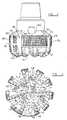
- the drill bitcomprises a bit body 10 and nine blades 12, 14, 16, 18, 20, 22, 24, 26 and 28 formed on the leading face of the bit and extending outwardly from the axis of the bit body towards the gauge region. Between adjacent blades there are defined channels 30, 32, 34, 36, 38, 40, 42, 44 and 46.
- each of the bladesExtending side-by-side along each of the blades are a plurality of cutting structures, indicated at 48.
- the precise nature of the cutting structuresdoes not form a part of the present invention and they may be of any appropriate type.
- theymay comprise circular pre-formed cutting elements brazed to cylindrical carriers which are embedded or otherwise mounted in the blades, the cutting elements each comprising a pre-formed compact having a polycrystalline diamond front cutting layer bonded to a tungsten carbide substrate, the compact being brazed to a cylindrical tungsten carbide carrier.
- the substrate of the pre-formed compactis of sufficient axial length to be mounted directly in the blade, the additional carrier then being omitted.
- Back-up abrasion elements or cuttersmay be spaced rearwardly of some of the cutting structures, as shown.
- Inner nozzles 50, 52, 54are mounted in the surface of the bit body and are located fairly close to the central axis of rotation of the bit. Each inner nozzle is so located that it can deliver drilling fluid to two or more channels.
- peripheral nozzles 56, 58 and 60are located in the channels 34, 40 and 44 respectively and are . orientated to direct drilling fluid inwardly along their respective channels towards the centre of the drill bit. All of the nozzles communicate with a central axial passage (not shown) in the shank of the bit, to which drilling fluid is supplied under pressure downwardly through the drill string in known manner.
- the outer extremities of the bladesare formed with axially extending kickers 62, 64, 66, 68, 70, 72, 74, 76 and 78 respectively, which provide part-cylindrical bearing surfaces which, in use, bear against the surrounding wall of the borehole and stabilise the bit in the borehole.
- Abrasion-resistant bearing elements 80are embedded in the bearing surfaces.
- Each of the channels 32, 34, 36, 38, 40, 42, 44, 46leads to a respective junk slot 80, 82, 84, 86, 88, 90, 92, 94.
- the junk slotsextend upwardly between the kickers, generally parallel to the central longitudinal axis of the drill bit, so that drilling fluid flowing outwardly along each channel passes into the associated junk slot and flows upwardly, between the bit body and the surrounding formation, into the annulus between the drill string and the wall of the borehole.
- the channel 30 between the blades 12 and 14does not lead to a conventional junk slot but continues right up to the gauge region of the drill bit.
- Formed in the channel 30 adjacent the gauge regionis a circular opening 96 into a enclosed cylindrical passage 98 which extends through the bit body to an outlet 100 (see Figure 3) which communicates with the annulus.
- the bearing surfaces 78 and 62 at the outer extremities of the blades 12 and 14are connected by an intermediate bearing surface 102 which extends across the width of the channel 30 so as to form, with the bearing surfaces 78 and 62 a large continuous part-cylindrical bearing surface 104.
- a cylindrical socket 106is formed in the side wall of the passage 98 and is inclined at an angle to the longitudinal axis of the passage.
- a nozzle 108is mounted in the socket 106 and is angled to direct drilling fluid along the passage 98 towards the opening 96, so that the drilling fluid emerges from the opening and flows inwardly along the channel 30.
- the conventional junk slotis replaced by the enclosed passage 98 which passes internally through the bit body.
- Thisenables the provision on the adjacent part of the gauge region of a bearing surface 104 of extended peripheral extent, and this increased bearing surface may enhance the stability of the drill bit in the borehole.
- Figure 4shows diagrammatically a typical pattern of flow of drilling fluid over the face of the bit. It will be seen that drilling fluid flows inwardly, as indicated by the arrows, from the peripheral nozzles 108, 56, 58 and 60 towards the centre of the bit and then across the face of the bit to flow outwardly along other channels, the outward flow being reinforced by the flow from the inner nozzles 50, 52, 54.
- the nozzle 108 in the passage 98may be orientated so as to direct a flow of drilling fluid upwardly through the passage 98 towards the outlet 100, in which case the flow along the channel 30 will be in an outward direction towards the opening 96.
- the nozzle 108may be omitted altogether, and in this case also drilling fluid will flow outwardly along the channel 30, such flow being derived, for example, from the nozzles 50 and 56.
- Figures 1 to 4show an enclosed passage in only one of the channels.
- the inventionincludes within its scope arrangements in which two or more of the channels do not lead to conventional open junk slots but are closed at their outer extremity by a bearing surface in the gauge region, there being provided in each channel an enclosed passage, similar to the passage 98, which passes through the bit body. It will be appreciated that for each channel which is constructed in this manner the overall bearing surface area of the gauge region will be increased. In some cases it may be desirable to replace all the junk slots by enclosed passages similar to the passage 98, in which case the whole of the gauge region of the drill bit will comprise a continuous and uninterrupted 360° bearing surface engaging the wall of the borehole.
- passage 98is described as being a cylindrical passage parallel to the longitudinal axis of the drill bit, other arrangements are possible.
- the passagemay vary in cross-sectional shape and/or diameter along its length. Two or more openings may be provided in the channel, the openings leading to separate passages through the bit body, or two or more openings may lead into a single passage.
- Figure 5shows an alternative arrangement where the opening 110 into the passage 112 is irregularly shaped so as to extend over almost all of the entire area of the channel 30 between the blades 12 and 14.
- a nozzleis not provided in the passage 112 and the flow of drilling fluid along the channel 30 and through the passage 112 is derived from the peripheral nozzle 56, as indicated by the arrows in Figure 5.
Landscapes
- Engineering & Computer Science (AREA)
- Geology (AREA)
- Life Sciences & Earth Sciences (AREA)
- Mining & Mineral Resources (AREA)
- Physics & Mathematics (AREA)
- Environmental & Geological Engineering (AREA)
- Fluid Mechanics (AREA)
- Mechanical Engineering (AREA)
- General Life Sciences & Earth Sciences (AREA)
- Geochemistry & Mineralogy (AREA)
- Chemical & Material Sciences (AREA)
- Crystallography & Structural Chemistry (AREA)
- Earth Drilling (AREA)
Description
- The invention relates to rotary drill bits for use in drilling holes in subsurfaceformations, and of the kind comprising a bit body having a leading face and a gaugeregion, a plurality of blades formed on the leading face of the bit and extendingoutwardly away from the axis of the bit towards the gauge region so as to definebetween the blades a plurality of fluid channels leading towards the gauge region, aplurality of cutting elements mounted along each blade, and a plurality of nozzles in thebit body for supplying drilling fluids to the channels for cleaning and cooling the cuttingelements.
- The invention is particularly, but not exclusively, applicable to drill bits in whichsome or all of the cutters are preform (PDC) cutters each formed, at least in part, frompolycrystalline diamond. One common form of cutter comprises a tablet, usually circularor part circular, made up of a superhard table of polycrystalline diamond, providing thefront cutting face of the element, bonded to a substrate which is usually of cementedtungsten carbide.
- The bit body may be machined from solid metal, usually steel, or may bemoulded using a powder metallurgy process in which tungsten carbide powder isinfiltrated with metal alloy binder inner furnace so as to form a hard matrix.
- In the normal prior art construction the gauge region of the drill bit is formed bya plurality of kickers which are spaced apart around the outer periphery of the bit bodyand are formed with bearing surfaces which, in use, bear against the wall of the borehole. The kickers generally form continuations of the respective blades, and the spaces between the kickers define junk slots with which the channels between the bladescommunicate.. Drilling fluid flowing outwardly along each channel flows into the junkslot at the end of the channel and passes upwardly through the junk slot into the annulusbetween the drill string and the wall of the borehole.
- While such PDC bits have been very successful in drilling relatively softformations, they have been less successful in drilling harder formations, and softformations which include harder or occlusions or stringers. Although good rates ofpenetration are possible in harder formations, the PDC cutters may suffer acceleratedwear and bit life can be too short to be commercially acceptable.
- Studies have suggested that the rapid wear of PDC bits in harder formations maybe due to chipping of the cutters as a result of impact loads caused by vibration of thedrill bit. One of the most harmful types of vibration can be attributed to a phenomenoncalled "bit whirl".
- It is believed that the stability of such a drill bit, and its ability to resist vibration,may be enhanced by increasing the area of the bearing surfaces on the gauge regionwhich engage the wall of the borehole. In the prior art designs, however, the area ofengagement can only be increased by increasing the length and/or width of the bearingsurfaces on the kickers. It may be undesirable to increase the length of the bearingsurfaces since this may lead to difficulties in steering the bit in steerable drilling systems.Similarly, increasing the circumferential width of the bearing surfaces necessarily reducesthe width of the junk slots between the bearing surfaces, and this may lead to less thanoptimum hydraulic flow of drilling fluid along the channels and over the cutters, and may lead to blockage of the junk slots and channels by debris.
- US 4440247 and US 4733735 disclose arrangements in which an enclosedpassage extends between an opening located in a channel between blades of the bitand an outlet which communicates with the annulus between the drill string and thewall of the borehole being drilled. In each case, the opening is located at a radiusadjacent the axis of the bit.
- The present invention provides arrangements whereby the bearing surfacearea of the gauge region of a drill bit of the kind first referred to maybe increasedwithout the above-mentioned disadvantages, and which may also give rise to otheradvantages.
- According to the invention there is provided a rotary drill bit for use indrilling holes in subsurface formations comprising a bit body having a leading faceand a gauge region, a plurality of blades formed on the leading face of the bit andextending outwardly away from the axis of the bit towards the gauge region so asto define between the blades a plurality of fluid channels leading towards the gaugeregion, a plurality of cutting elements mounted along each blade, and a plurality ofnozzles in the bit body for supplying drilling fluid to the channels for cleaning andcooling the cutting elements, wherein there is provided in at least one of saidchannels, at a radial position adjacent the gauge region, an opening into an enclosed passage which passes internally through the bit body to an outlet which, in use,communicates with the annulus between the drill string and the wall of the boreholebeing drilled, the portion of the gauge region outwardly of said opening comprisinga bearing surface which, in use bears against the wall of the borehole and extendsacross the width of said one channel.
- Preferably there is provided in said passage a nozzle for supplying drillingfluid, and said nozzle may be at least partly directed towards said opening so as todeliver drilling fluid through said opening and into and inwardly along said onechannel. Alternatively the nozzle may be at least partly directed towards said outletfrom the passage, so as to deliver drilling fluid through said outlet to the annulus.The nozzle may be mounted in a socket in a wall of said passage, the axis of the socket and of the nozzlebeing inclined with respect to the axis of the passage.
- At least one nozzle for supplying drilling fluid may be so located on the bit bodyas to deliver to said one channel a supply of drilling fluid which flows outwardly alongsaid channel towards the gauge region. The nozzle may be located in said one channel.,for example adjacent the inner end thereof. Alternatively said one channel may be incommunication with another channel defined between blades on the bit body, and afurther nozzle for supplying drilling fluid may be so located on the bit body as to deliverto said other channel a supply of drilling fluid which flows first inwardly along said otherchannel and then outwardly along said one channel towards said opening. The furthernozzle may be located adjacent the outer end of said other channel.
- In any of the above arrangements, each channel on the bit body which is notprovided with an opening into an enclosed passage may lead at its outer extremity to anoutwardly facing junk slot formed in the gauge section and leading to the annulus.
- A plurality of said channels on the bit body may each be formed with an openinginto an enclosed passage which passes internally through the bit body to an outlet which,in use, communicates with the annulus between the drill string and the wall of theborehole being drilled, a portion of the gauge region outwardly of each said openingcomprising a bearing surface which, in use, bears against the wall of the bore hole andextend across the outer extremity of the respective channel.
- In this case, the bearing surfaces at the outer extremities of adjacent channelsformed with said openings are preferably connected to form a substantially continuous bearing surface extending across the combined widths of the adjacent channels.
- All of said channels on the bit body may each be formed with an opening into anenclosed passage which passes internally through the bit body to an outlet which, in use,communicates with the annulus between the drill string and the wall of the bore holebeing drilled, the portions of the gauge region outwardly of said openings comprisinga substantially continuous bearing surface extending around substantially the whole ofthe gauge region.
- In any of the above arrangements at least one of the channels may be providedwith a plurality of openings each of which leads into an enclosed passage which passesinternally through the bit body to an outlet which, in use, communicates with the annulusbetween the drill string and the wall of the borehole being drilled, the portion of thegauge region outwardly of the said openings comprising a bearing surface which, in use,bears against the wall of the bore hole and extends across the width of the channel.
- Each enclosed passage passing internally through the bit body may extendgenerally parallel to the longitudinal central axis of the drill bit.
- The following is a more detailed description of embodiments of the invention,by way of example, reference being made to the accompanying drawings in which:
- Figure 1 is a perspective view of a PDC drill bit in accordance with the presentinvention;
- Figure 2 is an end view of the drill bit shown in Figure 1;
- Figure 3 is a side elevation of the drill bit;
- Figure 4 is a similar view to Figure 2 showing diagrammatically the hydraulic flow over the surface of the drill bit; and
- Figure 5 is a similar view to Figure 2 of an alternative form of drill bit inaccordance with the invention.
- Referring to the drawings: the drill bit comprises a
bit body 10 and nineblades defined channels - Extending side-by-side along each of the blades are a plurality of cuttingstructures, indicated at 48. The precise nature of the cutting structures does not forma part of the present invention and they may be of any appropriate type. For example,as shown, they may comprise circular pre-formed cutting elements brazed to cylindricalcarriers which are embedded or otherwise mounted in the blades, the cutting elementseach comprising a pre-formed compact having a polycrystalline diamond front cuttinglayer bonded to a tungsten carbide substrate, the compact being brazed to a cylindricaltungsten carbide carrier. In another form of cutting structure the substrate of the pre-formedcompact is of sufficient axial length to be mounted directly in the blade, theadditional carrier then being omitted.
- Back-up abrasion elements or cutters may be spaced rearwardly of some of thecutting structures, as shown.
Inner nozzles peripheral nozzles channels 34, 40 and 44 respectively and are. orientated to direct drilling fluid inwardly along their respective channels towards thecentre of the drill bit. All of the nozzles communicate with a central axial passage (notshown) in the shank of the bit, to which drilling fluid is supplied under pressuredownwardly through the drill string in known manner.- The outer extremities of the blades are formed with axially extending
kickers elements 80, of any suitable known form,are embedded in the bearing surfaces. - Each of the
channels respective junk slot - In accordance with the present invention the
channel 30 between theblades channel 30 adjacent the gauge region is acircularopening 96 into a enclosedcylindrical passage 98 which extends through the bit bodyto an outlet 100 (see Figure 3) which communicates with the annulus. - The
bearing surfaces blades surface 102 which extends across the width ofthechannel 30 so as to form, with thebearing surfaces 78 and 62 a large continuouspart-cylindrical bearing surface 104. - As best seen in Figure 1, a cylindrical socket 106 is formed in the side wall of the
passage 98 and is inclined at an angle to the longitudinal axis of the passage. Anozzle 108 is mounted in the socket 106 and is angled to direct drilling fluid along thepassage 98 towards the opening 96, so that the drilling fluid emerges from the opening and flowsinwardly along thechannel 30. - Thus, in the case of the
channel 30, the conventional junk slot is replaced by theenclosedpassage 98 which passes internally through the bit body. This enables theprovision on the adjacent part of the gauge region of abearing surface 104 of extendedperipheral extent, and this increased bearing surface may enhance the stability of the drillbit in the borehole. - Figure 4 shows diagrammatically a typical pattern of flow of drilling fluid overthe face of the bit. It will be seen that drilling fluid flows inwardly, as indicated by thearrows, from the
peripheral nozzles inner nozzles - However, other flow patterns are possible and may be achieved by appropriatelocation and orientation of the nozzles. For example, the
nozzle 108 in thepassage 98may be orientated so as to direct a flow of drilling fluid upwardly through thepassage 98 towards theoutlet 100, in which case the flow along thechannel 30 will be in an outward direction towards the opening 96. Alternatively, thenozzle 108 may be omittedaltogether, and in this case also drilling fluid will flow outwardly along thechannel 30,such flow being derived, for example, from thenozzles - Figures 1 to 4 show an enclosed passage in only one of the channels. However,the invention includes within its scope arrangements in which two or more of thechannels do not lead to conventional open junk slots but are closed at their outerextremity by a bearing surface in the gauge region, there being provided in each channelan enclosed passage, similar to the
passage 98, which passes through the bit body. Itwill be appreciated that for each channel which is constructed in this manner the overallbearing surface area of the gauge region will be increased. In some cases it may bedesirable to replace all the junk slots by enclosed passages similar to thepassage 98, inwhich case the whole of the gauge region of the drill bit will comprise a continuous anduninterrupted 360° bearing surface engaging the wall of the borehole. - Although the
passage 98 is described as being a cylindrical passage parallel tothe longitudinal axis of the drill bit, other arrangements are possible. For example, thepassage may vary in cross-sectional shape and/or diameter along its length. Two ormore openings may be provided in the channel, the openings leading to separatepassages through the bit body, or two or more openings may lead into a single passage. - Figure 5 shows an alternative arrangement where the
opening 110 into thepassage 112 is irregularly shaped so as to extend over almost all of the entire area of thechannel 30 between theblades passage 112 and the flow of drilling fluid along thechannel 30 and through thepassage 112 is derived from theperipheral nozzle 56, as indicated by the arrows in Figure 5.
Claims (15)
- A rotary drill bit for use in drilling holes in subsurface formations comprisinga bit body having a leading face and a gauge region, a plurality of blades (12-28)formed on the leading face of the bit and extending outwardly away from the axisof the bit towards the gauge region so as to define between the blades a plurality offluid channels (30-46) leading towards the gauge region, a plurality of cuttingelements (48) mounted along each blade, and a plurality of nozzles (50-60) in thebit body for supplying drilling fluid to the channels for cleaning and cooling thecutting elements, wherein there is provided in at least one of said channels (30-46)an opening (96) into an enclosed passage (98) which passes internally through thebit body to an outlet (100) which, in use, communicates with the annulus betweenthe drill string and the wall of the borehole being drilled, the portion of the gaugeregion outwardly of said opening (96) comprising a bearing surface (102) which, inuse bears against the wall of the borehole and extends across the width of said oneof the channels (30-46), andcharacterised in that the opening (96) is located at aradial position adjacent the gauge region.
- A drill bit according to Claim 1,characterised in that there is provided in saidpassage (98) a nozzle (108) for supplying drilling fluid, said nozzle being at leastpartly directed towards said opening (96) so as to deliver drilling fluid through said opening and into and inwardly along said one channel (30).
- A drill bit according to Claim 1characterised in that there is provided in saidpassage (98) a nozzle for supplying drilling fluid, said nozzle being at least partlydirectly towards said outlet from the passage, so as to deliver drilling fluid throughsaid outlet to the annulus.
- A drill bit according to Claim 2 or Claim 3,characterised in that said nozzle(108) is mounted in a socket (106) in a wall of said passage (98), the axis of the socketand of the nozzle being inclined with respect to the axis of the passage.
- A drill bit according to any of the preceding claims,characterised in that atleast one nozzle (50) for supplying drilling fluid is so located on the bit body as todeliver to said one channel (30) a supply of drilling fluid which flows outwardly alongsaid channel towards the gauge region.
- A drill bit according to Claim 5,characterised in that said nozzle is locatedin said one channel.
- A drill bit according to Claim 5 or Claim 6,characterised in that said nozzle(50) is located adjacent the inner end of said channel (30).
- A drill bit according to Claim 5,characterised in that said one channel (30)is in communication with another channel (34) defined between blades on the bit body,and a further nozzle (56) for supplying drilling fluid is so located on the bit body as todeliver to said other channel a supply of drilling fluid which flows first inwardly alongsaid other channel (34) and then outwardly along said one channel (30) towards saidopening.
- A drill bit according to Claim 8,characterised in that said further nozzle (56)is located adjacent the outer end of said other channel (34).
- A drill bit according to any of the preceding claims,characterised in thateach channel (32-46) on the bit body which is not provided with an opening into anenclosed passage leads at its outer extremity to an outwardly facing junk slot (80-94) formed in the gauge section and leading to the annulus.
- A drill bit according to any of the preceding claims,characterised in that aplurality of said channels on the bit body are each formed with an opening into anenclosed passage which passes internally through the bit body to an outlet which, in use,communicates with the annulus between the drill string and the wall of the boreholebeing drilled, a portion of the gauge region outwardly of each said opening comprisinga bearing surface which, in use, bears against the wall of the bore hole and extendsacross the outer extremity of the respective channel.
- A drill bit according to Claim 11characterised in that the bearing surfacesat the outer extremities of adjacent channels formed with said openings are connectedto form a substantially continuous bearing surface extending across the combined widthsof the adjacent channel.
- A drill bit according to Claim 12characterised in that all of said channels onthe bit body are each formed with an opening into an enclosed passage which passesinternally through the bit body to an outlet which, in use, communicates with the annulusbetween the drill string and the wall of the bore hole being drilled, the portions of thegauge region outwardly of said openings comprising a substantially continuous bearingsurface extending around substantially the whole of the gauge region.
- A drill bit according to any of the preceding claims,characterised in that atleast one of said channels is provided with a plurality of openings each of which leadsinto an enclosed passage which passes internally through the bit body to an outlet which,in use, communicates with the annulus between the drill string and the wall of the borehole being drilled, the portion of the gauge region outwardly of the said openingscomprising a bearing surface which, in use, bears against the wall of the bore hole andextends across the width of the channel.
- A rotary drill bit according to any of the preceding claims,characterised in that eachenclosed passage (98) passing internally through the bit body extends generally parallelto the longitudinal central axis of the drill bit.
Applications Claiming Priority (4)
| Application Number | Priority Date | Filing Date | Title |
|---|---|---|---|
| GB9420838AGB9420838D0 (en) | 1994-10-15 | 1994-10-15 | Improvements in or relating to rotary drill bits |
| GB9420838 | 1994-10-15 | ||
| GBGB9518267.1AGB9518267D0 (en) | 1994-10-15 | 1995-09-08 | Improvements in or relating to rotary drill bits |
| GB9518267 | 1995-09-08 |
Publications (3)
| Publication Number | Publication Date |
|---|---|
| EP0707132A2 EP0707132A2 (en) | 1996-04-17 |
| EP0707132A3 EP0707132A3 (en) | 1997-04-09 |
| EP0707132B1true EP0707132B1 (en) | 2003-08-06 |
Family
ID=26305817
Family Applications (1)
| Application Number | Title | Priority Date | Filing Date |
|---|---|---|---|
| EP95306937AExpired - LifetimeEP0707132B1 (en) | 1994-10-15 | 1995-09-29 | Rotary drill bit |
Country Status (3)
| Country | Link |
|---|---|
| US (2) | US5671818A (en) |
| EP (1) | EP0707132B1 (en) |
| DE (1) | DE69531431T2 (en) |
Families Citing this family (22)
| Publication number | Priority date | Publication date | Assignee | Title |
|---|---|---|---|---|
| US6089336A (en) | 1995-10-10 | 2000-07-18 | Camco International (Uk) Limited | Rotary drill bits |
| US5904213A (en)* | 1995-10-10 | 1999-05-18 | Camco International (Uk) Limited | Rotary drill bits |
| US5794725A (en)* | 1996-04-12 | 1998-08-18 | Baker Hughes Incorporated | Drill bits with enhanced hydraulic flow characteristics |
| US6164394A (en)* | 1996-09-25 | 2000-12-26 | Smith International, Inc. | Drill bit with rows of cutters mounted to present a serrated cutting edge |
| FR2756002B1 (en)* | 1996-11-20 | 1999-04-02 | Total Sa | BLADE DRILLING TOOL WITH RESERVE SIZES AND CUT-OUT DRAIN CHANNELS |
| US6125947A (en)* | 1997-09-19 | 2000-10-03 | Baker Hughes Incorporated | Earth-boring drill bits with enhanced formation cuttings removal features and methods of drilling |
| GB2339811B (en)* | 1998-07-22 | 2002-05-22 | Camco Internat | Improvements in or relating to rotary drill bits |
| US6427792B1 (en) | 2000-07-06 | 2002-08-06 | Camco International (Uk) Limited | Active gauge cutting structure for earth boring drill bits |
| WO2006089379A1 (en)* | 2005-02-23 | 2006-08-31 | Halliburton Energy Services N.V. | Drill bit with stationary cutting structure |
| US20060234727A1 (en)* | 2005-04-13 | 2006-10-19 | Wirelesswerx International, Inc. | Method and System for Initiating and Handling an Emergency Call |
| US7325631B2 (en)* | 2005-07-29 | 2008-02-05 | Smith International, Inc. | Mill and pump-off sub |
| US20090084607A1 (en)* | 2007-10-01 | 2009-04-02 | Ernst Stephen J | Drill bits and tools for subterranean drilling |
| US20090084606A1 (en)* | 2007-10-01 | 2009-04-02 | Doster Michael L | Drill bits and tools for subterranean drilling |
| US7694755B2 (en)* | 2007-10-15 | 2010-04-13 | Baker Hughes Incorporated | System, method, and apparatus for variable junk slot depth in drill bit body to alleviate balling |
| WO2009058808A1 (en)* | 2007-10-29 | 2009-05-07 | Baker Hughes Incorporated | Drill bits and tools for subterranean drilling |
| WO2009075667A2 (en)* | 2007-11-30 | 2009-06-18 | Halliburton Energy Services | Method and system for predicting performance of a drilling system having multiple cutting structures |
| US9249654B2 (en)* | 2008-10-03 | 2016-02-02 | Halliburton Energy Services, Inc. | Method and system for predicting performance of a drilling system |
| US8079430B2 (en)* | 2009-04-22 | 2011-12-20 | Baker Hughes Incorporated | Drill bits and tools for subterranean drilling, methods of manufacturing such drill bits and tools and methods of off-center drilling |
| US9617794B2 (en) | 2012-06-22 | 2017-04-11 | Smith International, Inc. | Feature to eliminate shale packing/shale evacuation channel |
| CA2886563A1 (en)* | 2012-10-02 | 2014-04-10 | Varel International Ind., L.P. | Flow through gauge for drill bit |
| CN110159202B (en)* | 2018-02-10 | 2024-10-25 | 西南石油大学 | Diamond bit with fixed buffer structure |
| CN109779533A (en)* | 2019-03-29 | 2019-05-21 | 莱州市原野科技有限公司 | PDC drill bit |
Family Cites Families (17)
| Publication number | Priority date | Publication date | Assignee | Title |
|---|---|---|---|---|
| GB713998A (en)* | 1951-11-13 | 1954-08-18 | Reed Roller Bit Co | Improvements in or relating to drill bits |
| US3099324A (en)* | 1959-06-02 | 1963-07-30 | Reed Roller Bit Co | Circulation ports for drill bit |
| US3111179A (en)* | 1960-07-26 | 1963-11-19 | A And B Metal Mfg Company Inc | Jet nozzle |
| GB1348694A (en)* | 1971-05-10 | 1974-03-20 | Shell Int Research | Diamond bit |
| US3951220A (en)* | 1974-08-19 | 1976-04-20 | Vance Industries, Inc. | Archimedes spiral drill bit |
| US4440247A (en)* | 1982-04-29 | 1984-04-03 | Sartor Raymond W | Rotary earth drilling bit |
| CA1217475A (en)* | 1982-09-16 | 1987-02-03 | John D. Barr | Rotary drill bits |
| GB8524146D0 (en)* | 1985-10-01 | 1985-11-06 | Nl Petroleum Prod | Rotary drill bits |
| US4618010A (en)* | 1986-02-18 | 1986-10-21 | Team Engineering And Manufacturing, Inc. | Hole opener |
| US5029657A (en)* | 1989-11-14 | 1991-07-09 | Arthur Mahar | Rock drill bit |
| US5297643A (en)* | 1990-12-19 | 1994-03-29 | Kennametal Inc. | Cold headed center vacuum drill bit |
| US5145017A (en)* | 1991-01-07 | 1992-09-08 | Exxon Production Research Company | Kerf-cutting apparatus for increased drilling rates |
| US5199511A (en)* | 1991-09-16 | 1993-04-06 | Baker-Hughes, Incorporated | Drill bit and method for reducing formation fluid invasion and for improved drilling in plastic formations |
| US5244039A (en)* | 1991-10-31 | 1993-09-14 | Camco Drilling Group Ltd. | Rotary drill bits |
| FI95618C (en)* | 1992-12-03 | 1998-09-03 | Jorma Jaervelae | drilling device |
| GB2277760B (en)* | 1993-05-08 | 1996-05-29 | Camco Drilling Group Ltd | Improvements in or relating to rotary drill bits |
| US5582258A (en)* | 1995-02-28 | 1996-12-10 | Baker Hughes Inc. | Earth boring drill bit with chip breaker |
- 1995
- 1995-09-29DEDE69531431Tpatent/DE69531431T2/ennot_activeExpired - Lifetime
- 1995-09-29EPEP95306937Apatent/EP0707132B1/ennot_activeExpired - Lifetime
- 1995-10-10USUS08/541,774patent/US5671818A/ennot_activeExpired - Lifetime
- 1997
- 1997-04-16USUS08/834,440patent/US5819860A/ennot_activeExpired - Lifetime
Also Published As
| Publication number | Publication date |
|---|---|
| DE69531431D1 (en) | 2003-09-11 |
| US5819860A (en) | 1998-10-13 |
| DE69531431T2 (en) | 2004-07-01 |
| EP0707132A2 (en) | 1996-04-17 |
| US5671818A (en) | 1997-09-30 |
| EP0707132A3 (en) | 1997-04-09 |
Similar Documents
| Publication | Publication Date | Title |
|---|---|---|
| EP0707132B1 (en) | Rotary drill bit | |
| EP0884449B1 (en) | Rotary drill bits | |
| US6089336A (en) | Rotary drill bits | |
| EP0872624B1 (en) | Improvements in or relating to rotary drill bits | |
| US6062325A (en) | Rotary drill bits | |
| US6129161A (en) | Rotary drill bits with extended bearing surfaces | |
| EP1096103B1 (en) | Drill-out bi-center bit | |
| US5755297A (en) | Rotary cone drill bit with integral stabilizers | |
| EP0710765B1 (en) | Improvements relating to rotary drill bits | |
| US7059430B2 (en) | Hydro-lifter rock bit with PDC inserts | |
| US6021858A (en) | Drill bit having trapezium-shaped blades | |
| EP0624708B1 (en) | Nozzle arrangement for drag type drill bit | |
| US7299887B2 (en) | Roller bit with a journal pin offset from the central axis thereof | |
| US4697654A (en) | Rotary drill bits | |
| GB2294070A (en) | Rotary drill bit with enclosed fluid passage | |
| GB2361496A (en) | Placement of primary and secondary cutters on rotary drill bit | |
| EP1270868B1 (en) | A bi-centre bit for drilling out through a casing shoe | |
| GB2359838A (en) | Rotary drill bit | |
| GB2402688A (en) | Rolling cone drill bit |
Legal Events
| Date | Code | Title | Description |
|---|---|---|---|
| PUAI | Public reference made under article 153(3) epc to a published international application that has entered the european phase | Free format text:ORIGINAL CODE: 0009012 | |
| AK | Designated contracting states | Kind code of ref document:A2 Designated state(s):BE DE | |
| PUAL | Search report despatched | Free format text:ORIGINAL CODE: 0009013 | |
| AK | Designated contracting states | Kind code of ref document:A3 Designated state(s):BE DE | |
| 17P | Request for examination filed | Effective date:19970930 | |
| 17Q | First examination report despatched | Effective date:20020711 | |
| GRAH | Despatch of communication of intention to grant a patent | Free format text:ORIGINAL CODE: EPIDOS IGRA | |
| GRAH | Despatch of communication of intention to grant a patent | Free format text:ORIGINAL CODE: EPIDOS IGRA | |
| GRAA | (expected) grant | Free format text:ORIGINAL CODE: 0009210 | |
| AK | Designated contracting states | Designated state(s):BE DE | |
| REF | Corresponds to: | Ref document number:69531431 Country of ref document:DE Date of ref document:20030911 Kind code of ref document:P | |
| PLBE | No opposition filed within time limit | Free format text:ORIGINAL CODE: 0009261 | |
| STAA | Information on the status of an ep patent application or granted ep patent | Free format text:STATUS: NO OPPOSITION FILED WITHIN TIME LIMIT | |
| 26N | No opposition filed | Effective date:20040507 | |
| PGFP | Annual fee paid to national office [announced via postgrant information from national office to epo] | Ref country code:BE Payment date:20051123 Year of fee payment:11 | |
| PG25 | Lapsed in a contracting state [announced via postgrant information from national office to epo] | Ref country code:BE Free format text:LAPSE BECAUSE OF NON-PAYMENT OF DUE FEES Effective date:20060930 | |
| BERE | Be: lapsed | Owner name:*CAMCO DRILLING GROUP LTD Effective date:20060930 | |
| PGFP | Annual fee paid to national office [announced via postgrant information from national office to epo] | Ref country code:DE Payment date:20140923 Year of fee payment:20 | |
| REG | Reference to a national code | Ref country code:DE Ref legal event code:R071 Ref document number:69531431 Country of ref document:DE |