EP0704308A1 - Printhead for an ink jet printer and device for refilling such a printhead - Google Patents
Printhead for an ink jet printer and device for refilling such a printheadDownload PDFInfo
- Publication number
- EP0704308A1 EP0704308A1EP95113526AEP95113526AEP0704308A1EP 0704308 A1EP0704308 A1EP 0704308A1EP 95113526 AEP95113526 AEP 95113526AEP 95113526 AEP95113526 AEP 95113526AEP 0704308 A1EP0704308 A1EP 0704308A1
- Authority
- EP
- European Patent Office
- Prior art keywords
- printhead
- membrane
- cannula
- ink supply
- ventilation
- Prior art date
- Legal status (The legal status is an assumption and is not a legal conclusion. Google has not performed a legal analysis and makes no representation as to the accuracy of the status listed.)
- Withdrawn
Links
- 239000012528membraneSubstances0.000claimsabstractdescription54
- 238000005192partitionMethods0.000claimsabstractdescription8
- 238000009423ventilationMethods0.000claimsdescription43
- 238000007789sealingMethods0.000claimsdescription40
- 238000005429filling processMethods0.000claimsdescription18
- 239000000463materialSubstances0.000claimsdescription10
- 241001631457CannulaSpecies0.000claimsdescription8
- 239000004952PolyamideSubstances0.000claimsdescription7
- 229920002647polyamidePolymers0.000claimsdescription7
- 229920000642polymerPolymers0.000claimsdescription7
- 229920001343polytetrafluoroethylenePolymers0.000claimsdescription6
- 239000004810polytetrafluoroethyleneSubstances0.000claimsdescription6
- 229910010293ceramic materialInorganic materials0.000claimsdescription5
- -1polytetrafluoroethylenePolymers0.000claimsdescription5
- 239000007788liquidSubstances0.000abstractdescription2
- 238000000638solvent extractionMethods0.000abstract1
- 230000000694effectsEffects0.000description4
- 230000008901benefitEffects0.000description3
- 238000000034methodMethods0.000description3
- 230000008569processEffects0.000description3
- 238000006243chemical reactionMethods0.000description2
- 230000001419dependent effectEffects0.000description2
- 238000004519manufacturing processMethods0.000description2
- 239000003566sealing materialSubstances0.000description2
- 239000004698PolyethyleneSubstances0.000description1
- 238000010521absorption reactionMethods0.000description1
- 230000009471actionEffects0.000description1
- 230000008859changeEffects0.000description1
- 239000003086colorantSubstances0.000description1
- 238000010276constructionMethods0.000description1
- 238000011109contaminationMethods0.000description1
- 238000010586diagramMethods0.000description1
- 239000011888foilSubstances0.000description1
- 230000002706hydrostatic effectEffects0.000description1
- 238000003780insertionMethods0.000description1
- 230000037431insertionEffects0.000description1
- 230000007935neutral effectEffects0.000description1
- 230000000149penetrating effectEffects0.000description1
- 230000035515penetrationEffects0.000description1
- 230000002093peripheral effectEffects0.000description1
- 229920000573polyethylenePolymers0.000description1
- 238000001228spectrumMethods0.000description1
- 230000007704transitionEffects0.000description1
Images


Classifications
- B—PERFORMING OPERATIONS; TRANSPORTING
- B41—PRINTING; LINING MACHINES; TYPEWRITERS; STAMPS
- B41J—TYPEWRITERS; SELECTIVE PRINTING MECHANISMS, i.e. MECHANISMS PRINTING OTHERWISE THAN FROM A FORME; CORRECTION OF TYPOGRAPHICAL ERRORS
- B41J2/00—Typewriters or selective printing mechanisms characterised by the printing or marking process for which they are designed
- B41J2/005—Typewriters or selective printing mechanisms characterised by the printing or marking process for which they are designed characterised by bringing liquid or particles selectively into contact with a printing material
- B41J2/01—Ink jet
- B41J2/17—Ink jet characterised by ink handling
- B41J2/175—Ink supply systems ; Circuit parts therefor
- B41J2/17503—Ink cartridges
- B41J2/17513—Inner structure
- B—PERFORMING OPERATIONS; TRANSPORTING
- B41—PRINTING; LINING MACHINES; TYPEWRITERS; STAMPS
- B41J—TYPEWRITERS; SELECTIVE PRINTING MECHANISMS, i.e. MECHANISMS PRINTING OTHERWISE THAN FROM A FORME; CORRECTION OF TYPOGRAPHICAL ERRORS
- B41J2/00—Typewriters or selective printing mechanisms characterised by the printing or marking process for which they are designed
- B41J2/005—Typewriters or selective printing mechanisms characterised by the printing or marking process for which they are designed characterised by bringing liquid or particles selectively into contact with a printing material
- B41J2/01—Ink jet
- B41J2/17—Ink jet characterised by ink handling
- B41J2/175—Ink supply systems ; Circuit parts therefor
- B41J2/17503—Ink cartridges
- B41J2/17506—Refilling of the cartridge
Definitions
- FIG. 2shows a printhead 1 in the form of a multicolor printhead.
- three ink supply spaces 12are formed which contain the color components magenta, cyan and yellow.
- two continuous partitions 16are mounted in the housing 10, which are designed in the manner described above.
- At the bottom of the housing 10there is an ink channel 28, which connects the ink spaces 12 and produces (not shown) nozzle plate.
Landscapes
- Ink Jet (AREA)
Abstract
Description
Translated fromGermanDie Erfindung betrifft einen Druckkopf für einen Tintenstrahldrucker gemäß Oberbegriff des Anspruchs 1, sowie eine Vorrichtung zum Wiederbefüllen eines derartigen Druckkopfs gemäß Oberbegriff des Anspruchs 11.The invention relates to a printhead for an inkjet printer according to the preamble of
Derartige Druckköpfe finden insbesondere in jüngster Zeit eine immer stärkere Verbreitung, da sie wiederbefüllbar gestaltet und damit mehrfach wiederverwendbar sind. Hinsichtlich ihres grundsätzlichen Aufbaus sind sie funktionsbedingt und aus Kompatibilitätsgründen vergleichbar zu den gängigen Einweg-Druckköpfen, die nach wie vor in großer Zahl entweder als Erstausrüstung in Tintenstrahldruckern eingebaut werden oder als Ersatzdruckköpfe im Handel erhältlich sind.Such printheads have become increasingly widespread, particularly in recent times, since they are designed to be refillable and are therefore reusable several times. With regard to their basic structure, they are function-related and, for reasons of compatibility, comparable to the common disposable printheads, which are still in large numbers either installed as original equipment in inkjet printers or are commercially available as replacement printheads.
Diese Druckköpfe besitzen im einfachsten Fall einen einzelnen Tintenvorratsraum, der im Inneren eines Gehäuses angeordnet ist. Der Tintenvorratsraum ist in der Regel mit einem die Tinte aufnehmenden, porösen oder schwammartigen Körper gefüllt, in welchem der Tintenvorrat aufgenommen ist. Auch sind vergleichbar aufgebaute Mehrfarben-Druckköpfe erhältlich, bei denen innerhalb des Gehäuses mehrere, voneinander getrennte Tintenvorratsräume vorgesehen sind. Üblicherweise sind drei solcher Tintenvorratsräume vorhanden, die drei unterschiedlichen Farbkomponenten, z.B. Magenta, Cyan und Gelb beinhalten, mit denen sich das gesamte Farbspektrum darstellen läßt. Auch gibt es Ausführungsvarianten von Druckköpfen, die einen zusätzlichen Tintenvorratsraum für schwarze Tinte besitzen.In the simplest case, these printheads have a single ink supply space, which is arranged inside a housing. The ink supply space is usually filled with a porous or sponge-like body which receives the ink and in which the ink supply is accommodated. Comparably constructed multi-color printheads are also available, in which several separate ink supply spaces are provided within the housing. Typically, there are three such ink reservoirs that contain three different color components, e.g. Contain magenta, cyan and yellow, with which the entire color spectrum can be represented. There are also design variants of printheads that have an additional ink supply space for black ink.
Die Tintenvorratsräume sind teilweise über eine Öffnung von außen her zugänglich. Ursprünglich waren diese Öffnungen vorgesehen, um die Tintenvorratsräume zu belüften und damit das Abfließen von Tinte zu ermöglichen. Dieser Effekt ist beispielsweise in der EP 0 381 363 A2 am Beispiel eines Einfarben-Druckkopfs erläutert.The ink supply rooms are partially accessible from the outside through an opening. These openings were originally intended to ventilate the ink supply spaces and thus allow ink to flow away. This effect is explained, for example, in EP 0 381 363 A2 using the example of a single-color print head.
Derartige Öffnungen können aber auch genutzt werden, um Tinte mittels geeigneter Vorrichtungen, beispielsweise mit Hilfe einer handspritzenähnlichen und mit einer Kanüle versehenen Pumpe gezielt nachzufüllen. Aus der DE 42 35 029 C2 ist dies anhand eines Mehrfach-Druckkopfs erläutert, wobei die dort gezeigten Öffnungen als Befüllbohrungen einer das Gehäuse - und damit die Tintenvorratsräume - verschließenden Abdeckplatte ausgeführt sind. Zum Wiederbefüllen wird der Druckkopf aus dem Tintenstrahldrucker entfernt und beispielsweise von Hand mittels der o.e. handspritzenähnlichen Pumpen wiederbefüllt.However, such openings can also be used to refill ink in a targeted manner by means of suitable devices, for example with the aid of a pump similar to a hand syringe and provided with a cannula. This is explained in DE 42 35 029 C2 using a multiple printhead, the openings shown there being designed as filling bores in a cover plate which closes the housing and thus the ink supply spaces. For refilling, the printhead is removed from the inkjet printer and refilled, for example, by hand using the pumps similar to hand syringes.
Von einem derartigen Druckkopf, wie er in dem genannten Dokument beschrieben ist, geht die Erfindung aus. Obwohl sich insbesondere mit zusätzlicher Unterstützung des in dem letztgenannten Dokument weiterhin beschriebenen Deckels diese Druckköpfe mit relativ geringem Aufwand wiederbefüllen lassen, treten in der praktischen Handhabung häufig Probleme auf. So findet sich in der genannten DE 42 35 029 C2 bereits der Hinweis, daß besondere Maßnahmen getroffen werden sollten, um ein Überfüllen des Druckkopfs zu vermeiden. Zum einen ist dies unter ökonomischem Aspekt unerwünscht, da an sich nur der konkrete Ersatzbedarf an Tintenvorrat ergänzt zu werden braucht, und andererseits die überschießende Tinte ein großes Verschmutzungspotential darstellt. Dies betrifft nicht nur die Bedienperson, sondern auch den Druckkopf selbst. Beim Mehrfarben-Druckkopf besteht darüber hinaus allerhöchste Gefahr, daß die aus der Befüllbohrung überschießende Tinte in eine oder mehrere benachbarte Tintenvorratsräume über die entsprechenden Befüllbohrungen eindringt und damit die jeweilige Farbkomponente verfälscht wird. Ein derartiger Druckkopf ist damit an sich unbrauchbar geworden, da eine farbkorrekte Wiedergabe nicht mehr möglich ist. Der Nachfüllvorgang erfordert somit allerhöchste Aufmerksamkeit, wobei bereits kleinere Unachtsamkeiten dazu führen können, daß der Mehrfarben-Druckkopf nicht mehr verwendet werden kann.The invention is based on such a printhead as described in the cited document. Although these printheads can be refilled with relatively little effort, in particular with additional support from the lid, which is also described in the last-mentioned document, problems often arise in practical handling. For example, DE 42 35 029 C2 already mentions that special measures should be taken to avoid overfilling the print head. On the one hand, this is undesirable from an economic point of view, since in itself only the concrete replacement need for ink supply needs to be supplemented, and on the other hand, the excess ink represents a great potential for contamination. This applies not only to the operator, but also to the printhead itself. In the multicolor printhead, there is also the greatest risk that the ink that overshoots from the filling hole will penetrate into one or more adjacent ink supply spaces via the corresponding filling holes and thus falsify the respective color component. A printhead of this type has thus become unusable per se since it is no longer possible to reproduce the color correctly. The refill process therefore requires the utmost attention, even minor inattentions can lead to the fact that the multicolor print head can no longer be used.
Das Problem des Überfüllens tritt weiterhin bei der Verwendung von Befüllstationen auf, wie sie beispielsweise in der vorangemeldeten, jedoch nachveröffentlichten DE 43 27 178 .. (deutsche Patentanmeldung P 43 27 178) beschrieben sind. Diese Vorrichtungen bestehen aus einer Halterung mit einem Dichtungsorgan, in die der zu befüllende Druckkopf eingesetzt und verrastet wird. Hierdurch wird die an der Unterseite des Druckkopfs befindliche Düsenplatte sowie eine gegebenenfalls vorhandene Belüftungsöffnung dichtend zur Anlage an das Dichtungsorgan gebracht. Anschließend wird auf den eingesetzten Druckkopf bzw. die Halterung ein mit einer Kanüle versehener Kanülenträger aufgesetzt, so daß die Kanüle über die Befüllbohrung des Druckkopfs in den Tintenvorratsraum hineingeführt wird. Auf die Kanüle und gegebenenfalls durch eine korrespondierende Ausnehmung im Kanülenträger geführt, wird eine Nachfüllpatrone aufgesteckt und eine die Nachfüllpatrone verschließende Kappe entfernt. Nunmehr läuft der Befüllvorgang ohne weiteres Zutun selbsttätig ab, wobei ein unbeabsichtigtes Austreten von Tinte aus diversen Öffnungen, wie beispielsweise der Düsenplatte oder den Belüftungsöffnungen durch die Dichtungsorgane verhindert wird.The problem of overfilling also occurs when filling stations are used, as described, for example, in the previously reported but subsequently published DE 43 27 178 .. (German patent application P 43 27 178). These devices consist of a holder with a sealing member into which the printhead to be filled is inserted and locked. As a result, the nozzle plate located on the underside of the print head and a any existing ventilation opening sealingly brought into contact with the sealing member. A cannula holder provided with a cannula is then placed on the printhead or the holder used, so that the cannula is introduced into the ink supply space via the filling bore of the printhead. A refill cartridge is placed on the cannula and, if necessary, through a corresponding recess in the cannula holder, and a cap closing the refill cartridge is removed. The filling process now runs automatically without any further action, and inadvertent leakage of ink from various openings, such as, for example, the nozzle plate or the ventilation openings, is prevented by the sealing members.
Obwohl damit ein weitgehend problemloses Wiederbefüllen von Druckköpfen möglich ist, besteht dennoch unter bestimmten Umständen die Gefahr, daß Tinte unerwünscht austritt. So durchsetzt die Kanüle die Befüllbohrung zumindest mit geringem radialen Spiel, wodurch ein Spalt verbleibt, durch den die von der einfließenden Tinte verdrängte Luft entweichen kann. Durch diesen Spalt kann somit Tinte austreten, sofern mehr Tinte zugeführt wird als der Tintenvorratsraum aufnehmen kann.Although this enables a largely problem-free refilling of printheads, there is nevertheless a risk under certain circumstances that ink will escape undesirably. The cannula thus penetrates the filling bore at least with a slight radial play, which leaves a gap through which the air displaced by the inflowing ink can escape. Ink can thus escape through this gap if more ink is supplied than the ink supply space can accommodate.
Eine derartige Situation ergibt sich dann, wenn der Druckkopf nicht vollständig leergeschrieben ist, sich somit noch Tinte im Tintenvorratsraum befindet und damit das Aufnahmevolumen geringer ist als der Inhalt der Nachfüllpatrone.Such a situation arises when the print head is not completely empty, so there is still ink in the ink supply space and the volume of the receptacle is therefore less than the content of the refill cartridge.
Im Falle des Einfarben-Druckkopfs ist diese Schwierigkeit an sich problemlos beherrschbar, sofern dafür Sorge getragen wird, daß vor dem Wiederbefüllen der Druckkopf vollständig leergeschrieben wird. Weitaus schwieriger stellt sich das Problem bei einem Mehrfarben-Druckkopf dar, der mit einer vergleichbaren, für das Wiederbefüllen eines Mehrfarben-Druckkopfs bestimmten Vorrichtung wiederbefüllt werden soll. Bei einem Mehrfarben-Druckkopf tritt der hinlänglich bekannte Effekt ein, daß der individuelle Verbrauch der einzelnen Farbkomponenten variiert, so daß zumeist lediglich eine der Farbkomponenten erschöpft ist, wohingegen der Vorrat an übrigen Farbkomponenten noch nicht erschöpft ist. Für eine farbkorrekte Wiedergabe ist es deshalb erforderlich, bereits in diesem Stadium Tinte nachzufüllen. Aus praktischen Gründen wird hierbei nicht nur diejenige Farbkomponente ergänzt, deren Vorrat erschöpft ist, vielmehr werden bei dieser Gelegenheit auch die Tintenvorratskammern der übrigen Farbkomponenten aufgefüllt. In diesem Zusammenhang ist sofort erkennbar, daß das Ergänzen derjenigen Farbkomponenten, von denen sich noch nennenswerte Reste in den Tintenvorratskammern befinden, zu Problemen führt. Da das Volumen der entsprechenden Nachfüllpatronen für diese Farbkomponenten zu groß ist, muß der an sich selbsttätig ablaufende Befüllvorgang ständig beobachtet und individuell für jede der Farbkomponenten vorzeitig, d.h. vor dem vollständigen Leerlaufen der Nachfüllpatrone, gestoppt werden. Dies ist prinzipiell unerwünscht und zudem in vielen Fällen kaum praktikabel, da häufig die Tintenvorratskammern - und damit der Füllstand - nicht oder nur mit großer Mühe einsehbar sind. Ein unbeabsichtigtes Überfüllen einzelner Tintenvorratskammern läßt sich trotz der gebotenen Umsicht häufig nicht vermeiden.In the case of the single-color printhead, this difficulty can easily be mastered as long as care is taken to ensure that the printhead is completely rewritten before refilling. This is much more difficult Problem with a multi-color printhead, which is to be refilled with a comparable device intended for refilling a multicolor printhead. In the case of a multicolor print head, there is the well-known effect that the individual consumption of the individual color components varies, so that mostly only one of the color components is exhausted, whereas the supply of other color components is not yet exhausted. For correct color reproduction, it is therefore necessary to refill ink at this stage. For practical reasons, not only the color component whose supply is exhausted is supplemented, but the ink supply chambers of the other color components are also filled on this occasion. In this context it is immediately apparent that the addition of those color components, of which there are still significant residues in the ink supply chambers, leads to problems. Since the volume of the corresponding refill cartridges is too large for these color components, the self-filling process must be constantly monitored and stopped individually for each of the color components, ie before the refill cartridge is completely empty. In principle, this is undesirable and, in many cases, hardly practical, since the ink supply chambers - and thus the fill level - are often difficult or impossible to see. Inadvertent overfilling of individual ink supply chambers can often not be avoided despite the necessary care.
Der Erfindung lag daher das Problem zugrunde, einen Druckkopf der eingangs genannten Art derart weiterzuentwickeln, daß dessen Tintenvorratskammer bzw. -vorratskammern nicht überfüllt werden können. Insbesondere soll im Falle des Mehrfarben-Druckkopfs ein Übertreten überschießender Tinte in eine benachbarte Tintenvorratskammer ausgeschlossen werden, so daß sich nunmehr auch Mehrfarben-Druckköpfe ohne besondere Vorsichtsmaßnahmen wiederbefüllen lassen.The invention was therefore based on the problem of developing a print head of the type mentioned at the outset in such a way that its ink supply chamber or supply chambers cannot be overfilled. In particular, in the case of the multicolor printhead, excess ink should be prevented from passing into an adjacent ink supply chamber are so that now multi-color printheads can be refilled without special precautions.
Der Erfindung lag weiterhin das Problem zugrunde, eine Befüllstation zur Verfügung zu stellen, mit der ein solchermaßen gestalteter Druckkopf problemlos wiederbefüllbar ist, ohne daß die Bedienperson den Befüllvorgang beaufsichtigen und bei Erreichen eines bestimmten Füllstands eingreifen muß, um ein Überfließen von Tinte zu vermeiden.The invention was also based on the problem of providing a filling station with which a printhead designed in this way can be refilled without problems, without the operator having to supervise the filling process and intervene when a certain fill level is reached, in order to avoid ink overflow.
Das Problem wird mit einem Druckkopf gelöst, der die Merkmale des Anspruchs 1 aufweist.The problem is solved with a printhead having the features of
Vorteilhafte Ausführungsformen der Erfindung sind durch die Merkmale der nachgeordneten abhängigen Ansprüche angegeben.Advantageous embodiments of the invention are specified by the features of the subordinate dependent claims.
Das Problem wird weiterhin mit einer Vorrichtung gelöst, die die Merkmale des Anspruchs 11 aufweist.The problem is further solved with a device having the features of claim 11.
Vorteilhafte Varianten sind durch die Merkmale der hiervon abhängigen Ansprüche definiert.Advantageous variants are defined by the features of the claims dependent thereon.
Die Erfindung basiert auf der Idee, ein Belüftungsventil in Form einer Membran vorzusehen, die einerseits die durch die einfließende Tinte verdrängte Luft nach außen hin entweichen läßt, andererseits jedoch flüssigkeitsdicht ist und damit ein Austreten von Tinte an dieser Stelle zuverlässig verhindert.The invention is based on the idea of providing a ventilation valve in the form of a membrane which on the one hand allows the air displaced by the inflowing ink to escape to the outside, but on the other hand is liquid-tight and thus reliably prevents ink from escaping at this point.
Dieser Effekt kann auf verschiedene Art und Weise benutzt werden, um je nach konkreter Ausgestaltung des Druckkopfs und/oder der Befüllstation ein Überfüllen sicher zu vermeiden. Als gemeinsame Vorraussetzung ist in allen Fällen die Rahmenbedingung zu beachten, daß alle übrigen Öffnungen, Spalte oder dergleichen, durch die Luft entweichen könnte, während des Befüllens dicht verschlossen gehalten werden. Dies betrifft insbesondere auch den Bereich der Tintenvorratskammer, durch den die Tinte zugeführt wird und in den meisten Fällen als spezielle Befüllbohrung gestaltet sein kann, die von der Kanüle durchsetzt wird. Weiterhin sind häufig auch Spalten, Ritzen oder dergleichen vorhanden, die teils beabsichtigt, teils fertigungsbedingt, beispielsweise zwischen Gehäuse und Gehäusedeckel, auftreten.This effect can be used in various ways to reliably avoid overfilling, depending on the specific design of the print head and / or the filling station. As a common requirement, the general condition must be observed in all cases that all other openings, Gaps or the like, through which air could escape, are kept tightly closed during filling. This also applies in particular to the area of the ink supply chamber through which the ink is supplied and in most cases can be designed as a special filling hole through which the cannula passes. Furthermore, there are often also gaps, crevices or the like, some of which are intended, some of which are production-related, for example between the housing and the housing cover.
In allen diesen Fällen muß durch eine spezielle und/oder nachträgliche Abdichtung dafür Sorge getragen werden, daß die während des Befüllvorgangs entweichende Luft ausschließlich durch die als Belüftungsventil wirkende Membran austreten kann. Sobald die einfließende Tinte den Tintenvorratsraum vollständig ausgefüllt und die gesamte darin befindliche Luft verdrängt hat, wird ein weiterer Zufluß von Tinte unterbunden, da die Tinte zwar an der Membran ansteht, diese aber nicht durchdringen kann. Die Membran muß hierbei so konzipiert sein, daß sie dem Druck, mit dem die Tinte zugeführt wird (beispielsweise dem hydrostatischen Druck), stand hält.In all these cases, special and / or subsequent sealing must be used to ensure that the air escaping during the filling process can only escape through the membrane, which acts as a ventilation valve. As soon as the inflowing ink has completely filled the ink supply space and displaced all the air inside, a further inflow of ink is prevented, since the ink is present on the membrane but cannot penetrate it. The membrane must be designed so that it withstands the pressure at which the ink is supplied (for example, the hydrostatic pressure).
Im Falle des Befüllens mit Hilfe der eingangs beschriebenen Befüllstation bedeutet dies, daß nunmehr der Befüllvorgang völlig unbeaufsichtigt ablaufen kann, da das Ausfließen der Tinte aus der Nachfüllpatrone selbstätig gestoppt wird, sobald der betreffende Tintenvorratsraum vollständig aufgefüllt ist. Die aufgesetzte Nachfüllpatrone kann mit der Kappe verschlossen und anschließend vom Kanülenträger abgezogen werden und steht für einen weiteren Befüllvorgang erneut zur Verfügung. Auch ist es möglich, Nachfüllpatronen mit einem sehr viel größeren Tintenvorrat zu verwenden, welche für mehrfache Nachfüllvorgänge geeignet sind.In the case of filling with the aid of the filling station described at the outset, this means that the filling process can now proceed completely unattended, since the outflow of the ink from the refill cartridge is automatically stopped as soon as the relevant ink supply space is completely filled. The attached refill cartridge can be closed with the cap and then removed from the cannula holder and is available again for a further filling process. It is also possible to use refill cartridges with a much larger ink supply, which are suitable for multiple refill processes.
Die konkrete Umsetzung dieser Idee kann an sich beliebig erfolgen. Eine besonders einfache Möglichkeit eröffnet sich bei Druckköpfen, bei denen die Tintenvorratsräume durch eine auf das Gehäuse aufgesetzte Zwischenplatte abgedeckt sind, wobei die Zwischenplatte für jede Tintenvorratskammer eine Befüllbohrung aufweist. In diesem Fall kann das Belüftungsventil einfach dadurch realisiert werden, daß beispielsweise neben jeder Befüllbohrung eine weitere Bohrung als Belüftungsbohrung angebracht ist, die mit der Membran verschlossen ist. Ein besonders einfacher konstruktiver Aufbau ergibt sich, sofern als Membran ein Stopfen bzw. ein zylindrischer Körper verwendet wird, welcher in die Belüftungsbohrung eingesetzt ist.The concrete implementation of this idea can be done in any way. A particularly simple possibility opens up for printheads in which the ink supply spaces are covered by an intermediate plate placed on the housing, the intermediate plate having a filling hole for each ink supply chamber. In this case, the ventilation valve can be realized simply in that, for example, in addition to each filling hole, a further hole is made as a ventilation hole, which is closed with the membrane. A particularly simple structural design is obtained if a stopper or a cylindrical body is used as the membrane, which is inserted into the ventilation hole.
Zur Abdichtung der Befüllbohrungen kann entweder die einzuführende Kanüle oder aber die Befüllbohrungen selbst mit Dichtungsorganen versehen sein, so daß eine Abdichtung zwischen der Kanüle und der Befüllbohrung erreicht wird. Die Variante, bei der das Dichtungsorgan jeweils unmittelbar an der Befüllbohrung angebracht ist, erlaubt weiterhin die Verwendung der handspritzenähnlichen Pumpen, wohingegen die Version ohne derartige Dichtungsorgane an der Befüllbohrung geeignete Maßnahmen an der Kanüle erfordert und deshalb für die Anwendung im Zusammenhang mit einer entsprechend gestalteten Befüllstation prädestiniert ist.To seal the filling holes, either the cannula to be inserted or the filling holes themselves can be provided with sealing elements, so that a seal between the cannula and the filling hole is achieved. The variant, in which the sealing member is attached directly to the filling hole, still allows the use of hand-syringe-like pumps, whereas the version without such sealing members on the filling hole requires suitable measures on the cannula and therefore for use in connection with an appropriately designed filling station is predestined.
Weiterhin kann ein zumindest teilweise erhaben geformter Deckel auf die Zwischenplatte und/oder das Gehäuse aufgesetzt sein, welcher Durchtrittsöffnungen trägt, die den Befüllbohrungen jeweils eindeutig zugeordnet sind. Es ist dies ein Deckel, wie er eingangs beschrieben ist. Insoweit können die bislang noch weit verbreiteten Einweg-Druckköpfe ohne Funktionseinbuße problemlos zu wiederbefüllbaren Druckköpfen umgerüstet werden, wobei gleichzeitig die Membran als Überfüllschutz integrierbar ist. Hierdurch wird ein auf diese Weise umgerüsteter Druckkopf ohne Einschränkung auch für die Verwendung in einer Befüllstation tauglich.Furthermore, an at least partially raised-shaped lid can be placed on the intermediate plate and / or the housing, which carries through openings which are clearly assigned to the filling bores. It is a lid as described at the beginning. In this respect, the previously widely used disposable printheads can easily be refilled printheads without loss of function be converted, while the membrane can be integrated as overfill protection. As a result, a printhead converted in this way is also suitable for use in a filling station without restriction.
Auf das Anbringen von Zusatzbohrungen als Belüftungsbohrungen kann verzichtet werden, sofern eine flächige Membran anstelle der Zwischenplatte auf das Gehäuse aufgesetzt wird. Dabei muß die Membran dicht sowohl mit dem Gehäuserand als auch mit den Stirnseiten von Trennwänden verbunden sein, welche im Inneren des Gehäuses als Kammerwände zur Unterteilung in separate Tintenvorratsräume bzw. -kammern angebracht sind. Um weiterhin eine Zugänglichkeit zu den einzelnen Tintenvorratskammern zu gewährleisten, müssen entsprechende Befüllöffnungen unmittelbar in der Membran angebracht werden. Es ist erforderlich, daß die Membran eine ausreichende Festigkeit bzw. Stabilität aufweist, damit weiterhin eine sichere Abdichtung zwischen der Kanüle und der Befüllöffnung erreicht werden kann.It is not necessary to make additional holes as ventilation holes if a flat membrane is placed on the housing instead of the intermediate plate. The membrane must be tightly connected both to the housing edge and to the end faces of partition walls, which are attached in the interior of the housing as chamber walls for subdivision into separate ink supply rooms or chambers. In order to continue to ensure access to the individual ink supply chambers, appropriate filling openings must be made directly in the membrane. It is necessary that the membrane has sufficient strength or stability so that a secure seal between the cannula and the filling opening can still be achieved.
Eine besonders elegante und zweckmäßige Variante ergibt sich, wenn die Membran aus einem selbstverschließenden Folienmaterial besteht, wobei die Membran wiederum vollflächig das Gehäuse abdeckt und am Gehäuserand und an den Stirnseiten der Kammerwände verschweißt oder verklebt ist. In diesem Fall kann auf Befüllbohrungen oder -öffnungen sowie auf spezielle Dichtungsorgane vollständig verzichtet werden, da die Kanüle beim Einstechen und Durchdringen der Membran von dem verdrängten Material dichtend umschlossen wird, so daß ein Austreten von Tinte bei eingestochener Kanüle verhindert wird. Nach Beendigung des Befüllvorgangs kann die Kanüle aus der Membran herausgezogen werden, wobei das verdrängte Material in seine Ausgangsposition zurückweicht und die Einstichstelle wieder dicht verschließt.A particularly elegant and practical variant results if the membrane consists of a self-sealing film material, the membrane in turn covering the entire surface of the housing and being welded or glued to the housing edge and to the end faces of the chamber walls. In this case, filling holes or openings as well as special sealing elements can be completely dispensed with, since the cannula is sealed by the displaced material when piercing and penetrating the membrane, so that ink cannot escape when the cannula is pierced. After the filling process has been completed, the cannula can be pulled out of the membrane, the displaced material receding into its starting position and sealing the puncture site again.
Neben dem besonders einfachen konstruktiven Aufbau hat diese Ausführungsvariante den zusätzlichen Vorteil, daß die herkömmlichen Befüllstationen und auch die häufig verwendeten handspritzenartigen Pumpen weiterhin unverändert benutzt werden können, da in diesem speziellen Fall die sonst übliche Abdichtung zwischen der Kanüle und der Befüllbohrung in Form eines zusätzlichen Dichtorgangs entfallen kann.In addition to the particularly simple construction, this embodiment variant has the additional advantage that the conventional filling stations and also the frequently used hand syringe-like pumps can continue to be used unchanged, since in this special case the otherwise customary seal between the cannula and the filling bore in the form of an additional sealing element can be omitted.
Aus dem Vorstehenden ergibt sich, daß die Realisierung eines Belüftungsventils in Form einer Membran an sich beliebig ist, so daß sich dieses Konzept nicht nur für neu zu fertigende Druckköpfe eignet, sondern im gleichen Maße die Umrüstung vorhandener Einweg-Druckköpfe auf Mehrweg-Druckköpfe zuläßt. Sofern eine derartige Umrüstung nicht erwünscht oder aus anderen Gründen nicht realisiert werden kann, eröffnet sich die Möglichkeit, die Membranfunktion nicht am Druckkopf selbst, sondern an der als Befüllstation bezeichneten Vorrichtung vorzusehen. So kann der Kanülenträger, wie er dem Grunde nach aus dem Stand der Technik (wie oben beschrieben) bekannt ist, mit einem Entlüftungsrohr versehen werden, welches das Belüftungsventil bzw. die Membran trägt. Voraussetzung ist, daß der Druckkopf eine Belüftungsbohrung aufweist, auf die das Entlüftungsrohr ausgerichtet werden kann. Damit kann ein durchgehender, dichter Entlüftungskanal gebildet werden, aus dem aus dem Tintenvorratsraum über die Membran hinweg Luft entweichen kann, wobei die Membran in Höhe der Oberkante des Gehäuses des Druckkopfs angeordnet ist, so daß der Tintenvorratsraum nach oben hin während der Dauer des Befüllvorgangs flüssigkeitsdicht verschlossen ist.From the above it follows that the implementation of a ventilation valve in the form of a membrane is arbitrary in itself, so that this concept is not only suitable for new printheads to be manufactured, but also allows the conversion of existing disposable printheads to reusable printheads. If such a conversion is not desired or cannot be implemented for other reasons, the possibility arises of not providing the membrane function on the print head itself, but rather on the device referred to as the filling station. Thus, the cannula holder, as it is basically known from the prior art (as described above), can be provided with a ventilation pipe which carries the ventilation valve or the membrane. The prerequisite is that the print head has a ventilation hole to which the ventilation pipe can be aligned. In this way, a continuous, dense ventilation channel can be formed, from which air can escape from the ink supply space via the membrane, the membrane being arranged at the top of the housing of the print head, so that the ink supply space is liquid-tight upwards during the filling process is closed.
Im einfachsten Fall ist es sogar denkbar, das mit der Membran versehene Entlüftungsrohr als eigenständige Baugruppe der Befüllstation zu gestalten, so daß es beispielsweise durch eine entsprechende Aussparung des Kanülenträgers hindurchführbar und an diesen koppelbar ist bzw. unabhängig vom Kanülenträger separat mit der Belüftungsbohrung am Druckkopf koppelbar ist.In the simplest case, it is even conceivable to design the vent pipe provided with the membrane as an independent assembly of the filling station, so that it is, for example can be passed through a corresponding recess in the cannula carrier and can be coupled thereto or can be coupled separately to the ventilation bore on the printhead independently of the cannula carrier.
Je nach Ausführung kann das Entlüftungsrohr die Belüftungsbohrung axial durchsetzen, wobei beispielsweise ein weich-elastisches Dichtungsorgan in Höhe der Belüftungsbohrung für die notwendige Abdichtung zwischen dem Entlüftungsrohr und der Belüftungsbohrung sorgt. Alternativ kann auch das Entlüftungsrohr stirnseitig konisch geformt sein, so daß es dichtend zur Anlage an den Rand der Belüftungsbohrung gebracht werden kann.Depending on the design, the ventilation pipe can axially penetrate the ventilation hole, for example a soft-elastic sealing member at the height of the ventilation hole ensures the necessary sealing between the ventilation pipe and the ventilation hole. Alternatively, the vent pipe can also be conically shaped on the end face, so that it can be brought into sealing contact with the edge of the vent hole.
Gemeinsame Voraussetzung für eine einwandfreie Funktion sämtlicher Vorrichtungsvarianten ist, daß die Kanüle bzw. die Kanülen abgedichtet in das Innere des Tintenvorratsraums hineingeführt werden. Sofern Druckkopfseitig keine entsprechenden Maßnahmen, wie beispielsweise Dichtungsorgane, vorgesehen sind, tragen die Kanülen selbst entsprechende Dichtungsorgane, beispielsweise in Form weichelastischer Dichtungen, die außen an der Kanüle selbst bzw. an einem die Kanüle umgebenden Kanülenträger in der Höhe der Befüllöffnung angebracht sind. Auch kann der Kanülenträger endseitig konisch geformt sein, so daß er dicht zur Anlage an die Befüllbohrung selbst gebracht werden kann. Entsprechend gestaltete Kanülenträger können auch als Austausch- oder Ergänzungsteile für bereits vorhandene Vorrichtungen mit Vorteil eingesetzt werden, so daß sich ein erheblich erweitertes Anwendungsspektrum der an sich bekannten und bewährten Vorrichtungen eröffnet.A common prerequisite for the correct functioning of all device variants is that the cannula or cannulas are guided into the interior of the ink supply space in a sealed manner. If no corresponding measures, such as sealing elements, are provided on the printhead side, the cannulas themselves carry corresponding sealing elements, for example in the form of soft elastic seals, which are attached to the outside of the cannula itself or to a cannula holder surrounding the cannula at the level of the filling opening. The cannula carrier can also be conically shaped at the end, so that it can be brought into close contact with the filling bore itself. Correspondingly designed cannula holders can also be used with advantage as replacement or supplementary parts for already existing devices, so that a considerably expanded range of applications of the known and proven devices opens up.
Es können prinzipiell sämtliche gängige Membranmaterialien verwendet werden, wobei sich insbesondere Polymere, wie beispielsweise Polyamid (PA) oder Polytetrafluoräthylen (PTFE) als kostengünstige und an sich beliebig verformbare Materialien eignen. Diese können nicht nur zu Stopfen oder ähnlichen zylindrischen Körpern, sondern auch zu flächigen Gebilden und Folien geformt werden. Insbesondere hat sich das Folienmaterial bestens bewährt, da es die Umsetzung der Membranfunktion ohne nennenswerte Änderung der Geometrie des Druckkopfs erlaubt und somit die volle Kompatibilität zu den bisherigen Einweg-Druckköpfen gewährleistet.In principle, all common membrane materials can be used, with polymers such as For example, polyamide (PA) or polytetrafluoroethylene (PTFE) are suitable as inexpensive materials that can be deformed as desired. These can not only be formed into plugs or similar cylindrical bodies, but also into flat structures and foils. In particular, the film material has proven its worth, since it allows the membrane function to be implemented without any significant change in the geometry of the printhead and thus ensures full compatibility with the previous disposable printheads.
Daneben eignen sich auch Membranen aus einem keramischen Material, die besonders widerstandsfähig und chemisch neutral sind.In addition, membranes made of a ceramic material are particularly suitable, which are particularly resistant and chemically neutral.
Die Erfindung wird nachstehend näher anhand der in den Figuren schematisch dargestellten Ausführungsbeispiele erläutert. Es zeigen
- Figur 1 -
- Funktionsschema zur Verdeutlichung des Befüllvorgangs,
- Figur 2 -
- Seitenansicht im Teilschnitt und Schnittdarstellung des Druckkopfs in einer ersten Ausführungsvariante,
- Figur 3 -
- Seitenansicht und Draufsicht des Druckkopfs in einer zweiten Ausführungsvariante,
- Figur 4 -
- Befüllstation mit eingesetztem Druckkopf (entsprechend Figur 2) einschließlich aufgesetzter Nachfüllpatrone,
- Figur 5 -
- Explosionsdarstellung der Befüllstation,
- Figur 6 -
- Kanülenträger in ersten Ausführungsvariante in Schnittdarstellung,
- Figur 7 -
- Kanülenträger in einer zweiten Ausführungsvariante (mit integrierter Membranfunktion) in Schnittdarstellung.
- Figure 1 -
- Functional diagram to clarify the filling process,
- Figure 2 -
- Side view in partial section and sectional view of the print head in a first embodiment,
- Figure 3 -
- Side view and top view of the print head in a second embodiment variant,
- Figure 4 -
- Filling station with inserted printhead (according to Figure 2) including attached refill cartridge,
- Figure 5 -
- Exploded view of the filling station,
- Figure 6 -
- Cannula holder in the first embodiment in a sectional view,
- Figure 7 -
- Cannula holder in a second variant (with integrated membrane function) in a sectional view.
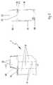
In Figur 1 ist das Funktionsprinzip schematisch dargestellt. Es zeigt einen Druckkopf 1 mit einem Gehäuse 10, in welchem ein Tintenvorratsraum 12 gebildet ist. Der Tintenvorratsraum 12 ist praktisch vollständig mit einem Schwamm 18 ausgefüllt, der dazu bestimmt ist, den eingebrachten bzw. einzubringenden Tintenvorrat aufzunehmen. Der Tintenvorratsraum 12 ist nach oben hin mit einer Zwischenplatte 20 verschlossen, die umlaufend auf einem Gehäuserand 14 abgedichtet aufliegt.The principle of operation is shown schematically in FIG. It shows a
Die Zwischenplatte 20 weist zwei Öffnungen auf, nämlich eine Befüllbohrung 22 sowie eine Belüftungsbohrung 24.The
Auf die Zwischenplatte 20 bzw. auf das Gehäuse 10 ist ein Deckel 50 aufgesetzt, wobei (hier nicht näher dargestellt) zwischen dem Deckel 50 und der Zwischenplatte 20 keine besondere Abdichtung vorgesehen ist bzw. bewußt ein Umfangsabschnitt vorhanden ist, durch den Luft aus- bzw. eintreten kann. Oberhalb der Befüllbohrung 22 und dieser exakt zugeordnet ist am Deckel 50 eine Durchtrittsöffnung 52 angebracht.On the
Insoweit entspricht der Druckkopf 1 grundsätzlich hinsichtlich seines Aufbaus den bisher bekannten Druckköpfen, wobei in der gewählten Art der Darstellung lediglich eine von mehreren Tintenvorratsräumen 12 sichtbar ist. Bei den hier besonders interessierenden Anwendungsfällen der Mehrfarben-Druckköpfe sind drei oder vier derartiger Tintenvorratsräume 12 vorgesehen, die durch Trennwände 16 (vgl. Figur 2) voneinander getrennt sind und unterschiedlichen Farbkomponenten aufnehmen.In this respect, the
Der Druckkopf 1 ist in eine (hier nur angedeutete) Befüllstation 100 eingesetzt, von der lediglich ein Kanülenträger 110 teilweise dargestellt ist. Der Kanülenträger 110 besitzt eine Kanüle 112, die den Deckel 50 an der Durchtrittsöffnung 52 mit etwas radialem Spiel durchsetzt und in den Tintenvorratsraum 12 bzw. des Schwamms 18 eingedrungen ist. Die Kanüle 112 ist somit durch die Zwischenplatte 20 hindurchgeführt, wobei ein Dichtungsorgan 114 den radialen Zwischenraum zwischen der Kanüle 112 und der Befüllbohrung 22 abdichtet.The
Nach oben hin endet die Kanüle 112 innerhalb einer im Kanülenträger 110 vorgesehenen Vertiefung 118, in welche eine Nachfüllpatrone 200 mit ihrem unteren Axialabschnitt 208 eingesetzt ist. Im Bereich der eingedrungenen Kanüle 112 ist an der Nachfüllpatrone 200 ein Stopfen 205 vorhanden, der von der Kanüle 112 durchstochen ist, so daß die Kanüle 112 abgedichtet in das Innere der Nachfüllpatrone 200 hineingeführt ist. Somit ist eine durchgehende, gegenüber der Umgebung abgedichtete Fließverbindung zwischen dem Tintenvorrat in der Nachfüllpatrone 200 und dem Tintenvorratsraum 12 des Druckkopfs 1 hergestellt.The
Zur Initiierung des Befüllvorgangs wird eine die Nachfüllpatrone 200 verschließende Kappe 210 (vgl. Figur 5) entfernt, so daß die Nachfüllpatrone 200 belüftet wird und Tinte über die Kanüle 112 in den Tintenvorratsraum 12 hineinfließen kann. Hierdurch wird im Tintenvorratsraum 12 Luft verdrängt, die entweichen muß, damit nicht infolge eines Druckaufbaus der Nachfüllvorgang vorzeitig zum Erliegen kommt. Hierzu ist in der Zwischenplatte 20 die Belüftungsbohrung 24 vorgesehen, durch die die Luft hindurchströmen muß, weil die Tintenvorratskammer 12 im übrigen dicht abgeschlossen ist. Während des Befüllvorgangs fließt permanent Tinte in den Tintenvorratsraum 12, so daß dieser zusehens mit Tinte gefüllt wird. Sobald das Aufnahmevermögen des Schwamms 18 erschöpft ist, kann darüber hinaus weiter Tinte zufließen, bis der Flüssigkeitsspiegel die Zwischenplatte 20 von unten erreicht. Dies ist immer dann der Fall, wenn der Tintenvorrat in der Nachfüllpatrone 200 größer ist als das Aufnahmevermögen der Tintenvorratskammer 12.To initiate the filling process, a
Um ein weiteres Zufließen von Tinte und damit ein Überfüllen des Tintenvorratsraums 12 zu verhindern, ist erfindungsgemäß in die Belüftungsbohrung 24 eine Membran 26 in Form eines Stopfens bzw. zylindrischen Körpers dicht eingesetzt. Die Membran ist so beschaffen, daß sie Luft hindurchläßt, andererseits jedoch den Durchtritt von Tinte verhindert. Aufgrund dieser Funktion kann während des Befüllvorgangs Luft verdrängt werden, so daß insoweit Tinte weitgehend ungehindert zufließen kann. Ein Überfüllen, d.h. ein Austreten von Tinte durch die Belüftungsbohrung 24 hindurch ist jedoch ausgeschlossen und der Befüllvorgang stoppt selbsttätig, sobald der Tintenvorratsraum 12 vollständig mit Tinte gefüllt ist. Die Membran ist so ausgelegt, daß sie unter den auftretenden Druckverhältnissen den Durchtritt von Tinte sicher verhindert.In order to prevent a further inflow of ink and thus an overfilling of the
Sobald der Befüllvorgang abgeschlossen ist, beispielsweise sobald das Einfließen von Tinte in den Tintenvorratsraum zum Erliegen gekommen ist, weil das Aufnahmevermögen der Tintenvorratskammer 12 erschöpft ist, wird die Nachfüllpatrone 200 von der Kanüle 112 abgezogen, wobei der Stopfen 205 infolge seiner selbstverschließenden Eigenschaft ein Ausfließen von Tinte verhindert, selbst für den Fall, daß noch größere Mengen an Tinte im Inneren verblieben sind. Anschließend der Kanülenträger 110 abgehoben und der Druckkopf 1 ist erneut einsatzbereit.As soon as the filling process has been completed, for example as soon as the ink flows into the ink supply space Has come to a standstill because the capacity of the
Im dargestellten Ausführungsbeispiel besteht noch die Gefahr, daß sich zwischen dem Schwamm 18 und der Zwischenplatte 20 überstehende Tinte befindet, die durch die Befüllöffnung 22 austreten kann. Diese Gefahr besteht nicht, wenn das Dichtungsorgan 114 nicht an der Kanüle 112, sondern an der Zwischenplatte 20 befestigt ist und darüber hinaus aus einem selbstverschließenden Material, ähnlich demjenigen des Stopfens 205, besteht, so daß beim Herausziehen der Kanüle 112 das Dichtorgan 114 die Eindringstelle dicht verschließt. Alternativ kann auch der Tintenvorratsraum 12 vollständig mit Schwammaterial ausgefüllt sein, so daß kein vorstehend beschriebener Zwischenraum entsteht.In the illustrated embodiment, there is still the risk that there is protruding ink between the
Weitere Alternativen bestehen darin, im Inneren des Gehäuses 10 hier nicht dargestellte Beutel oder dergleichen vorzusehen, die insoweit in sich abgeschlossen sind.Further alternatives consist in providing bags or the like, not shown here, in the interior of the
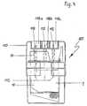
In Figur 2 ist ein Druckkopf 1 in Form eines Mehrfarben-Druckkopfs dargestellt. Im Inneren des Gehäuses 10 sind drei Tintenvorratsräume 12 gebildet, die die Farbkomponenten Magenta, Cyan und Gelb enthalten. Zu diesem Zweck sind im Gehäuse 10 zwei durchgehende Trennwände 16 angebracht, die in der vorstehend beschriebenen Art und Weise gestaltet sind. Unten ist im Gehäuse 10 ein Tintenkanal 28 angeordnet, der die Verbindung zwischen den Tintenräumen 12 und der (nicht dargestellten) Düsenplatte herstellt.FIG. 2 shows a
Wiederum ist der Deckel 50 mit Durchtrittsöffnungen 52 versehen, die die Zugänglichkeit zu den Tintenvorratsräumen 12 zum Zwecke der Tintenzufuhr ermöglichen und exakt oberhalb der jeweiligen Befüllbohrungen 22 positioniert sind. Der Deckel 50 ist teilweise erhaben ausgeführt, wobei die Durchtrittsöffnungen 52 in unterschiedlichen Abschnitten liegen. Hinsichtlich seiner äußeren Kontur entspricht der Deckel 50 praktisch demjenigen des bisherigen Einweg-Druckkopfs bzw. dem eingangs beschriebenen Deckel zum Umrüsten eines Einweg-Druckkopfs in einen Mehrweg-Druckkopf. Er gewährleistet damit die volle Kompatibilität zu den bisherigen Druckköpfen, wie sie werkseitig von den Herstellern von Tintenstrahldruckern eingebaut werden.Again, the
In der in Figur 3 dargestellten Ausführungsvariante ist die stopfenförmige Membran 26 durch eine flächige Membran 36 ersetzt, die vollständig umlaufend am Gehäuserand 14 und vollständig durchgehend stirnseitig an den Kammerwänden 16 verschweißt ist. Dies ist in der rechten Teilabbildung in Form der gestrichelten Schweißnaht 38 angedeutet.In the embodiment variant shown in FIG. 3, the stopper-shaped
Der Vorteil dieser Ausführungsvariante liegt in der besonders einfachen und kostengünstigen Art der Herstellung. So ist es nicht mehr erforderlich, für jeden der drei Tintenvorratsräume 12 einzelne Belüftungsventile vorzusehen, vielmehr genügt eine einzige, durchgehende Folie.The advantage of this embodiment variant lies in the particularly simple and inexpensive type of manufacture. It is no longer necessary to provide 12 individual ventilation valves for each of the three ink supply spaces, rather a single, continuous film is sufficient.
Weiterhin entfällt die Zwischenplatte 20 vollständig, da die Membran 36 nunmehr die Tintenvorratsräume 12 nach oben hin verschließt. Voraussetzung hierfür ist allerdings, daß die Membran 36 aus einem selbstverschließenden Material besteht, so daß Einstichstellen 40 während des Befüllvorgangs die hindurchgeführten Kanülen 112 dicht umfassen.Furthermore, the
Auch können Folien als kostengünstige Alternative zu den vorstehend beschriebenen stopfenförmigen Membranen verwendet werden, auch wenn sie eine selbstverschließende Eigenschaft nicht besitzen. Voraussetzung hierfür ist, daß weiterhin Zwischenplatten oder dergleichen mit abdichtbaren oder abgedichteten Befüllöffnungen verwendet werden.Films can also be used as an inexpensive alternative to the stopper-shaped membranes described above, even if they do not have a self-sealing property. The prerequisite for this is that intermediate plates or the like with sealable or sealed filling openings continue to be used.
Bei ausreichender Eigenstabilität, d.h. bei plattenförmigen Membranen (beispielsweise aus keramischen Werkstoffen), kann ebenfalls auf eine Zwischenplatte verzichtet werden, wobei es dann erforderlich ist, die Befüllöffnungen direkt in der Membran anzubringen.With sufficient inherent stability, i.e. in the case of plate-shaped membranes (for example made of ceramic materials), an intermediate plate can also be dispensed with, in which case it is then necessary to make the filling openings directly in the membrane.
Figur 4 zeigt den in Figur 2 dargestellten Druckkopf 1, der in eine als Befüllstation ausgebildete Vorrichtung 100 eingesetzt ist. Insbesondere ist der Kanülenträger 110 zu erkennen, der drei Kanülen 112 trägt, welche (gleichzeitig) in das Innere des Druckkopfs 1 hineingeführt sind. Weiterhin sind drei Vertiefungen 118a, 118b, 118c vorhanden, die zur Aufnahme der Nachfüllpatronen 200 dienen. Die Vertiefungen 118a, 118b, 118c besitzen drei verschiedene Grundrisse, auf die exakt abgestimmt die unteren axialen Abschnitte 208 der Nachfüllpatrone 200 gestaltet sind. Die Grundrißformen sind so gewählt, daß nur bei farbkorrekter Zuordnung ein Aufstekken der jeweiligen Nachfüllpatrone 200 gewährleistet ist. Im vorliegenden Fall sind als Grundrißform ein Kreis (Vertiefung 118a), ein Rechteck (Vertiefung 118b) sowie ein Sechseck (Vertiefung 118c) vorgesehen.FIG. 4 shows the
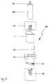
In Figur 5 sind die Hauptbestandteile der Vorrichtung 100 in Explosionsdarstellung wiedergegeben. Diese bestehen im wesentlichen aus einer Halterung, die durch ein Halterungsgehäuse 102 mit eingesetztem Halterungseinsatz 104 und dem Kanülenträger 110 bestehen. Der Halterungseinsatz 104 trägt ein Dichtungsorgan 107, das auf die Düsenplatte des Druckkopfs 1 ausgerichtet ist. Die Dichtwirkung wird nach dem Einsetzen des Druckkopfs 1 dadurch erzielt, daß ein Arretierorgan 105 diesen unter Vorspannung gegen das Dichtungsorgan 107 gedrückt hält. Insoweit entspricht die Vorrichtung 100 dem Grunde nach der eingangs beschriebenen Vorrichtung aus dem Stand der Technik. Die erfindungsgemäße Weiterbildung besteht im wesentlichen in der Gestaltung des Kanülenträgers 110, wie in er in zwei Ausführungsvarianten in den Figuren 6 und 7 dargestellt ist.5 shows the main components of the
In Figur 6 ist eine Ausführungsvariante dargestellt, die bei solchen Druckköpfen Anwendung findet, die mit einem Belüftungsventil versehen sind und somit im wesentlichen den vorstehend beschriebenen Druckköpfen entsprechen. In diesem Fall ist es wesentlich, daß der Kanülenträger 110 so gestaltet ist, daß die Kanüle 112 abgedichtet in das Innere des Tintenvorratsraums 12 eingesetzt werden kann. Dies wird dadurch erreicht, daß die Kanüle 112 mit einem Kanülenrohr 116 umgeben ist, das stirnseitig konisch ausläuft und somit als Dichtungskonus 114 gestaltet ist. Der Dichtungskonus 114 wird zur Anlage an den Rand der Befüllöffnung 22 des Druckkopfs 1 gedrückt und dichtet auf diese Weise den Übergang zum Tintenvorratsraum ab.FIG. 6 shows an embodiment variant which is used in print heads which are provided with a ventilation valve and thus essentially correspond to the print heads described above. In this case, it is essential that the
Alternativ hierzu kann auch eine Variante verwendet werden, wie sie im Zusammenhang mit der Ausführung gemäß Figur 1 beschrieben ist.As an alternative to this, a variant can also be used, as described in connection with the embodiment according to FIG. 1.
Die in Figur 7 dargestellte Variante besitzt ein Entlüftungsrohr 124, welches eine Membran 126 aufnimmt. Weiterhin ist ein als Dichtungsorgan wirkender konischer Axialabschnitt 125 endseitig vorhanden, so daß eine dichte Verbindung zwischen dem Tintenvorratsraum und der Umgebung über eine ohnehin im Druckkopf 1 vorhandene Belüftungsbohrung 26 herstellt. Die Membranfunktion ist damit nicht im Druckkopf 1 selbst, sondern am Kanülenträger 110 realisiert, so daß sich diese Variante speziell als Nachrüstvariante für bereits vorhandene Befüllstationen eignet. Insbesondere entfällt die Notwendigkeit, die Druckkköpfe selbst umzurüsten, so daß insoweit eine Vielzahl im Umlauf befindlicher Druckköpfe herkömmlicher Bauart mit Belüftungsöffnungen ohne Funktionseinbuße wiederbefüllt werden können. So ist es in aller Regel ausreichend, die beschriebene Membranfunktion als Überlaufschutz lediglich temporär, nämlich während des Befüllvorgangs selbst, zur Verfügung zu haben, wobei diese Funktion nach Abschluß des Befüllvorgangs in vielen Fällen entbehrlich ist.The variant shown in FIG. 7 has a vent pipe 124 which receives a
Als Material für die Membran eignen sich prinzipiell sämtliche gängigen Materialien, sofern sie die angesprochene Eigenschaft besitzen. Es sind dies einerseits Polymere, wie beispielsweise Polyamid oder Polyäthylen, aus denen sich auch Folien herstellen lassen. Andererseits bieten sich auch keramische Werkstoffe an, die insbesondere chemisch beständig sind.In principle, all common materials are suitable as material for the membrane, provided that they have the property mentioned. On the one hand, these are polymers, such as polyamide or polyethylene, from which films can also be produced. On the other hand, there are also ceramic materials that are particularly chemically resistant.
- 11
- - Druckkopf- printhead
- 1010th
- - Gehäuse- Casing
- 1212th
- - Tintenvorratsraum- Ink supply room
- 1414
- - Gehäuserand- Housing edge
- 1616
- - Trennwand- Partition wall
- 1818th
- - Schwamm- Sponge
- 2020th
- - Zwischenplatte- intermediate plate
- 2222
- - Befüllbohrung- filling hole
- 2424th
- - Belüftungsbohrung- ventilation hole
- 2626
- - Membran- membrane
- 2828
- - Tintenkanal- ink channel
- 3636
- - Membranfolie- membrane film
- 3838
- - Schweißnaht- Weld
- 4040
- - Einstichstelle- puncture site
- 5050
- - Deckel- lid
- 5252
- - Durchtrittsöffnung- passage opening
- 100100
- - Befüllstation- filling station
- 102102
- - Halterungsgehäuse- bracket housing
- 104104
- - Halterungseinsatz- Bracket insert
- 105105
- - Arretierorgan- locking device
- 107107
- - Dichtungsorgan- sealing member
- 110110
- - Kanülenträger- cannula holder
- 112112
- - Kanüle- cannula
- 114114
- - Dichtungsorgan- sealing member
- 116116
- - Kanülenrohr- cannula tube
- 118118
- - Vertiefung- Deepening
- 124124
- - Entlüftungsrohr- vent pipe
- 125125
- - Dichtungsorgan- sealing member
- 126126
- - Membran- membrane
- 200200
- - Nachfüllpatrone- Refill cartridge
- 205205
- - Stopfen- Plug
- 208208
- - Axialabschnitt- axial section
- 210210
- - Kappe- cap
Claims (26)
Translated fromGermanPriority Applications (1)
| Application Number | Priority Date | Filing Date | Title |
|---|---|---|---|
| DE29521667UDE29521667U1 (en) | 1994-09-24 | 1995-08-29 | Printhead for an inkjet printer and device for refilling such a printhead |
Applications Claiming Priority (2)
| Application Number | Priority Date | Filing Date | Title |
|---|---|---|---|
| DE4434186 | 1994-09-24 | ||
| DE19944434186DE4434186A1 (en) | 1994-09-24 | 1994-09-24 | Printhead for an inkjet printer and device for refilling such a printhead |
Publications (1)
| Publication Number | Publication Date |
|---|---|
| EP0704308A1true EP0704308A1 (en) | 1996-04-03 |
Family
ID=6529118
Family Applications (1)
| Application Number | Title | Priority Date | Filing Date |
|---|---|---|---|
| EP95113526AWithdrawnEP0704308A1 (en) | 1994-09-24 | 1995-08-29 | Printhead for an ink jet printer and device for refilling such a printhead |
Country Status (2)
| Country | Link |
|---|---|
| EP (1) | EP0704308A1 (en) |
| DE (1) | DE4434186A1 (en) |
Cited By (5)
| Publication number | Priority date | Publication date | Assignee | Title |
|---|---|---|---|---|
| EP0816100A3 (en)* | 1996-06-28 | 1998-06-10 | Mitsubishi Pencil Corporation of America | Method and apparatus for refilling a print cartridge |
| EP0921005A3 (en)* | 1997-12-03 | 1999-12-08 | Hewlett-Packard Company | Method and apparatus for venting an ink container |
| KR100332609B1 (en)* | 1998-05-11 | 2002-06-20 | 정광춘 | Method and kit for replugging a ink of ink cartridge |
| EP2251202A1 (en)* | 2009-05-14 | 2010-11-17 | Pelikan Hardcopy Production AG | Ink cartridge and accompanying ink jet printer |
| FR2969958A1 (en)* | 2011-01-04 | 2012-07-06 | Bihan Thierry Le | PRINTER CARTRIDGE INK FILLING DEVICE |
Families Citing this family (3)
| Publication number | Priority date | Publication date | Assignee | Title |
|---|---|---|---|---|
| US5877795A (en)* | 1996-05-24 | 1999-03-02 | Hewlett-Packard Co. | Methods and designs to purge air from ink tubes during initial startup |
| DE10116429B4 (en) | 2001-04-02 | 2005-03-24 | J. S. Staedtler Gmbh & Co. Kg | Device for filling an ink tank |
| US7473302B2 (en)* | 2004-12-28 | 2009-01-06 | Canon Kabushiki Kaisha | Liquid housing container and liquid supply apparatus |
Citations (8)
| Publication number | Priority date | Publication date | Assignee | Title |
|---|---|---|---|---|
| US4571599A (en)* | 1984-12-03 | 1986-02-18 | Xerox Corporation | Ink cartridge for an ink jet printer |
| US4771295A (en)* | 1986-07-01 | 1988-09-13 | Hewlett-Packard Company | Thermal ink jet pen body construction having improved ink storage and feed capability |
| EP0381363A2 (en) | 1989-01-31 | 1990-08-08 | Hewlett-Packard Company | Ink supply for a thermal ink jet pen |
| US4967207A (en)* | 1989-07-26 | 1990-10-30 | Hewlett-Packard Company | Ink jet printer with self-regulating refilling system |
| US4968998A (en)* | 1989-07-26 | 1990-11-06 | Hewlett-Packard Company | Refillable ink jet print system |
| WO1992020577A1 (en)* | 1991-05-17 | 1992-11-26 | Graphic Utilities, Inc. | Method and apparatus for refilling ink cartridges |
| DE4235029C2 (en) | 1992-10-19 | 1994-07-14 | Pms Gmbh Prod & Recycling | Cover for a printhead of an inkjet printer |
| EP0638427A2 (en)* | 1993-08-13 | 1995-02-15 | PMS GmbH, Produktion + Recycling von Büromaschinenzubehör | Apparatus, kit and method for filling a printhead of an ink jet printer |
Family Cites Families (4)
| Publication number | Priority date | Publication date | Assignee | Title |
|---|---|---|---|---|
| DE3401071A1 (en)* | 1984-01-13 | 1985-07-25 | Siemens AG, 1000 Berlin und 8000 München | Device for refilling ink containers in inking apparatuses |
| US5510820A (en)* | 1992-04-22 | 1996-04-23 | Lexmark International, Inc. | Device for ink refill of a reservoir in a print cartridge |
| NL9200767A (en)* | 1992-04-28 | 1993-11-16 | Hubertus Antonius Johannes Sme | METHOD AND HOLDER FOR REFILLING INK-PRINTING DEVICES AND SIMILAR INK CARTRIDGES. |
| DE9417235U1 (en)* | 1994-08-06 | 1995-01-12 | PMS GmbH Produktion + Recycling von Büromaschinenzubehör, 78664 Eschbronn | Device and kit for filling a printhead of an inkjet printer |
- 1994
- 1994-09-24DEDE19944434186patent/DE4434186A1/ennot_activeWithdrawn
- 1995
- 1995-08-29EPEP95113526Apatent/EP0704308A1/ennot_activeWithdrawn
Patent Citations (10)
| Publication number | Priority date | Publication date | Assignee | Title |
|---|---|---|---|---|
| US4571599A (en)* | 1984-12-03 | 1986-02-18 | Xerox Corporation | Ink cartridge for an ink jet printer |
| US4771295A (en)* | 1986-07-01 | 1988-09-13 | Hewlett-Packard Company | Thermal ink jet pen body construction having improved ink storage and feed capability |
| US4771295B1 (en)* | 1986-07-01 | 1995-08-01 | Hewlett Packard Co | Thermal ink jet pen body construction having improved ink storage and feed capability |
| EP0381363A2 (en) | 1989-01-31 | 1990-08-08 | Hewlett-Packard Company | Ink supply for a thermal ink jet pen |
| US4967207A (en)* | 1989-07-26 | 1990-10-30 | Hewlett-Packard Company | Ink jet printer with self-regulating refilling system |
| US4968998A (en)* | 1989-07-26 | 1990-11-06 | Hewlett-Packard Company | Refillable ink jet print system |
| WO1992020577A1 (en)* | 1991-05-17 | 1992-11-26 | Graphic Utilities, Inc. | Method and apparatus for refilling ink cartridges |
| DE4235029C2 (en) | 1992-10-19 | 1994-07-14 | Pms Gmbh Prod & Recycling | Cover for a printhead of an inkjet printer |
| EP0638427A2 (en)* | 1993-08-13 | 1995-02-15 | PMS GmbH, Produktion + Recycling von Büromaschinenzubehör | Apparatus, kit and method for filling a printhead of an ink jet printer |
| DE4327178C1 (en) | 1993-08-13 | 1995-03-09 | Pms Gmbh Prod & Recycling | Device for refilling a printhead of an inkjet printer |
Cited By (9)
| Publication number | Priority date | Publication date | Assignee | Title |
|---|---|---|---|---|
| EP0816100A3 (en)* | 1996-06-28 | 1998-06-10 | Mitsubishi Pencil Corporation of America | Method and apparatus for refilling a print cartridge |
| US5845682A (en)* | 1996-06-28 | 1998-12-08 | Mitsubishi Pencil Corporation Of America | Apparatus for refilling an ink cartridge |
| EP0921005A3 (en)* | 1997-12-03 | 1999-12-08 | Hewlett-Packard Company | Method and apparatus for venting an ink container |
| US6074050A (en)* | 1997-12-03 | 2000-06-13 | Hewlett-Packard Company | Method and apparatus for venting an ink container |
| KR100604493B1 (en)* | 1997-12-03 | 2006-09-22 | 휴렛-팩커드 컴퍼니(델라웨어주법인) | Method and apparatus for venting an ink container |
| KR100332609B1 (en)* | 1998-05-11 | 2002-06-20 | 정광춘 | Method and kit for replugging a ink of ink cartridge |
| EP2251202A1 (en)* | 2009-05-14 | 2010-11-17 | Pelikan Hardcopy Production AG | Ink cartridge and accompanying ink jet printer |
| FR2969958A1 (en)* | 2011-01-04 | 2012-07-06 | Bihan Thierry Le | PRINTER CARTRIDGE INK FILLING DEVICE |
| WO2012093230A1 (en)* | 2011-01-04 | 2012-07-12 | Thierry Le Bihan | Device for filling a printer cartridge with ink |
Also Published As
| Publication number | Publication date |
|---|---|
| DE4434186A1 (en) | 1996-03-28 |
Similar Documents
| Publication | Publication Date | Title |
|---|---|---|
| EP0638427B1 (en) | Apparatus, kit and method for filling a printhead of an ink jet printer | |
| DE2833660C2 (en) | Exchangeable supply cartridge | |
| DE69832201T2 (en) | Cartridge for inkjet printers | |
| DE10116429B4 (en) | Device for filling an ink tank | |
| DE60311837T2 (en) | LIQUID DISPENSER WITH DISPOSABLE MIXING CHAMBER | |
| DE69514060T2 (en) | Ink cartridge for inkjet printers | |
| DE3203795A1 (en) | "INK RADIATOR PRODUCTION DEVICE" | |
| DE10341787B4 (en) | ink cartridge | |
| DE19512812C2 (en) | Refill unit for insertion into an empty ink cartridge unit | |
| DE19615925A1 (en) | Inked printer and ink supply tank | |
| DE102007040108A1 (en) | Apparatus for refilling an ink cartridge for an inkjet printer | |
| EP0704308A1 (en) | Printhead for an ink jet printer and device for refilling such a printhead | |
| EP4089161A1 (en) | Substrate for testing samples and system comprising the substrate | |
| DE29507743U1 (en) | Printhead for an ink jet printer | |
| EP0085957A2 (en) | Appliance for drawing fluids from enclosed sterile containers | |
| DE4121962A1 (en) | Ink jet reservoir for bubble jet printer - has plastic enclosure filled with ink absorbent foam with ventilation chamber to provide connection to atmosphere | |
| EP2212117B1 (en) | Ink cartridge, especially for an ink jet printer | |
| DE29521667U1 (en) | Printhead for an inkjet printer and device for refilling such a printhead | |
| DE4235029C2 (en) | Cover for a printhead of an inkjet printer | |
| DE3910787C1 (en) | ||
| EP1556224B1 (en) | Ink cartridge to be mounted on a recording head | |
| WO2009103421A2 (en) | Method and device for refilling an ink cartridge for an ink-jet printer | |
| DE19962662B4 (en) | Ink cartridge and method of making an ink cartridge | |
| DE3238063A1 (en) | Interchangeable container with an ink reservoir chamber for an ink printing unit | |
| DE9417235U1 (en) | Device and kit for filling a printhead of an inkjet printer |
Legal Events
| Date | Code | Title | Description |
|---|---|---|---|
| PUAI | Public reference made under article 153(3) epc to a published international application that has entered the european phase | Free format text:ORIGINAL CODE: 0009012 | |
| AK | Designated contracting states | Kind code of ref document:A1 Designated state(s):AT CH DE GB LI | |
| 17P | Request for examination filed | Effective date:19960710 | |
| 17Q | First examination report despatched | Effective date:19970606 | |
| GRAG | Despatch of communication of intention to grant | Free format text:ORIGINAL CODE: EPIDOS AGRA | |
| GRAG | Despatch of communication of intention to grant | Free format text:ORIGINAL CODE: EPIDOS AGRA | |
| GRAH | Despatch of communication of intention to grant a patent | Free format text:ORIGINAL CODE: EPIDOS IGRA | |
| STAA | Information on the status of an ep patent application or granted ep patent | Free format text:STATUS: THE APPLICATION IS DEEMED TO BE WITHDRAWN | |
| 18D | Application deemed to be withdrawn | Effective date:19981125 |