EP0703364A1 - Method and device for driving a micropump - Google Patents
Method and device for driving a micropumpDownload PDFInfo
- Publication number
- EP0703364A1 EP0703364A1EP95112161AEP95112161AEP0703364A1EP 0703364 A1EP0703364 A1EP 0703364A1EP 95112161 AEP95112161 AEP 95112161AEP 95112161 AEP95112161 AEP 95112161AEP 0703364 A1EP0703364 A1EP 0703364A1
- Authority
- EP
- European Patent Office
- Prior art keywords
- driver signal
- valve structure
- micropump
- pump
- resonance
- Prior art date
- Legal status (The legal status is an assumption and is not a legal conclusion. Google has not performed a legal analysis and makes no representation as to the accuracy of the status listed.)
- Granted
Links
Images


Classifications
- F—MECHANICAL ENGINEERING; LIGHTING; HEATING; WEAPONS; BLASTING
- F04—POSITIVE - DISPLACEMENT MACHINES FOR LIQUIDS; PUMPS FOR LIQUIDS OR ELASTIC FLUIDS
- F04B—POSITIVE-DISPLACEMENT MACHINES FOR LIQUIDS; PUMPS
- F04B43/00—Machines, pumps, or pumping installations having flexible working members
- F04B43/02—Machines, pumps, or pumping installations having flexible working members having plate-like flexible members, e.g. diaphragms
- F04B43/04—Pumps having electric drive
- F04B43/043—Micropumps
- F—MECHANICAL ENGINEERING; LIGHTING; HEATING; WEAPONS; BLASTING
- F04—POSITIVE - DISPLACEMENT MACHINES FOR LIQUIDS; PUMPS FOR LIQUIDS OR ELASTIC FLUIDS
- F04B—POSITIVE-DISPLACEMENT MACHINES FOR LIQUIDS; PUMPS
- F04B19/00—Machines or pumps having pertinent characteristics not provided for in, or of interest apart from, groups F04B1/00 - F04B17/00
- F04B19/006—Micropumps
- F—MECHANICAL ENGINEERING; LIGHTING; HEATING; WEAPONS; BLASTING
- F04—POSITIVE - DISPLACEMENT MACHINES FOR LIQUIDS; PUMPS FOR LIQUIDS OR ELASTIC FLUIDS
- F04B—POSITIVE-DISPLACEMENT MACHINES FOR LIQUIDS; PUMPS
- F04B2203/00—Motor parameters
- F04B2203/04—Motor parameters of linear electric motors
- F04B2203/0404—Frequency of the electric current
Definitions
- the present inventionrelates to a method and a device for controlling a micropump by means of a driver signal such that a conveying direction defined by a valve structure is reversed.
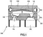
- Micro diaphragm pumpsare known for example from WO-93/05295. One of the pumps described there is shown in Fig. 1.
- This micro-diaphragm pump 100comprises a two-part displacement unit 102 and also a two-part valve unit 104.
- the two parts of the displacement unit 102comprise a flexible pump diaphragm 106 and a rigid counter electrode 108.
- a so-called drive chamber 110is formed between the pump diaphragm 106 and a counter chamber 108.
- the pump membrane 106is attracted by the counter electrode 108.
- the volume of the pump chamber 112increases and a fluid to be pumped is sucked in via an inlet.
- the pump membrane 106relaxes in its output region and displaces the fluid to be pumped into the outlet 116.
- Two passive check valves 118, 120which define a preferred direction for the fluid flow, result in a directional pumping action when the displacement unit 102 is periodically activated from inlet 114 to outlet 116 of the pump.
- the behavior of the valves 118, 120is quasi static, ie the position of the movable valve part results at all times from the hydrostatic pressure difference applied across the valve.
- Known methods for controlling such a micro diaphragm pumpenable a fluid to be pumped in the preferred direction defined by the valves 118, 120.
- micromembrane pumpIn technical applications of the micromembrane pump, the situation often arises in which fluids, for example, both have to be transported to a sensor element and have to be removed again. This occurs, for example, in chemical analysis, in which liquids both have to be transported to a sensor element and have to be removed again. So far, a micro-diaphragm pump has to be used both for the forward transport and for the removal, these micro-diaphragm pumps being arranged in opposite directions. The need for the two micro diaphragm pumps increases the complexity of such analytical systems and their manufacturing costs and makes it difficult to fill them with a fluid when operating these systems.
- the present inventionis based on the object of creating a method and a device for controlling a micropump which make it possible to reverse the conveying direction defined by a valve structure.
- the present inventionprovides a method for controlling a micro-diaphragm pump by means of a driver signal, the micro-diaphragm pump having a delivery direction defined by a valve structure, with the method step of applying the driver signal to the excitation frequency Micro diaphragm pump, the excitation frequency being in the range above a resonance of a system formed from the moving parts of the micro diaphragm pump and the fluid to be pumped, as a result of which the delivery direction defined by a valve structure is reversed.
- the present inventionprovides a device for controlling a micro-diaphragm pump by means of a driver signal, the micro-diaphragm pump having a delivery direction defined by a valve structure, with a device for generating the driver signal with an excitation frequency which is in the range above a resonance of one of the movable ones Parts of the micro-diaphragm pump and the system to be pumped fluid is located, whereby the delivery direction defined by a valve structure is reversed.
- An advantage of the present inventionis that for practical applications in which both a transport and a transport of fluids to an element is required, only a micro-diaphragm pump has to be used, whereby the required space is reduced.
- Another advantageis that the filling of such systems with a fluid is made easier.
- Yet another advantageis that the manufacturing cost of such systems can be significantly reduced.
- the method according to the invention and the device according to the inventionmake it possible to reverse the pumping direction in micro-diaphragm pumps (see FIG. 1) with so-called passive check valves 118, 120.
- the displacement unit 102is acted upon by a driver signal which has an operating frequency in the region of a resonance, which is essentially defined by the movable valve parts, which lies above this resonance.
- this resonanceis a resonance of a system which is formed from the moving parts of the micro diaphragm pump (106, 118, 120) and from the fluid to be pumped.
- This behaviorcorresponds to that of an oscillatory, mechanical system, which is stimulated to a forced oscillation by an external force.
- the amplitude of the vibrationhas the known resonance behavior.
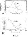
- the curves 200 and 202 shown in FIG. 2represent the course of the deflection and the phase shift with different damping or quality factors.
- the course of the curve 200is assigned a quality factor of 3 and the course of the curve 202 is assigned a quality factor of 1 .
- the deflection and phase shift of a movable valve part shown in FIG. 2applies to a resonance of this part of 3000 Hz.
- the curves in the first lineindicate the so-called exciting pressure
- the signal curves in the middle lineindicate the opening state of the movable valve
- the signal curves in the lower rowshow the time-dependent flow
- the respective y-scales in any Unitsare shown.
- the second effectis that the valve can only be opened in the positive direction (see second line of Fig. 3), i.e. the valve is completely closed for half a period.
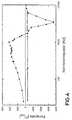
- the micro diaphragm pumpIn the frequency range from 1 Hz to 1 kHz, the micro diaphragm pump is in its so-called standard operating range, which is shown by arrow 400. In this standard operating range 400, the micro diaphragm pump has a positive pumping rate ( ⁇ > 0), which corresponds to a forward pumping effect.
- the micro diaphragm pumpIn the frequency range from 2 kHz to 6 kHz, which is represented by the arrow 410, the micro diaphragm pump has a negative pumping rate ( ⁇ ⁇ 0), which corresponds to a backward pumping effect.
- the resonance frequency of the movable valve parts used in a micro diaphragm pumpcan be varied by a suitable change in the shape of the valves used. This makes it possible to influence the frequency range 410 in which the negative pumping rate occurs.
- the frequency range 410 where a negative pumping rate occursis the frequency range where there is a phase difference of about 90 degrees to about 180 degrees between the drive signal and the deflection of the valves.
- the frequency range in which a positive pumping rate occursis that frequency range in which a phase difference of approximately 0 degrees to 90 degrees occurs between the driver signal and the deflection of the valve structure.
- FIG. 5shows a block diagram of the arrangement of a device for generating a driver signal and a micro diaphragm pump.
- the device according to the invention for controlling a micro-diaphragm pump 510 by means of a driver signalcomprises a device 500 for generating the driver signal with an excitation frequency which lies in the range above a resonance of the system formed from the moving parts of the micro-diaphragm pump 510 and the fluid to be pumped.
- the driver signalis over one or more Signal lines 520 applied to the micro diaphragm pump 510.
- the driver signal generating devicegenerates a second driver signal with a second excitation frequency, which is in a range in which a phase difference of approximately 0 degrees to 90 degrees occurs between the driver signal and the deflection of the valve structure, in order to fluid to be pumped into that defined by the valve structure Pump direction of pumping.
- the method according to the invention and the device according to the inventionare not limited to micro-diaphragm pumps that use check valves.
- the application of the invention to micro diaphragm pumps which use passive valves of a different designis readily possible.
- the application of the present inventionis not limited to a micro diaphragm pump that uses two valves.
- the use of micro diaphragm pumps that use one valve or more than two valvesis easily possible.
- piezoelectric and pneumatic or thermopneumatic drive mechanisms for the micro diaphragm pumpare also possible.
- a two-phase thermal driveis also contemplated, in which a liquid is heated in a drive chamber, whereby a vapor bubble is formed, through which a pump membrane is actuated by displacement.
- the thermal two-phase driveenables higher pressures to be generated than a purely thermopneumatic drive.
- a piston displacercan also be considered in addition to a membrane displacer.
Landscapes
- Engineering & Computer Science (AREA)
- Mechanical Engineering (AREA)
- General Engineering & Computer Science (AREA)
- Reciprocating Pumps (AREA)
Abstract
Description
Translated fromGermanDie vorliegende Erfindung bezieht sich auf ein Verfahren und eine Vorrichtung zur Ansteuerung einer Mikropumpe mittels eines Treibersignals, derart daß sich eine durch eine Ventilstruktur definierte Förderrichtung umkehrt.The present invention relates to a method and a device for controlling a micropump by means of a driver signal such that a conveying direction defined by a valve structure is reversed.
Mikro-Membranpumpen sind beispielsweise aus der WO-93/05295 bekannt. Eine der dort beschriebenen Pumpen ist in Fig. 1 dargestellt.Micro diaphragm pumps are known for example from WO-93/05295. One of the pumps described there is shown in Fig. 1.
Diese Mikro-Membranpumpe 100 umfaßt eine aus zwei Teilen bestehende Verdrängereinheit 102 und eine ebenfalls aus zwei Teilen bestehende Ventileinheit 104. Bei dieser Mikro-Membranpumpe umfassen die zwei Teile der Verdrängereinheit 102 eine flexible Pumpmembran 106 und eine starre Gegenelektrode 108. Zwischen der Pumpmembran 106 und der Gegenelektrode 108 ist eine sogenannte Antriebskammer 110 gebildet. Beim Anlegen einer Betriebsspannung wird die Pumpmembran 106 von der Gegenelektrode 108 angezogen. Das Volumen der Pumpkammer 112 vergrößert sich und ein zu pumpendes Fluid wird über einen Einlaß angesaugt. Beim Abschalten der Betriebsspannung relaxiert die Pumpmembran 106 in ihren Ausgangsbereich und verdrängt das zu pumpende Fluid in den Auslaß 116. Durch zwei passive Rückschlagventile 118, 120, die für die Fluidströmung eine Vorzugsrichtung definieren, ergibt sich bei einer periodischen Ansteuerung der Verdrängereinheit 102 eine gerichtete Pumpwirkung vom Einlaß 114 zum Auslaß 116 der Pumpe. Bei Betriebsfrequenzen, die weit unterhalb der Eigenfrequenz der beweglichen Ventilteile liegen, ist das Verhalten der Ventile 118, 120 quasi statisch, d.h. die Stellung des beweglichen Ventilteils ergibt sich zu jedem Zeitpunkt aus der über das Ventil anliegenden hydrostatischen Druckdifferenz.This
Bekannte Verfahren zur Ansteuerung einer solchen Mikro-Membranpumpe ermöglichen das Pumpen eines Fluids in die durch die Ventile 118, 120 definierte Vorzugsrichtung.Known methods for controlling such a micro diaphragm pump enable a fluid to be pumped in the preferred direction defined by the
Bei technischen Anwendungen der Mikromembranpumpe tritt oft die Situation ein, in der Fluide beispielsweise sowohl zu einem Sensorelement hintransportiert als auch wieder abtransportiert werden müssen. Dies tritt beispielsweise bei der chemischen Analytik auf, bei der Flüssigkeiten sowohl zu einem Sensorelement hintransportiert als auch wieder abtransportiert werden müssen. Sowohl für den Hintransport als auch für den Abtransport muß bislang jeweils eine Mikro-Membranpumpe eingesetzt werden, wobei diese Mikro-Membranpumpen entgegengesetzt angeordnet sind. Die Notwendigkeit der zwei Mikro-Membranpumpen erhöht die Komplexität solcher analytischer Systeme und deren Herstellungskosten und erschwert beim Betrieb dieser Systeme deren Befüllung mit einem Fluid erheblich.In technical applications of the micromembrane pump, the situation often arises in which fluids, for example, both have to be transported to a sensor element and have to be removed again. This occurs, for example, in chemical analysis, in which liquids both have to be transported to a sensor element and have to be removed again. So far, a micro-diaphragm pump has to be used both for the forward transport and for the removal, these micro-diaphragm pumps being arranged in opposite directions. The need for the two micro diaphragm pumps increases the complexity of such analytical systems and their manufacturing costs and makes it difficult to fill them with a fluid when operating these systems.
Ausgehend von diesem Stand der Technik liegt der vorliegenden Erfindung die Aufgabe zugrunde, ein Verfahren und eine Vorrichtung zur Ansteuerung einer Mikropumpe zu schaffen, die eine Umkehr der durch eine Ventilstruktur definierten Förderrichtung ermöglichen.Proceeding from this prior art, the present invention is based on the object of creating a method and a device for controlling a micropump which make it possible to reverse the conveying direction defined by a valve structure.
Diese Aufgabe wird durch ein Verfahren und eine Vorrichtung zur Ansteuerung einer Mikropumpe nach Anspruch 1 und nach Anspruch 6 gelöst.This object is achieved by a method and a device for controlling a micropump according to claim 1 and according to claim 6.
Die vorliegende Erfindung schafft ein Verfahren zur Ansteuerung einer Mikro-Membranpumpe mittels eines Treibersignals, wobei die Mikro-Membranpumpe eine durch eine Ventilstruktur definierte Förderrichtung hat, mit dem Verfahrensschritt des Anlegens des Treibersignals mit einer Erregerfrequenz an die Mikro-Membranpumpe, wobei die Erregerfrequenz im Bereich oberhalb einer Resonanz eines aus den beweglichen Teilen der Mikro-Membranpumpe und dem zu pumpenden Fluid gebildeten Systems liegt, wodurch sich die durch eine Ventilstruktur definierte Förderrichtung umkehrt.The present invention provides a method for controlling a micro-diaphragm pump by means of a driver signal, the micro-diaphragm pump having a delivery direction defined by a valve structure, with the method step of applying the driver signal to the excitation frequency Micro diaphragm pump, the excitation frequency being in the range above a resonance of a system formed from the moving parts of the micro diaphragm pump and the fluid to be pumped, as a result of which the delivery direction defined by a valve structure is reversed.
Die vorliegende Erfindung schafft eine Vorrichtung zum Ansteuern einer Mikro-Membranpumpe mittels eines Treibersignals, wobei die Mikro-Membranpumpe eine durch eine Ventilstruktur definierte Förderrichtung hat, mit einer Einrichtung zum Erzeugen des Treibersignals mit einer Erregerfrequenz, die im Bereich oberhalb einer Resonanz eines aus den beweglichen Teilen der Mikro-Membranpumpe und dem zu pumpenden Fluid gebildeten Systems liegt, wodurch sich die durch eine Ventilstruktur definierte Förderrichtung umkehrt.The present invention provides a device for controlling a micro-diaphragm pump by means of a driver signal, the micro-diaphragm pump having a delivery direction defined by a valve structure, with a device for generating the driver signal with an excitation frequency which is in the range above a resonance of one of the movable ones Parts of the micro-diaphragm pump and the system to be pumped fluid is located, whereby the delivery direction defined by a valve structure is reversed.
Ein Vorteil der vorliegenden Erfindung besteht darin, daß für praktische Anwendungen, bei denen sowohl ein Hintransport als auch ein Abtransport von Fluiden zu einem Element erforderlich ist, lediglich eine Mikro-Membranpumpe eingesetzt werden muß, wodurch sich der erforderliche Platzaufwand erniedrigt.An advantage of the present invention is that for practical applications in which both a transport and a transport of fluids to an element is required, only a micro-diaphragm pump has to be used, whereby the required space is reduced.
Ein weiterer Vorteil besteht darin, daß die Befüllung solcher Systeme mit einem Fluid erleichtert wird.Another advantage is that the filling of such systems with a fluid is made easier.
Wiederum ein weiterer Vorteil besteht darin, daß die Herstellungskosten solcher Systeme erheblich gesenkt werden können.Yet another advantage is that the manufacturing cost of such systems can be significantly reduced.
Bevorzugte Weiterbildungen der vorliegenden Erfindung sind in den Unteransprüchen definiert.Preferred developments of the present invention are defined in the subclaims.
Anhand der beiliegenden Zeichnungen wird nachfolgend ein bevorzugtes Ausführungsbeispiel der vorliegenden Erfindung naher beschrieben. Es zeigen:
- Fig. 1
- eine Querschnittsdarstellung einer Mikro-Membranpumpe;
- Fig. 2
- eine maximale Auslenkung und eine Phasenverschiebung eines beweglichen Ventilteils bei verschiedenen Dämpfungen bzw. Gütefaktoren;
- Fig. 3
- einen zeitabhängigen Durchfluß durch ein Ventil abhängig von einer Betriebsfrequenz, einer Amplitude der Druckoszillationen und unterschiedlichen Phasenverschiebungen;
- Fig. 4
- eine graphische Darstellung der Pumprate einer Mikro-Membranpumpe, die gemäß der vorliegenden Erfindung angesteuert ist; und
- Fig. 5
- ein Blockdiagramm, das die Anordnung der erfindungsgemäßen Vorrichtung zur Ansteuerung einer Mikro-Membranpumpe darstellt.
- Fig. 1
- a cross-sectional view of a micro diaphragm pump;
- Fig. 2
- a maximum deflection and a phase shift of a movable valve part with different damping or quality factors;
- Fig. 3
- a time-dependent flow through a valve depending on an operating frequency, an amplitude of the pressure oscillations and different phase shifts;
- Fig. 4
- a graphical representation of the pumping rate of a micro diaphragm pump, which is driven according to the present invention; and
- Fig. 5
- a block diagram illustrating the arrangement of the device according to the invention for controlling a micro-diaphragm pump.
Das erfindungsgemäße Verfahren und die erfindungsgemäße Vorrichtung ermöglichen es, die Pumprichtung bei Mikro-Membranpumpen (siehe Fig. 1) mit sogenannten passiven Rückschlagventilen 118, 120 umzukehren. Hierzu wird die Verdrängereinheit 102 mit einem Treibersignal beaufschlagt, das eine Betriebsfrequenz im Bereich einer Resonanz, die im wesentlichen durch die beweglichen Ventilteile definiert ist, aufweist, die oberhalb dieser Resonanz liegt.The method according to the invention and the device according to the invention make it possible to reverse the pumping direction in micro-diaphragm pumps (see FIG. 1) with so-called
Es ist offensichtlich, daß es sich bei dieser Resonanz um eine Resonanz eines Systems handelt, das aus den beweglichen Teilen der Mikro-Membranpumpe (106, 118, 120) und aus dem zu pumpenden Fluid gebildet ist.It is obvious that this resonance is a resonance of a system which is formed from the moving parts of the micro diaphragm pump (106, 118, 120) and from the fluid to be pumped.
Durch die Ansteuerung entstehen in der Pumpkammer 112 Druckoszillationen, die von der äußeren Erregerfrequenz abhängen. Durch das Fluidsystem werden diese Druckschwingungen auf die beweglichen Ventilteile übertragen, wodurch sich das betreffende Ventil öffnet bzw. schließt.As a result of the control, pressure oscillations occur in the
Im Bereich der Resonanz ergibt sich jedoch eine Phasendifferenz zwischen der durch das Fluid übertragenen Kraft auf die beweglichen Ventilteile und der aktuellen Auslenkung des beweglichen Ventilteils.In the area of the resonance, however, there is a phase difference between the force transmitted by the fluid on the movable valve parts and the current deflection of the movable valve part.
Dieses Verhalten entspricht dem eines schwingungsfähigen, mechanischen Systems, welches durch eine externe Kraft zu einer erzwungenen Schwingung angeregt wird. Wie es in Fig. 2a dargestellt ist, weist die Amplitude der Schwingung das bekannte Resonanzverhalten auf. Ferner ergibt sich eine Phasenverschiebung zwischen der erregenden Kraft und der Auslenkung des Schwingers, wie es in Fig. 2b dargestellt ist.This behavior corresponds to that of an oscillatory, mechanical system, which is stimulated to a forced oscillation by an external force. As shown in Fig. 2a, the amplitude of the vibration has the known resonance behavior. There is also a phase shift between the exciting force and the deflection of the vibrator, as shown in FIG. 2b.
Die in Fig. 2 dargestellten Kurven 200 und 202 stellen den Verlauf der Auslenkung und der Phasenverschiebung bei verschiedenen Dämpfungen bzw. Gütefaktoren dar. Hierbei ist dem Verlauf der Kurve 200 ein Gütefaktor von 3 zugeordnet und dem Verlauf der Kurve 202 ist ein Gütefaktor von 1 zugeordnet.The
Die in Fig. 2 dargestellte Auslenkung und Phasenverschiebung eines beweglichen Ventilteils gilt für eine Resonanz dieses Teils von 3000 Hz.The deflection and phase shift of a movable valve part shown in FIG. 2 applies to a resonance of this part of 3000 Hz.
In Fig. 3 geben die Verläufe in der ersten Zeile den sogenannten erregenden Druck an, die Signalverläufe in der mittleren Zeile geben den Öffnungszustand des beweglichen Ventils an und die Signalverläufe in der unteren Reihe zeigen den zeitabhängigen Durchfluß, wobei die jeweiligen y-Skalen in beliebigen Einheiten dargestellt sind.In Fig. 3, the curves in the first line indicate the so-called exciting pressure, the signal curves in the middle line indicate the opening state of the movable valve and the signal curves in the lower row show the time-dependent flow, the respective y-scales in any Units are shown.
Die Umkehrung der Pumprichtung wird durch das Zusammenwirken zweier Effekte ermöglicht.The reversal of the pump direction is made possible by the interaction of two effects.
Einerseits hinkt der Öffnungszustand des Ventils der durch die Flüssigkeit übertragene Kraft um die Phase Θ hinterher, wie es in Fig. 3 deutlich zu erkennen ist.On the one hand, the opening state of the valve lags behind the force transmitted by the liquid by phase Θ, as can be clearly seen in Fig. 3.
Hieraus resultiert eine Verzögerung des Öffnungs- und Schließvorgangs des Ventils gegenüber der Fluidbewegung.This results in a delay in the opening and closing process of the valve with respect to the fluid movement.
Der zweite Effekt besteht darin, daß eine Öffnung des Ventils lediglich in positiver Richtung möglich ist (siehe zweite Zeile der Fig. 3), d.h. während einer halben Periodendauer ist das Ventil vollständig geschlossen.The second effect is that the valve can only be opened in the positive direction (see second line of Fig. 3), i.e. the valve is completely closed for half a period.
Wie aus Fig. 3 zu sehen ist, fließt mit zunehmender Phasendifferenz ein immer größerer Anteil des Fluids innerhalb eines Pumpzykluses in die Sperrichtung durch das Ventil. Dies bedeutet eine Umkehr der Förderrichtung (Φ<0). Bei einer Phase von -180 Grad wird eine vollständige Umkehr der Förderrichtung erreicht, wie es in der fünften Spalte in Fig. 3 dargestellt ist.As can be seen from FIG. 3, as the phase difference increases, an ever larger proportion of the fluid flows through the valve in the blocking direction within one pump cycle. This means a reversal of the conveying direction (Φ <0). With a phase of -180 degrees, a complete reversal of the conveying direction is achieved, as shown in the fifth column in FIG. 3.
In Fig. 4 ist die Frequenzabhängigkeit der Pumprate bei einer elektrostatisch angetriebenen Mikro-Membranpumpe unter Verwendung von sogenannten Klappenventilen in einem halblogarithmischen Maßstab dargestellt.4 shows the frequency dependence of the pumping rate in an electrostatically driven micro diaphragm pump using so-called flap valves on a semi-logarithmic scale.
Im Frequenzbereich von 1 Hz bis 1 kHz befindet sich die Mikro-Membranpumpe in ihrem sogenannten Standard-Betriebsbereich, der durch den Pfeil 400 dargestellt ist. In diesem Standard-Betriebsbereich 400 weist die Mikro-Membranpumpe eine positive Pumprate (Φ>0) auf, was einer vorwärtsgerichteten Pumpwirkung entspricht.In the frequency range from 1 Hz to 1 kHz, the micro diaphragm pump is in its so-called standard operating range, which is shown by
Im Frequenzbereich von 2 kHz bis 6 kHz, der durch den Pfeil 410 dargestellt ist, weist die Mikro-Membranpumpe eine negative Pumprate (Φ<0) auf, was einer rückwärts gerichteten Pumpwirkung entspricht.In the frequency range from 2 kHz to 6 kHz, which is represented by the
Es wird darauf hingewiesen, daß nicht nur die Phase, sondern auch die maximale Öffnung des beweglichen Ventilteils sowie die Amplitude der erregenden Druckoszillationen von der anliegenden Erregerfrequenz abhängen. Neben dem Effekt der Phasenverschiebung zwischen dem Öffnungszustand des beweglichen Ventils und der erregenden Druckoszillation besteht auch eine Auswirkung der Frequenzabhängigkeit der maximalen Amplitude des beweglichen Ventils und die Frequenzabhängigkeit der Amplitude der erregenden Druckoszillationen.It should be noted that not only the phase, but also the maximum opening of the movable valve part and the amplitude of the exciting pressure oscillations from the adjacent one Depend on excitation frequency. In addition to the effect of the phase shift between the opening state of the movable valve and the exciting pressure oscillation, there is also an effect of the frequency dependence of the maximum amplitude of the movable valve and the frequency dependence of the amplitude of the exciting pressure oscillations.
Durch eine geeignete Veränderung der Form der verwendeten Ventile kann die Resonanzfrequenz der in einer Mikro- Membranpumpe verwendeten, beweglichen Ventilteile variiert werden. Hierdurch ist es möglich, den Frequenzbereich 410 zu beeinflussen, in dem die negative Pumprate auftritt.The resonance frequency of the movable valve parts used in a micro diaphragm pump can be varied by a suitable change in the shape of the valves used. This makes it possible to influence the
Neben der oben beschriebenen sogenannten ersten Resonanz der beweglichen Ventilteile treten auch Resonanzen höherer Ordnung auf. Mit jeder neuen Resonanz läßt sich die Förderrichtung erneut umkehren.In addition to the so-called first resonance of the movable valve parts described above, resonances of a higher order also occur. With each new resonance, the direction of funding can be reversed again.
Es wird darauf hingewiesen, daß sich der Frequenzbereich 410, bei dem eine negative Pumprate auftritt, derjenige Frequenzbereich ist, bei dem eine Phasendifferenz von etwa 90 Grad bis etwa 180 Grad zwischen dem Treibersignal und der Auslenkung der Ventile auftritt. Der Frequenzbereich, bei dem eine positive Pumprate auftritt, ist derjenige Frequenzbereich, bei dem eine Phasendifferenz von etwa 0 Grad bis 90 Grad zwischen dem Treibersignal und der Auslenkung der Ventilstruktur auftritt.It is noted that the
In Fig. 5 ist ein Blockdiagramm der Anordnung einer Vorrichtung zur Erzeugung eines Treibersignals und einer Mikro-Membranpumpe dargestellt. Die erfindungsgemäße Vorrichtung zum Ansteuern einer Mikro-Membranpumpe 510 mittels eines Treibersignals umfaßt eine Einrichtung 500 zum Erzeugen des Treibersignals mit einer Erregerfrequenz, die im Bereich oberhalb einer Resonanz der aus den beweglichen Teilen der Mikro-Membranpumpe 510 und dem zu pumpenden Fluid gebildeten Systems liegt. Das Treibersignal wird über eine oder mehrere Signalleitungen 520 an die Mikro-Membranpumpe 510 angelegt.FIG. 5 shows a block diagram of the arrangement of a device for generating a driver signal and a micro diaphragm pump. The device according to the invention for controlling a
Ferner erzeugt die Treibersignalerzeugungseinrichtung ein zweites Treibersignal mit einer zweiten Erregerfrequenz, die in einem Bereich liegt, bei dem eine Phasendifferenz von etwa 0 Grad bis 90 Grad zwischen dem Treibersignal und der Auslenkung der Ventilstruktur auftritt, um das zu pumpende Fluid in die durch die Ventilstruktur definierte Förderrichtung zu pumpen.Furthermore, the driver signal generating device generates a second driver signal with a second excitation frequency, which is in a range in which a phase difference of approximately 0 degrees to 90 degrees occurs between the driver signal and the deflection of the valve structure, in order to fluid to be pumped into that defined by the valve structure Pump direction of pumping.
Das erfindungsgemäße Verfahren und die erfindungsgemäße Vorrichtung sind nicht auf Mikro-Membranpumpen beschränkt, die Rückschlagventile verwenden. Die Anwendung der Erfindung auf Mikro-Membranpumpen, die anders ausgebildete passive Ventile verwenden, ist ohne weiteres möglich.The method according to the invention and the device according to the invention are not limited to micro-diaphragm pumps that use check valves. The application of the invention to micro diaphragm pumps which use passive valves of a different design is readily possible.
Weiterhin beschränkt sich die Anwendung der vorliegenden Erfindung nicht auf eine Mikro-Membranpumpe, die zwei Ventile verwendet. Die Verwendung von Mikro-Membranpumpen, die ein Ventil oder mehr als zwei Ventile verwenden, ist ohne weiteres möglich.Furthermore, the application of the present invention is not limited to a micro diaphragm pump that uses two valves. The use of micro diaphragm pumps that use one valve or more than two valves is easily possible.
Neben der oben beschriebenen elektrostatischen Erregung der Pumpmembran der Mikro-Membranpumpe sind auch piezoelektrische und pneumatische bzw. thermopneumatische Antriebsmechanismen für die Mikro-Membranpumpe möglich.In addition to the electrostatic excitation of the pump diaphragm of the micro diaphragm pump described above, piezoelectric and pneumatic or thermopneumatic drive mechanisms for the micro diaphragm pump are also possible.
In Betracht kommt auch ein thermischer Zweiphasenantrieb, bei dem eine Flüssigkeit in einer Antriebskammer erhitzt wird, wodurch sich eine Dampfblase bildet, durch die eine Pumpmembran durch Verdrängung betätigt wird. Der thermische Zweiphasenantrieb ermöglicht gegenüber einem rein thermopneumatischen Antrieb die Erzeugung höherer Drücke.A two-phase thermal drive is also contemplated, in which a liquid is heated in a drive chamber, whereby a vapor bubble is formed, through which a pump membrane is actuated by displacement. The thermal two-phase drive enables higher pressures to be generated than a purely thermopneumatic drive.
In Abweichung von den gezeigten Ausführungsformen der Antriebe kommt neben einem Membranverdränger auch ein Kolbenverdränger in Betracht.In deviation from the embodiments of the drives shown, a piston displacer can also be considered in addition to a membrane displacer.
Claims (9)
Translated fromGermangekennzeichnet durch folgenden Verfahrensschritt:
Anlegen des Treibersignals mit einer Erregerfrequenz an die Mikropumpe (100), wobei die Erregerfrequenz im Bereich oberhalb einer Resonanz eines aus den beweglichen Teilen (106, 118, 120) der Mikropumpe (100) und dem zu pumpenden Fluid gebildeten Systems liegt, wodurch sich die durch die Ventilstruktur (118, 120) definierte Förderrichtung umkehrt.Method for controlling a micropump (100) by means of a driver signal, the micropump (100) having a delivery direction defined by a valve structure (118, 120),
characterized by the following process step:
Applying the driver signal with an excitation frequency to the micropump (100), the excitation frequency being in the range above a resonance of a system formed from the moving parts (106, 118, 120) of the micropump (100) and the fluid to be pumped, as a result of which the reversed conveying direction defined by the valve structure (118, 120).
daß die Mikropumpe als eine Mikro-Membranpumpe (100) ausgebildet ist.A method according to claim 1, characterized in
that the micropump is designed as a micro diaphragm pump (100).
daß der Bereich, in dem die Erregerfrequenz liegt, derjenige Frequenzbereich ist, bei dem eine Phasendifferenz von etwa 90 Grad bis etwa 180 Grad zwischen dem Treibersignal und der Auslenkung der Ventilstruktur (118, 120) auftritt.A method according to claim 1 or 2, characterized in that
that the range in which the excitation frequency lies is that frequency range in which a phase difference of approximately 90 degrees to approximately 180 degrees occurs between the driver signal and the deflection of the valve structure (118, 120).
daß die Resonanz im wesentlichen durch die Ventilstruktur (118, 120) bestimmt ist.Method according to one of claims 1 to 3, characterized in that
that the resonance is essentially determined by the valve structure (118, 120).
daß die Resonanz eine Resonanz erster Ordnung oder eine Resonanz höherer Ordnung ist.Method according to one of claims 1 to 4, characterized in that
that the resonance is a first order resonance or a higher order resonance.
Anlegen eines zweiten Treibersignals mit einer zweiten Erregerfrequenz an die Mikropumpe (100), wobei die zweite Erregerfrequenz in einem Bereich liegt, bei dem eine Phasendifferenz von etwa 0 Grad bis 90 Grad zwischen dem Treibersignal und der Auslenkung der Ventilstruktur (118, 120) auftritt, um das zu pumpende Fluid in die durch die Ventilstruktur (118, 120) definierte Förderrichtung zu pumpen.Method according to one of claims 1 to 5, further characterized by the following method step:
Applying a second driver signal with a second excitation frequency to the micropump (100), the second excitation frequency being in a range in which a phase difference of approximately 0 degrees to 90 degrees occurs between the driver signal and the deflection of the valve structure (118, 120), to pump the fluid to be pumped in the delivery direction defined by the valve structure (118, 120).
gekennzeichnet durch
eine Einrichtung (500) zum Erzeugen des Treibersignals mit einer Erregerfrequenz, die im Bereich oberhalb einer Resonanz eines aus den beweglichen Teilen der Mikropumpe und dem zu pumpenden Fluid gebildeten Systems liegt, wodurch sich die durch die Ventilstruktur (118, 120) definierte Förderrichtung umkehrt.Device for controlling a micropump (510) by means of a driver signal, the micropump (100) having a delivery direction defined by a valve structure (118, 120),
marked by
a device (500) for generating the driver signal with an excitation frequency which lies in the range above a resonance of a system formed from the moving parts of the micropump and the fluid to be pumped, whereby the delivery direction defined by the valve structure (118, 120) is reversed.
daß die Mikropumpe als eine Mikro-Membranpumpe (100) ausgebildet ist.Device according to claim 7, characterized in
that the micropump is designed as a micro diaphragm pump (100).
daß die Treibersignalerzeugungseinrichtung (500) ferner ein zweites Treibersignal mit einer zweiten Erregerfrequenz erzeugt, die in einem Bereich liegt, bei dem eine Phasendifferenz von etwa 0 Grad bis 90 Grad zwischen dem Treibersignal und der Auslenkung der Ventilstruktur auftritt, um das zu pumpende Fluid in die durch die Ventilstruktur definierte Förderrichtung zu pumpen.Device according to claim 7 or 8, characterized in that
that the driver signal generating device (500) further generates a second driver signal with a second excitation frequency which lies in a range in which a phase difference of approximately 0 degrees to 90 degrees occurs between the driver signal and the deflection of the valve structure in order to pump the fluid to be pumped into the pumping the delivery direction defined by the valve structure.
Applications Claiming Priority (2)
| Application Number | Priority Date | Filing Date | Title |
|---|---|---|---|
| DE4433894ADE4433894A1 (en) | 1994-09-22 | 1994-09-22 | Method and device for controlling a micropump |
| DE4433894 | 1994-09-22 |
Publications (2)
| Publication Number | Publication Date |
|---|---|
| EP0703364A1true EP0703364A1 (en) | 1996-03-27 |
| EP0703364B1 EP0703364B1 (en) | 1997-04-23 |
Family
ID=6528930
Family Applications (1)
| Application Number | Title | Priority Date | Filing Date |
|---|---|---|---|
| EP95112161AExpired - LifetimeEP0703364B1 (en) | 1994-09-22 | 1995-08-02 | Method and device for driving a micropump |
Country Status (2)
| Country | Link |
|---|---|
| EP (1) | EP0703364B1 (en) |
| DE (2) | DE4433894A1 (en) |
Cited By (69)
| Publication number | Priority date | Publication date | Assignee | Title |
|---|---|---|---|---|
| WO1998051929A1 (en)* | 1997-05-12 | 1998-11-19 | Fraunhofer-Gesellschaft zur Förderung der angewandten Forschung e.V. | Micromembrane pump |
| WO1998051928A1 (en)* | 1997-05-12 | 1998-11-19 | Fraunhofer-Gesellschaft zur Förderung der angewandten Forschung e.V. | Method for producing a micromembrane pump body |
| WO1999037400A1 (en)* | 1998-01-22 | 1999-07-29 | Hahn-Schickard-Gesellschaft für angewandte Forschung e.V. | Microdosing device |
| EP0844395A3 (en)* | 1996-11-25 | 2001-01-10 | Vermes Mikrotechnik GmbH | Bidirectional micropump |
| EP1065378A3 (en)* | 1999-06-28 | 2001-05-02 | California Institute of Technology | Microfabricated elastomeric valve and pump systems |
| DE19837434C2 (en)* | 1997-08-20 | 2001-05-17 | Hitachi Ltd | Automatic chemical analysis device |
| EP1195523A3 (en)* | 1999-06-28 | 2003-01-08 | California Institute of Technology | Microfabricated elastomeric valve and pump systems |
| US6818395B1 (en) | 1999-06-28 | 2004-11-16 | California Institute Of Technology | Methods and apparatus for analyzing polynucleotide sequences |
| US6899137B2 (en) | 1999-06-28 | 2005-05-31 | California Institute Of Technology | Microfabricated elastomeric valve and pump systems |
| US6929030B2 (en) | 1999-06-28 | 2005-08-16 | California Institute Of Technology | Microfabricated elastomeric valve and pump systems |
| US6951632B2 (en) | 2000-11-16 | 2005-10-04 | Fluidigm Corporation | Microfluidic devices for introducing and dispensing fluids from microfluidic systems |
| US6960437B2 (en) | 2001-04-06 | 2005-11-01 | California Institute Of Technology | Nucleic acid amplification utilizing microfluidic devices |
| US7097809B2 (en) | 2000-10-03 | 2006-08-29 | California Institute Of Technology | Combinatorial synthesis system |
| US7118910B2 (en) | 2001-11-30 | 2006-10-10 | Fluidigm Corporation | Microfluidic device and methods of using same |
| US7143785B2 (en) | 2002-09-25 | 2006-12-05 | California Institute Of Technology | Microfluidic large scale integration |
| US7144616B1 (en) | 1999-06-28 | 2006-12-05 | California Institute Of Technology | Microfabricated elastomeric valve and pump systems |
| US7192629B2 (en) | 2001-10-11 | 2007-03-20 | California Institute Of Technology | Devices utilizing self-assembled gel and method of manufacture |
| US7195670B2 (en) | 2000-06-27 | 2007-03-27 | California Institute Of Technology | High throughput screening of crystallization of materials |
| US7214298B2 (en) | 1997-09-23 | 2007-05-08 | California Institute Of Technology | Microfabricated cell sorter |
| US7217321B2 (en) | 2001-04-06 | 2007-05-15 | California Institute Of Technology | Microfluidic protein crystallography techniques |
| US7217367B2 (en) | 2001-04-06 | 2007-05-15 | Fluidigm Corporation | Microfluidic chromatography |
| US7220549B2 (en) | 2004-12-30 | 2007-05-22 | Helicos Biosciences Corporation | Stabilizing a nucleic acid for nucleic acid sequencing |
| US7232109B2 (en) | 2000-11-06 | 2007-06-19 | California Institute Of Technology | Electrostatic valves for microfluidic devices |
| US7244402B2 (en) | 2001-04-06 | 2007-07-17 | California Institute Of Technology | Microfluidic protein crystallography |
| US7258774B2 (en) | 2000-10-03 | 2007-08-21 | California Institute Of Technology | Microfluidic devices and methods of use |
| US7279146B2 (en) | 2003-04-17 | 2007-10-09 | Fluidigm Corporation | Crystal growth devices and systems, and methods for using same |
| US7291512B2 (en) | 2001-08-30 | 2007-11-06 | Fluidigm Corporation | Electrostatic/electrostrictive actuation of elastomer structures using compliant electrodes |
| US7294503B2 (en) | 2000-09-15 | 2007-11-13 | California Institute Of Technology | Microfabricated crossflow devices and methods |
| US7297518B2 (en) | 2001-03-12 | 2007-11-20 | California Institute Of Technology | Methods and apparatus for analyzing polynucleotide sequences by asynchronous base extension |
| US7306672B2 (en) | 2001-04-06 | 2007-12-11 | California Institute Of Technology | Microfluidic free interface diffusion techniques |
| US7312085B2 (en) | 2002-04-01 | 2007-12-25 | Fluidigm Corporation | Microfluidic particle-analysis systems |
| US7326296B2 (en) | 2001-04-06 | 2008-02-05 | California Institute Of Technology | High throughput screening of crystallization of materials |
| US7351376B1 (en) | 2000-06-05 | 2008-04-01 | California Institute Of Technology | Integrated active flux microfluidic devices and methods |
| US7368163B2 (en) | 2001-04-06 | 2008-05-06 | Fluidigm Corporation | Polymer surface modification |
| US7378280B2 (en) | 2000-11-16 | 2008-05-27 | California Institute Of Technology | Apparatus and methods for conducting assays and high throughput screening |
| US7407799B2 (en) | 2004-01-16 | 2008-08-05 | California Institute Of Technology | Microfluidic chemostat |
| US7413712B2 (en) | 2003-08-11 | 2008-08-19 | California Institute Of Technology | Microfluidic rotary flow reactor matrix |
| US7459022B2 (en) | 2001-04-06 | 2008-12-02 | California Institute Of Technology | Microfluidic protein crystallography |
| US7476363B2 (en) | 2003-04-03 | 2009-01-13 | Fluidigm Corporation | Microfluidic devices and methods of using same |
| US7476734B2 (en) | 2005-12-06 | 2009-01-13 | Helicos Biosciences Corporation | Nucleotide analogs |
| US7482120B2 (en) | 2005-01-28 | 2009-01-27 | Helicos Biosciences Corporation | Methods and compositions for improving fidelity in a nucleic acid synthesis reaction |
| EP2027923A1 (en)* | 2007-07-19 | 2009-02-25 | Formulatrix, Inc. | Metering assembly and method of dispensing fluid |
| US7526741B2 (en) | 2000-06-27 | 2009-04-28 | Fluidigm Corporation | Microfluidic design automation method and system |
| US7583853B2 (en) | 2003-07-28 | 2009-09-01 | Fluidigm Corporation | Image processing method and system for microfluidic devices |
| US7604965B2 (en) | 2003-04-03 | 2009-10-20 | Fluidigm Corporation | Thermal reaction device and method for using the same |
| US7645596B2 (en) | 1998-05-01 | 2010-01-12 | Arizona Board Of Regents | Method of determining the nucleotide sequence of oligonucleotides and DNA molecules |
| US7666361B2 (en) | 2003-04-03 | 2010-02-23 | Fluidigm Corporation | Microfluidic devices and methods of using same |
| US7691333B2 (en) | 2001-11-30 | 2010-04-06 | Fluidigm Corporation | Microfluidic device and methods of using same |
| US7695683B2 (en) | 2003-05-20 | 2010-04-13 | Fluidigm Corporation | Method and system for microfluidic device and imaging thereof |
| US7704735B2 (en) | 2004-01-25 | 2010-04-27 | Fluidigm Corporation | Integrated chip carriers with thermocycler interfaces and methods of using the same |
| JP2010151717A (en)* | 2008-12-26 | 2010-07-08 | Aida Eng Ltd | Microchannel chip |
| US7815868B1 (en) | 2006-02-28 | 2010-10-19 | Fluidigm Corporation | Microfluidic reaction apparatus for high throughput screening |
| US7867454B2 (en) | 2003-04-03 | 2011-01-11 | Fluidigm Corporation | Thermal reaction device and method for using the same |
| US7981604B2 (en) | 2004-02-19 | 2011-07-19 | California Institute Of Technology | Methods and kits for analyzing polynucleotide sequences |
| US8052792B2 (en) | 2001-04-06 | 2011-11-08 | California Institute Of Technology | Microfluidic protein crystallography techniques |
| US8105553B2 (en) | 2004-01-25 | 2012-01-31 | Fluidigm Corporation | Crystal forming devices and systems and methods for using the same |
| US8282896B2 (en) | 2003-11-26 | 2012-10-09 | Fluidigm Corporation | Devices and methods for holding microfluidic devices |
| EP1557565A3 (en)* | 1999-06-28 | 2013-02-27 | California Institute Of Technology | Microfabricated elastomeric valve and pump systems |
| US8440093B1 (en) | 2001-10-26 | 2013-05-14 | Fuidigm Corporation | Methods and devices for electronic and magnetic sensing of the contents of microfluidic flow channels |
| US8550119B2 (en) | 1999-06-28 | 2013-10-08 | California Institute Of Technology | Microfabricated elastomeric valve and pump systems |
| US8709153B2 (en) | 1999-06-28 | 2014-04-29 | California Institute Of Technology | Microfludic protein crystallography techniques |
| US8828663B2 (en) | 2005-03-18 | 2014-09-09 | Fluidigm Corporation | Thermal reaction device and method for using the same |
| US8871446B2 (en) | 2002-10-02 | 2014-10-28 | California Institute Of Technology | Microfluidic nucleic acid analysis |
| US9096898B2 (en) | 1998-05-01 | 2015-08-04 | Life Technologies Corporation | Method of determining the nucleotide sequence of oligonucleotides and DNA molecules |
| US9657344B2 (en) | 2003-11-12 | 2017-05-23 | Fluidigm Corporation | Short cycle methods for sequencing polynucleotides |
| US9868978B2 (en) | 2005-08-26 | 2018-01-16 | Fluidigm Corporation | Single molecule sequencing of captured nucleic acids |
| US9926521B2 (en) | 2000-06-27 | 2018-03-27 | Fluidigm Corporation | Microfluidic particle-analysis systems |
| WO2020064060A1 (en) | 2018-09-26 | 2020-04-02 | Trafag Ag | Microactuator and production method and uses |
| US11022470B2 (en) | 2015-12-08 | 2021-06-01 | Fraunhofer-Gesellschaft Zur Foerderung Der Angewandten Forschung E.V. | Free-jet dosing system |
Families Citing this family (7)
| Publication number | Priority date | Publication date | Assignee | Title |
|---|---|---|---|---|
| JP3543604B2 (en)* | 1998-03-04 | 2004-07-14 | 株式会社日立製作所 | Liquid sending device and automatic analyzer |
| US7247490B2 (en) | 1999-04-06 | 2007-07-24 | Uab Research Foundation | Method for screening crystallization conditions in solution crystal growth |
| DE102006003744B3 (en)* | 2006-01-26 | 2007-09-13 | Albert-Ludwigs-Universität Freiburg | Device for moving liquids and / or gases |
| US7397546B2 (en) | 2006-03-08 | 2008-07-08 | Helicos Biosciences Corporation | Systems and methods for reducing detected intensity non-uniformity in a laser beam |
| DE102013015453A1 (en) | 2012-12-21 | 2014-07-10 | Thomas Magnete Gmbh | Electromagnetically driven reciprocating piston pump has electromagnetic drive, where cut-off frequency of electromagnetic drive is increased by provision of electric current in comparison to voltage-controlled drive |
| US20220252062A1 (en)* | 2019-07-23 | 2022-08-11 | Q T Flow Ltd | Tuned micro check valves and pumps |
| EP4285025A4 (en)* | 2021-01-27 | 2024-07-24 | Q T Flow Ltd | FLUID PUMP ARRANGEMENT |
Citations (3)
| Publication number | Priority date | Publication date | Assignee | Title |
|---|---|---|---|---|
| US4344743A (en)* | 1979-12-04 | 1982-08-17 | Bessman Samuel P | Piezoelectric driven diaphragm micro-pump |
| JPH03217672A (en)* | 1990-01-23 | 1991-09-25 | Seiko Epson Corp | Micropump discharge rate control method |
| WO1993005295A1 (en) | 1991-09-11 | 1993-03-18 | Fraunhofer-Gesellschaft zur Förderung der angewandten Forschung e.V. | Micro-miniaturised, electrostatically driven diaphragm micropump |
Family Cites Families (1)
| Publication number | Priority date | Publication date | Assignee | Title |
|---|---|---|---|---|
| DE4200838C2 (en)* | 1992-01-15 | 1994-12-22 | Knf Neuberger Gmbh | Pump with valves controlled by the medium |
- 1994
- 1994-09-22DEDE4433894Apatent/DE4433894A1/ennot_activeWithdrawn
- 1995
- 1995-08-02EPEP95112161Apatent/EP0703364B1/ennot_activeExpired - Lifetime
- 1995-08-02DEDE59500196Tpatent/DE59500196D1/ennot_activeExpired - Fee Related
Patent Citations (3)
| Publication number | Priority date | Publication date | Assignee | Title |
|---|---|---|---|---|
| US4344743A (en)* | 1979-12-04 | 1982-08-17 | Bessman Samuel P | Piezoelectric driven diaphragm micro-pump |
| JPH03217672A (en)* | 1990-01-23 | 1991-09-25 | Seiko Epson Corp | Micropump discharge rate control method |
| WO1993005295A1 (en) | 1991-09-11 | 1993-03-18 | Fraunhofer-Gesellschaft zur Förderung der angewandten Forschung e.V. | Micro-miniaturised, electrostatically driven diaphragm micropump |
Non-Patent Citations (2)
| Title |
|---|
| PATENT ABSTRACTS OF JAPAN vol. 15, no. 497 (M - 1192) 16 December 1991 (1991-12-16)* |
| ZENGERLE R: "a micro membrane pump with electrostatic actuation", 4 February 1992, IEEE, TRAVEMÜNDE (DE)* |
Cited By (151)
| Publication number | Priority date | Publication date | Assignee | Title |
|---|---|---|---|---|
| EP0844395A3 (en)* | 1996-11-25 | 2001-01-10 | Vermes Mikrotechnik GmbH | Bidirectional micropump |
| US6261066B1 (en) | 1997-05-12 | 2001-07-17 | Fraunhofer-Gesellschaft Zur Forderung Der Angewandten Forschung E.V. | Micromembrane pump |
| WO1998051928A1 (en)* | 1997-05-12 | 1998-11-19 | Fraunhofer-Gesellschaft zur Förderung der angewandten Forschung e.V. | Method for producing a micromembrane pump body |
| WO1998051929A1 (en)* | 1997-05-12 | 1998-11-19 | Fraunhofer-Gesellschaft zur Förderung der angewandten Forschung e.V. | Micromembrane pump |
| US6395638B1 (en)* | 1997-05-12 | 2002-05-28 | Fraunhofer-Gesellschaft Zur Forderung Der Angewandten Forschung E.V. | Method for producing a micromembrane pump body |
| US6599477B1 (en) | 1997-08-20 | 2003-07-29 | Hitachi, Ltd. | Chemical analysis apparatus |
| DE19837434C2 (en)* | 1997-08-20 | 2001-05-17 | Hitachi Ltd | Automatic chemical analysis device |
| US7214298B2 (en) | 1997-09-23 | 2007-05-08 | California Institute Of Technology | Microfabricated cell sorter |
| US6416294B1 (en) | 1998-01-22 | 2002-07-09 | Hans-Schickard-Gesellschaft Fur Angewandte Forschung E.V. | Microdosing device |
| WO1999037400A1 (en)* | 1998-01-22 | 1999-07-29 | Hahn-Schickard-Gesellschaft für angewandte Forschung e.V. | Microdosing device |
| US9096898B2 (en) | 1998-05-01 | 2015-08-04 | Life Technologies Corporation | Method of determining the nucleotide sequence of oligonucleotides and DNA molecules |
| US7645596B2 (en) | 1998-05-01 | 2010-01-12 | Arizona Board Of Regents | Method of determining the nucleotide sequence of oligonucleotides and DNA molecules |
| US9212393B2 (en) | 1998-05-01 | 2015-12-15 | Life Technologies Corporation | Method of determining the nucleotide sequence of oligonucleotides and DNA molecules |
| US9458500B2 (en) | 1998-05-01 | 2016-10-04 | Life Technologies Corporation | Method of determining the nucleotide sequence of oligonucleotides and DNA molecules |
| US10214774B2 (en) | 1998-05-01 | 2019-02-26 | Life Technologies Corporation | Method of determining the nucleotide sequence of oligonucleotides and DNA molecules |
| US9725764B2 (en) | 1998-05-01 | 2017-08-08 | Life Technologies Corporation | Method of determining the nucleotide sequence of oligonucleotides and DNA molecules |
| US9957561B2 (en) | 1998-05-01 | 2018-05-01 | Life Technologies Corporation | Method of determining the nucleotide sequence of oligonucleotides and DNA molecules |
| US10208341B2 (en) | 1998-05-01 | 2019-02-19 | Life Technologies Corporation | Method of determining the nucleotide sequence of oligonucleotides and DNA molecules |
| US8691010B2 (en) | 1999-06-28 | 2014-04-08 | California Institute Of Technology | Microfluidic protein crystallography |
| US8656958B2 (en) | 1999-06-28 | 2014-02-25 | California Institue Of Technology | Microfabricated elastomeric valve and pump systems |
| US8124218B2 (en) | 1999-06-28 | 2012-02-28 | California Institute Of Technology | Microfabricated elastomeric valve and pump systems |
| US8104497B2 (en) | 1999-06-28 | 2012-01-31 | California Institute Of Technology | Microfabricated elastomeric valve and pump systems |
| US8220487B2 (en) | 1999-06-28 | 2012-07-17 | California Institute Of Technology | Microfabricated elastomeric valve and pump systems |
| US7144616B1 (en) | 1999-06-28 | 2006-12-05 | California Institute Of Technology | Microfabricated elastomeric valve and pump systems |
| US7169314B2 (en) | 1999-06-28 | 2007-01-30 | California Institute Of Technology | Microfabricated elastomeric valve and pump systems |
| US6408878B2 (en) | 1999-06-28 | 2002-06-25 | California Institute Of Technology | Microfabricated elastomeric valve and pump systems |
| EP1557565A3 (en)* | 1999-06-28 | 2013-02-27 | California Institute Of Technology | Microfabricated elastomeric valve and pump systems |
| US6929030B2 (en) | 1999-06-28 | 2005-08-16 | California Institute Of Technology | Microfabricated elastomeric valve and pump systems |
| US8002933B2 (en) | 1999-06-28 | 2011-08-23 | California Institute Of Technology | Microfabricated elastomeric valve and pump systems |
| US7927422B2 (en) | 1999-06-28 | 2011-04-19 | National Institutes Of Health (Nih) | Microfluidic protein crystallography |
| US7216671B2 (en) | 1999-06-28 | 2007-05-15 | California Institute Of Technology | Microfabricated elastomeric valve and pump systems |
| US6899137B2 (en) | 1999-06-28 | 2005-05-31 | California Institute Of Technology | Microfabricated elastomeric valve and pump systems |
| US8550119B2 (en) | 1999-06-28 | 2013-10-08 | California Institute Of Technology | Microfabricated elastomeric valve and pump systems |
| EP1195523A3 (en)* | 1999-06-28 | 2003-01-08 | California Institute of Technology | Microfabricated elastomeric valve and pump systems |
| US7250128B2 (en) | 1999-06-28 | 2007-07-31 | California Institute Of Technology | Method of forming a via in a microfabricated elastomer structure |
| US7766055B2 (en) | 1999-06-28 | 2010-08-03 | California Institute Of Technology | Microfabricated elastomeric valve and pump systems |
| US7754010B2 (en) | 1999-06-28 | 2010-07-13 | California Institute Of Technology | Microfabricated elastomeric valve and pump systems |
| US6818395B1 (en) | 1999-06-28 | 2004-11-16 | California Institute Of Technology | Methods and apparatus for analyzing polynucleotide sequences |
| US7494555B2 (en) | 1999-06-28 | 2009-02-24 | California Institute Of Technology | Microfabricated elastomeric valve and pump systems |
| US8709153B2 (en) | 1999-06-28 | 2014-04-29 | California Institute Of Technology | Microfludic protein crystallography techniques |
| US8846183B2 (en) | 1999-06-28 | 2014-09-30 | California Institute Of Technology | Microfabricated elastomeric valve and pump systems |
| EP1065378A3 (en)* | 1999-06-28 | 2001-05-02 | California Institute of Technology | Microfabricated elastomeric valve and pump systems |
| US6793753B2 (en) | 1999-06-28 | 2004-09-21 | California Institute Of Technology | Method of making a microfabricated elastomeric valve |
| US7040338B2 (en) | 1999-06-28 | 2006-05-09 | California Institute Of Technology | Microfabricated elastomeric valve and pump systems |
| WO2001001025A3 (en)* | 1999-06-28 | 2001-07-19 | California Inst Of Techn | Microfabricated elastomeric valve and pump systems |
| US9623413B2 (en) | 2000-04-05 | 2017-04-18 | Fluidigm Corporation | Integrated chip carriers with thermocycler interfaces and methods of using the same |
| US7351376B1 (en) | 2000-06-05 | 2008-04-01 | California Institute Of Technology | Integrated active flux microfluidic devices and methods |
| US7622081B2 (en) | 2000-06-05 | 2009-11-24 | California Institute Of Technology | Integrated active flux microfluidic devices and methods |
| US8129176B2 (en) | 2000-06-05 | 2012-03-06 | California Institute Of Technology | Integrated active flux microfluidic devices and methods |
| US8257666B2 (en) | 2000-06-05 | 2012-09-04 | California Institute Of Technology | Integrated active flux microfluidic devices and methods |
| US7526741B2 (en) | 2000-06-27 | 2009-04-28 | Fluidigm Corporation | Microfluidic design automation method and system |
| US9926521B2 (en) | 2000-06-27 | 2018-03-27 | Fluidigm Corporation | Microfluidic particle-analysis systems |
| US9932687B2 (en) | 2000-06-27 | 2018-04-03 | California Institute Of Technology | High throughput screening of crystallization of materials |
| US9205423B2 (en) | 2000-06-27 | 2015-12-08 | California Institute Of Technology | High throughput screening of crystallization of materials |
| US7195670B2 (en) | 2000-06-27 | 2007-03-27 | California Institute Of Technology | High throughput screening of crystallization of materials |
| US8252539B2 (en) | 2000-09-15 | 2012-08-28 | California Institute Of Technology | Microfabricated crossflow devices and methods |
| US8592215B2 (en) | 2000-09-15 | 2013-11-26 | California Institute Of Technology | Microfabricated crossflow devices and methods |
| US7294503B2 (en) | 2000-09-15 | 2007-11-13 | California Institute Of Technology | Microfabricated crossflow devices and methods |
| US8658367B2 (en) | 2000-09-15 | 2014-02-25 | California Institute Of Technology | Microfabricated crossflow devices and methods |
| US8658368B2 (en) | 2000-09-15 | 2014-02-25 | California Institute Of Technology | Microfabricated crossflow devices and methods |
| US8445210B2 (en) | 2000-09-15 | 2013-05-21 | California Institute Of Technology | Microfabricated crossflow devices and methods |
| US8992858B2 (en) | 2000-10-03 | 2015-03-31 | The United States of America National Institute of Health (NIH), U.S. Dept. of Health and Human Services (DHHS) | Microfluidic devices and methods of use |
| US7258774B2 (en) | 2000-10-03 | 2007-08-21 | California Institute Of Technology | Microfluidic devices and methods of use |
| US7097809B2 (en) | 2000-10-03 | 2006-08-29 | California Institute Of Technology | Combinatorial synthesis system |
| US7232109B2 (en) | 2000-11-06 | 2007-06-19 | California Institute Of Technology | Electrostatic valves for microfluidic devices |
| US7378280B2 (en) | 2000-11-16 | 2008-05-27 | California Institute Of Technology | Apparatus and methods for conducting assays and high throughput screening |
| US8673645B2 (en) | 2000-11-16 | 2014-03-18 | California Institute Of Technology | Apparatus and methods for conducting assays and high throughput screening |
| US8455258B2 (en) | 2000-11-16 | 2013-06-04 | California Insitute Of Technology | Apparatus and methods for conducting assays and high throughput screening |
| US8273574B2 (en) | 2000-11-16 | 2012-09-25 | California Institute Of Technology | Apparatus and methods for conducting assays and high throughput screening |
| US7887753B2 (en) | 2000-11-16 | 2011-02-15 | California Institute Of Technology | Apparatus and methods for conducting assays and high throughput screening |
| US6951632B2 (en) | 2000-11-16 | 2005-10-04 | Fluidigm Corporation | Microfluidic devices for introducing and dispensing fluids from microfluidic systems |
| US9176137B2 (en) | 2000-11-16 | 2015-11-03 | California Institute Of Technology | Apparatus and methods for conducting assays and high throughput screening |
| US10509018B2 (en) | 2000-11-16 | 2019-12-17 | California Institute Of Technology | Apparatus and methods for conducting assays and high throughput screening |
| US7297518B2 (en) | 2001-03-12 | 2007-11-20 | California Institute Of Technology | Methods and apparatus for analyzing polynucleotide sequences by asynchronous base extension |
| US8936764B2 (en) | 2001-04-06 | 2015-01-20 | California Institute Of Technology | Nucleic acid amplification using microfluidic devices |
| US7833708B2 (en) | 2001-04-06 | 2010-11-16 | California Institute Of Technology | Nucleic acid amplification using microfluidic devices |
| US8486636B2 (en) | 2001-04-06 | 2013-07-16 | California Institute Of Technology | Nucleic acid amplification using microfluidic devices |
| US7244402B2 (en) | 2001-04-06 | 2007-07-17 | California Institute Of Technology | Microfluidic protein crystallography |
| US7217367B2 (en) | 2001-04-06 | 2007-05-15 | Fluidigm Corporation | Microfluidic chromatography |
| US7704322B2 (en) | 2001-04-06 | 2010-04-27 | California Institute Of Technology | Microfluidic free interface diffusion techniques |
| US8709152B2 (en) | 2001-04-06 | 2014-04-29 | California Institute Of Technology | Microfluidic free interface diffusion techniques |
| US7217321B2 (en) | 2001-04-06 | 2007-05-15 | California Institute Of Technology | Microfluidic protein crystallography techniques |
| US7306672B2 (en) | 2001-04-06 | 2007-12-11 | California Institute Of Technology | Microfluidic free interface diffusion techniques |
| US7459022B2 (en) | 2001-04-06 | 2008-12-02 | California Institute Of Technology | Microfluidic protein crystallography |
| US8021480B2 (en) | 2001-04-06 | 2011-09-20 | California Institute Of Technology | Microfluidic free interface diffusion techniques |
| US8052792B2 (en) | 2001-04-06 | 2011-11-08 | California Institute Of Technology | Microfluidic protein crystallography techniques |
| US7326296B2 (en) | 2001-04-06 | 2008-02-05 | California Institute Of Technology | High throughput screening of crystallization of materials |
| US7368163B2 (en) | 2001-04-06 | 2008-05-06 | Fluidigm Corporation | Polymer surface modification |
| US6960437B2 (en) | 2001-04-06 | 2005-11-01 | California Institute Of Technology | Nucleic acid amplification utilizing microfluidic devices |
| US9643136B2 (en) | 2001-04-06 | 2017-05-09 | Fluidigm Corporation | Microfluidic free interface diffusion techniques |
| US7479186B2 (en) | 2001-04-06 | 2009-01-20 | California Institute Of Technology | Systems and methods for mixing reactants |
| US7291512B2 (en) | 2001-08-30 | 2007-11-06 | Fluidigm Corporation | Electrostatic/electrostrictive actuation of elastomer structures using compliant electrodes |
| US7192629B2 (en) | 2001-10-11 | 2007-03-20 | California Institute Of Technology | Devices utilizing self-assembled gel and method of manufacture |
| US8440093B1 (en) | 2001-10-26 | 2013-05-14 | Fuidigm Corporation | Methods and devices for electronic and magnetic sensing of the contents of microfluidic flow channels |
| US9103761B2 (en) | 2001-10-26 | 2015-08-11 | Fluidigm Corporation | Methods and devices for electronic sensing |
| US8845914B2 (en) | 2001-10-26 | 2014-09-30 | Fluidigm Corporation | Methods and devices for electronic sensing |
| US7118910B2 (en) | 2001-11-30 | 2006-10-10 | Fluidigm Corporation | Microfluidic device and methods of using same |
| US9643178B2 (en) | 2001-11-30 | 2017-05-09 | Fluidigm Corporation | Microfluidic device with reaction sites configured for blind filling |
| US8163492B2 (en) | 2001-11-30 | 2012-04-24 | Fluidign Corporation | Microfluidic device and methods of using same |
| US8343442B2 (en) | 2001-11-30 | 2013-01-01 | Fluidigm Corporation | Microfluidic device and methods of using same |
| US7691333B2 (en) | 2001-11-30 | 2010-04-06 | Fluidigm Corporation | Microfluidic device and methods of using same |
| US7820427B2 (en) | 2001-11-30 | 2010-10-26 | Fluidigm Corporation | Microfluidic device and methods of using same |
| US7837946B2 (en) | 2001-11-30 | 2010-11-23 | Fluidigm Corporation | Microfluidic device and methods of using same |
| US7452726B2 (en) | 2002-04-01 | 2008-11-18 | Fluidigm Corporation | Microfluidic particle-analysis systems |
| US7312085B2 (en) | 2002-04-01 | 2007-12-25 | Fluidigm Corporation | Microfluidic particle-analysis systems |
| US7143785B2 (en) | 2002-09-25 | 2006-12-05 | California Institute Of Technology | Microfluidic large scale integration |
| US9714443B2 (en) | 2002-09-25 | 2017-07-25 | California Institute Of Technology | Microfabricated structure having parallel and orthogonal flow channels controlled by row and column multiplexors |
| US8871446B2 (en) | 2002-10-02 | 2014-10-28 | California Institute Of Technology | Microfluidic nucleic acid analysis |
| US10940473B2 (en) | 2002-10-02 | 2021-03-09 | California Institute Of Technology | Microfluidic nucleic acid analysis |
| US10328428B2 (en) | 2002-10-02 | 2019-06-25 | California Institute Of Technology | Apparatus for preparing cDNA libraries from single cells |
| US9579650B2 (en) | 2002-10-02 | 2017-02-28 | California Institute Of Technology | Microfluidic nucleic acid analysis |
| US9150913B2 (en) | 2003-04-03 | 2015-10-06 | Fluidigm Corporation | Thermal reaction device and method for using the same |
| US8007746B2 (en) | 2003-04-03 | 2011-08-30 | Fluidigm Corporation | Microfluidic devices and methods of using same |
| US7476363B2 (en) | 2003-04-03 | 2009-01-13 | Fluidigm Corporation | Microfluidic devices and methods of using same |
| US7749737B2 (en) | 2003-04-03 | 2010-07-06 | Fluidigm Corporation | Thermal reaction device and method for using the same |
| US7867454B2 (en) | 2003-04-03 | 2011-01-11 | Fluidigm Corporation | Thermal reaction device and method for using the same |
| US7604965B2 (en) | 2003-04-03 | 2009-10-20 | Fluidigm Corporation | Thermal reaction device and method for using the same |
| US7666361B2 (en) | 2003-04-03 | 2010-02-23 | Fluidigm Corporation | Microfluidic devices and methods of using same |
| US8247178B2 (en) | 2003-04-03 | 2012-08-21 | Fluidigm Corporation | Thermal reaction device and method for using the same |
| US10131934B2 (en) | 2003-04-03 | 2018-11-20 | Fluidigm Corporation | Thermal reaction device and method for using the same |
| US7279146B2 (en) | 2003-04-17 | 2007-10-09 | Fluidigm Corporation | Crystal growth devices and systems, and methods for using same |
| US8367016B2 (en) | 2003-05-20 | 2013-02-05 | Fluidigm Corporation | Method and system for microfluidic device and imaging thereof |
| US8105550B2 (en) | 2003-05-20 | 2012-01-31 | Fluidigm Corporation | Method and system for microfluidic device and imaging thereof |
| US8808640B2 (en) | 2003-05-20 | 2014-08-19 | Fluidigm Corporation | Method and system for microfluidic device and imaging thereof |
| US7695683B2 (en) | 2003-05-20 | 2010-04-13 | Fluidigm Corporation | Method and system for microfluidic device and imaging thereof |
| US7583853B2 (en) | 2003-07-28 | 2009-09-01 | Fluidigm Corporation | Image processing method and system for microfluidic devices |
| US7792345B2 (en) | 2003-07-28 | 2010-09-07 | Fluidigm Corporation | Image processing method and system for microfluidic devices |
| US7964139B2 (en) | 2003-08-11 | 2011-06-21 | California Institute Of Technology | Microfluidic rotary flow reactor matrix |
| US7413712B2 (en) | 2003-08-11 | 2008-08-19 | California Institute Of Technology | Microfluidic rotary flow reactor matrix |
| US9657344B2 (en) | 2003-11-12 | 2017-05-23 | Fluidigm Corporation | Short cycle methods for sequencing polynucleotides |
| US8282896B2 (en) | 2003-11-26 | 2012-10-09 | Fluidigm Corporation | Devices and methods for holding microfluidic devices |
| US8426159B2 (en) | 2004-01-16 | 2013-04-23 | California Institute Of Technology | Microfluidic chemostat |
| US9340765B2 (en) | 2004-01-16 | 2016-05-17 | California Institute Of Technology | Microfluidic chemostat |
| US8017353B2 (en) | 2004-01-16 | 2011-09-13 | California Institute Of Technology | Microfluidic chemostat |
| US7407799B2 (en) | 2004-01-16 | 2008-08-05 | California Institute Of Technology | Microfluidic chemostat |
| US8105553B2 (en) | 2004-01-25 | 2012-01-31 | Fluidigm Corporation | Crystal forming devices and systems and methods for using the same |
| US8105824B2 (en) | 2004-01-25 | 2012-01-31 | Fluidigm Corporation | Integrated chip carriers with thermocycler interfaces and methods of using the same |
| US7867763B2 (en) | 2004-01-25 | 2011-01-11 | Fluidigm Corporation | Integrated chip carriers with thermocycler interfaces and methods of using the same |
| US7704735B2 (en) | 2004-01-25 | 2010-04-27 | Fluidigm Corporation | Integrated chip carriers with thermocycler interfaces and methods of using the same |
| US7981604B2 (en) | 2004-02-19 | 2011-07-19 | California Institute Of Technology | Methods and kits for analyzing polynucleotide sequences |
| US7220549B2 (en) | 2004-12-30 | 2007-05-22 | Helicos Biosciences Corporation | Stabilizing a nucleic acid for nucleic acid sequencing |
| US7482120B2 (en) | 2005-01-28 | 2009-01-27 | Helicos Biosciences Corporation | Methods and compositions for improving fidelity in a nucleic acid synthesis reaction |
| US8828663B2 (en) | 2005-03-18 | 2014-09-09 | Fluidigm Corporation | Thermal reaction device and method for using the same |
| US9868978B2 (en) | 2005-08-26 | 2018-01-16 | Fluidigm Corporation | Single molecule sequencing of captured nucleic acids |
| US7476734B2 (en) | 2005-12-06 | 2009-01-13 | Helicos Biosciences Corporation | Nucleotide analogs |
| US8420017B2 (en) | 2006-02-28 | 2013-04-16 | Fluidigm Corporation | Microfluidic reaction apparatus for high throughput screening |
| US7815868B1 (en) | 2006-02-28 | 2010-10-19 | Fluidigm Corporation | Microfluidic reaction apparatus for high throughput screening |
| EP2027923A1 (en)* | 2007-07-19 | 2009-02-25 | Formulatrix, Inc. | Metering assembly and method of dispensing fluid |
| JP2010151717A (en)* | 2008-12-26 | 2010-07-08 | Aida Eng Ltd | Microchannel chip |
| US11022470B2 (en) | 2015-12-08 | 2021-06-01 | Fraunhofer-Gesellschaft Zur Foerderung Der Angewandten Forschung E.V. | Free-jet dosing system |
| WO2020064060A1 (en) | 2018-09-26 | 2020-04-02 | Trafag Ag | Microactuator and production method and uses |
Also Published As
| Publication number | Publication date |
|---|---|
| DE4433894A1 (en) | 1996-03-28 |
| DE59500196D1 (en) | 1997-05-28 |
| EP0703364B1 (en) | 1997-04-23 |
Similar Documents
| Publication | Publication Date | Title |
|---|---|---|
| EP0703364B1 (en) | Method and device for driving a micropump | |
| EP0835381B1 (en) | Fluid pump | |
| EP2205869B1 (en) | Membrane pump | |
| EP0826109B1 (en) | Fluid pump without non-return valves | |
| EP2207963B1 (en) | Pump and pump arrangement | |
| DE102010001412A1 (en) | Microfluidic device for handling a fluid and microfluidic chip | |
| DE10216146A1 (en) | diaphragm pump | |
| DE102012209117A1 (en) | Microfluidic device and external piezoelectric actuator | |
| DE2142956C3 (en) | Control device for a displacement pump or displacement measuring chamber | |
| EP3559463A1 (en) | Displacement pump for medical liquids, blood treatment device, and method for controlling same | |
| EP3336351A1 (en) | Chamber pump and method for operating same | |
| DE4239464A1 (en) | Electrothermal static micro-pump with fluid-pressure-operated valve - drives liq. past resilient flap into outlet by expansion of vapour bubble generated by electric heating element | |
| DE102016112553B4 (en) | PIEZOELECTRIC PUMP AND OPERATING METHOD THEREOF | |
| EP2409035A1 (en) | Metering pump assembly | |
| DE102019117261A1 (en) | Valveless bi-directional micropump with integrated valve function | |
| EP2685104B1 (en) | Pump module and displacement pump | |
| EP2010784B1 (en) | Pump element and pump comprising such a pump element | |
| EP3861238B1 (en) | Hydraulic microvalve | |
| DE19725685B4 (en) | Fluid pump | |
| EP0993869A2 (en) | Pipetting device | |
| EP3167192B1 (en) | Device for providing fluids under a predeterminable pressure | |
| EP0844395A2 (en) | Bidirectional micropump | |
| DE10313158A1 (en) | Micropump with piezoelectric membrane actuator contacting inner contour of opposing part of pump chamber wall in its deformed condition | |
| DE19536491A1 (en) | Electrically-operated gas or fluid feed valveless pump | |
| DE2347493C2 (en) | Dosing device for flow-dependent dosing of fluids |
Legal Events
| Date | Code | Title | Description |
|---|---|---|---|
| PUAI | Public reference made under article 153(3) epc to a published international application that has entered the european phase | Free format text:ORIGINAL CODE: 0009012 | |
| AK | Designated contracting states | Kind code of ref document:A1 Designated state(s):CH DE FR GB IT LI NL | |
| 17P | Request for examination filed | Effective date:19960304 | |
| GRAG | Despatch of communication of intention to grant | Free format text:ORIGINAL CODE: EPIDOS AGRA | |
| GRAH | Despatch of communication of intention to grant a patent | Free format text:ORIGINAL CODE: EPIDOS IGRA | |
| 17Q | First examination report despatched | Effective date:19960924 | |
| GRAH | Despatch of communication of intention to grant a patent | Free format text:ORIGINAL CODE: EPIDOS IGRA | |
| GRAA | (expected) grant | Free format text:ORIGINAL CODE: 0009210 | |
| ITF | It: translation for a ep patent filed | ||
| AK | Designated contracting states | Kind code of ref document:B1 Designated state(s):CH DE FR GB IT LI NL | |
| REG | Reference to a national code | Ref country code:CH Ref legal event code:EP | |
| GBT | Gb: translation of ep patent filed (gb section 77(6)(a)/1977) | Effective date:19970424 | |
| ET | Fr: translation filed | ||
| REF | Corresponds to: | Ref document number:59500196 Country of ref document:DE Date of ref document:19970528 | |
| PLBE | No opposition filed within time limit | Free format text:ORIGINAL CODE: 0009261 | |
| STAA | Information on the status of an ep patent application or granted ep patent | Free format text:STATUS: NO OPPOSITION FILED WITHIN TIME LIMIT | |
| 26N | No opposition filed | ||
| REG | Reference to a national code | Ref country code:GB Ref legal event code:IF02 | |
| PGFP | Annual fee paid to national office [announced via postgrant information from national office to epo] | Ref country code:CH Payment date:20020821 Year of fee payment:8 | |
| PGFP | Annual fee paid to national office [announced via postgrant information from national office to epo] | Ref country code:NL Payment date:20020822 Year of fee payment:8 | |
| PG25 | Lapsed in a contracting state [announced via postgrant information from national office to epo] | Ref country code:LI Free format text:LAPSE BECAUSE OF NON-PAYMENT OF DUE FEES Effective date:20030831 Ref country code:CH Free format text:LAPSE BECAUSE OF NON-PAYMENT OF DUE FEES Effective date:20030831 | |
| PG25 | Lapsed in a contracting state [announced via postgrant information from national office to epo] | Ref country code:NL Free format text:LAPSE BECAUSE OF NON-PAYMENT OF DUE FEES Effective date:20040301 | |
| REG | Reference to a national code | Ref country code:CH Ref legal event code:PL | |
| NLV4 | Nl: lapsed or anulled due to non-payment of the annual fee | Effective date:20040301 | |
| PGFP | Annual fee paid to national office [announced via postgrant information from national office to epo] | Ref country code:GB Payment date:20040722 Year of fee payment:10 | |
| PGFP | Annual fee paid to national office [announced via postgrant information from national office to epo] | Ref country code:FR Payment date:20040819 Year of fee payment:10 | |
| PGFP | Annual fee paid to national office [announced via postgrant information from national office to epo] | Ref country code:DE Payment date:20041021 Year of fee payment:10 | |
| PG25 | Lapsed in a contracting state [announced via postgrant information from national office to epo] | Ref country code:IT Free format text:LAPSE BECAUSE OF NON-PAYMENT OF DUE FEES Effective date:20050802 Ref country code:GB Free format text:LAPSE BECAUSE OF NON-PAYMENT OF DUE FEES Effective date:20050802 | |
| PG25 | Lapsed in a contracting state [announced via postgrant information from national office to epo] | Ref country code:DE Free format text:LAPSE BECAUSE OF NON-PAYMENT OF DUE FEES Effective date:20060301 | |
| GBPC | Gb: european patent ceased through non-payment of renewal fee | Effective date:20050802 | |
| PG25 | Lapsed in a contracting state [announced via postgrant information from national office to epo] | Ref country code:FR Free format text:LAPSE BECAUSE OF NON-PAYMENT OF DUE FEES Effective date:20060428 | |
| REG | Reference to a national code | Ref country code:FR Ref legal event code:ST Effective date:20060428 |