EP0701832B1 - Cartridge retainer assembly for medication delivery pen - Google Patents
Cartridge retainer assembly for medication delivery penDownload PDFInfo
- Publication number
- EP0701832B1 EP0701832B1EP95306387AEP95306387AEP0701832B1EP 0701832 B1EP0701832 B1EP 0701832B1EP 95306387 AEP95306387 AEP 95306387AEP 95306387 AEP95306387 AEP 95306387AEP 0701832 B1EP0701832 B1EP 0701832B1
- Authority
- EP
- European Patent Office
- Prior art keywords
- cartridge
- mounting collar
- retainer assembly
- needle mounting
- cartridge retainer
- Prior art date
- Legal status (The legal status is an assumption and is not a legal conclusion. Google has not performed a legal analysis and makes no representation as to the accuracy of the status listed.)
- Expired - Lifetime
Links
- 239000003814drugSubstances0.000titleclaimsdescription57
- 229940079593drugDrugs0.000titleclaimsdescription57
- 229920003023plasticPolymers0.000claimsdescription11
- 239000000463materialSubstances0.000claimsdescription6
- 239000007769metal materialSubstances0.000claims1
- 239000007799corkSubstances0.000description10
- 239000004033plasticSubstances0.000description9
- 206010013642DroolingDiseases0.000description7
- 208000008630SialorrheaDiseases0.000description7
- 239000007788liquidSubstances0.000description7
- 239000002184metalSubstances0.000description7
- 238000002347injectionMethods0.000description6
- 239000007924injectionSubstances0.000description6
- 239000000645desinfectantSubstances0.000description5
- NOESYZHRGYRDHS-UHFFFAOYSA-NinsulinChemical compoundN1C(=O)C(NC(=O)C(CCC(N)=O)NC(=O)C(CCC(O)=O)NC(=O)C(C(C)C)NC(=O)C(NC(=O)CN)C(C)CC)CSSCC(C(NC(CO)C(=O)NC(CC(C)C)C(=O)NC(CC=2C=CC(O)=CC=2)C(=O)NC(CCC(N)=O)C(=O)NC(CC(C)C)C(=O)NC(CCC(O)=O)C(=O)NC(CC(N)=O)C(=O)NC(CC=2C=CC(O)=CC=2)C(=O)NC(CSSCC(NC(=O)C(C(C)C)NC(=O)C(CC(C)C)NC(=O)C(CC=2C=CC(O)=CC=2)NC(=O)C(CC(C)C)NC(=O)C(C)NC(=O)C(CCC(O)=O)NC(=O)C(C(C)C)NC(=O)C(CC(C)C)NC(=O)C(CC=2NC=NC=2)NC(=O)C(CO)NC(=O)CNC2=O)C(=O)NCC(=O)NC(CCC(O)=O)C(=O)NC(CCCNC(N)=N)C(=O)NCC(=O)NC(CC=3C=CC=CC=3)C(=O)NC(CC=3C=CC=CC=3)C(=O)NC(CC=3C=CC(O)=CC=3)C(=O)NC(C(C)O)C(=O)N3C(CCC3)C(=O)NC(CCCCN)C(=O)NC(C)C(O)=O)C(=O)NC(CC(N)=O)C(O)=O)=O)NC(=O)C(C(C)CC)NC(=O)C(CO)NC(=O)C(C(C)O)NC(=O)C1CSSCC2NC(=O)C(CC(C)C)NC(=O)C(NC(=O)C(CCC(N)=O)NC(=O)C(CC(N)=O)NC(=O)C(NC(=O)C(N)CC=1C=CC=CC=1)C(C)C)CC1=CN=CN1NOESYZHRGYRDHS-UHFFFAOYSA-N0.000description4
- 230000000712assemblyEffects0.000description3
- 238000000429assemblyMethods0.000description3
- 102000004877InsulinHuman genes0.000description2
- 108090001061InsulinProteins0.000description2
- 239000011324beadSubstances0.000description2
- 239000012530fluidSubstances0.000description2
- 239000011521glassSubstances0.000description2
- 229940125396insulinDrugs0.000description2
- 230000007246mechanismEffects0.000description2
- 239000012528membraneSubstances0.000description2
- 230000000717retained effectEffects0.000description2
- HTTJABKRGRZYRN-UHFFFAOYSA-NHeparinChemical compoundOC1C(NC(=O)C)C(O)OC(COS(O)(=O)=O)C1OC1C(OS(O)(=O)=O)C(O)C(OC2C(C(OS(O)(=O)=O)C(OC3C(C(O)C(O)C(O3)C(O)=O)OS(O)(=O)=O)C(CO)O2)NS(O)(=O)=O)C(C(O)=O)O1HTTJABKRGRZYRN-UHFFFAOYSA-N0.000description1
- 238000009825accumulationMethods0.000description1
- 230000002411adverseEffects0.000description1
- 230000004323axial lengthEffects0.000description1
- 230000015556catabolic processEffects0.000description1
- 238000010276constructionMethods0.000description1
- 238000005336crackingMethods0.000description1
- 238000002788crimpingMethods0.000description1
- 238000006731degradation reactionMethods0.000description1
- 229960002897heparinDrugs0.000description1
- 229920000669heparinPolymers0.000description1
- 238000004519manufacturing processMethods0.000description1
- 238000000034methodMethods0.000description1
- 230000002028prematureEffects0.000description1
- 230000001681protective effectEffects0.000description1
- 238000003908quality control methodMethods0.000description1
- 238000000926separation methodMethods0.000description1
Images


Classifications
- A—HUMAN NECESSITIES
- A61—MEDICAL OR VETERINARY SCIENCE; HYGIENE
- A61M—DEVICES FOR INTRODUCING MEDIA INTO, OR ONTO, THE BODY; DEVICES FOR TRANSDUCING BODY MEDIA OR FOR TAKING MEDIA FROM THE BODY; DEVICES FOR PRODUCING OR ENDING SLEEP OR STUPOR
- A61M5/00—Devices for bringing media into the body in a subcutaneous, intra-vascular or intramuscular way; Accessories therefor, e.g. filling or cleaning devices, arm-rests
- A61M5/178—Syringes
- A61M5/31—Details
- A61M5/3129—Syringe barrels
- A—HUMAN NECESSITIES
- A61—MEDICAL OR VETERINARY SCIENCE; HYGIENE
- A61M—DEVICES FOR INTRODUCING MEDIA INTO, OR ONTO, THE BODY; DEVICES FOR TRANSDUCING BODY MEDIA OR FOR TAKING MEDIA FROM THE BODY; DEVICES FOR PRODUCING OR ENDING SLEEP OR STUPOR
- A61M5/00—Devices for bringing media into the body in a subcutaneous, intra-vascular or intramuscular way; Accessories therefor, e.g. filling or cleaning devices, arm-rests
- A61M5/178—Syringes
- A61M5/24—Ampoule syringes, i.e. syringes with needle for use in combination with replaceable ampoules or carpules, e.g. automatic
- A61M2005/2403—Ampoule inserted into the ampoule holder
- A61M2005/2407—Ampoule inserted into the ampoule holder from the rear
- A—HUMAN NECESSITIES
- A61—MEDICAL OR VETERINARY SCIENCE; HYGIENE
- A61M—DEVICES FOR INTRODUCING MEDIA INTO, OR ONTO, THE BODY; DEVICES FOR TRANSDUCING BODY MEDIA OR FOR TAKING MEDIA FROM THE BODY; DEVICES FOR PRODUCING OR ENDING SLEEP OR STUPOR
- A61M5/00—Devices for bringing media into the body in a subcutaneous, intra-vascular or intramuscular way; Accessories therefor, e.g. filling or cleaning devices, arm-rests
- A61M5/178—Syringes
- A61M5/24—Ampoule syringes, i.e. syringes with needle for use in combination with replaceable ampoules or carpules, e.g. automatic
- A61M2005/2485—Ampoule holder connected to rest of syringe
- A61M2005/2488—Ampoule holder connected to rest of syringe via rotation, e.g. threads or bayonet
Definitions
- the subject inventionrelates to the portion of a medication delivery pen that retains the cartridge of medication and to a medication delivery pen with a cartridge retainer assembly.
- Medication delivery pensare hypodermic syringes that are used for self-injection of precisely measured doses of medication. Pens are widely used, for example, by diabetics to dispense insulin.
- the typical prior art medication delivery penincludes a cartridge which contains a volume of liquid medication sufficient for several doses.
- the prior art cartridgeincludes an elongated generally tubular glass vial having an open proximal end and an opposed open distal end.
- the vialincludes a large diameter barrel extending distally from the open proximal end to an inwardly tapering shoulder between the two ends.
- a short small diameter neckextends from the shoulder to the open distal end.
- the neck of the prior art vialhas an annular rim projecting outwardly around the extreme distal end.
- the prior art cartridgefurther includes a pierceable rubber septum which extends across the open distal end of the prior art vial, and is securely held in position by a metallic sleeve that is crimped to the annular rim on the tubular neck.
- the vial of the prior art cartridgeis filled with liquid medication, and a rubber stopper is inserted into the open proximal end of the vial for sliding fluid-tight engagement with interior walls of the barrel.
- the prior art medication delivery penincludes a unitarily molded cartridge retainer with opposed proximal and distal ends.
- a large diameter tubular bodyextends distally from the proximal end and is dimensioned for receiving the barrel of the vial.
- a short smaller diameter tubular neckis disposed distally of the body and is dimensioned for tightly engaging the tubular neck of the vial and the metallic sleeve crimped thereon so as to support and position the entire cartridge. Exterior regions at the extreme distal end of the tubular neck are formed with an array of threads for threadedly receiving the mounting cap of a needle assembly.
- the prior art medication delivery penfurther includes a dosing apparatus that is engaged with the proximal end of the cartridge retainer.
- the prior art dosing apparatusincludes a plunger for engaging the rubber stopper of the cartridge, dose setting structure for selecting the longitudinal distance through which the plunger will move, and dispensing means for driving the plunger the selected distance.
- the prior art dosing apparatusmay be permanently connected to prior art cartridge retainer with the cartridge therein. This type of prior art pen is used until the medication is exhausted and then the entire pen is discarded.
- Other prior art medication delivery pensmay have the dosing apparatus removably connected to the cartridge retainer so that at least portions of the pen may be reused when the medication in the cartridge is exhausted.
- Prior art needle assemblies for medication delivery pensare safely sealed in packages.
- a needle assemblyis accessed immediately prior to an injection, and is discarded immediately after the injection.
- the prior art needle assembly for medication delivery pensincludes an elongate needle cannula having opposed proximal and distal points and a lumen extending therethrough.
- a plastic corkis adhered to an intermediate position along the needle cannula and in turn is rigidly connected to an end wall of a cylindrical cap.
- the cylindrical wall of the capsurrounds the proximal point on the needle cannula and includes an array of internal threads for engaging the external threads on the neck of the prior art cartridge retainer.
- the prior art medication delivery penmay be used by opening the sealed needle assembly and urging the cap over the neck of the vial retainer sufficiently for the proximal point of the needle cannula to pierce the rubber septum of the prior art cartridge. The cap is then rotated to threadedly engage the neck of the prior art cartridge retainer. The user will then manipulate the dosing apparatus to select an appropriate dose. A protective shield over the distal end of the needle cannula is then removed, and the distal point of the needle cannula is injected. The user then actuates the dispensing means of the prior art dosing apparatus to urge the stopper of the cartridge distally and to deliver medication through the lumen of the needle cannula.
- the needleis then withdrawn, and the needle assembly is separated from the cartridge retainer and safely discarded.
- the rubber septum of the cartridgewill reseal itself, and may be pierced again for a subsequent administration of medication. This process may be carried out repeatedly until all of the medication in the cartridge has been used.
- the neck at the distal end of the prior art unitarily molded cartridge retainerhas been precisely formed to closely engage, support and position the entire cartridge.
- cartridgesare subject to a considerable range of dimensional variations and a considerable degree of eccentricity. These dimensional variations and eccentricities may be due to the glass vial manufacturing processes or to the crimping of the metallic sleeve that holds the rubber septum in place.
- Dimensional variationscan result in a cartridge that will not fit the cartridge retainer or that will be loosely supported and movable therein.
- Eccentricitiescan result in a vial barrel that is not properly positioned or aligned within the body of the cartridge retainer. Eccentricities also can prevent the neck of the vial from sliding into the precisely dimensioned neck of the cartridge retainer.
- Medication delivery pensalso have been found to exhibit weeping or drooling near the interface of the needle assembly and the cartridge retainer. This weeping or drooling presents inconveniences to the user and creates the potential for an accumulation of medication at an external position on the pen and near the puncture site of the patient.
- weeping or droolingis attributable to contact between the septum and the cork of the needle assembly during the injection of medication.
- the movement of the plunger distally in the vialurges the liquid in a distal direction.
- These distally directed forcesurge liquid through the lumen of the needle cannula.
- these forcesalso cause a stretching of the septum in a distal direction.
- the neck of the prior art cartridge retainerprovides the primary support for the cartridge, and hence closely engages the metal sleeve which holds the septum to the vial.
- the distal stretching of the septum in response to fluid pressureurges the septum into direct contact with the cork on the needle assembly of the prior art medication delivery pen.
- the combination of fluid pressure and contact with the corkwill sufficiently change the shape of the pierced septum to permit the weeping or drooling of medication between the septum and the needle cannula.
- Still another problem with prior art medication delivery pensrelates to the above described disposition of threads around the distal end of the prior art cartridge retainer.
- the threadsbegin at the distal tip of the prior art cartridge retainer and extend a short distance in a proximal direction.
- Even minor variations in dimensional tolerancescan require the user to threadedly engage the cap of the needle assembly to the threads of the cartridge retainer before the proximal tip of the needle cannula has pierced the septum.
- the beveled proximal tip of the needle cannulawill pierce the septum while undergoing a rotational movement. This may cause the beveled tip to rip the septum and may further contribute to the above described drooling or weeping. Sufficiently large rips may not adequately reseal and can lead to a premature degradation of the medication stored in the vial.
- plastic topfor adapting to a choosing syringe a standard cartridge of the kind having a neck with a flange and being closed by a rubber membrane sealingly secured against the flange by a metal cover having its edge beaded behind the flange.
- This plastic tophas a bore for receiving the neck part of the cartridge, which bore has a diameter making it fit over the metal cover and is provided with protrusions gripping behind the edge of the metal cover when the neck part is inserted in the bore.
- the outer contour of the plasticis adapted to the syringe type in which the cartridge is going to be used.
- the plastic topis provided with a thread coaxial with the bore to receive a needle hub in a way making its needle penetrate the membrane of the cartridge when the hub is mounted on the thread of the plastic top.
- a cartridge retainer assemblyfor retaining a medication cartridge in a medication delivery pen, said cartridge having opposed proximal and distal ends, a large diameter barrel extending distally from said proximal end, a small diameter neck extending proximally from said distal end and a converging shoulder extending from said barrel to said neck, said cartridge retainer assembly comprising:
- the subject inventionis directed to a two-piece cartridge retainer assembly that is particularly suitable for medication delivery pens and to a medication delivery pen with such a cartridge retainer assembly.
- the cartridge retainer assemblyincludes a generally tubular body for surrounding the barrel of a vial and for supportingly engaging the converging wall that defines the shoulder of the vial.
- the cartridge retainer assemblyfurther includes a needle mounting collar floatingly mounted to the body for surrounding the neck of the vial.
- the needle mounting collarmay be diametrically dimensioned to closely engage the metallic sleeve which is crimped to the vial for holding the rubber septum in place. However, such close engagement is not essential.
- the needle mounting collar of the cartridge retainer assemblymay also define an axial length for preventing contact between the rubber septum and the cap or cork of the needle assembly. Thus, drooling or weeping in response to contact between a distended septum and the cork of the needle assembly is substantially eliminated.
- the cartridge retainer assemblyFloating between the needle mounting collar and the body of the cartridge retainer assembly enables the cartridge retainer assembly to accommodate a much greater range of eccentricities. Hence, the diametrical dimensions of the body of the cartridge retainer assembly can be reduced. Additionally, the two-piece design for the cartridge retainer assembly enables dissimilar materials to be used for the body and the needle mounting collar.
- the bodymay be formed from any convenient transparent plastic material that will provide the necessary structural support and that will enable observation of the stopper positioned within the vial.
- the needle mounting collaron the other hand, may be formed either from a thin metal or a plastic that exhibits appropriate resistance to disinfectants that may be used before or after each injection.
- the secure but floatable connection of the needle mounting collar to the bodymay be achieved by a plurality of axial extending slots formed either on the body or the needle mounting collar of the cartridge retainer.
- the slotsmay define resiliently deflectable fingers.
- Each fingermay be provided with tabs disposed and dimensioned to be snap fit into corresponding grooves in the opposing member. The tabs and grooves will prevent unintended axial separation of the needle mounting collar and the body of the cartridge retainer assembly.
- the resiliently deflectable fingerswill permit a certain range of radial movement to accommodate dimensional variations and eccentricities in the cartridge being retained.
- the external threads on the needle mounting collar of the cartridge retainer assemblyare spaced proximally from the extreme distal end.
- This proximal positionensures that the proximal tip of the needle cannula can pierce the septum in response to axial movement of the needle assembly and without relative twisting that could cause ripping of the septum.
- the twisting for threaded engagement of the needle assembly and the needle mounting collarwill be carried out only after the beveled tip is fully within the vial and beyond the position where rotation of the needle can urge the sharp beveled edges into ripping or tearing engagement with the rubber septum.
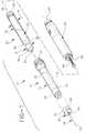
- a cartridge retainer assembly in accordance with the subject inventionis identified generally by the numeral 10 in Figs. 1-7.
- Cartridge retainer assembly 10is intended to be a part of a medication delivery pen 11 and includes elongate generally tubular body 12 with opposed proximal and distal ends 14 and 16 respectively and a cartridge receiving cavity 18 extending therebetween.
- a generally tubular needle mounting collar 20is floatably mounted to distal end 16 of body 12. Body 12 and collar 20 of cartridge retainer assembly 10 both are described in greater detail below.
- Cartridge retainer assembly 10is dimensioned and configured to receive a cartridge assembly 22 therein.
- Cartridge assembly 22includes a vial 23 with a generally tubular barrel 24 of diameter "a" with an open proximal end 26 and a distal end defined by an inwardly converging shoulder 28.
- a small diameter neck 30projects distally from shoulder 28 of barrel 24 on vial 23, and is provided with a large diameter annular bead (not shown) extending circumferentially thereabout at the extreme distal end of neck 30.
- a pierceable and resealable rubber septum 32extends completely across the open distal end defined by neck 30.
- Rubber septum 32is held in place by a metallic sleeve 34 which is crimped around the circumferential bead at the distal end of neck 30.
- Crimped metallic sleeve 34defines an approximate diameter "b" which is less than diameter "a" of body 24.
- Medicationsuch as insulin or heparin is pre-filled into vial 23 and is retained therein by a rubber stopper 36. Stopper 36 is in sliding fluid-tight engagement with the tubular wall of barrel 24. Distally directed forces on stopper 36 urge the medication from pen 11 as explained further below.
- Medication delivery pen 11further includes a prior art dosing apparatus identified generally by the numeral 38.
- Dosing apparatus 38also is generally cylindrical and includes opposed proximal and distal ends 40 and 42 respectively. Threads are disposed at distal end 42 of prior art dosing apparatus 38 for releasable threaded engagement with proximal end 14 of body 12 of cartridge retainer assembly 10, as shown in Fig. 2.
- a plunger rod 44projects distally from dosing apparatus 38 and is dimensioned to engage stopper 36 of cartridge assembly 22.
- the prior art dosing apparatus 38includes known mechanisms therein for setting a selected dose of medication to be delivered by pen 11.
- a dispensing mechanism(not shown) is operative to drive plunger rod 44 a selected distance in a distal direction for moving stopper 36 a distance that will inject the selected dose of medication from cartridge assembly 22.
- Medication delivery pen 11further includes a prior art needle assembly 46 having a metallic needle cannula 48 with opposed proximal and distal tips 50 and 52 respectively and a lumen (not shown) extending entirely therethrough.
- a cork 54is securely affixed at an intermediate position along needle cannula 48, and a cap 56 is securely affixed to cork 54.
- Cap 56 of prior art needle assembly 46includes an array of internal threads (not shown) for removable mounting to cartridge retainer assembly 10.
- prior art cartridge assemblies 22are subject to significant dimensional variation and eccentricities.
- the crimped mounting of metal sleeve 34 to neck 30can result in diametrical or axially length differences from one cartridge to the next.
- considerable eccentricities between neck 30 and body 24are likely to exist.
- Cartridge retainer assembly 10accommodates the dimensional variations and eccentricities that exist in prior art cartridge assemblies 22. More particularly, as shown in Figs. 3 and 4 body 12 of cartridge retainer assembly 10 includes a plurality of inwardly projecting supports 60 defining sections of arcs concentric with body 12. Supports 60 define an inside diameter "c" which is greater than diameter "b" defined by crimped sleeve 34 of cartridge assembly 22. Supports 60 are separated from one another by anti-rotation notches 62. An inwardly projecting annular rim 64 is defined at the extreme distal end 16 of body 12 and in spaced relation to the supports 60. Thus, an annular locking groove 65 with an axially measure thickness "d” and an inside diameter "e” is disposed intermediate supports 60 and rim 64.
- Portions of body 12 disposed proximally of supports 60define a vial receiving chamber 66 of substantially uniform diameter "f" which is slightly greater than diameter "a" of vial barrel 24. Portions of body 12 proximally of chamber 66 are of slightly larger diameter and define a recess 68 for receiving a portion of dosing apparatus 38.
- An array of internal threads 70 in recess 68engage threads on proximal end 42 of dosing apparatus 38. It is to be understood, however, that other releasable engagement means between dosing apparatus 38 and cartridge retainer assembly 10 can be provided.
- internal threadscan be formed on dosing apparatus 38 and corresponding external threads can be defined on cartridge retainer assembly 10.
- Needle mounting collar 20 of vial retainer assembly 10includes opposed proximal and distal ends 72 and 74 respectively as shown in Figs. 5 and 6.
- Proximal end 72is characterized by a plurality of anti-rotation projections 76 dimensioned and disposed for sliding engagement in notches 62 between arcuate supports 60 near distal end 16 of cartridge retainer body 12.
- Needle mounting collar 20further includes a plurality of spaced apart axially aligned slots 78 extending from proximal end 72 toward distal end 74. Slots 78 define a plurality of proximally extending resiliently deflectable fingers 80 on proximal end 72 of collar 20.
- Proximal portions of deflectable fingers 80are characterized by outwardly projecting locking ridges 82.
- Each locking ridge 82has an axially measured thickness "f" which is slightly less than the thickness "d” defined by locking groove 65 at distal end 16 of body 12.
- Opposed locking ridges 82further define an outside diameter "g" approximately equal to or slightly less than the diameter "e” defined by locking groove 65 in body 12.
- Distal end 74 of needle mounting collar 20includes a generally annular end wall 84 having an aperture 86 extending therethrough for access by proximal point 50 of needle cannula 48.
- An array of outwardly disposed threads 88is defined intermediate proximal and distal ends 72 and 74 respectively. Threads 88 are disposed and dimensioned for engaging threads on prior art needle assembly 46.
- Needle mounting collar 20 and cartridge retainer body 12are lockingly engaged with one another prior to sale of pen 11 by merely urging proximal end 72 of collar 20 into distal end 16 of body 12.
- This assemblyis carried out by first aligning anti-rotation projections 76 at proximal end 72 of collar 20 with anti-rotation notches 62 between supports 60 at distal end 16 of body 12.
- the chamfer on locking ridges 82will engage annular rim 64 of body 12 to generate radially inward deflection of fingers 80.
- locking ridges 82will pass proximally beyond rim 64. Fingers 80 will then resiliently return toward an undeflected condition to lockingly engage ridges 82 in annular locking groove 65.
- Assembly of medication delivery pen 11continues by inserting cartridge 22 into cartridge retainer assembly 10. More particularly, neck 30 and crimped metallic sleeve 34 of vial 22 are inserted in a proximal to distal direction into open proximal end 14 of body 12 of the cartridge retainer assembly. Crimped metallic sleeve 34 eventually will pass entirely through body 12, and further advancement of cartridge 22 into cartridge retainer assembly 10 will require entry of crimped metallic sleeve 34 into needle mounting collar 20. As noted above, considerable dimensional variation and eccentricities between the neck and body of prior art vials are known to exist.
- crimped metallic sleeve 34will cause collar 20 to float radially relative to body 12 into a position that conforms with any dimensional inconsistencies or eccentricities in cartridge 22. More particularly, forces generated by the distal advancement of cartridge 22 will cause resiliently deflectable fingers 80 of needle mounting collar 20 to deflect into a position that conforms with the actual location and alignment of crimped metallic sleeve 34. This floating movement will cause needle mounting collar 20 and body 12 of cartridge retainer assembly 10 to assume an eccentric alignment that conforms with an eccentrically aligned neck and body on a vial.
- Dosing apparatus 38may next be assembled to proximal end 14 of the body of cartridge retainer assembly 10 such that plunger rod 44 of dosing apparatus 38 engages stopper 26 of cartridge 22.
- Medication delivery pen 11may be used by mounting a needle assembly 46 to needle mounting collar 20 of cartridge retainer assembly 10. This mounting is achieved by moving needle assembly 46 in a proximal direction over needle mounting collar 20 until the threads (not shown) of cap 56 engage external threads 88 on needle mounting collar 20. As noted above, threads 88 of needle mounting collar 20 are spaced from the extreme distal end of needle mounting collar 20 (see Fig. 7). Thus, the initial axial advancement of cap 56 over needle mounting collar 20 will cause proximal point 50 of needle cannula 48 to pierce rubber septum 32 of cartridge 22 prior to rotational threaded engagement of needle assembly 46 with needle mounting collar 20.
- the bevel which defines proximal point 50will advance axially through septum 32 without a rotation that could tear rubber septum 32.
- cap 56engage threads 88 of needle mounting collar 20
- further advancement of needle assembly 46requires relative rotation between cap 56 and needle mounting collar 20.
- needle mounting collar 20is too small to be readily griped by the user of medication delivery pen 11, and is partly covered by cap 56.
- the relative rotationcan be achieved by rotating body 12 of cartridge retainer assembly 10.
- anti-rotation projections 76 of needle mounting collar 20are engaged in anti-rotation slots 62 which are defined between adjacent supports 60 of body 12. Hence, rotation of body 12 is transmitted to needle mounting collar 20 and enables complete rotational engagement of needle assembly 46.
- needle assembly 46is separated from needle mounting collar 20 and discarded.
- the useris encouraged to apply a disinfectant to the distal end of medication delivery pen 11.
- Disinfectantshave the potential of adversely affecting some plastic materials that could be used in a medication delivery pen.
- the two-part construction of vial retainer assembly 10enables needle mounting collar 20 to be made from a metal or other material that is resistant to disinfectants that may be applied by the user.
Landscapes
- Health & Medical Sciences (AREA)
- Vascular Medicine (AREA)
- Engineering & Computer Science (AREA)
- Anesthesiology (AREA)
- Biomedical Technology (AREA)
- Heart & Thoracic Surgery (AREA)
- Hematology (AREA)
- Life Sciences & Earth Sciences (AREA)
- Animal Behavior & Ethology (AREA)
- General Health & Medical Sciences (AREA)
- Public Health (AREA)
- Veterinary Medicine (AREA)
- Infusion, Injection, And Reservoir Apparatuses (AREA)
Description
characterised in that the engagement means is for transversely floatableengagement between said needle mounting collar and said body, whereby saidengagement means enables said cartridge retainer assembly to accommodatedimensional variations and eccentricities of said cartridge.
Claims (11)
- A cartridge retainer assembly (10) for retaining a medication cartridge (22) in amedication delivery pen, said cartridge (22) having opposed proximal (26) and distal ends, alarge diameter barrel (24) extending distally from said proximal end (26), a small diameter neck (30)extending proximally from said distal end and a converging shoulder (28) extending fromsaid barrel (24) to said neck (30), said cartridge retainer assembly (10) comprising:a generally tubular body (12) having opposed proximal and distal ends (14, 16)and being dimensioned for securely receiving said barrel (24) and said shoulder (28) of saidcartridge (22) therein; anda generally tubular needle mounting collar (20) having opposed proximal anddistal ends (72, 74) and being dimensioned for receiving said neck of said cartridgetherein, said proximal end (72) of said needle mounting collar (20) and said distal end(16) of said body (12) comprising engagement means;
characterised in that the engagement means is for transversely floatableengagement between said needle mounting collar (20) and said body (12), whereby saidengagement means enables said cartridge retainer assembly (10) to accommodatedimensional variations and eccentricities of said cartridge. - The cartridge retainer assembly (10) of claim 1, wherein the engagement meansof said needle mounting collar (20) and said body (12) further comprises means forpreventing relative rotation between said needle mounting collar (20) and said body(12).
- The cartridge retainer assembly (10) of claim 1, wherein said engagement meanscomprises means for retaining said needle mounting collar (20) and said body (12) insubstantially fixed axial positions relative to one another.
- The cartridge retainer assembly (10) of claim 1, wherein said needle mountingcollar (20) and said body (12) are formed from dissimilar materials.
- The cartridge retainer assembly (10) of claim 1, wherein said engagement meanscomprises a plurality of resiliently deflectable fingers (80) on at least one of said body(12) and said needle mounting collar (20).
- The cartridge retainer assembly (10) of claim 5, wherein each of said resilientlydeflectable fingers (80) has a locking ridge (82) thereon and wherein said engagementmeans further comprises a groove (65) engaging said locking ridges (82), saidengagement of said locking ridges (82) and said groove (65) retain said needlemounting collar (20) and said body (12) in substantially fixed axial position relative toone another.
- The cartridge retainer assembly (10) of claim 1, wherein said needle mountingcollar (20) comprises an array of external threads (88) thereon for threadedly andreleasably engaging a needle assembly, said threads (88) on said needle mounting collar(20) being spaced from said distal end (74) of said needle mounting collar (20).
- The cartridge retainer assembly (10) of claim 2, wherein said body (12) includesat least one inwardly projecting support (60) defining a distal end of said chamber (18)and including at least one anti-rotation slot (62) formed therein, an annular rib (64)spaced distally from said support (60) and defining a locking groove (65) therebetween;andsaid proximal end (72) of said collar (20) including an axially aligned anti-rotationprojection (76) engaged in said slot (62) for preventing rotation between saidneedle mounting collar (20) and said body (12), an outwardly projecting locking ridge(82) engaged in said locking groove (65) of said body (12) and a plurality of resilientlydeflectable fingers (80) defined by a corresponding plurality of axially aligned groovesextending from said proximal end to a location intermediate said ends (72, 74), saidgrooves (65) permitting deflection of said fingers (80) to accommodate dimensionalinconsistencies and eccentricities of said barrel and said neck of said cartridge.
- The cartridge retainer assembly (10) of claim 8, wherein said body (12) isformed from a transparent plastic material and wherein said needle mounting collar (20)is formed from a metallic material.
- A medication delivery pen (11) with a cartridge retainer assembly (10) of anypreceding claim.
- The pen (11) of claim 10, together with a medication cartridge (22).
Applications Claiming Priority (2)
| Application Number | Priority Date | Filing Date | Title |
|---|---|---|---|
| US08/304,953US5549575A (en) | 1994-09-13 | 1994-09-13 | Cartridge retainer assembly for medication delivery pen |
| US304953 | 1994-09-13 |
Publications (2)
| Publication Number | Publication Date |
|---|---|
| EP0701832A1 EP0701832A1 (en) | 1996-03-20 |
| EP0701832B1true EP0701832B1 (en) | 1999-02-24 |
Family
ID=23178662
Family Applications (1)
| Application Number | Title | Priority Date | Filing Date |
|---|---|---|---|
| EP95306387AExpired - LifetimeEP0701832B1 (en) | 1994-09-13 | 1995-09-12 | Cartridge retainer assembly for medication delivery pen |
Country Status (6)
| Country | Link |
|---|---|
| US (1) | US5549575A (en) |
| EP (1) | EP0701832B1 (en) |
| JP (1) | JPH0898886A (en) |
| CA (1) | CA2156696C (en) |
| DE (1) | DE69507920T2 (en) |
| ES (1) | ES2130537T3 (en) |
Families Citing this family (67)
| Publication number | Priority date | Publication date | Assignee | Title |
|---|---|---|---|---|
| US5725508A (en)* | 1994-06-22 | 1998-03-10 | Becton Dickinson And Company | Quick connect medication delivery pen |
| AU3769595A (en)* | 1995-11-09 | 1997-05-29 | Disetronic Medical Systems Ag | Injection device |
| DK0831947T3 (en) | 1996-04-02 | 2002-12-23 | Disetronic Licensing Ag | injector |
| WO1997036626A1 (en)* | 1996-04-02 | 1997-10-09 | Disetronic Licensing Ag | Injection device |
| US6413242B1 (en) | 1996-07-05 | 2002-07-02 | Disetronic Licensing Ag | Injection device for injection of liquid |
| DE59611288D1 (en)* | 1996-07-05 | 2005-12-01 | Tecpharma Licensing Ag | INJECTION DEVICE FOR INJECTING LIQUID |
| CA2213941C (en)* | 1996-09-17 | 2000-11-28 | Becton, Dickinson And Company | Non-floatable insulin cartridge holder for medication delivery pen |
| DE19717107B4 (en) | 1997-04-23 | 2005-06-23 | Disetronic Licensing Ag | System of container and drive device for a piston, which is held in the container containing a drug fluid |
| EP1841271B1 (en)* | 1997-04-24 | 2017-11-08 | Ntt Docomo, Inc. | Mobile station and network controller |
| US5931817A (en)* | 1997-09-12 | 1999-08-03 | Becton Dickinson And Company | Pen needle assembly |
| AU9202398A (en) | 1997-09-29 | 1999-04-23 | Becton Dickinson & Company | Injection device and drug cartridge for preventing cross-use of the device and drug cartridge |
| DE19740187C1 (en)* | 1997-09-12 | 1999-04-15 | Disetronic Licensing Ag | Dosing unit, e.g. for medicines |
| US6458095B1 (en)* | 1997-10-22 | 2002-10-01 | 3M Innovative Properties Company | Dispenser for an adhesive tissue sealant having a housing with multiple cavities |
| DE19755125B4 (en) | 1997-12-11 | 2006-04-20 | Tecpharma Licensing Ag | Needle protection device for injection devices |
| CZ297361B6 (en) | 1998-01-30 | 2006-11-15 | Novo Nordisk A/S | Injection syringe |
| US6017331A (en)* | 1998-02-20 | 2000-01-25 | Becton Dickinson And Company | Threaded medication cartridge |
| US6681475B2 (en) | 1998-04-20 | 2004-01-27 | Becton Dickinson And Company | Method of sealing a medical container with a plastic closure |
| US6904662B2 (en) | 1998-04-20 | 2005-06-14 | Becton, Dickinson And Company | Method of sealing a cartridge or other medical container with a plastic closure |
| US6378714B1 (en) | 1998-04-20 | 2002-04-30 | Becton Dickinson And Company | Transferset for vials and other medical containers |
| US6290679B1 (en) | 1999-05-14 | 2001-09-18 | Disetronic Licensing Ag | Device for metered administration of an injectable product |
| DE19821933C1 (en)* | 1998-05-15 | 1999-11-11 | Disetronic Licensing Ag | Device for administering an injectable product |
| DE19822031C2 (en) | 1998-05-15 | 2000-03-23 | Disetronic Licensing Ag | Auto injection device |
| CN1308550A (en)* | 1998-07-08 | 2001-08-15 | 诺沃挪第克公司 | Medication delivery device and catridge assembly for use in the same |
| JP4376338B2 (en)* | 1999-02-22 | 2009-12-02 | ベクトン・ディキンソン・アンド・カンパニー | Drug cartridge |
| TW453884B (en) | 1999-09-16 | 2001-09-11 | Novo Nordisk As | Dose setting limiter |
| EP1263387B1 (en)* | 2000-02-16 | 2004-09-15 | Haselmeier Sàrl | Method for reconstituting an injection liquid and an injection appliance for carrying out such a method |
| US6663602B2 (en) | 2000-06-16 | 2003-12-16 | Novo Nordisk A/S | Injection device |
| AU8571801A (en) | 2000-09-04 | 2002-03-22 | Forskningsct Riso | Optical amplification in coherence reflectometry |
| GB0304822D0 (en) | 2003-03-03 | 2003-04-09 | Dca Internat Ltd | Improvements in and relating to a pen-type injector |
| EP2210634A1 (en)* | 2009-01-22 | 2010-07-28 | Sanofi-Aventis Deutschland GmbH | Drug delivery device dose setting mechanism |
| GB0308267D0 (en)* | 2003-04-10 | 2003-05-14 | Dca Design Int Ltd | Improvements in and relating to a pen-type injector |
| US20040253281A1 (en)* | 2003-06-12 | 2004-12-16 | Atrium Medical Corp. | Therapeutic markings applied to tissue |
| US20050261639A1 (en)* | 2004-05-05 | 2005-11-24 | Atrium Medical Corp. | Medicated ink marker |
| US20050251152A1 (en)* | 2004-05-05 | 2005-11-10 | Atrium Medical Corp. | Illuminated medicated ink marker |
| ATE444090T1 (en) | 2004-10-21 | 2009-10-15 | Novo Nordisk As | SELECTION MECHANISM FOR A ROTARY PIN |
| WO2006089768A1 (en)* | 2005-02-28 | 2006-08-31 | Novo Nordisk A/S | A dose setting mechanism for an injection device |
| US20090043264A1 (en) | 2005-04-24 | 2009-02-12 | Novo Nordisk A/S | Injection Device |
| DK1933902T3 (en)* | 2005-09-26 | 2015-03-23 | Asante Solutions Inc | Infusion Pump WITH A DRIVE THAT HAVE AN PALLEGEME- AND CONGEST HAGE-COMBINATION |
| JP5062768B2 (en) | 2006-03-10 | 2012-10-31 | ノボ・ノルデイスク・エー/エス | INJECTION DEVICE AND METHOD FOR REPLACING CARTRIDGE OF THE DEVICE |
| CN101400394B (en) | 2006-03-10 | 2012-07-04 | 诺沃-诺迪斯克有限公司 | An injection device having a gearing arrangement |
| ATE458517T1 (en) | 2006-05-16 | 2010-03-15 | Novo Nordisk As | TRANSMISSION MECHANISM FOR AN INJECTION DEVICE |
| JP5253387B2 (en) | 2006-05-18 | 2013-07-31 | ノボ・ノルデイスク・エー/エス | Injection device with mode locking means |
| EP2109474B2 (en) | 2007-02-05 | 2019-01-30 | Novo Nordisk A/S | Injection button |
| BRPI0809265A2 (en) | 2007-03-23 | 2014-10-07 | Novo Nordisk As | INJECTION DEVICE INCLUDING A TIGHTENING NUT |
| WO2009137486A1 (en)* | 2008-05-05 | 2009-11-12 | Becton, Dickinson And Company | Drug delivery device having cartridge with enlarged distal end |
| US20100016829A1 (en)* | 2008-07-15 | 2010-01-21 | Krumme John F | Apparatus and methods for retaining a needle on a medical injector |
| US9061107B2 (en) | 2008-09-18 | 2015-06-23 | Becton, Dickinson and Comapany | Needle mounting feature for ensuring proper reconstitution sequence |
| WO2010033806A2 (en)* | 2008-09-18 | 2010-03-25 | Becton, Dickinson And Company | Needle mounting feature for ensuring proper reconstitution sequence |
| JP5600115B2 (en) | 2008-12-09 | 2014-10-01 | ベクトン・ディキンソン・アンド・カンパニー | Drug delivery system to increase lever and gear force for high pressure injection system |
| WO2010077278A1 (en) | 2008-12-09 | 2010-07-08 | Becton, Dickinson And Company | Dual-chambered drug delivery device for high pressure injections |
| CA2746164C (en) | 2008-12-09 | 2019-08-13 | Becton, Dickinson And Company | Open and closed valve medication delivery system for high pressure injections |
| US9238112B2 (en) | 2008-12-09 | 2016-01-19 | Becton, Dickinson And Company | Multi-stroke delivery pumping mechanism for a drug delivery device for high pressure injections |
| DK2355877T3 (en)* | 2008-12-12 | 2017-02-06 | Shl Group Ab | DELIVERY ELEMENT FIXING DEVICE |
| MX2012008836A (en)* | 2010-02-01 | 2012-09-07 | Sanofi Aventis Deutschland | Cartridge holder, drug delivery device and method for securing a cartridge in a cartridge holder. |
| JP5990535B2 (en)* | 2010-12-22 | 2016-09-14 | サノフィ−アベンティス・ドイチュラント・ゲゼルシャフト・ミット・ベシュレンクテル・ハフツング | Dedicated cartridge |
| JP5833230B2 (en) | 2011-05-19 | 2015-12-16 | ベクトン・ディキンソン・アンド・カンパニーBecton, Dickinson And Company | Injection device with automatic material combination function |
| CN105536108B (en)* | 2011-05-19 | 2019-02-26 | 贝克顿·迪金森公司 | Injection device with automatic material assemblage characteristic |
| JP6069351B2 (en) | 2011-12-29 | 2017-02-01 | ノボ・ノルデイスク・エー/エス | Torsion spring type automatic syringe with dial-up / dial-down administration mechanism |
| US8834449B2 (en) | 2012-01-23 | 2014-09-16 | Ikomed Technologies, Inc. | Mixing syringe |
| US9751056B2 (en) | 2012-01-23 | 2017-09-05 | Merit Medical Systems, Inc. | Mixing syringe |
| WO2013110769A2 (en)* | 2012-01-25 | 2013-08-01 | Novo Nordisk A/S | Drug delivery device with cartridge fixation feature |
| US11103640B2 (en) | 2012-02-24 | 2021-08-31 | Novo Nordisk A/S | Drug delivery device with front loading feature |
| EP2967506B1 (en)* | 2013-03-15 | 2020-04-29 | Becton, Dickinson and Company | Smart adapter for infusion devices |
| US10004845B2 (en) | 2014-04-18 | 2018-06-26 | Becton, Dickinson And Company | Split piston metering pump |
| US9416775B2 (en) | 2014-07-02 | 2016-08-16 | Becton, Dickinson And Company | Internal cam metering pump |
| RS65380B1 (en) | 2017-08-24 | 2024-04-30 | Novo Nordisk As | Glp-1 compositions and uses thereof |
| IL294520A (en) | 2020-02-18 | 2022-09-01 | Novo Nordisk As | Pharmaceutical formulations |
Family Cites Families (10)
| Publication number | Priority date | Publication date | Assignee | Title |
|---|---|---|---|---|
| FR2352555A1 (en)* | 1976-05-25 | 1977-12-23 | Egolf Georges | Medical injection syringe, esp. for local anaesthetics in dentistry - is suitable for both cartridge loading and suction filling |
| DE2915338C2 (en)* | 1979-04-14 | 1986-10-09 | Gebr. Pajunk GmbH Feingerätebau, Medizintechnik, 7716 Geisingen | Reusable spray rack |
| JPS59100433U (en)* | 1982-12-24 | 1984-07-06 | 株式会社トツプ | Syringe with cartridge inserted |
| US4973318A (en)* | 1988-02-10 | 1990-11-27 | D.C.P. Af 1988 A/S | Disposable syringe |
| GB8819977D0 (en)* | 1988-08-23 | 1988-09-21 | Medimech Ltd | Automatic injectors |
| US5085641A (en)* | 1989-07-17 | 1992-02-04 | Survival Technology, Inc. | Conveniently carried frequent use auto-injector with improved cap structure |
| DE3924830A1 (en)* | 1989-07-27 | 1991-02-07 | Vetter & Co Apotheker | SYRINGE CYLINDER FOR MEDICAL PURPOSES |
| ATE123418T1 (en)* | 1990-09-21 | 1995-06-15 | Novo Nordisk As | ADAPTER. |
| US5360410A (en)* | 1991-01-16 | 1994-11-01 | Senetek Plc | Safety syringe for mixing two-component medicaments |
| US5281198A (en)* | 1992-05-04 | 1994-01-25 | Habley Medical Technology Corporation | Pharmaceutical component-mixing delivery assembly |
- 1994
- 1994-09-13USUS08/304,953patent/US5549575A/ennot_activeExpired - Lifetime
- 1995
- 1995-08-22CACA002156696Apatent/CA2156696C/ennot_activeExpired - Fee Related
- 1995-09-12DEDE69507920Tpatent/DE69507920T2/ennot_activeExpired - Lifetime
- 1995-09-12EPEP95306387Apatent/EP0701832B1/ennot_activeExpired - Lifetime
- 1995-09-12ESES95306387Tpatent/ES2130537T3/ennot_activeExpired - Lifetime
- 1995-09-13JPJP7235821Apatent/JPH0898886A/enactivePending
Also Published As
| Publication number | Publication date |
|---|---|
| CA2156696A1 (en) | 1996-03-14 |
| CA2156696C (en) | 1999-08-17 |
| US5549575A (en) | 1996-08-27 |
| JPH0898886A (en) | 1996-04-16 |
| ES2130537T3 (en) | 1999-07-01 |
| DE69507920T2 (en) | 1999-08-19 |
| DE69507920D1 (en) | 1999-04-01 |
| EP0701832A1 (en) | 1996-03-20 |
Similar Documents
| Publication | Publication Date | Title |
|---|---|---|
| EP0701832B1 (en) | Cartridge retainer assembly for medication delivery pen | |
| US6146361A (en) | Medication delivery pen having a 31 gauge needle | |
| US8574214B2 (en) | Cartridge and needle system therefor | |
| US6648859B2 (en) | Disposable, pre-filled drug cartridge | |
| EP0990446B1 (en) | Pen needle magazine | |
| EP0549694B1 (en) | Adaptor top | |
| EP1323446B1 (en) | Syringe-type container for liquid medicine | |
| EP0697222B1 (en) | Pen needle dispenser | |
| EP1249250B1 (en) | Flexible needle assembly | |
| EP0796604B1 (en) | Syringe alignment device | |
| EP0829268A2 (en) | Non-floatable insulin cartridge holder for medication delivery pen | |
| AU2002248537A1 (en) | Kit including side firing syringe needle for preparing a drug in an injection pen cartridge | |
| WO2002076374A1 (en) | Kit including side firing syringe needle for preparing a drug in an injection pen cartridge | |
| EP3381492B1 (en) | Syringe tip cap assembly, syringe comprising such a syringe tip cap and method of sealing a syringe barrel | |
| JPH11164889A (en) | Pen needle magazine dispenser | |
| HU210361B (en) | Method for manufacturing prefilled plastic cartridge and syringe | |
| US11684727B2 (en) | Pen needle apparatus | |
| US20210251849A1 (en) | Syringe assembly and adapter member | |
| CN119768200A (en) | Improved auto-injector | |
| WO1997020586A2 (en) | Syringe |
Legal Events
| Date | Code | Title | Description |
|---|---|---|---|
| PUAI | Public reference made under article 153(3) epc to a published international application that has entered the european phase | Free format text:ORIGINAL CODE: 0009012 | |
| AK | Designated contracting states | Kind code of ref document:A1 Designated state(s):DE ES FR GB IT | |
| 17P | Request for examination filed | Effective date:19960916 | |
| 17Q | First examination report despatched | Effective date:19971204 | |
| GRAG | Despatch of communication of intention to grant | Free format text:ORIGINAL CODE: EPIDOS AGRA | |
| GRAG | Despatch of communication of intention to grant | Free format text:ORIGINAL CODE: EPIDOS AGRA | |
| GRAH | Despatch of communication of intention to grant a patent | Free format text:ORIGINAL CODE: EPIDOS IGRA | |
| GRAH | Despatch of communication of intention to grant a patent | Free format text:ORIGINAL CODE: EPIDOS IGRA | |
| GRAA | (expected) grant | Free format text:ORIGINAL CODE: 0009210 | |
| AK | Designated contracting states | Kind code of ref document:B1 Designated state(s):DE ES FR GB IT | |
| ITF | It: translation for a ep patent filed | ||
| REF | Corresponds to: | Ref document number:69507920 Country of ref document:DE Date of ref document:19990401 | |
| ET | Fr: translation filed | ||
| REG | Reference to a national code | Ref country code:ES Ref legal event code:FG2A Ref document number:2130537 Country of ref document:ES Kind code of ref document:T3 | |
| PLBE | No opposition filed within time limit | Free format text:ORIGINAL CODE: 0009261 | |
| STAA | Information on the status of an ep patent application or granted ep patent | Free format text:STATUS: NO OPPOSITION FILED WITHIN TIME LIMIT | |
| 26N | No opposition filed | ||
| REG | Reference to a national code | Ref country code:GB Ref legal event code:IF02 | |
| PGFP | Annual fee paid to national office [announced via postgrant information from national office to epo] | Ref country code:GB Payment date:20120925 Year of fee payment:18 | |
| PGFP | Annual fee paid to national office [announced via postgrant information from national office to epo] | Ref country code:ES Payment date:20120926 Year of fee payment:18 Ref country code:IT Payment date:20120924 Year of fee payment:18 Ref country code:FR Payment date:20121001 Year of fee payment:18 | |
| PGFP | Annual fee paid to national office [announced via postgrant information from national office to epo] | Ref country code:DE Payment date:20120927 Year of fee payment:18 | |
| GBPC | Gb: european patent ceased through non-payment of renewal fee | Effective date:20130912 | |
| REG | Reference to a national code | Ref country code:DE Ref legal event code:R119 Ref document number:69507920 Country of ref document:DE Effective date:20140401 | |
| REG | Reference to a national code | Ref country code:FR Ref legal event code:ST Effective date:20140530 | |
| PG25 | Lapsed in a contracting state [announced via postgrant information from national office to epo] | Ref country code:GB Free format text:LAPSE BECAUSE OF NON-PAYMENT OF DUE FEES Effective date:20130912 | |
| PG25 | Lapsed in a contracting state [announced via postgrant information from national office to epo] | Ref country code:IT Free format text:LAPSE BECAUSE OF NON-PAYMENT OF DUE FEES Effective date:20130912 Ref country code:DE Free format text:LAPSE BECAUSE OF NON-PAYMENT OF DUE FEES Effective date:20140401 Ref country code:FR Free format text:LAPSE BECAUSE OF NON-PAYMENT OF DUE FEES Effective date:20130930 | |
| REG | Reference to a national code | Ref country code:ES Ref legal event code:FD2A Effective date:20141007 | |
| PG25 | Lapsed in a contracting state [announced via postgrant information from national office to epo] | Ref country code:ES Free format text:LAPSE BECAUSE OF NON-PAYMENT OF DUE FEES Effective date:20130913 |