EP0698986B1 - Method for adaptive echo compensation - Google Patents
Method for adaptive echo compensationDownload PDFInfo
- Publication number
- EP0698986B1 EP0698986B1EP95112666AEP95112666AEP0698986B1EP 0698986 B1EP0698986 B1EP 0698986B1EP 95112666 AEP95112666 AEP 95112666AEP 95112666 AEP95112666 AEP 95112666AEP 0698986 B1EP0698986 B1EP 0698986B1
- Authority
- EP
- European Patent Office
- Prior art keywords
- signal
- filter
- step width
- value
- echo
- Prior art date
- Legal status (The legal status is an assumption and is not a legal conclusion. Google has not performed a legal analysis and makes no representation as to the accuracy of the status listed.)
- Expired - Lifetime
Links
- 238000000034methodMethods0.000titleclaimsabstractdescription21
- 230000003044adaptive effectEffects0.000titleclaimsdescription5
- 230000008878couplingEffects0.000claimsabstractdescription45
- 238000010168coupling processMethods0.000claimsabstractdescription45
- 238000005859coupling reactionMethods0.000claimsabstractdescription45
- 238000002592echocardiographyMethods0.000claimsabstractdescription20
- 230000004044responseEffects0.000claimsabstractdescription9
- 238000005259measurementMethods0.000claimsdescription7
- 230000005540biological transmissionEffects0.000claimsdescription5
- 230000005284excitationEffects0.000claimsdescription4
- 238000010606normalizationMethods0.000claimsdescription2
- 230000000717retained effectEffects0.000claimsdescription2
- 230000002123temporal effectEffects0.000abstract1
- 230000006870functionEffects0.000description8
- 230000008859changeEffects0.000description7
- 238000004891communicationMethods0.000description6
- 230000003111delayed effectEffects0.000description6
- 230000006978adaptationEffects0.000description5
- 238000010586diagramMethods0.000description5
- 230000006835compressionEffects0.000description3
- 238000007906compressionMethods0.000description3
- 238000011156evaluationMethods0.000description3
- 230000010354integrationEffects0.000description3
- 238000005070samplingMethods0.000description3
- 230000035945sensitivityEffects0.000description3
- 238000010219correlation analysisMethods0.000description2
- 230000001934delayEffects0.000description2
- 230000007613environmental effectEffects0.000description2
- 238000001914filtrationMethods0.000description2
- 230000007774longtermEffects0.000description2
- 230000007704transitionEffects0.000description2
- 238000012935AveragingMethods0.000description1
- 230000015572biosynthetic processEffects0.000description1
- 238000004364calculation methodMethods0.000description1
- 230000001276controlling effectEffects0.000description1
- 230000003247decreasing effectEffects0.000description1
- 230000001419dependent effectEffects0.000description1
- 238000013461designMethods0.000description1
- 238000001514detection methodMethods0.000description1
- 230000000694effectsEffects0.000description1
- 230000001771impaired effectEffects0.000description1
- 230000008569processEffects0.000description1
- 238000012545processingMethods0.000description1
- 230000001105regulatory effectEffects0.000description1
- 239000007787solidSubstances0.000description1
- 238000011144upstream manufacturingMethods0.000description1
Images

Classifications
- H—ELECTRICITY
- H04—ELECTRIC COMMUNICATION TECHNIQUE
- H04M—TELEPHONIC COMMUNICATION
- H04M9/00—Arrangements for interconnection not involving centralised switching
- H04M9/08—Two-way loud-speaking telephone systems with means for conditioning the signal, e.g. for suppressing echoes for one or both directions of traffic
- H04M9/082—Two-way loud-speaking telephone systems with means for conditioning the signal, e.g. for suppressing echoes for one or both directions of traffic using echo cancellers
Definitions
- the inventionrelates to a method for echo cancellation in one Transmission system in which an undesired coupling between a signal in the sending direction and a signal in the receiving direction occurs.
- Such a methodis used for technical purposes, for example in hands-free systems of telecommunication terminals, at which the acoustic coupling from the speaker to the microphone leads to a part of the received signal from the loudspeaker via the Air gap and possibly a housing to the microphone and thus to the speaker on the other side of the transmission system passes back. This part is the annoying echo of the speaker perceived.
- the size of the unwanted coupling between Loudspeaker and microphoneare determined by the type of transducer, their distance from each other, their directivity and sensitivity and the environment in which the transducers are operated, certainly.
- the Speaker-microphone coupling factoris determined from the correlation of the Microphone signal determined with the speaker signal.
- correlation analysishas the disadvantage that because of the Similarity of the speech signals incorrect decisions of the correlator are not excluded.
- the computing effortis very high large, so the correlation analysis alone is about 30% of the total Program effort required.
- the task nowis to develop an adaptive method Echo compensation to indicate that at different Ambient conditions can be used universally and with the help an integrated circuit in hands-free systems different sizes as mass commodity inexpensive is feasible.
- An FIR filteris used in a known manner used, the filter coefficients, for example, after NLMS algorithm can be determined as from the documents XP439113 and XP338371 known. This object is achieved by the one described in the first claim Process solved, the following using the example of a Echo canceller is described in a speakerphone.
- the change in filter coefficientsis used in this procedure depending on the current coupling factor between Speaker and microphone controlled.
- the Coupling factorare only suitable reception signals evaluated, that means weakly received signals excluded from the evaluation as well as local signals that occur in intercom.
- the coupling factoris below these restrictions from the ratio of the electrical signal on the microphone for the electrical signal on the speaker.
- the electrical signal on the loudspeakeris corresponding to the acoustic signal propagation time from speaker to microphone delayed, so that the ratio of corresponding in time Signals is formed.
- the delay time to be setis based on the time position the largest filter coefficient with respect to the start of the Impulse response of the FIR filter determined.
- the value of the largest filter coefficientserves as an output variable for normalization for the other filter coefficients, so that a exact representation of the filter coefficients for one by one Fixed point computer predefined range of values, for example 16 bit per sample is possible.
- the received signalsare transmitted via a high-pass filter low cutoff frequency on the FIR filter of the echo canceller given.
- the mean of the difference in the amounts of direct Microphone signal and the compensated microphone signalis constantly checked. If the mean becomes negative, it shows one Incorrect setting, a so-called overcompensation, of the Echo canceller.
- the replica of the echo signalis compared to one known solutions low number of filter coefficients achieved so that the FIR filter is also inexpensive is feasible.
- an echo cancelleris included realizable with little effort, which is very quick and very adapts exactly to different conditions and its stability with weak reception signals and with local noise signals and is retained in the case of intercom.
- Such an echo cancelleris used in hands-free systems that have a natural Enable conversation between two or more conversation partners.
- the procedureis general, i.e. also for non-acoustic ones Echo cancellation can be used.
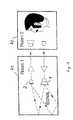
- a speakeris shown in room R2, whose language is transferred to room R1.
- the one in room R1 Loudspeaker 1sent acoustic signals partly in a microphone 2 and then reach the speaker in room 2 as acoustic echoes.
- Fig. 2shows a telephone device 3 with Speaker 1, microphone 2 and a speakerphone 4, the contains an echo canceller.
- the microphone 2is generally from surrounded by a spherical space with a certain radius the echoes can be received. 2 are different Echo generation possibilities are shown.
- Telephone device 3is coupled via the housing between speaker 1 and microphone 2, so that echoes 31 within of the housing arise.
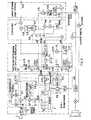
- Fig. 3shows as An essential component of an echo canceller is a finite pulse Response filter, FIR filter 5 for short, the output signal h (k) of subtracted from the echoed sample value of the microphone signal z (k) and a sample of the compensated microphone signal y (k) supplies.
- the echoes from the space around the microphone 2are described by a number N of the filter coefficients c 1 to c N of the FIR filter 5, the sampling frequency f s and the shortest distance d ak between loudspeaker 1 and microphone 2.
- the distance d akcorresponds to a minimal acoustic signal propagation time t ak between loudspeaker 1 and microphone 2, within which no echoes can occur, so that the impulse response of the system loudspeaker 1 ⁇ microphone 2 has the value zero in the interval 0 ⁇ t ⁇ t ak .
- the step size ⁇is a measure of the change in the filter coefficients c 1 to c N after a new calculation. In order to achieve a coefficient adaptation to the echo signal at all, ⁇ must be>0; furthermore, ⁇ must be ⁇ 2 in order to avoid instability and overcompensation. Overcompensation means coupling the output signal of the FIR filter 5 to the microphone signal instead of a desired negative feedback; the echoes would be amplified. If the step size ⁇ is chosen to be large, the filter coefficients c 1 to c N change very quickly, but there is a risk of overcompensation. With a small step size ⁇ , the risk of incorrect setting is lower, but it takes a longer time until the filter coefficients c 1 to c N are adapted to a change in the spatial echo.
- the filter coefficients c 1 to c Nare miscalculated a) in the case of two-way communication, that is to say both conversation partners speak simultaneously and b) during the pauses in the conversation, since adaptation is then made to the noise of the amplifier. In these cases, the FIR filter would be set so incorrectly that the return loss from loudspeaker 1 to microphone 2 would be impaired by the echo canceller.
- the filter coefficients c 1 to c Nare changed quickly in the event of changes in the impulse response, that is to say, for example, in the changed position of loudspeaker 1 or microphone 2 or in the event of greatly changed environmental conditions; they are changed more slowly if the echo canceller is set well or if measurements are uncertain.
- Thisis achieved by controlling the step size ⁇ a) as a function of the speaker-microphone coupling dlm remaining after the echo canceller, b) on the quality Q of the excitation, c) on the presence of local speech signals lokspk, d) on the presence of local ones briefly fluctuating noises lnoise and e) detection of overcompensation loss. So first ⁇ f (dlm, Q, lokspk, lnoise, loss)
- the short-term level of the microphone signal yeffis first determined from the time signal y (k) on the microphone 2 by forming the amount 5.11 and subsequent integration 5.21.
- the short-term level of the loudspeaker signal xeffis determined from the time signal x (k) on the loudspeaker 1 by forming the amount 5.1 and subsequent integration 5.2.
- the long-term mean value of the reception level reclevis determined from the time signal x (k) on the loudspeaker 1 by forming the amount 5.1 and integrating 5.12.
- the short-term level of the loudspeaker signal xeffIn order to obtain the correct assignment of the short-term level of the microphone signal yeff to the short-term level of the loudspeaker signal xeff, the short-term level of the loudspeaker signal xeff must be delayed by at least the acoustic signal propagation time t ak , so that the time delays on the way from the loudspeaker 1 to the microphone 2 and the converter delays are compensated for.
- the short-term level of the loudspeaker signal xeffis delayed by a delay circuit 5.3 and supplies the delayed signal xeffd.
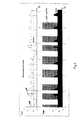
- FIG. 4shows in the lower part the time course of the coupling signal dlmfakt for a two-way situation.
- the first minimum value detector 5.13consists of a first storage and comparison circuit 5.6 and a second storage and comparison circuit 5.7 connected downstream thereof, and a counter 5.8.
- the output signal dlmalt of the first storage and comparison circuit 5.6is constantly renewed to the smaller value of dlmalt and dlmfact and thus searches for the smallest value in the time interval.
- this value dlmaltis taken over by the second storage and comparison circuit 5.7, while the output signal dlmalt of the first storage and comparison circuit 5.6 is set to the current coupling signal dlmfact in order to search again for the smallest value in the following time interval.
- the second storage and comparison circuit 5.7compares the instantaneous value of the coupling signal dlmfact with the stored output signal dlmalt of the first storage and comparison circuit 5.6.
- the second storage and comparison circuit 5.7takes over the smaller value in order to find the smallest possible value as quickly as possible.
- the output signal at least of the second storage and comparison circuit 5.7is filtered with a low-pass filter 5.9 and then provides the best estimate for the loudspeaker-microphone coupling dlm. Possible errors in the estimation of this value are reduced by averaging over time using integrators 5.2 and 5.21 and by filtering using a low-pass filter 5.9, and by evaluating the smallest coupling signal dlmfact.
- the delay ⁇ 1 of the short-term level of the loudspeaker signal xeffis set exactly by the delay circuit 5.3, the low-pass filtering can take place with a significantly higher cut-off frequency thus a faster adaptation of the estimated value to the current loudspeaker-microphone coupling dlm can be carried out.
- This filter 6can also be used to implement more complex evaluation functions for Q.
- the sampled values of the loudspeaker signal x (k)can be continuously monitored to determine whether there is a strong broadband signal, noise-like or pulse-shaped, which is used to determine the filter coefficients quickly and precisely c 1 to c N is suitable.
- a strong suggestion, for example clapping hands on one side of the conversation partner and silence on the other sidewould be particularly suitable to quickly provoke a desired setting of the echo canceller.
- the Increment ⁇only take very small values by one To avoid incorrect setting of the echo canceller. on the other hand ⁇ must not be zero, so that a change in the local acoustic The situation is still detected by the echo canceller despite intercom can be.
- German patent application P 43 05 256.8For example, a correlation between the microphone signal z (k) and the delayed time signal x (k- ⁇ ) on Loudspeaker 1 to perform at low correlation values suggest an active local speaker.
- a control signal lokspk obtained in this wayalso shows the value one that speaks locally and with the Zero value, that there is no local speaking.
- the step size ⁇ of the local noise situationcustomized.
- the local noiseis first compared to a local one Noise level estimator determined.
- Fig. 6shows the basic circuit diagram of the noise level estimator. From the compensated microphone signal y (k) is first created with an amount generator 5.11 and a Integrator 5.21 the short-term level of the microphone signal yeff certainly. This level signal is switched on via a switch 5.14 given a second minimum value detector 5.15, the principle like the already described first minimum value detector 5.13 is working. The output signal of the second minimum value detector 5.15 gives the estimated value for the via an integrator 5.16 Noise level lnoise.
- the signal-to-noise ratio of the local echodoes not deteriorate by the full amount of the noise increase, but by a smaller amount.
- the influence of the background noise on the control of the step size ⁇can be correspondingly small.
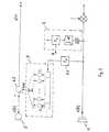
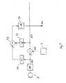
- Fig. 7shows the block diagram of a profit / loss estimator.
- the microphone signal z (k)is via a first absolute value generator 7.1 and the compensated microphone signal y (k) via a second Amount value generator 7.2 given to a subtractor 7.3, the Output signal via an integrator 7.4 the desired Gain / loss indicator with the signal loss delivers.
- the desired Gain / loss indicatorWith the signal loss delivers.
- the step size ⁇should be as large as possible to enable rapid adaptation to the new situation.
- the value for the Loudspeaker-microphone coupling dlmcan be updated.
- the echo cancelleressentially consists of the FIR filter 5, with which the echo signal h (k) is simulated from the received signal x (k) and subtracted from the microphone signal z (k) in a subtracting circuit 6.2.
- the filter coefficients c 1 ... c N of the FIR filter 5are calculated in the adaptation block 6.3.
- the variable step size ⁇ensures that the setting of the filter coefficients c 1 ... c N is carried out quickly and largely without errors.
- the step size ⁇is controlled as described above.
- the FIR filter 5is a variable delay line 6.6 upstream, the time that the sound from speaker 1 to Microphone 2 needed, bridged to the filter length N des Limit FIR filter 5 to the actual echoes.
- the output signal h 1 (k) of the FIR filter 5is first amplified with a constant factor v 1 and then in a 32 bit wide accumulator 6.7 with the time-integrated nth Power of the largest filter coefficient occurring multiplied.
- the filter coefficientsare only saved with a resolution of 16 bits in the inexpensive fixed-point computer used.
- By multiplying by the time-integrated nth power of the largest coefficient value, for example with n4, it is achieved that the coefficients of the FIR filter are dynamically optimally scaled in real time, so that for the first time with a fixed point computer advantageously essentially the same gain as is achieved with a much more expensive floating point calculator.
- the delay time ⁇ 2 to be set in the delay circuit 6.6can be determined from the position of the largest coefficient in the register.
- the compander characteristicis set.
- the microphone 2provided signals as far as they are above a setpoint compresses a uniform signal level insofar as they have the They remain unchanged and if they are below the target value the setpoint, they are further reduced in level.
- the compensated microphone signal y (k)with a bandpass 6.15 of low and high frequencies Disturbing sounds, such as impact sound and rumble, are released and thus the frequency range sensitive to the human ear filtered out.
- the compensated microphone signal y (k)the effective value yeff with the Integrator 5.21 formed.
- the time constantsare related to the behavior adapted to the human ear.
- the gain valuemust be proportional in the area of compression with increasing and disproportionately in the area of expansion decreasing input level.
- the transition of Areasis compared in a comparator 6.16 by comparing one Threshold signal us with the amount of the compensated Microphone signal
- the threshold signalis us the maximum of the estimated noise level lnoise or that with the Coupling factor dlm evaluated short-term level of the Speaker signal xeff.
Landscapes
- Engineering & Computer Science (AREA)
- Signal Processing (AREA)
- Cable Transmission Systems, Equalization Of Radio And Reduction Of Echo (AREA)
- Filters That Use Time-Delay Elements (AREA)
- Circuit For Audible Band Transducer (AREA)
Abstract
Description
Translated fromGermanDie Erfindung betrifft ein Verfahren zur Echokompensation in einemÜbertragungssystem, bei dem eine unerwünschte Kopplung zwischeneinem Signal in Senderichtung und einem Signal in Empfangsrichtungauftritt.The invention relates to a method for echo cancellation in oneTransmission system in which an undesired coupling betweena signal in the sending direction and a signal in the receiving directionoccurs.
Technische Anwendung findet ein solches Verfahren beispielsweisein Freisprecheinrichtungen von Telekommunikationsendgeräten, beidenen die akustische Kopplung vom Lautsprecher zum Mikrofon dazuführt, daß ein Teil des Empfangssignals vom Lautsprecher über dieLuftstrecke und gegebenenfalls ein Gehäuse zum Mikrofon und somitzum Sprecher auf der anderen Seite des Übertragungssystemszurückgelangt. Dieser Teil wird beim Sprecher als störendes Echowahrgenommen. Die Größe der unerwünschten Kopplung zwischenLautsprecher und Mikrofon wird durch die Art der Schallwandler,deren Abstand voneinander, deren Richtwirkung und Empfindlichkeitund von der Umgebung, in der die Schallwandler betrieben werden,bestimmt.Such a method is used for technical purposes, for examplein hands-free systems of telecommunication terminals, atwhich the acoustic coupling from the speaker to the microphoneleads to a part of the received signal from the loudspeaker via theAir gap and possibly a housing to the microphone and thusto the speaker on the other side of the transmission systempasses back. This part is the annoying echo of the speakerperceived. The size of the unwanted coupling betweenLoudspeaker and microphone are determined by the type of transducer,their distance from each other, their directivity and sensitivityand the environment in which the transducers are operated,certainly.
Es ist bekannt, mit digitalen Filtern das Echo nachzubilden unddieses vom echobehafteten Mikrofonsignal zu subtrahieren vgl.Hänsler, E: The Hands-Free Telephone Problem - An AnnotatedBibliography. Signal Processing, Band 27, Nr. 3, Juni 1992,Seite 259-271. Zur Bestimmung der Filterkoeffizienten des digitalen Filters können verschiedene Verfahren angewendet werden,beispielsweise ein nichtlinearer kanonischer mit Vorzeichenstelleversehener Algorithmus, vgl. EP 0 310 055 B1, oder der NormalizedLeast Mean Square Algorithmus, kurz NLMS-Algorithmus genannt, vgl.T. Huhn, H.-J. Jentschel: Kombination von Geräuschreduktion undEchokompensation beim Freisprechen; Nachrichtentechnik Elektronik,Berlin 43 (1993), Seite 274-280.It is known to emulate the echo with digital filters andto subtract this from the echo-laden microphone signal cf.Hansler, E: The Hands-Free Telephone Problem - An AnnotatedBibliography. Signal Processing, Volume 27, No. 3, June 1992,Page 259-271. To determine the filter coefficients of thedigital filter, various methods can be usedfor example a non-linear canonical with signprovided algorithm, cf.
Um eine brauchbare Annäherung an die Zeitfunktion der Echos zuerhalten, sind unter Umständen einige tausend Filterkoeffizientennötig. Für die praktische Realisierung ist dazu einGleitkomma- Signalprozessor mit hoher Arbeitsgeschwindigkeit undein großer Speicherplatzbedarf erforderlich, so daß dieseMöglichkeiten nur mit hohem Kostenautwand technisch verwirklichtwerden können. Die bisher bekannten Lösungen sind wegen ihresgroßen Aufwandes ungeeignet, um insbesondere die kommerziellenAnforderungen an qualitativ zufriedenstellendeFreisprecheinrichtungen, beispielsweise bei Schmalbandtelefonen,bei Schmalband- und Breitband-Bildtelefonen, inVideokonferenzstudios, für Saalbeschaltungen und für Hörgeräteerfüllen zu können.To make a useful approximation to the time function of the echoesmay have received several thousand filter coefficientsnecessary. For the practical implementation there is aFloating point signal processor with high working speed anda large space requirement is required, so thisTechnically realized possibilities only with high costscan be. The previously known solutions are because of theirgreat effort unsuitable, in particular the commercialRequirements for satisfactory qualityHands-free systems, for example in the case of narrowband telephones,for narrowband and broadband videophones, inVideo conference studios, for room circuitry and for hearing aidsto be able to fulfill.
Die Schwierigkeit des Abgleichs der Filterkoeffizienten bestehtdarin, die aktuelle Impulsantwort auf Grund der akustischenRückkopplung vom Lautsprecher über die Luftstrecke und zum Teilüber feste Körper, beispielsweise über ein Gerätegehäuse, zumMikrofon präzise zu messen, auch wenn störende Einflüsse vorhandensind. So besteht die Forderung, daß bei Einsatz einesEchokompensators gleichzeitig sehr zuverlässig unterschiedenwerden muß
Um diese Forderungen in Teilen erfüllen zu können, ist bereitsvorgeschlagen worden, die Filterkoeffizienten eines Finite ImpulseResponse Filters, kurz FIR-Filter, nach dem bekanntenNLMS-Algorithmus zu berechnen und die bei der Neuberechnung einesFilterkoeffizienten verantwortliche Schrittweite α abhängig vonder Größe des möglichen Echosignals umschaltbar zu machen, vgl.deutsche Patentanmeldung P 43 05 256.8. Um beim GegensprechenFehleinstellungen auszuschließen, wird in diesem Fall dieSchrittweite α gleich Null gesetzt, so daß eine Änderung derFilterkoeffizienten unterbleibt. Die Filterkoeffizienten werdenaber auch dann berechnet, wenn der lokale Sprecher schweigt, dasbedeutet aber, daß die Filterkoeffizienten auch bei Vorhandenseinvon sehr schwachen Eingangssignalen, zum Beispiel Rauschen, neuberechnet werden und damit eine Fehleinstellung desEchokompensators erfolgt. Es ist in dieser Anmeldung auch bereitsvorgeschlagen worden, zur Verbesserung der Echounterdrückung einenLautsprecher-Mikrofon-Kopplungsfaktor zu bestimmen und von diesemabhängig die vom Lautsprecher erzeugte Lautstärke oder dieMikrofonempfindlichkeit zu variieren. DerLautsprecher-Mikrofon-Kopplungsfaktor wird aus der Korrelation desMikrofonsignals mit dem Lautsprechersignal ermittelt. Eine solcheKorrelationsanalyse hat aber den Nachteil, daß wegen derÄhnlichkeit der Sprachsignale Fehlentscheidungen des Korrelatorsnicht ausgeschlossen sind. Außerdem ist der Rechenaufwand sehrgroß, so daß die Korrelationsanalyse allein etwa 30 % des gesamtenProgrammaufwandes benötigt.In order to be able to partially meet these requirements, is alreadyhas been proposed to filter a finite pulseResponse Filters, or FIR Filters for short, according to the well-knownNLMS algorithm to calculate and when recalculating aFilter coefficients responsible step size depending onto make the size of the possible echo signal switchable, cf.German patent application P 43 05 256.8. To talk to each otherIn this case, to exclude incorrect settingsStep size α set to zero, so that a change inFilter coefficients are omitted. The filter coefficients arebut even if the local speaker is silent, thatmeans, however, that the filter coefficients also existof very weak input signals, e.g. noise, neware calculated and thus an incorrect setting of theEcho canceller takes place. It is already in this registrationhave been proposed to improve echo cancellationSpeaker-microphone coupling factor to determine and by thisdepending on the volume generated by the loudspeaker or theVary microphone sensitivity. TheSpeaker-microphone coupling factor is determined from the correlation of theMicrophone signal determined with the speaker signal. SuchHowever, correlation analysis has the disadvantage that because of theSimilarity of the speech signals incorrect decisions of the correlatorare not excluded. In addition, the computing effort is very highlarge, so the correlation analysis alone is about 30% of the totalProgram effort required.
Es besteht nun die Aufgabe, ein Verfahren zur adaptivenEchokompensation anzugeben, das bei unterschiedlichenUmgebungsbedingungen universell einsetzbar ist und das mit Hilfeeiner integrierten Schaltung in Freisprecheinrichtungenunterschiedlicher Größe als Massenbedarfsgut kostengünstigrealisierbar ist. Dabei wird in bekannter Weise ein FIR-Filtereingesetzt, dessen Filterkoeffizienten beispielsweise nach demNLMS-Algorithmus ermittelt werden, wie aus den DokumentenXP439113 und XP338371 bekannt.Diese Aufgabe wird durch das im ersten Patentanspruch beschriebeneVerfahren gelöst, das im folgenden am Beispiel einesEchokompensators in einer Freisprecheinrichtung beschrieben wird.The task now is to develop an adaptive methodEcho compensation to indicate that at differentAmbient conditions can be used universally and with the helpan integrated circuit in hands-free systemsdifferent sizes as mass commodity inexpensiveis feasible. An FIR filter is used in a known mannerused, the filter coefficients, for example, afterNLMS algorithm can be determined as from the documentsXP439113 and XP338371 known.This object is achieved by the one described in the first claimProcess solved, the following using the example of aEcho canceller is described in a speakerphone.
Die Änderung der Filterkoeffizienten wird bei diesem Verfahrenabhängig von dem jeweiligen aktuellen Kopplungsfaktor zwischenLautsprecher und Mikrofon gesteuert. Bei der Bestimmung desKopplungsfaktors werden jedoch nur geeignete Empfangssignaleausgewertet, das bedeutet, schwach empfangene Signale werdenebenso von der Bewertung ausgeschlossen wie lokale Signale, diebeim Gegensprechen auftreten. Der Kopplungsfaktor wird unterdiesen Einschränkungen aus dem Verhältnis des elektrischen Signalsam Mikrofon zum elektrischen Signal am Lautsprecher bestimmt.Dabei wird das elektrische Signal am Lautsprecher entsprechend derakustischen Signallaufzeit vom Lautsprecher zum Mikrofonverzögert, so daß das Verhältnis von zeitlich sich entsprechendenSignalen gebildet wird.The change in filter coefficients is used in this proceduredepending on the current coupling factor betweenSpeaker and microphone controlled. When determining theCoupling factor, however, are only suitable reception signalsevaluated, that means weakly received signalsexcluded from the evaluation as well as local signals thatoccur in intercom. The coupling factor is belowthese restrictions from the ratio of the electrical signalon the microphone for the electrical signal on the speaker.The electrical signal on the loudspeaker is corresponding to theacoustic signal propagation time from speaker to microphonedelayed, so that the ratio of corresponding in timeSignals is formed.
Die einzustellende Verzögerungszeit wird aus der zeitlichen Lagedes größten Filterkoeffizienten bezüglich des Beginns derImpulsantwort des FIR-Filters ermittelt.The delay time to be set is based on the time positionthe largest filter coefficient with respect to the start of theImpulse response of the FIR filter determined.
Der Wert des größten Filterkoeffizienten dient als Ausgangsgrößezur Normierung für die weiteren Filterkoeffizienten, so daß einegenaue Darstellung der Filterkoeffizienten bei einem durch einenFestkommarechner vorgegebenen Wertebereich mit beispielsweise 16bit pro Abtastwert möglich wird.The value of the largest filter coefficient serves as an output variablefor normalization for the other filter coefficients, so that aexact representation of the filter coefficients for one by oneFixed point computer predefined range of values, for example 16bit per sample is possible.
Die empfangenen Signale werden über ein Hochpaßfilter mitniedriger Grenzfrequenz auf das FIR-Filter des Echokompensatorsgegeben.The received signals are transmitted via a high-pass filterlow cutoff frequency on the FIR filter of the echo cancellergiven.
Der Mittelwert aus der Differenz der Beträge des direktenMikrofonsignals und des kompensierten Mikrofonsignals wird ständigüberprüft. Falls der Mittelwert negativ wird, zeigt dies eineFehleinstellung, eine sogenannte Überkompensation, desEchokompensators an.The mean of the difference in the amounts of directMicrophone signal and the compensated microphone signal is constantlychecked. If the mean becomes negative, it shows oneIncorrect setting, a so-called overcompensation, of theEcho canceller.
Die Nachbildung des Echosignals wird mit einer im Vergleich zubekannten Lösungen geringen Anzahl von Filterkoeffizientenerreicht, so daß das FIR-Filter damit auch kostengünstigrealisierbar ist.The replica of the echo signal is compared to oneknown solutions low number of filter coefficientsachieved so that the FIR filter is also inexpensiveis feasible.
In den Unteransprüchen sind Gestaltungsmöglichkeiten desVerfahrens und Varianten beim Einsatz in Freisprecheinrichtungenbeschrieben.In the subclaims there are design options for theProcedures and variants when used in hands-free systemsdescribed.
Mit dem erfindungsgemäßen Verfahren ist ein Echokompensator mitgeringem Aufwand realisierbar, der sich sehr schnell und sehrgenau an unterschiedliche Bedingung anpaßt und dessen Stabilitätbei schwachen Empfangssignalen und bei lokalen Rauschsignalen undbeim Gegensprechen erhalten bleibt. Ein solcher Echokompensatorwird in Freisprecheinrichtungen eingesetzt, die eine natürlicheUnterhaltung zweier oder mehrerer Gesprächspartner ermöglichen.With the method according to the invention, an echo canceller is includedrealizable with little effort, which is very quick and veryadapts exactly to different conditions and its stabilitywith weak reception signals and with local noise signals andis retained in the case of intercom. Such an echo cancelleris used in hands-free systems that have a naturalEnable conversation between two or more conversation partners.
Das Verfahren ist allgemein, also auch bei nicht akustischerEchokompensation verwendbar.The procedure is general, i.e. also for non-acoustic onesEcho cancellation can be used.
Die Erfindung wird nachstehend an einem Ausführungsbeispielerläutert. In der dazugehörigen Zeichnung zeigen
- Fig.1
- eine Darstellung der lokalen Situation beim Freisprechen,
- Fig. 2
- ein Fernsprechendgerät mit Darstellung der Möglichkeitender Echobildung,
- Fig. 3
- eine Schaltungsanordnung eines FIR-Filters und eineSchaltungsanordnung zur Bestimmung eines Qualitätsmaßes,
- Fig. 4
- ein Zeitdiagramm zur Darstellung einer Gegensprechsituation,
- Fig. 5
- eine Schaltungsanordnung eines Schätzers der Restkopplungnach dem Echoentzerrer,
- Fig. 6
- eine Schaltungsanordnung eines Geräuschpegelschätzers,
- Fig. 7
- eine Schaltungsanordnung eines Gewinn- und Verlustschätzersund
- Fig. 8
- ein Blockschaltbild einer Freisprecheinrichtung
- Fig.1
- a representation of the local situation in hands-free mode,
- Fig. 2
- a telephone device showing the possibilities of echo formation,
- Fig. 3
- a circuit arrangement of an FIR filter and a circuit arrangement for determining a quality measure,
- Fig. 4
- a time diagram to illustrate a two-way situation,
- Fig. 5
- a circuit arrangement of an estimator of the residual coupling after the echo equalizer,
- Fig. 6
- a circuit arrangement of a noise level estimator,
- Fig. 7
- a circuit arrangement of a profit and loss estimator and
- Fig. 8
- a block diagram of a speakerphone
In Fig. 1 ist im Raum R2 ein Sprecher dargestellt, dessen Sprachein den Raum R1 übertragen wird. Die im Raum R1 von einemLautsprecher 1 gesendeten akustischen Signale gelangen zum Teil inein Mikrofon 2 und erreichen dann den Sprecher im Raum 2 alsakustische Echos. Fig. 2 zeigt ein Fernsprechendgerät 3 mitLautsprecher 1, Mikrofon 2 und einer Freisprecheinrichtung 4, dieeinen Echokompensator enthält. Das Mikrofon 2 wird allgemein voneinem kugelförmigen Raum mit einem bestimmten Radius umgeben, ausdem Echos empfangen werden können. In Fig. 2 sind unterschiedlicheEchoentstehungsmöglichkeiten dargestellt. In demFernsprechendgerät 3 erfolgt über das Gehäuse eine Kopplungzwischen Lautsprecher 1 und Mikrofon 2, so daß Echos 31 innerhalbdes Gehäuses entstehen. Weiterhin treten direkte Echos 32 über dieLuftstrecke auf und schließlich indirekte, weiter entfernte Echos33 durch Reflexionen an den Raumbegrenzungen oder an Gegenständenoder Personen innerhalb des Raumes. Bei der Bewertung dieserakustischen Situation müssen als Störungen Rauschsignale undmöglicherweise ein Gegensprechen aus dem Raum R1 gemäß Fig. 1berücksichtigt werden. Grundsätzlich ist es bekannt, Echos miteinem Echokompensator zu eliminieren. Fig. 3 zeigt alswesentlichen Bestandteil eines Echokompensators ein Finite ImpulseResponse Filter, kurz FIR-Filter 5, dessen Ausgangssignal h(k) vondem echobehafteten Abtastwert des Mikrofonsignals z(k) subtrahiert wird und einen Abtastwert des kompensierten Mikrofonsignals y(k)liefert. Um das Ausgangssignal des FIR-Filters 5 dem Echomöglichst identisch nachzubilden, wird der Abtastwert desLautsprechersignals x(k) dem FIR-Filter über eineVerzögerungsschaltung 6.6 zugeführt, so daß somit dieSignallaufzeit vom Lautsprecher 1 zum Mikrofon 2 berücksichtigtwird. Weiterhin ist in Fig. 3 ein Filter 6 zur Bestimmung einesQualitätsmaßes Q dargestellt.In Fig. 1, a speaker is shown in room R2, whose languageis transferred to room R1. The one in
Die Echos aus dem Raum um das Mikrofon 2 werden durch eine AnzahlN der Filterkoeffizienten c1 bis cN des FIR-Filters 5, derAbtastfrequenz fs und dem kürzesten Abstanddak zwischen Lautsprecher 1 und Mikrofon 2 beschrieben. DemAbstand dak entspricht eine minimale akustische Signallaufzeittak zwischen Lautsprecher 1 und Mikrofon 2, innerhalb dererkeine Echos auftreten können, so daß die Impulsantwort des SystemsLautsprecher 1 → Mikrofon 2 im Intervall 0 ≤ t < tak den WertNull hat. Die Wirkung des FIR-Filters 5 wird zeitlich begrenztdurch das Verhältnis von Anzahl N der Filterkoeffizienten undAbtastfrequenz fs,
Die Filterkoeffizienten c1 bis cN werden nach demNLMS-Algorithmus berechnet:
In Gl. 1 bedeuten
- k
- fortlaufender Index zeitlichaufeinanderfolgender Abtastwerte
- cj(k+1)
- neu zu berechnender Filterkoeffizient Nr. j zurZeit (k+1)
- cj(k)
- Filterkoeffizient Nr. j zur Zeit k
- α
- Schrittweite
- y(k) = z(k)-h(k)
- Abtastwert des Mikrofonsignals z(k) abzüglichdes Ausgangssignals h(k) zur Zeit k desFIR-
Filters 5 - x(k-j)
- Abtastwert des Lautsprechersignals zur Zeit(k-j)
- x(k-i)
- Abtastwert des Lautsprechersignals zur Zeit(k-i)
- N
- Anzahl der Filterkoeffizienten
- jak
- Grundverzögerung entsprechend tak
- j
- Index für zeitliche Verschiebung; fortlaufenderIndex der Koeffizienten cj
- i
- Index für zeitliche Verschiebung um Zeitbetragtak
- k
- consecutive index of consecutive samples
- cj (k + 1)
- filter coefficient no. j to be recalculated at the time (k + 1)
- cj (k)
- Filter coefficient No. j at time k
- α
- increment
- y (k) = z (k) -h (k)
- Sampling value of the microphone signal z (k) minus the output signal h (k) at the time k of the
FIR filter 5 - x (kj)
- Sample of the speaker signal at the time (kj)
- x (ki)
- Sample of the speaker signal at the time (ki)
- N
- Number of filter coefficients
- jak
- Basic deceleration corresponding to tak
- j
- Index for time shift; continuous index of the coefficients cj
- i
- Index for time shift by amount of time tak
Die Schrittweite α ist ein Maß für die Änderung derFilterkoeffizienten c1 bis cN nach einer Neuberechnung. Umüberhaupt eine Koeffizienten-Adaptation an das Echosignal zuerreichen, muß α > 0 sein; ferner muß α < 2 sein, um eineInstabilität und Überkompensation zu vermeiden. Überkompensationbedeutet eine Mitkopplung des Ausgangssignals des FIR-Filters 5mit dem Mikrofonsignal anstelle einer gewünschten Gegenkopplung;die Echos würden verstärkt werden. Wird die Schrittweite α großgewählt, so ändern sich zwar die Filterkoeffizienten c1 bis cNsehr schnell, aber es besteht die Gefahr einer Überkompensation.Bei kleiner Schrittweite α ist die Gefahr einer Fehleinstellunggeringer, aber es vergeht eine längere Zeit, bis dieFilterkoeffizienten c1 bis cN an eine Veränderung desRaumechos angepaßt werden.The step size α is a measure of the change in the filter coefficients c1 to cN after a new calculation. In order to achieve a coefficient adaptation to the echo signal at all, α must be>0; furthermore, α must be <2 in order to avoid instability and overcompensation. Overcompensation means coupling the output signal of the
Eine Fehlberechnung der Filterkoeffizienten c1 bis cN erfolgta) beim Gegensprechen, d.h. beide Gesprächspartner sprechengleichzeitig und b) während der Gesprächspausen, da dann auf dasRauschen des Verstärkers adaptiert wird. In diesen Fällen würdedas FIR-Filter so falsch eingestellt werden, daß dieRückhördämpfung vom Lautsprecher 1 zum Mikrofon 2 durch denEchokompensator verschlechtert wird.The filter coefficients c1 to cN are miscalculated a) in the case of two-way communication, that is to say both conversation partners speak simultaneously and b) during the pauses in the conversation, since adaptation is then made to the noise of the amplifier. In these cases, the FIR filter would be set so incorrectly that the return loss from
Erfindungsgemäß werden die Filterkoeffizienten c1 bis cN beiÄnderungen der Impulsantwort, das bedeutet beispielsweise beiveränderter Lage von Lautsprecher 1 oder Mikrofon 2 oder bei starkveränderten Umgebungsbedingungen, schnell geändert; bei guteingestelltem Echokompensator oder bei unsicheren Messungen werdensie langsamer geändert. Dies wird dadurch erreicht, daß dieSchrittweite α gesteuert wird a) in Abhängigkeit von der nach demEchokompensator verbleibenden Lautsprecher-Mikrofon-Kopplung dlm,b) von der Qualität Q der Anregung, c) vom Vorhandensein lokalerSprachsignale lokspk, d) vom Vorhandensein lokaler kurzzeitigschwankender Geräusche lnoise und e) von der Erkennung einerÜberkompensation loss. Somit wird zunächst
Mit einer solchen adaptiven Schrittweite α ist es möglich, denEchokompensator bei unterschiedlichen Umgebungsbedingungen und beiwesentlich unterschiedlichen geometrischen Anordnungen vonLautsprecher 1 und Mikrofon 2 einzusetzen. So kann dieEchokompensation sowohl bei kritischen Anordnungen, wie beimSchmalbandtelefon, als auch in Konferenzstudios eingesetzt werden.With such an adaptive step size α, it is possible toEcho canceller in different environmental conditions and atsignificantly different geometrical arrangements of
Unter Zuhilfenahme der Fig. 4 und der Fig. 5 wird nunmehr dieBestimmung der Lautsprecher-Mikrofon-Kopplung dlm und dieAbhängigkeit der Schrittweite α von derLautsprecher-Mikrofonkopplung dlm beschrieben.With the aid of FIG. 4 and FIG. 5, theDetermination of the speaker-microphone coupling dlm and theDependence of the step size α on theSpeaker microphone coupling dlm described.
Wesentlich ist, daß eine Schätzung der KopplungLautsprecher-Mikrofon dlm nach dem Echokompensator erfolgt, umbeurteilen zu können, welchen Gewinn der Echokompensator momentanerreicht hat. Deswegen wird hier präziser von der Schätzung einerRestkopplung nach dem Echokompensator vom Empfangsweg auf denSendeweg gesprochen.It is essential that an estimate of the couplingSpeaker microphone dlm after the echo canceller is made toto be able to assess the current gain of the echo cancellerhas reached. Therefore, the estimation of one becomes more precise hereResidual coupling after the echo canceller from the reception path to theSpoken.
Gemäß Fig. 5 wird zunächst aus dem Zeitsignal y(k) am Mikrofon 2durch Betragsbildung 5.11 und folgende Integration 5.21 derKurzzeitpegel des Mikrofonsignals yeff ermittelt. In gleicherWeise wird aus dem Zeitsignal x(k) am Lautsprecher 1 durchBetragsbildung 5.1 und folgende Integration 5.2 der Kurzzeitpegeldes Lautsprechersignals xeff ermittelt. Entsprechend wird aus demZeitsignal x(k) am Lautsprecher 1 durch Betragsbildung 5.1 undIntegration 5.12 der Langzeitmittelwert des Empfangspegels reclevermittelt. Um die zeitlich richtige Zuordnung des Kurzzeitpegelsdes Mikrofonsignals yeff zu dem Kurzzeitpegel desLautsprechersignals xeff zu erhalten, muß der Kurzzeitpegel desLautsprechersignals xeff mindestens um die akustischeSignallaufzeit tak verzögert werden, so daß die zeitlichenVerzögerungen auf dem Weg vom Lautsprecher 1 zum Mikrofon 2 sowiedie Verzögerungen der Wandler ausgeglichen werden. DerKurzzeitpegel des Lautsprechersignals xeff wird durch eineVerzögerungsschaltung 5.3 verzögert und liefert das verzögerteSignal xeffd. Nunmehr wird gemäß
Während eines von dem Zähler 5.8 bestimmten Zeitintervalls, wirddas Ausgangssignal dlmalt der ersten Speicher- undVergleichsschaltung 5.6 ständig auf den kleineren Wert von dlmaltund dlmfakt erneuert und sucht so den kleinsten Wert imZeitintervall. Bei Rückstellung des Zählers 5.8 wird dieser Wertdlmalt von der zweiten Speicher- und Vergleichsschaltung 5.7übernommen, während das Ausgangssignal dlmalt der ersten SpeicherundVergleichsschaltung 5.6 auf das aktuelle Kopplungssignaldlmfakt eingestellt wird, um erneut nach dem kleinsten Wert imfolgenden Zeitintervall zu suchen. Mit der zweiten Speicher- undVergleichsschaltung 5.7 wird der Momentanwert des Kopplungssignalsdlmfakt mit dem gespeicherten Ausgangssignal dlmalt der erstenSpeicher- und Vergleichsschaltung 5.6 verglichen. Die zweiteSpeicher- und Vergleichsschaltung 5.7 übernimmt jeweils denkleineren Wert, um somit möglichst schnell den kleinstmöglichen Wert mindlm zu finden. Das Ausgangssignal mindlm der zweitenSpeicher- und Vergleichsschaltung 5.7 wird mit einem Tiefpaß 5.9gefiltert und liefert dann die beste Schätzung für dieLautsprecher-Mikrofon-Kopplung dlm. Mögliche Fehler bei derSchätzung dieses Wertes werden durch die zeitlicheMittelwertbildung mittels der Integratoren 5.2 und 5.21 und durchdie Filterung mittels eines Tiefpasses 5.9 sowie durch dieAuswertung des kleinsten Kopplungssignals dlmfakt verringert. Wirddie Verzögerung τ1 des Kurzzeitpegels des Lautsprechersignalsxeff durch die Verzögerungsschaltung 5.3 exakt eingestellt, kanndie Tiefpaßfilterung mit erheblich höherer Grenzfrequenz erfolgenund
damit eine schnellere Anpassung des Schätzwertes an die aktuelleLautsprecher-Mikrofon-Kopplung dlm vorgenommen werden.During a time interval determined by the counter 5.8, the output signal dlmalt of the first storage and comparison circuit 5.6 is constantly renewed to the smaller value of dlmalt and dlmfact and thus searches for the smallest value in the time interval. When the counter 5.8 is reset, this value dlmalt is taken over by the second storage and comparison circuit 5.7, while the output signal dlmalt of the first storage and comparison circuit 5.6 is set to the current coupling signal dlmfact in order to search again for the smallest value in the following time interval. The second storage and comparison circuit 5.7 compares the instantaneous value of the coupling signal dlmfact with the stored output signal dlmalt of the first storage and comparison circuit 5.6. The second storage and comparison circuit 5.7 takes over the smaller value in order to find the smallest possible value as quickly as possible. The output signal at least of the second storage and comparison circuit 5.7 is filtered with a low-pass filter 5.9 and then provides the best estimate for the loudspeaker-microphone coupling dlm. Possible errors in the estimation of this value are reduced by averaging over time using integrators 5.2 and 5.21 and by filtering using a low-pass filter 5.9, and by evaluating the smallest coupling signal dlmfact. If the delay τ1 of the short-term level of the loudspeaker signal xeff is set exactly by the delay circuit 5.3, the low-pass filtering can take place with a significantly higher cut-off frequency
thus a faster adaptation of the estimated value to the current loudspeaker-microphone coupling dlm can be carried out.
In Abhängigkeit von der geschätzten Lautsprecher-Mikrofon-Kopplungdlm wird die in Gl. 1 enthaltene Schrittweite α nach folgenderFunktion eingestellt:
Dabei bedeuten
- dlm
- geschätzte aktuelle Lautsprecher-Mikrofon-Kopplung
- k1
- Konstante
- ∈1
- Arbeitspunkteinstellung
- p
- Exponent der Funktion
- dlm
- Estimated current speaker-microphone coupling
- k1
- constant
- ∈1
- Operating point setting
- p
- Exponent of the function
Es ist weiterhin möglich, die Einstellgeschwindigkeit und dieEinstellgenauigkeit der Filterkoeffizienten c1...cN von einemQualitätsmaß Q abhängig zu machen.It is also possible to make the setting speed and the setting accuracy of the filter coefficients c1 ... cN dependent on a quality measure Q.
Um Fehleinstellungen des Echokompensators auf ein Minimum zureduzieren, werden die Filterkoeffizienten c1...cN desFIR-Filters 5, vgl. Fig. 3, nur dann erneuert, wenn eineMindestqualität bezüglich des Empfangssignals, also der Anregungdes Lautsprechers, vorliegt, zum Beispiel wenn der Kurzzeitpegelxeff des Empfangssignals x(k) einen bestimmten Sollwert reclevüberschreitet. Das Vorzeichen der Differenz (xeff-reclev) = Vbestimmt, ob die Filterkoeffizienten c1...cN erneuert werdendürfen, falls V > 0 ist, oder ob die Filterkoeffizientenc1...cN ihren Wert behalten, falls V < 0 ist. In diesem Fallwäre Q = 1/2 (1 + sign V). Es ist durchaus möglich, für dasQualitätsmaß Q auch andere Funktionen sinngemäß zu definieren,wobei das
Qualitätsmaß Q vorteilhafterweise Werte zwischen 0 und 1 annehmenkann. Beispielsweise könnte Q die Stärke und die Signalform derAnregung bewerten, wie in Fig. 3 gezeigt, dann ist Q = f(xeffd).Für α ergibt sich nunmehr folgende Funktion:
Quality measure Q can advantageously take values between 0 and 1. For example, Q could evaluate the strength and waveform of the excitation, as shown in Figure 3, then Q = f (xeffd). The following function now results for α:
In Fig. 3 ist ein Filter 6 zur Bestimmung des Qualtitätsmaßes Qdargestellt. Mit diesem Filter 6 können auch komplexereBewertungsfunktionen für Q realisiert werden, zum Beispiel könnendie Abtastwerte des Lautsprechersignals x(k) ständig dahingehendüberwacht werden, ob ein starkes breitbandiges Signal,rauschähnlich oder impulsförmig, vorliegt, das für eine schnelleund genaue Bestimmung der Filterkoeffizienten c1 bis cNgeeignet ist. Eine starke Anregung, beispielsweise Händeklatschen,auf einer Seite der Gesprächspartner und Stille auf der anderenSeite wäre damit besonders geeignet, rasch eine gewünschteEinstellung des Echokompensators zu provozieren.3 shows a
Für den Fall, daß der lokale Sprecher aktiv ist, soll dieSchrittweite α nur sehr kleine Werte annehmen, um eineFehleinstellung des Echokompensators zu vermeiden. Andererseitsdarf α nicht Null sein, damit eine Änderung der lokalen akustischenSituation trotz Gegensprechen vom Echokompensator noch erfaßtwerden kann.In the event that the local speaker is active, theIncrement α only take very small values by oneTo avoid incorrect setting of the echo canceller. on the other handα must not be zero, so that a change in the local acousticThe situation is still detected by the echo canceller despite intercomcan be.
Es gibt mehrere Möglichkeiten, um zu erkennen, wann der lokaleSprecher spricht. In der deutschen Patentanmeldung P 43 05 256.8ist beispielsweise vorgeschlagen worden, eine Korrelation zwischendem Mikrofonsignal z(k) und dem verzögerten Zeitsignal x(k-τ) amLautsprecher 1 durchzuführen, um bei niedrigen Korrelationswertenauf einen aktiven lokalen Sprecher zu schließen.There are several ways to identify when the localSpeaker speaks. In German patent application P 43 05 256.8For example, a correlation betweenthe microphone signal z (k) and the delayed time signal x (k-τ) on
Es ist auch möglich, den Kurzzeitpegel des Mikrofonsignals yeff mitdem mit dem Kopplungsfaktor dlm gewichteten Kurzzeitpegel desEmpfangssignals xeff zu vergleichen, um zu schätzen, ob der lokaleSprecher aktiv ist. Ein so gewonnenes Steuersignal lokspk zeigt mitder Wertigkeit Eins an, daß lokal gesprochen wird und mit derWertigkeit Null, daß lokal nicht gesprochen wird.It is also possible to use the short-term level of the microphone signal yeffthe short-term level of the weighted with the coupling factor dlmCompare received signal xeff to estimate whether the localSpeaker is active. A control signal lokspk obtained in this way also showsthe value one that speaks locally and with theZero value, that there is no local speaking.
Damit läßt sich die Schrittweite wie folgt berechnen:
Ferner wird die Schrittweite α der lokalen Geräuschsituationangepaßt. Dazu wird das lokale Geräusch zunächst mit einem lokalenGeräuschpegelschätzer ermittelt. Fig. 6 zeigt das Prinzipschaltbilddes Geräuschpegelschätzers. Aus dem kompensierten Mikrofonsignaly(k) wird zunächst mit einem Betragsbildner 5.11 und einemIntegrator 5.21 der Kurzzeitpegel des Mikrofonsignals yeffbestimmt. Dieses Pegelsignal wird über einen Schalter 5.14 aufeinen zweiten Minimalwertdetektor 5.15 gegeben, der vom Prinzip herwie der bereits beschriebene erste Minimalwertdetektor 5.13 arbeitet. Das Ausgangssignal des zweiten Minimalwertdetektors 5.15ergibt über einen Integrator 5.16 den Schätzwert für denGeräuschpegel lnoise. Über den Schalter 5.14 werden dieSignalanteile aus dem Kurzzeitpegel des Mikrofonsignals yeff vonder weiteren Verarbeitung ausgeblendet, die durch einEmpfangssignal vom fernen Sprecher ein lokales Geräuschvortäuschen können. Dazu wird der gerade geschätzte Geräuschpegelmit dem mit dem Kopplungsfaktor dlm bewerteten Kurzzeitpegel desLautsprechersignals xeff verglichen. Ist der Geräuschpegel größer,so bleibt der Schalter 5.14 geschlossen.Furthermore, the step size α of the local noise situationcustomized. To do this, the local noise is first compared to a local oneNoise level estimator determined. Fig. 6 shows the basic circuit diagramof the noise level estimator. From the compensated microphone signaly (k) is first created with an amount generator 5.11 and aIntegrator 5.21 the short-term level of the microphone signal yeffcertainly. This level signal is switched on via a switch 5.14given a second minimum value detector 5.15, the principlelike the already described first minimum value detector 5.13is working. The output signal of the second minimum value detector 5.15gives the estimated value for the via an integrator 5.16Noise level lnoise. Switch 5.14 switches theSignal components from the short-term level of the microphone signal yeff vonhidden from further processing by aReceived signal from the distant speaker a local noisecan pretend. This is the noise level just estimatedwith the short-term level of the with the coupling factor dlmSpeaker signal xeff compared. If the noise level is higher,so the switch 5.14 remains closed.
Wird in einem Freisprechsystem die lokale Wiedergabelautstärkeabhängig von einer lokalen Geräuschmessung geregelt, dannverschlechtert sich der Signal-Geräuschabstand des lokalen Echosnicht um den vollen Betrag des Geräuschanstiegs, sondern um einengeringeren Betrag. Entsprechend gering kann der Einfluß desHintergrundgeräusches auf die Steuerung der Schrittweite α sein.Bezüglich der Schrittweite α soll ein geringer Geräuschpegelminnoise kaum einen Einfluß auf die Schrittweite α haben, wogegenmit zunehmendem Geräusch die Schrittweite α stetig kleiner wird.Damit wird
In praktischen Fällen ist es möglich, daß bei gut abgeglichenemEchokompensator die akustische Umgebung sich rasch ändert. Dannist die Schrittweite α sehr klein und der Echokompensator benötigteine lange Zeit, um sich erneut einzustellen. Um diesen Nachteilzu vermeiden, wird zunächst eine Einrichtung vorgesehen, mit derder durch den Echokompensator kurzzeitig erzielte Gewinn oderVerlust bestimmt werden kann. Das Ergebnis dieserGewinn/Verlust-Schätzung kann dann vorteilhafterweise dieSchrittweite α beeinflussen.In practical cases it is possible that with a well balancedEcho canceller the acoustic environment changes rapidly. Thenthe step size α is very small and the echo canceller is requireda long time to adjust again. To this disadvantageTo avoid, a facility is initially provided with thethe profit temporarily achieved by the echo canceller orLoss can be determined. The result of thisThe profit / loss estimate can then advantageously be madeAffect step size α.
Fig. 7 zeigt das Blockschaltbild eines Gewinn/Verlust-Schätzers.Das Mikrofonsignal z(k) wird über einen ersten Betragswertbildner7.1 und das kompensierte Mikrofonsignal y(k) über einen zweitenBetragswertbildner 7.2 auf einen Subtrahierer 7.3 gegeben, dessenAusgangssignal über einen Integrator 7.4 die gewünschteGewinn/Verlustanzeige mit dem Signal loss liefert. Solange dasSignal loss positiv ist, solange trägt der Echokompensator zueinem Gewinn bei. Wenn das Signal loss negativ wird, wird einedurch den Echokompensator verursachte Überkompensation angezeigt.Fig. 7 shows the block diagram of a profit / loss estimator.The microphone signal z (k) is via a first absolute value generator7.1 and the compensated microphone signal y (k) via a secondAmount value generator 7.2 given to a subtractor 7.3, theOutput signal via an integrator 7.4 the desiredGain / loss indicator with the signal loss delivers. As long as thatSignal loss is positive as long as the echo canceller continues to contributea profit on. If the loss signal becomes negative, aovercompensation caused by the echo canceller is displayed.
Von den Möglichkeiten, diese Information zur Steuerung desEchokompensators zu verwenden, wird im folgenden die Steuerung derSchrittweite α erläutert.Of the ways this information can be used to control theTo use echo canceller, the control of theStep size α explained.
Wenn das Signal loss negativ ist und damit eine Veränderung derakustischen Umgebung anzeigt, so soll die Schrittweite α möglichstgroß werden, um eine rasche Adaption an die neue Situation zuermöglichen. Dabei haben die ParameterLautsprecher-Mikrofon-Kopplung dlm, lokaler Sprecher aktiv/inaktivlokspk und lokales Geräusch vorhanden/fehlend lnoise einengeringeren Einfluß, so daß sich für die Schrittweite folgendeGleichung ergibt:
Wenn das Signal loss negativ wird, kann sofort der Wert für dieLautsprecher-Mikrofonkopplung dlm aktualisiert werden.If the signal loss becomes negative, the value for theLoudspeaker-microphone coupling dlm can be updated.
Durch die Wahl der Exponenten p, m, r wird die Empfindlichkeit derSchrittweite α von den Basisparametern festgelegt. Werden für p,m, r Zahlen kleiner eins gewählt, so wird der Einfluß deszugehörigen Parameters auf die Schrittweite α stark vermindert.Der zuvor beschriebene Echokompensator kann vorteilhafterweise miteinem Kompander kombiniert werden, der zum Zweck einer adaptiven Freisprecheinrichtung in der deutschen PatentanmeldungP 43 05 256.8 beschrieben ist und ferner in Walker, M.:Freisprechen-Ein Schritt zur natürlichen Telekommunikation,Elektrisches Nachrichtenwesen, 2. Quartal 1993, Seite 181-187.By choosing the exponents p, m, r the sensitivity of theStep size α determined by the basic parameters. Will for p,m, r numbers less than one are chosen, then the influence of theassociated parameters to the step size α greatly reduced.The echo canceller described above can advantageously be used witha compander can be combined for the purpose of an adaptiveHands-free system in the German patent applicationP 43 05 256.8 is described and also in Walker, M .:Handsfree-A step to natural telecommunications,Electrical communications, 2nd quarter 1993, pages 181-187.
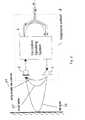
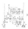
Fig. 8 zeigt ein Blockschaltbild, durch das dasFreisprechverfahren zusammenfassend beschrieben wird. Entsprechendihrer Funktion sind die einzelnen Blöcke bezeichnet mitEchokompensator, Schätzer der Restkopplung nach demEchokompensator wie bereits getrennt in Fig. 5 dargestellt undzuvor beschrieben, Kompander, lokaler Geräuschpegelschätzer sowiemit Filter zur Ebnung des Lautsprecherfrequenzganges. DerEchokompensator besteht im wesentlichen aus dem FIR-Filter 5, mitdem das Echosignal h(k) aus dem Empfangssignal x(k) nachgebildetund von dem Mikrofonsignal z(k) in einer Subtrahierschaltung 6.2subtrahiert wird. Die Filterkoeffizienten c1...cN desFIR-Filters 5 werden im Adaptionsblock 6.3 berechnet. Durch dievariierbare Schrittweite α wird erreicht, daß die Einstellung derFilterkoeffizienten c1...cN schnell und weitgehend fehlerfreierfolgt. Die Steuerung der Schrittweite α erfolgt wie obenbeschrieben.8 shows a block diagram by which the hands-free method is described in summary. According to their function, the individual blocks are designated with an echo canceller, estimators of the residual coupling after the echo canceller as already shown separately in FIG. 5 and described above, compander, local noise level estimator and with a filter for leveling the loudspeaker frequency response. The echo canceller essentially consists of the
Dem FIR-Filter 5 ist eine variable Verzögerungsleitung 6.6vorgeschaltet, die die Zeit, die der Schall vom Lautsprecher 1 zumMikrofon 2 benötigt, überbrückt, um die Filterlänge N desFIR-Filters 5 auf die eigentlichen Echos zu begrenzen.The
Zur Optimierung der Rechengenauigkeit der Filterkoeffizientenc1...cN wird das Ausgangssignal h1(k) des FIR-Filters 5zunächst mit einem konstanten Faktor v1 verstärkt undanschließend in einem 32 Bit breiten Akkumulator 6.7 mit derzeitlich integrierten n-ten Potenz des größten vorkommendenFilterkoeffizienten multipliziert. Die Filterkoeffizienten werdenbei dem verwendeten preisgünstigen Festkommarechner lediglich miteiner Auflösung von 16 Bit gespeichert. Durch die Multiplikation mit der zeitlich integrierten n-ten Potenz des größtenKoeffizientenwerts, beispielsweise mit n = 4, wird erreicht, daßdie Koeffizienten des FIR-Filters in Echtzeit dynamisch optimalskaliert werden, sodaß erstmals mit einem Festkommarechnervorteilhafterweise im wesentlichen der gleiche Gewinn wie miteinem sehr viel teuereren Gleitkommarechner erreicht wird. Damitist der Einsatz des Echokompensators sowohl beiFernsprechapparaten mit einer Rückhördämpfung zwischenLautsprecher und Mikrofon von beispielsweise -28dB als auch inStudios mit einer Rückhördämpfung von beispielsweise 8dB möglich.To optimize the computational accuracy of the filter coefficients c1 ... cN , the output signal h1 (k) of the
Aus der Lage des größten Koeffizienten im Register kann dieeinzustellende Verzögerungszeit τ2 der Verzögerungsschaltung6.6 ermittelt werden.The delay time τ2 to be set in the delay circuit 6.6 can be determined from the position of the largest coefficient in the register.
Im Block Kompander der Fig. 8 wird die Kompanderkennlinieeingestellt. Durch den Kompander werden die vom Mikrofon 2gelieferten Signale soweit sie über einem Sollwert liegen, aufeinen einheitlichen Signalpegel komprimiert, soweit sie denSollwert aufweisen bleiben sie unverändert und soweit sie unterdem Sollwert liegen, werden sie weiter im Pegel abgesenkt. Für dieAuswertung des Mikrofonpegels wird das kompensierte Mikrofonsignaly(k) mit einem Bandpaß 6.15 von nieder- und hochfrequentenStörschallen, wie Trittschall und Rumpelgeräusche, befreit unddamit der für das menschliche Ohr empfindliche Frequenzbereichherausgefiltert. Nach Betragsbildung 5.11 wird aus demkompensierten Mikrofonsignal y(k) der Effektivwert yeff mit demIntegrator 5.21 gebildet. Die Zeitkonstanten sind an das Verhaltendes menschlichen Ohres angepaßt.In the compander block of FIG. 8, the compander characteristic isset. Through the compander the
Der Verstärkungswert muß im Bereich der Kompression proportionalmit zunehmendem und im Bereich der Expansion überproportional mitabnehmendem Eingangspegel abgesenkt werden. Der Übergang derBereiche wird in einem Komparator 6.16 durch Vergleich einesSchwellensignals us mit dem Betrag des kompensierten Mikrofonsignals | y(k)| gesteuert. Dabei ist das Schwellensignal usdas Maximum des geschätzten Geräuschpegels lnoise oder der mit demKopplungsfaktor dlm bewertete Kurzzeitpegel desLautsprechersignals xeff.The gain value must be proportional in the area of compressionwith increasing and disproportionately in the area of expansiondecreasing input level. The transition ofAreas is compared in a comparator 6.16 by comparing oneThreshold signal us with the amount of the compensatedMicrophone signal | y (k) | controlled. The threshold signal is usthe maximum of the estimated noise level lnoise or that with theCoupling factor dlm evaluated short-term level of theSpeaker signal xeff.
Zur Berechnung des Verstärkungsfaktors wird zwischen den BereichenKompression und Expansion mittels eines Schalters 6.17umgeschaltet. Überschreitet der Betrag des kompensiertenMikrofonsignals | y(k)| den Schwellenwert us, was im Komparator6.16 festgestellt wird, muß die Division im Schaltungsblock 6.18mit dem Effektivwert des Lautsprechersignals xeff durchgeführtwerden. Bei kleinen Eingangssignalen, die gerade den Schwellenwertus überschreiten, erreicht der Betrag des kompensiertenMikrofonsignals | y(k)| innerhalb einer Periode nur kurz dieSchwelle, wogegen bei großen Signalen | y(k)| nur noch dieNulldurchgänge unterhalb der Schwelle liegen. Durch dienachfolgende Integration im Integrator 6.19 wird dasDivisionsergebnis gemittelt. Dadurch ergibt sich ein sanfterÜbergang zwischen den Bereichen Kompression und Expansion unddamit eine gewünschte Restdynamik von etwa 10dB.To calculate the gain factor is between the areasCompression and expansion using a switch 6.17switched. Exceeds the amount of the compensatedMicrophone signal | y (k) | the threshold us what is in the comparator6.16 is determined, the division in circuit block 6.18performed with the effective value of the speaker signal xeffbecome. For small input signals that are just the thresholdexceed us, the amount of the compensatedMicrophone signal | y (k) | only briefly within a periodThreshold, whereas with large signals | y (k) | only thatZero crossings are below the threshold. Through thesubsequent integration in integrator 6.19 willDivision result averaged. This results in a gentlerTransition between compression and expansion anda desired residual dynamic range of around 10dB.
Da der Zahlenbereich des Festkommaprozessors auf kleiner als einsbegrenzt ist, darf das Ergebnis der Division in keinem Fall größerals eins sein. Es wird ein Normierungsgröße a verwendet, die dieseBedingung für den größten vorkommenden Verstärkungswert erfüllt.Für a wird 1/1024 gewählt.Because the number range of the fixed point processor is less than onethe division's result may not be greater under any circumstancesbe as one. A standardization variable a is used, thisCondition for the largest occurring gain value met.1/1024 is selected for a.
Claims (9)
- Method of adaptive echo compensation in a transmissionsystem, containing an echo compensator with a FiniteImpulse Response filter (5), FIR filter for short, usingwhich the echoes to be expected are imitated, and theoutput signal of which is subtracted from the signal whichis affected by the echo, the filter coefficients (c1 ... cN)of the FIR filter (5) being determined according to aNormalized Least Mean Square algorithm, NLMS algorithm forshort,characterized in that
the step width (α) which is inserted in the NLMS algorithmis controlled depending on the ambient conditions of thesignal source (1) and signal sink (2) at the near end ofthe transmission system, depending on the influencingquantities which overlay and interfere with the usefulsignals, and depending on the efficiency of the echocompensator,
that from the value of the greatest filter coefficient(cmax) of the FIR filter (5), a normalisation value for theFIR filter and thus for all filter coefficients (c1 ... cN)of the FIR filter (5) is determined, in such a way that thevalues of the filter coefficients (c1 ... cN) areautomatically dynamically scaled and the value range iswithin defined limits, and
that from the time gap of the greatest filter coefficient(cmax) of the FIR filter (5) from the start of theexcitation of the signal in the outgoing direction, theshortest signal transit time (tak) from the signal source(1) to the signal sink (2) is determined, the effective time range of the echo compensator is determined from it,and this information is used to estimate the residualcoupling. - Method according to Claim 1,characterized in that thestep width (α) is determined depending on a residualcurrent coupling value (dlm), after the echo compensator,between signal source (1) and signal sink (2), in such away that the step width (α) increases as the coupling value(dlm) increases.
- Method according to Claim 1,characterized in that thestep width (α) is controlled depending on a qualitymeasurement (Q), which is determined by the difference ofthe short-term level of the signal (x(k)) of the signalsource (1) and a defined setpoint value (reclev), and thatif the sign of the difference is positive, the step width(α) becomes positive, and thus the filter coefficients(c1 ... cN) are renewed, and that if the sign of thedifference is negative, the quality measurement Q and stepwidth (α) become zero, and thus the filter coefficients(c1 ... cN) retain their values.
- Method according to Claim 1,characterized in that thestep width (α) is controlled depending on a local signalwhich is overlaid over the signal of the signal sink (2) atthe near end of the transmission system, for instancedepending on an acoustic signal of a local speaker, theshort-term level (z(k)) of the signal of the signal sink(2) being compared with the short-term level (x(k)) of thesignal of the signal source (1), and whether an additionallocal signal source is active or not being determined fromthe comparison result, and that with an increasing level of the local signal source (lokspk), the step width (α) isreduced.
- Method according to Claim 1,characterized in that thestep width (α), depending on background noise in the roomwhere the signal source (1) and signal sink (2) are, iscontrolled in such a way that with a low noise level(minnoise) the step width (α) remains unchanged, and thatas the noise level (lnoise) increases the step width (α)becomes progressively less.
- Method according to Claim 1,characterized in that thestep width (α) depends on a control value, which is formedfrom the difference of the echo-affected short-term level(z(k)) of the signal of the signal sink (2) and the short-termlevel (y(k)) of the echo-compensated signal of thesignal sink (2), that a positive sign of the differenceindicates that the echo compensator provides a gain andthus the step width (α) is retained, that a negative signof the difference indicates that the echo compensatorgenerates a loss, and that then the step width (α) isincreased, irrespective of other influencing quantities.
- Method according to Claim 1,characterized in that asthe signal source a loudspeaker (1) is used, that as thesignal sink a microphone (2) is used, and that the echocompensator is part of a hands-free device for atelecommunication terminal.
- Method according to Claim 1,characterized in that thecurrent coupling value (dlm) is determined using a firstminimum value detector (5.13), in which the smallestcoupling value (dlmalt) is determined in a first memory and comparison circuit (5.6) within a time interval which isdefined by a counter (5.8), and passed to a second memoryand comparison circuit (5.7), which in each case comparesthe momentary value of the coupling signal (dlmfakt) withthe smallest coupling value (dlmalt), which it has stored,of the first memory and comparison circuit (5.6), to findan absolutely minimum coupling value (mindlm).
- Method according to Claim 1,characterized in thatcontrol of the step width (α) and dynamic scaling of thefilter coefficients (c1 ... cN) make it possible toimplement the method using an FIR filter (5) of shortfilter length (N) and a fixed-point computer.
Applications Claiming Priority (2)
| Application Number | Priority Date | Filing Date | Title |
|---|---|---|---|
| DE4430189 | 1994-08-25 | ||
| DE4430189ADE4430189A1 (en) | 1994-08-25 | 1994-08-25 | Adaptive echo cancellation method |
Publications (3)
| Publication Number | Publication Date |
|---|---|
| EP0698986A2 EP0698986A2 (en) | 1996-02-28 |
| EP0698986A3 EP0698986A3 (en) | 1998-07-22 |
| EP0698986B1true EP0698986B1 (en) | 2003-05-28 |
Family
ID=6526557
Family Applications (1)
| Application Number | Title | Priority Date | Filing Date |
|---|---|---|---|
| EP95112666AExpired - LifetimeEP0698986B1 (en) | 1994-08-25 | 1995-08-11 | Method for adaptive echo compensation |
Country Status (4)
| Country | Link |
|---|---|
| US (1) | US5570423A (en) |
| EP (1) | EP0698986B1 (en) |
| AT (1) | ATE241883T1 (en) |
| DE (2) | DE4430189A1 (en) |
Families Citing this family (48)
| Publication number | Priority date | Publication date | Assignee | Title |
|---|---|---|---|---|
| US5734715A (en)* | 1995-09-13 | 1998-03-31 | France Telecom | Process and device for adaptive identification and adaptive echo canceller relating thereto |
| SE505152C2 (en)* | 1995-10-11 | 1997-07-07 | Ericsson Telefon Ab L M | Adaptive echo extinguishing procedure |
| DE19611548A1 (en)* | 1996-03-23 | 1997-09-25 | Sel Alcatel Ag | Method and circuit arrangement for improving the transmission properties of an echo transmission line in a telecommunications network |
| JP2000508483A (en) | 1996-04-03 | 2000-07-04 | ブリティッシュ・テレコミュニケーションズ・パブリック・リミテッド・カンパニー | Acoustic feedback correction |
| KR100200635B1 (en)* | 1996-10-28 | 1999-06-15 | 윤종용 | The echo canceller and control method therefor in video conference system |
| DE19647276A1 (en)* | 1996-11-15 | 1998-05-20 | Alsthom Cge Alcatel | Method and arrangement for adaptive echo cancellation |
| US5943645A (en)* | 1996-12-19 | 1999-08-24 | Northern Telecom Limited | Method and apparatus for computing measures of echo |
| US6160886A (en)* | 1996-12-31 | 2000-12-12 | Ericsson Inc. | Methods and apparatus for improved echo suppression in communications systems |
| DE19702117C1 (en)* | 1997-01-22 | 1997-11-20 | Siemens Ag | Telephone echo cancellation arrangement for speech input dialogue system |
| JP3361724B2 (en)* | 1997-06-11 | 2003-01-07 | 沖電気工業株式会社 | Echo canceller device |
| DE19729521B4 (en)* | 1997-07-10 | 2004-04-01 | Deutsche Telekom Ag | Method and device for suppressing noise and echo |
| GB2330746B (en)* | 1997-10-24 | 2002-07-17 | Mitel Corp | Double-talk insensitive NLMS algorithm |
| US6031908A (en)* | 1997-11-14 | 2000-02-29 | Tellabs Operations, Inc. | Echo canceller employing dual-H architecture having variable adaptive gain settings |
| US6570985B1 (en)* | 1998-01-09 | 2003-05-27 | Ericsson Inc. | Echo canceler adaptive filter optimization |
| DE19801389A1 (en) | 1998-01-16 | 1999-07-22 | Cit Alcatel | Echo cancellation method with adaptive FIR filters |
| DE19801390A1 (en)* | 1998-01-16 | 1999-07-22 | Cit Alcatel | Device and method for echo cancellation with adaptive FIR filters |
| KR100566452B1 (en)* | 1998-02-13 | 2006-03-31 | 텔레호낙티에볼라게트 엘엠 에릭슨(피유비엘) | Method and apparatus for controlling filter adaptation in noise |
| DE19815942A1 (en) | 1998-04-09 | 1999-10-14 | Cit Alcatel | Multi-channel Echo Canceller with Compander |
| DE19818609C2 (en)* | 1998-04-20 | 2000-06-15 | Deutsche Telekom Ag | Method and device for noise filtering |
| DE19850271A1 (en) | 1998-10-31 | 2000-05-04 | Alcatel Sa | Method for determining an echo coupling factor and the echo delay in a bidirectional telecommunication system |
| FR2791492B1 (en)* | 1999-03-26 | 2001-06-08 | France Telecom | ADAPTIVE IDENTIFICATION METHOD AND DEVICE, AND ADAPTIVE ECHO CANCELER USING SUCH A METHOD |
| US6415029B1 (en) | 1999-05-24 | 2002-07-02 | Motorola, Inc. | Echo canceler and double-talk detector for use in a communications unit |
| DE19925046A1 (en)* | 1999-06-01 | 2001-05-03 | Alcatel Sa | Method and device for suppressing noise and echoes |
| GB2350969B (en) | 1999-06-07 | 2003-11-05 | Ericsson Telefon Ab L M | Loudspeaker volume range control |
| DE19928045A1 (en)* | 1999-06-18 | 2000-12-28 | Alcatel Sa | Echo compensation of telecommunications system with non-linear transmission paths involves mounting suppression device in transcoder, emulating echo path non-linear component |
| US6665402B1 (en)* | 1999-08-31 | 2003-12-16 | Nortel Networks Limited | Method and apparatus for performing echo cancellation |
| CN100499390C (en)* | 1999-09-10 | 2009-06-10 | 朗迅科技公司 | Echo suppressor, echo suppression method using normalization minimum mean-square calculation |
| US6898281B1 (en)* | 2000-01-05 | 2005-05-24 | Lucent Technologies Inc. | System and method for filtering echo/NEXT signal interferrence |
| EP1475946A1 (en)* | 2000-05-12 | 2004-11-10 | Siemens Aktiengesellschaft | Method and apparatus for acoustic echo cancellation by an adaptive filter |
| DE10030926A1 (en)* | 2000-06-24 | 2002-01-03 | Alcatel Sa | Interference-dependent adaptive echo cancellation |
| DE10043064B4 (en)* | 2000-09-01 | 2004-07-08 | Dietmar Dr. Ruwisch | Method and device for eliminating loudspeaker interference from microphone signals |
| DE10119277A1 (en)* | 2001-04-20 | 2002-10-24 | Alcatel Sa | Masking noise modulation and interference noise in non-speech intervals in telecommunication system that uses echo cancellation, by inserting noise to match estimated level |
| RU2223599C2 (en)* | 2001-05-22 | 2004-02-10 | Сибирский государственный университет телекоммуникаций и информатики | Device for separating transmission signals in duplex communication system |
| US7171004B2 (en)* | 2002-08-05 | 2007-01-30 | Avaya Technology Corp. | Room acoustics echo meter for voice terminals |
| EP1432221A1 (en)* | 2002-10-22 | 2004-06-23 | Siemens Aktiengesellschaft | Low-delay echo cancellation |
| US7734034B1 (en) | 2005-06-21 | 2010-06-08 | Avaya Inc. | Remote party speaker phone detection |
| US7844453B2 (en) | 2006-05-12 | 2010-11-30 | Qnx Software Systems Co. | Robust noise estimation |
| US8335685B2 (en) | 2006-12-22 | 2012-12-18 | Qnx Software Systems Limited | Ambient noise compensation system robust to high excitation noise |
| US8107572B1 (en) | 2007-10-12 | 2012-01-31 | Harris Corporation | Communications system using adaptive filter for interference reduction |
| US8204164B1 (en) | 2007-10-12 | 2012-06-19 | Harris Corporation | Communications system using adaptive filter and selected adaptive filter taps |
| US8098781B1 (en) | 2007-10-12 | 2012-01-17 | Harris Corporation | Communications system using adaptive filter with normalization circuit |
| US7864835B2 (en)* | 2007-10-12 | 2011-01-04 | Harris Corporation | Communications system using adaptive filter and variable delay before adaptive filter taps |
| US8121236B1 (en) | 2007-10-12 | 2012-02-21 | Harris Corporation | Communications system using adaptive filter circuit using parallel adaptive filters |
| US8094763B1 (en) | 2007-10-12 | 2012-01-10 | Harris Corporation | Communications system using adaptive filter with adaptive update gain |
| US7860200B2 (en)* | 2007-10-12 | 2010-12-28 | Harris Corporation | Communications system using adaptive filter that is selected based on output power |
| US8081722B1 (en) | 2008-04-04 | 2011-12-20 | Harris Corporation | Communications system and device using simultaneous wideband and in-band narrowband operation and related method |
| CN104575509A (en)* | 2014-12-29 | 2015-04-29 | 乐视致新电子科技(天津)有限公司 | Voice enhancement processing method and device |
| EP4325824A1 (en)* | 2022-08-19 | 2024-02-21 | GN Audio A/S | Speakerphone and server device for environment acoustics determination and related methods |
Family Cites Families (22)
| Publication number | Priority date | Publication date | Assignee | Title |
|---|---|---|---|---|
| US3836734A (en)* | 1971-12-03 | 1974-09-17 | Communications Satellite Corp | Adaptive echo canceller with multi-increment gain coefficient corrections |
| NL7905577A (en)* | 1979-07-18 | 1981-01-20 | Philips Nv | DEVICE WITH A NON-RECURRENCE FILTER. |
| DE3000856A1 (en)* | 1980-01-11 | 1981-07-16 | Licentia Patent-Verwaltungs-Gmbh, 6000 Frankfurt | ADAPTIVE EQUALIZER DEVICE |
| US4852036A (en)* | 1987-01-07 | 1989-07-25 | Oki Electric Industry Co., Ltd. | Adaptive digital filter and an echo canceler incorporating the same |
| EP0310055B1 (en) | 1987-10-02 | 1994-01-12 | Advanced Micro Devices, Inc. | Adaptive echo-canceller with double-talker detection |
| AT391784B (en)* | 1987-11-25 | 1990-11-26 | Siemens Ag Oesterreich | METHOD FOR ADAPTIVELY COMPENSATING AN ECHO IN A COMMUNICATION DEVICE |
| CA1315356C (en)* | 1988-07-20 | 1993-03-30 | Seiji Miyoshi | Digital adaptive filter and method of convergence therein |
| US4912758A (en)* | 1988-10-26 | 1990-03-27 | International Business Machines Corporation | Full-duplex digital speakerphone |
| DE3840433A1 (en)* | 1988-12-01 | 1990-06-07 | Philips Patentverwaltung | Echo compensator |
| US4965822A (en)* | 1989-04-10 | 1990-10-23 | Videotelecom Corp. | Full duplex speakerphone |
| US5386472A (en)* | 1990-08-10 | 1995-01-31 | General Motors Corporation | Active noise control system |
| JPH04123621A (en)* | 1990-09-14 | 1992-04-23 | Nippon Telegr & Teleph Corp <Ntt> | Echo eraser |
| EP0483845B1 (en)* | 1990-11-01 | 1999-07-14 | Nec Corporation | Interference canceller with tap weight adaptation control using stepsize inversely proportional to the signal power level |
| EP0492647B1 (en)* | 1990-12-27 | 1997-04-23 | Nec Corporation | Adaptive filter capable of quickly identifying an unknown system |
| US5278872A (en)* | 1991-05-28 | 1994-01-11 | North American Philips Corporation | System and circuit architecture for echo cancellation and a television receiver comprising same |
| SE469677B (en)* | 1992-01-10 | 1993-08-16 | Ericsson Telefon Ab L M | DEVICE TO REDUCE THE RISK OF AN UNDESECTED PARAMETER DRIVE WITH AN ADAPTIVE FILTER USED FOR ECO-ELIMINATION |
| US5307405A (en)* | 1992-09-25 | 1994-04-26 | Qualcomm Incorporated | Network echo canceller |
| JP2654894B2 (en)* | 1992-09-30 | 1997-09-17 | 日本電信電話株式会社 | Echo canceller and method therefor |
| JP2508574B2 (en)* | 1992-11-10 | 1996-06-19 | 日本電気株式会社 | Multi-channel eco-removal device |
| US5410595A (en)* | 1992-11-12 | 1995-04-25 | Motorola, Inc. | Apparatus and method for noise reduction for a full-duplex speakerphone or the like |
| DE4305256A1 (en)* | 1993-02-20 | 1994-08-25 | Sel Alcatel Ag | Process for improving the acoustic attenuation of electroacoustic systems |
| CA2117035C (en)* | 1993-03-05 | 1997-02-18 | Akihiko Sugiyama | Method and apparatus for rapid identification of an unknown system based on an echo signal having a plurality of dispersive portions |
- 1994
- 1994-08-25DEDE4430189Apatent/DE4430189A1/ennot_activeWithdrawn
- 1995
- 1995-08-11ATAT95112666Tpatent/ATE241883T1/ennot_activeIP Right Cessation
- 1995-08-11DEDE59510700Tpatent/DE59510700D1/ennot_activeExpired - Fee Related
- 1995-08-11EPEP95112666Apatent/EP0698986B1/ennot_activeExpired - Lifetime
- 1995-08-25USUS08/519,303patent/US5570423A/ennot_activeExpired - Fee Related
Also Published As
| Publication number | Publication date |
|---|---|
| DE4430189A1 (en) | 1996-02-29 |
| DE59510700D1 (en) | 2003-07-03 |
| ATE241883T1 (en) | 2003-06-15 |
| US5570423A (en) | 1996-10-29 |
| EP0698986A3 (en) | 1998-07-22 |
| EP0698986A2 (en) | 1996-02-28 |
Similar Documents
| Publication | Publication Date | Title |
|---|---|---|
| EP0698986B1 (en) | Method for adaptive echo compensation | |
| EP0742664B1 (en) | Method for hand-free talking for a multi-channel transmission system | |
| DE69332309T2 (en) | FAILURE-PROOF OPERATING PROCEDURE IN A SPEAKER SYSTEM | |
| DE60024815T2 (en) | SYSTEM AND METHOD FOR RECOGNIZING A NEAR SPEAKER BY SPECTRUM ANALYSIS | |
| DE60108401T2 (en) | SYSTEM FOR INCREASING LANGUAGE QUALITY | |
| DE68916218T2 (en) | Computer controlled adaptable loudspeaker. | |
| DE69632851T2 (en) | Acoustic subband echo canceller | |
| DE69129497T2 (en) | RESET Echo Cancellation | |
| DE69631086T2 (en) | Subband echo compensation method using a projection algorithm | |
| DE69429947T2 (en) | echo canceller | |
| DE4305256A1 (en) | Process for improving the acoustic attenuation of electroacoustic systems | |
| DE60203282T2 (en) | PHONE UNIT | |
| DE69731573T2 (en) | Noise reduction arrangement | |
| DE68916219T2 (en) | Sound balancing arrangement for a language switchable loudspeaker. | |
| EP1103956B1 (en) | Exponential reduction of echo and noise during speech pauses | |
| DE69604901T2 (en) | SPEAKER GAIN ADJUSTMENT FOR A HANDSFREE TELECOMMUNICATION TERMINAL | |
| DE60310560T2 (en) | ECHO PROCESSING EQUIPMENT FOR ONE-CHANNEL OR MULTI-CHANNEL COMMUNICATION SYSTEMS | |
| DE69129719T2 (en) | TALKING DEVICE WITH AN ALTERNATIVE HANDS-FREE FUNCTION | |
| DE60106582T2 (en) | METHOD AND DEVICE FOR STEREO EFFECTS IN A VOIP COMMUNICATION SYSTEM | |
| EP0797339B1 (en) | Method and circuit for improving the transmission properties of a transmission link subjected to echo in a telecommunication network | |
| EP0843455B1 (en) | Method and apparatus for adaptive echo cancellation | |
| EP1126687A2 (en) | Method for coordinated echo and/or noise reduction | |
| DE19709203C2 (en) | Method for generating measuring signals for measuring systems for measuring the transmission properties of transmission links influencing one another by crosstalk in electrical communication systems, in particular hands-free devices | |
| DE4111820C2 (en) | ||
| DE19639580C2 (en) | Device for reducing acoustic echoes |
Legal Events
| Date | Code | Title | Description |
|---|---|---|---|
| PUAI | Public reference made under article 153(3) epc to a published international application that has entered the european phase | Free format text:ORIGINAL CODE: 0009012 | |
| AK | Designated contracting states | Kind code of ref document:A2 Designated state(s):AT BE CH DE ES FR GB IT LI NL SE | |
| PUAL | Search report despatched | Free format text:ORIGINAL CODE: 0009013 | |
| AK | Designated contracting states | Kind code of ref document:A3 Designated state(s):AT BE CH DE ES FR GB IT LI NL SE | |
| 17P | Request for examination filed | Effective date:19980716 | |
| GRAH | Despatch of communication of intention to grant a patent | Free format text:ORIGINAL CODE: EPIDOS IGRA | |
| GRAH | Despatch of communication of intention to grant a patent | Free format text:ORIGINAL CODE: EPIDOS IGRA | |
| GRAA | (expected) grant | Free format text:ORIGINAL CODE: 0009210 | |
| AK | Designated contracting states | Designated state(s):AT BE CH DE ES FR GB IT LI NL SE | |
| PG25 | Lapsed in a contracting state [announced via postgrant information from national office to epo] | Ref country code:NL Free format text:LAPSE BECAUSE OF FAILURE TO SUBMIT A TRANSLATION OF THE DESCRIPTION OR TO PAY THE FEE WITHIN THE PRESCRIBED TIME-LIMIT Effective date:20030528 | |
| REG | Reference to a national code | Ref country code:GB Ref legal event code:FG4D Free format text:NOT ENGLISH | |
| REG | Reference to a national code | Ref country code:CH Ref legal event code:EP | |
| GBT | Gb: translation of ep patent filed (gb section 77(6)(a)/1977) | ||
| REF | Corresponds to: | Ref document number:59510700 Country of ref document:DE Date of ref document:20030703 Kind code of ref document:P | |
| PG25 | Lapsed in a contracting state [announced via postgrant information from national office to epo] | Ref country code:AT Free format text:LAPSE BECAUSE OF NON-PAYMENT OF DUE FEES Effective date:20030811 | |
| PG25 | Lapsed in a contracting state [announced via postgrant information from national office to epo] | Ref country code:SE Free format text:LAPSE BECAUSE OF FAILURE TO SUBMIT A TRANSLATION OF THE DESCRIPTION OR TO PAY THE FEE WITHIN THE PRESCRIBED TIME-LIMIT Effective date:20030828 | |
| PG25 | Lapsed in a contracting state [announced via postgrant information from national office to epo] | Ref country code:LI Free format text:LAPSE BECAUSE OF NON-PAYMENT OF DUE FEES Effective date:20030831 Ref country code:CH Free format text:LAPSE BECAUSE OF NON-PAYMENT OF DUE FEES Effective date:20030831 Ref country code:BE Free format text:LAPSE BECAUSE OF NON-PAYMENT OF DUE FEES Effective date:20030831 | |
| PG25 | Lapsed in a contracting state [announced via postgrant information from national office to epo] | Ref country code:ES Free format text:LAPSE BECAUSE OF FAILURE TO SUBMIT A TRANSLATION OF THE DESCRIPTION OR TO PAY THE FEE WITHIN THE PRESCRIBED TIME-LIMIT Effective date:20030908 | |
| NLV1 | Nl: lapsed or annulled due to failure to fulfill the requirements of art. 29p and 29m of the patents act | ||
| BERE | Be: lapsed | Owner name:*ALCATEL SEL A.G. Effective date:20030831 | |
| ET | Fr: translation filed | ||
| PLBE | No opposition filed within time limit | Free format text:ORIGINAL CODE: 0009261 | |
| STAA | Information on the status of an ep patent application or granted ep patent | Free format text:STATUS: NO OPPOSITION FILED WITHIN TIME LIMIT | |
| REG | Reference to a national code | Ref country code:CH Ref legal event code:PL | |
| 26N | No opposition filed | Effective date:20040302 | |
| PGFP | Annual fee paid to national office [announced via postgrant information from national office to epo] | Ref country code:DE Payment date:20070822 Year of fee payment:13 | |
| PGFP | Annual fee paid to national office [announced via postgrant information from national office to epo] | Ref country code:GB Payment date:20070823 Year of fee payment:13 | |
| PGFP | Annual fee paid to national office [announced via postgrant information from national office to epo] | Ref country code:IT Payment date:20070827 Year of fee payment:13 | |
| PGFP | Annual fee paid to national office [announced via postgrant information from national office to epo] | Ref country code:FR Payment date:20070812 Year of fee payment:13 | |
| GBPC | Gb: european patent ceased through non-payment of renewal fee | Effective date:20080811 | |
| REG | Reference to a national code | Ref country code:FR Ref legal event code:ST Effective date:20090430 | |
| PG25 | Lapsed in a contracting state [announced via postgrant information from national office to epo] | Ref country code:IT Free format text:LAPSE BECAUSE OF NON-PAYMENT OF DUE FEES Effective date:20080811 Ref country code:DE Free format text:LAPSE BECAUSE OF NON-PAYMENT OF DUE FEES Effective date:20090303 | |
| PG25 | Lapsed in a contracting state [announced via postgrant information from national office to epo] | Ref country code:GB Free format text:LAPSE BECAUSE OF NON-PAYMENT OF DUE FEES Effective date:20080811 | |
| PG25 | Lapsed in a contracting state [announced via postgrant information from national office to epo] | Ref country code:FR Free format text:LAPSE BECAUSE OF NON-PAYMENT OF DUE FEES Effective date:20090430 |