EP0697661B1 - Apparatus for technical diagnosis of errors in a medical system, in particular a dentist's system - Google Patents
Apparatus for technical diagnosis of errors in a medical system, in particular a dentist's systemDownload PDFInfo
- Publication number
- EP0697661B1 EP0697661B1EP94112233AEP94112233AEP0697661B1EP 0697661 B1EP0697661 B1EP 0697661B1EP 94112233 AEP94112233 AEP 94112233AEP 94112233 AEP94112233 AEP 94112233AEP 0697661 B1EP0697661 B1EP 0697661B1
- Authority
- EP
- European Patent Office
- Prior art keywords
- module
- diagnosis
- components
- circuit boards
- printed
- Prior art date
- Legal status (The legal status is an assumption and is not a legal conclusion. Google has not performed a legal analysis and makes no representation as to the accuracy of the status listed.)
- Expired - Lifetime
Links
Images


Classifications
- G—PHYSICS
- G06—COMPUTING OR CALCULATING; COUNTING
- G06F—ELECTRIC DIGITAL DATA PROCESSING
- G06F11/00—Error detection; Error correction; Monitoring
- G06F11/22—Detection or location of defective computer hardware by testing during standby operation or during idle time, e.g. start-up testing
- G06F11/2257—Detection or location of defective computer hardware by testing during standby operation or during idle time, e.g. start-up testing using expert systems
- A—HUMAN NECESSITIES
- A61—MEDICAL OR VETERINARY SCIENCE; HYGIENE
- A61G—TRANSPORT, PERSONAL CONVEYANCES, OR ACCOMMODATION SPECIALLY ADAPTED FOR PATIENTS OR DISABLED PERSONS; OPERATING TABLES OR CHAIRS; CHAIRS FOR DENTISTRY; FUNERAL DEVICES
- A61G15/00—Operating chairs; Dental chairs; Accessories specially adapted therefor, e.g. work stands
- A61G15/02—Chairs with means to adjust position of patient; Controls therefor
- G—PHYSICS
- G16—INFORMATION AND COMMUNICATION TECHNOLOGY [ICT] SPECIALLY ADAPTED FOR SPECIFIC APPLICATION FIELDS
- G16Z—INFORMATION AND COMMUNICATION TECHNOLOGY [ICT] SPECIALLY ADAPTED FOR SPECIFIC APPLICATION FIELDS, NOT OTHERWISE PROVIDED FOR
- G16Z99/00—Subject matter not provided for in other main groups of this subclass
- A—HUMAN NECESSITIES
- A61—MEDICAL OR VETERINARY SCIENCE; HYGIENE
- A61B—DIAGNOSIS; SURGERY; IDENTIFICATION
- A61B17/00—Surgical instruments, devices or methods
- A61B2017/00681—Aspects not otherwise provided for
- A61B2017/00725—Calibration or performance testing
- G—PHYSICS
- G16—INFORMATION AND COMMUNICATION TECHNOLOGY [ICT] SPECIALLY ADAPTED FOR SPECIFIC APPLICATION FIELDS
- G16H—HEALTHCARE INFORMATICS, i.e. INFORMATION AND COMMUNICATION TECHNOLOGY [ICT] SPECIALLY ADAPTED FOR THE HANDLING OR PROCESSING OF MEDICAL OR HEALTHCARE DATA
- G16H40/00—ICT specially adapted for the management or administration of healthcare resources or facilities; ICT specially adapted for the management or operation of medical equipment or devices
- G16H40/40—ICT specially adapted for the management or administration of healthcare resources or facilities; ICT specially adapted for the management or operation of medical equipment or devices for the management of medical equipment or devices, e.g. scheduling maintenance or upgrades
Definitions
- the inventionrelates to a device for the technical diagnosis of errors in a medical, in particular a dental device according to the feature a) of claim 1.
- Medical, in particular dental, devicesgenerally comprise a large number of device components which contain one or more printed circuit boards with electronic circuits which act on electrical and / or electromechanical functional elements.
- a dental devicesuch individual components can be a patient positioning chair, a doctor and assistant element, support arms for holding and adjusting the two elements, a water unit with devices for rinsing and suctioning and for water treatment, a foot control device with which, among other things, control the functional elements mentioned and a junction box in which a supply unit and various valves for the media air and water are housed.
- the electric drill drive on the dentist elementdoes not work or does not function properly, a large number of possible errors can be considered.
- the closest causemay be the motor in the handpiece itself; However, the input voltage in the terminal box or another intervening fault location can also be the cause of the defect.
- the electrical connection of the device componentscan cause the malfunction of the engine are also in components that are not directly connected to the engine.
- the aim of the present inventionis to provide a diagnostic device with which it is possible to locate faults without cumbersome and time-consuming searching, which in the past was usually associated with dismantling or partial dismantling of the device components.
- FIG. 1shows a simplified representation in top view of a dental work station which contains the following individual device components:
- a patient support chair 1a doctor's element 2 with an operating and display part 3, a helper element 4 with an associated operating and display part 5, support arms 6 and 7 for the aforementioned elements 2 and 4, a water unit 8, a connection box 9 and a foot switch 10.
- a service computerwhich is designed here as a laptop and, as will be explained in more detail below, is connected to the device components via a cable 12.
- a PCor another suitable computer (notebook, palm top) can also be provided.
- At least some of the device components 1 to 10each contain at least one printed circuit board with electronic circuits that act on electrical and / or electromechanical functional elements.
- Electrical functional elementscan be, for example, display and / or lighting elements or also ultrasound and / or HF surgery modules.
- Electromechanical functional elementscan be electric motors and / or solenoid valves. Electric motors can be arranged as drives in both dental instruments; they can, as it were, also be arranged as adjusting motors in the device components 1, 2 and 4 and 6 and 7.
- Analog and digital sensorsare assigned to the individual device components, which act as signal generators and provide status information from the functional elements. Examples of such status information include switching states, the presence of voltages, temperatures or pressure, and compliance with specified setpoints.
- FIG. 2shows the combination of these elements in a basic illustration.
- a sensor 13is connected to a printed circuit board 14 and supplies a corresponding status signal to it.
- the flat module 14,which is supplied with the necessary voltage by a supply unit 15, activates the relevant functional element 16, e.g. a control valve or an electric drive motor.
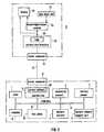
- the devicecontains special service software 20, the module of which is expediently housed in the connection box 9 (FIG. 3).
- This service softwareis used to convert the data important for diagnosis for transmission via the standard serial interface. Via the connecting cable 12 and suitable connectors 21, 22, communication with any computer that has a serial interface is possible.
- the service computer 11contains a first module 23 with a diagnostic software module, which contains a commercial troubleshooting system (e.g. Diagnostic Advisor from Emerald Intelligence, USA).
- a commercial troubleshooting systeme.g. Diagnostic Advisor from Emerald Intelligence, USA.
- This commercial troubleshooting systemis a knowledge-based system for interactive troubleshooting. It works on the basis of the guided interactive diagnosis, i.e. According to the knowledge previously entered by experts, questions must be answered by the user without using the device status / error information in online mode.
- a second module 24is connected to the first module 23 and contains a logic logic module 25.
- the module 24converts the service commands that are entered in the module 23 by experts into a corresponding command for the device components and sends this command via the standard serial interface 12 to the device components to be diagnosed.
- the status and error data returned by these device componentsare read into the aforementioned link logic 25 and processed accordingly by logically linking the status / error data.
- the componentsare advantageously communicated via a CAN bus command (Controlled Area Network).
- the printed circuit boards 14, 14 '...which have the individual device components 1 to 10, first carry out a self-test by testing the voltages of the target voltages provided on the printed circuit boards and the functions of internal circuits and also the participants on the communication bus on their Check the presence and function of the communication.
- the self-tests on the printed circuit boardsdeliver test results which are fed to the service computer 11 as an input variable via the serial interface 12.
- the test results entered into the computerare logically linked to one another in the link logic 25.
- the linkis made in accordance with a two-dimensional matrix, which is explained in more detail using the example of FIG.
- the errors registered in the individual device components 1 to 4, as well as 6, 8, and 9 based on the results of the self-test functionare read into the logic logic and linked using logical equations that are contained in the software module.
- the structure of these equationsis based on the idea that an error or an incorrect function in a device component results in a specific error pattern, i.e. in the occurrence of a certain combination of errors.
- a voltage error in the 24 volt supply voltageis reported to the diagnostic system, specifically by components 2, 3 and 8, that is to say by the doctor's device, doctor's control panel and doctor's support arm. Since the three components are physically directly connected to one another and form a unit, there is a very high probability that there is no line break in the 24-volt supply for all three components, but that the central fuse in the supply area for the unit is defective.
- the linkagecan thus in the exemplary embodiment so that if there is a 24V error in Comp. 1 and a 24V error in Comp. 6 and a 24V error in Comp. 3, then the diagnosis is made that the central fuse is defective.
- the diagnosiscan e.g. appear encrypted on the display 26 of the computer 11.
- the diagnosisis continued interactively within module 23.
- the answers given interactively via an input unit 27e.g. keyboard of the computer
- the information obtained interactivelycomplements the data already available and is included in the linking equation for the typical error pattern of the error that has occurred, which ultimately leads to a more precise localization of the error.
- an error message in the 16-volt operating voltage in the device component 1can be linked to a status message of a functional element 16 ', for example a speed error of a drive motor in the device component 1.
- An error message in the operating pressure of a medium in the device component 8can also be linked to a temperature error message in this device component.
Landscapes
- Engineering & Computer Science (AREA)
- Theoretical Computer Science (AREA)
- General Engineering & Computer Science (AREA)
- Veterinary Medicine (AREA)
- Public Health (AREA)
- Quality & Reliability (AREA)
- Life Sciences & Earth Sciences (AREA)
- Animal Behavior & Ethology (AREA)
- General Physics & Mathematics (AREA)
- Computer Hardware Design (AREA)
- Physics & Mathematics (AREA)
- General Health & Medical Sciences (AREA)
- Health & Medical Sciences (AREA)
- Test And Diagnosis Of Digital Computers (AREA)
- Accommodation For Nursing Or Treatment Tables (AREA)
- Dental Tools And Instruments Or Auxiliary Dental Instruments (AREA)
Abstract
Description
Translated fromGermanDie Erfindung betrifft eine Einrichtung zur technischen Diagnose von Fehlern in einem ärztlichen, insbesondere zahnärztlichen Gerät gemäß dem Merkmal a) des Patentanspruches 1.The invention relates to a device for the technical diagnosis of errors in a medical, in particular a dental device according to the feature a) of
Medizinische, insbesondere zahnmedizinische Geräte umfassen in der Regel eine Vielzahl von Gerätekomponenten, die eine oder mehrere Flachbaugruppen mit elektronischen Schaltkreisen enthalten, welche auf elektrische und/oder elektromechanische Funktionselemente einwirken. Bei einem zahnärztlichen Gerät können solche Einzelkomponenten sein ein Patientenlagerungsstuhl, ein Arzt- und Helferinnenelement, Tragarme zur Halterung und Verstellung der beiden Elemente, eine Wassereinheit mit Einrichtungen zum Spülen und Saugen sowie zur Wasseraufbereitung, eine Fußsteuereinrichtung, mit der sich u.a. die genannten Funktionselemente ansteuern lassen sowie ein Anschlußkasten, indem eine Versorgungseinheit sowie diverse Ventile für die Medien Luft und Wasser untergebracht sind.Medical, in particular dental, devices generally comprise a large number of device components which contain one or more printed circuit boards with electronic circuits which act on electrical and / or electromechanical functional elements. In the case of a dental device, such individual components can be a patient positioning chair, a doctor and assistant element, support arms for holding and adjusting the two elements, a water unit with devices for rinsing and suctioning and for water treatment, a foot control device with which, among other things, control the functional elements mentioned and a junction box in which a supply unit and various valves for the media air and water are housed.
Für den Servicefachmann ist es bei der Vielzahl von Möglichkeiten schwierig, auftretende Fehler relativ rasch zu finden und zu beheben.With the multitude of possibilities, it is difficult for the service specialist to find and correct errors that occur relatively quickly.
Wenn z.B. der elektrische Bohrantrieb beim Arztelement nicht oder nicht einwandfrei funktioniert, so kann dafür eine Vielzahl von Fehlermöglichkeiten in Frage kommen. Als nächstliegende Ursache kann der Motor im Handstück selbst defekt sein; es kann jedoch auch die Eingangsspannung im Anschlußkasten oder eine andere, dazwischenliegende Störstelle die Ursache für den Defekt sein. Durch die elektrische Verknüpfung der Gerätekomponenten kann die Ursache für das Nichtfunktionieren des Motors auch in Bauteilen liegen, die nicht direkt mit dem Motor in Verbindung stehen.If, for example, the electric drill drive on the dentist element does not work or does not function properly, a large number of possible errors can be considered. The closest cause may be the motor in the handpiece itself; However, the input voltage in the terminal box or another intervening fault location can also be the cause of the defect. The electrical connection of the device components can cause the malfunction of the engine are also in components that are not directly connected to the engine.
Ziel der vorliegenden Erfindung ist es, eine Diagnoseeinrichtung zu schaffen, mit der es möglich ist, Fehler ohne umständliches und zeitaufwendiges Suchen, welches nach bisheriger Art meist mit einem Zerlegen bzw. Teilzerlegen der Gerätekomponenten verbunden war, lokalisieren zu können.The aim of the present invention is to provide a diagnostic device with which it is possible to locate faults without cumbersome and time-consuming searching, which in the past was usually associated with dismantling or partial dismantling of the device components.
Das gestellte Ziel wird durch die Merkmale b) bis h) des Patentanspruchs 1 gelöst.The object is achieved by the features b) to h) of
Der Service-Rechner kann in vorteilhafter Ausgestaltung der Erfindung integraler Bestandteil der Einrichtung und einer der Geräte-Komponenten zugeordnet sein; vorteilhaft kann es auch sein, den Service-Rechner extern der Geräte-Komponenten anzuordnen.
Figur 1 zeigt einen zahnärztlichen ArbeitsplatzFigur 2 zeigt eine Prinzipdarstellung der Verknüpfung der Elemente einer GerätekomponenteFigur 3 zeigt eine schematische Übersicht einer Ausführungs form der ErfindungFigur 4 zeigt ein Beispiel für die logische Verknüpfung der Testergebnisse.
- Figure 1 shows a dental workplace
- Figure 2 shows a schematic diagram of the linkage of the elements of a device component
- Figure 3 shows a schematic overview of an embodiment of the invention
- Figure 4 shows an example of the logical linking of the test results.
Ein Ausführungsbeispiel der Erfindung wird nachfolgend anhand der Zeichnungen näher erläutert.An embodiment of the invention is explained below with reference to the drawings.
Die Figur 1 zeigt in einer vereinfachten Darstellung in der Draufsicht einen zahnärztlichen Arbeitsplatz, der folgende Geräte-Einzelkomponenten enthält:FIG. 1 shows a simplified representation in top view of a dental work station which contains the following individual device components:
Einen Patientenlagerungsstuhl 1, ein Arztelement 2 mit einem Bedien- und Anzeigeteil 3, ein Helferinnenelement 4 mit zugeordnetem Bedien- und Anzeigeteil 5, Tragarme 6 und 7 für die vorgenannten Elemente 2 und 4, eine Wassereinheit 8, einen Anschlußkasten 9 und einen Fußschalter 10.A
Mit 11 ist ein Sevice-Rechner bezeichnet, der hier als Laptop ausgebildet ist und, wie nachfolgend noch näher erläutert, über ein Kabel 12 mit den Geräte-Komponenten verbunden ist. Anstelle des Laptop kann auch ein PC oder ein anderer geeigneter Rechner (Notebook, Palmtop) vorgesehen sein.11 denotes a service computer, which is designed here as a laptop and, as will be explained in more detail below, is connected to the device components via a
Zumindest einige der Gerätekomponenten 1 bis 10 enthalten jeweils mindestens eine Flachbaugruppe mit elektronischen Schaltkreisen, die auf elektrische und/oder elektromechanische Funktionselemente einwirken. Elektrische Funktionselemente können beispielsweise Anzeige- und/oder Beleuchtungselemente oder auch Ultraschall- und/oder HF-Chirurgiebausteine sein. Elektromechanische Funktionselemente können Elektromotore und/oder Magnetventile sein. Elektromotore können als Antriebe sowohl in zahnärztlichen Instrumenten angeordnet sein; sie können gleichsam auch als Verstellmotore in den Gerätekomponenten 1, 2 und 4 sowie 6 und 7 angeordnet sein.At least some of the
Den einzelnen Gerätekomponenten sind analoge und digitale Sensoren zugeordnet, die als Signalgeber wirken und Statusinformationen von den Funktionselementen liefern. Beispiele für solche Statusinformationen sind, Schaltzustände, das Vorhandensein von Spannungen, Temperaturen oder Druck, sowie das Einhalten vorgegebener Sollwerte aufzuzeigen.Analog and digital sensors are assigned to the individual device components, which act as signal generators and provide status information from the functional elements. Examples of such status information include switching states, the presence of voltages, temperatures or pressure, and compliance with specified setpoints.
Die Figur 2 zeigt in einer Prinzipdarstellung die Verknüpfung dieser Elemente. Ein Sensor 13 ist mit einer Flachbaugruppe 14 verbunden und liefert an diese ein entsprechendes Statussignal. Die Flachbaugruppe 14, welche von einer Versorgungseinheit 15 mit der notwendigen Spannung versorgt wird, aktiviert das betreffende Funktionselement 16, z.B. ein Steuerventil oder einen Elektroantriebsmotor.FIG. 2 shows the combination of these elements in a basic illustration. A
Aus Figur 3 ist ersichtlich, daß sämtliche Flachbaugruppen 14, 14' über einen seriellen Kommunikations-Bus 17 miteinander kommunizieren. Im Ausführungsbeispiel ist angenommen, daß nicht sämtliche Einzelgerätekomponenten 1 bis 10 über den Kommunikations-Bus 17 verbunden sind, sondern nur die Komponenten 1 bis 4, 6, 8 und 9, die Flachbaugruppen aufweisen, welche auf elektrische und/oder elektromechanische Funktionselemente einwirken.It can be seen from FIG. 3 that all of the printed
Die Einrichtung enthält eine spezielle Service-Software 20, deren Baustein zweckmäßigerweise im Anschlußkasten 9 untergebracht ist (Fig. 3). Diese Service-Software dient dazu, die für die Diagnose wichtigen Daten für die Übertragung über die serielle Standardschnittstelle zu konvertieren. Über das Verbindungskabel 12 und geeignete Anschlußstecker 21, 22 ist somit eine Kommunikation mit einem beliebigen Rechner, der eine serielle Schnittstelle hat, möglich.The device contains
Der Service-Rechner 11 enthält ein erstes Modul 23 mit einem Diagnose-Software-Baustein, der ein kommerzielles Fehlersuchsystem (z.B. Diagnostic Advisor der Firma Emerald Intelligence, USA) enthält. Dieses kommerzielle Fehlersuchsystem ist ein wissensbasiertes System für eine interaktive Fehlersuche. Es arbeitet auf der Basis der geführten interaktiven Diagnose, d.h. gemäß dem von Fachexperten zuvor eingegebenen Wissen sind vom Benutzer Fragen zu beantworten, und zwar ohne Ausnutzung der Geräte-Status-/Fehlerinformationen im On-line-Betrieb.The
Mit dem ersten Modul 23 ist ein zweites Modul 24 verbunden, welches einen Verknüpfungslogik-Baustein 25 enthält. Das Modul 24 nimmt die Umsetzung von Servicebefehlen, die in dem Modul 23 von Fachexperten eingegeben werden, in einen entsprechenden Befehl für die Geräte-Komponenten vor und sendet diesen Befehl über die serielle Standardschnittstelle 12 an die zu diagnostizierenden Gerätekomponenten. Die von diesen Gerätekomponenten zurückgesandten Status- und Fehlerdaten werden in die vorerwähnte Verknüpfungslogik 25 eingelesen und durch logische Verknüpfung der Zustands-/Fehlerdaten entsprechend aufbereitet. Vorteilhafterweise erfolgt die Kommunikation der Komponenten über einen CAN-Bus-Befehl (Controlled Area Network).A
Die Fehlerdiagnose läuft wie folgt ab:The error diagnosis runs as follows:
Die Flachbaugruppen 14, 14' ..., die die einzelnen Gerätekomponenten 1 bis 10 aufweisen, führen zunächst Selbsttest durch, indem sie die Spannungen der auf den Flachbaugruppen vorgesehenen Sollspannungen sowie die Funktionen interner Schaltkreise testen und außerdem die Teilnehmer am Kommunikations-Bus auf deren Vorhandensein und Funktion in bezug auf die Kommunikation überprüfen.The printed
Die Selbsttests auf den Flachbaugruppen liefern Testergebnisse, die über die serielle Schnittstelle 12 als Eingangsgröße dem Service-Rechner 11 zugeführt werden. Die in den Rechner eingegebenen Testergebnisse werden in der Verknüpfungslogik 25 logisch miteinander verknüpft. Die Verknüpfung erfolgt dabei entsprechend einer zweidimensionalen Matrix, die am Beispiel der Figur 4 näher erläutert wird.The self-tests on the printed circuit boards deliver test results which are fed to the
Die in den einzelnen Geräte-Komponenten 1 bis 4, sowie 6, 8, und 9 aufgrund der Ergebnisse der Selbsttestfunktion registrierten Fehler werden in die Verknüpfungslogik eingelesen und über logische Gleichungen, die im Sofware-Baustein enthalten sind, verknüpft. Der Aufbau dieser Gleichungen basiert auf dem Gedanken, daß sich ein Fehler bzw. eine fehlerhafte Funktion in einer Geräte-Komponente in einem bestimmten Fehlerbild, d.h. im Auftreten einer bestimmten Kombination von Fehlern äußert.The errors registered in the
Im Ausführungsbeispiel nach Fig.4 wird dem Diagnose-System ein Spannungsfehler in der 24-Volt Versorgungsspannung gemeldet, und zwar jeweils von den Komponenten 2,3 und 8 , also von Arztgerät, Arzt-Bedienpaneel und Arzt-Tragarm. Da die drei Komponenten physikalisch direkt miteinander verbunden sind und eine Einheit bilden, ist die Wahrscheinlichkeit sehr hoch, daß nicht eine Leitungsunterbrechung der 24-Volt-Versorgung bei allen drei Komponenten vorliegt, sondern daß die zentrale Sicherung im Versorgungsbereich für die Einheit defekt ist. Die Verknüpfung kann im Ausführungsbeispiel also so sein, daß, wenn bei Komp. 1 ein 24V Fehler und bei Komp. 6 ein 24V Fehler und bei Komp. 3 ein 24V Fehler vorliegt, dann die Diagnose gegeben wird, daß die Zentralsicherung defekt ist.In the exemplary embodiment according to FIG. 4, a voltage error in the 24 volt supply voltage is reported to the diagnostic system, specifically by
Die Diagnose kann z.B. verschlüsselt am Display 26 des Rechners 11 aufscheinen.The diagnosis can e.g. appear encrypted on the
Der Vorteil der Verknüpfung dieser Testergebnisse besteht darin, daß im aufgezeigten Falle die Spannungsversorgungswege der einzelnen Komponenten nicht der Reihe nach überprüft werden müssen, bevor man letztlich dann feststellt, daß die zentrale Sicherung defekt ist.The advantage of linking these test results is that, in the case shown, the voltage supply paths of the individual components do not have to be checked in sequence before one finally determines that the central fuse is defective.
Bei einer ausreichenden Lokalisierung des Fehlers wird eine entsprechende Anweisung direkt an den Bildschirm gegeben. Ist der Fehler nicht ausreichend lokalisiert, können Statusinformationen von Funktionselementen der einzelnen Geräte-Komponenten, z.B Magnetventile, Lampen oder Motoren, abgefragt werden. Diese Daten dienen sodann als zusätzliche Informationen für eine erneut zu startende Diagnose.If the fault is localized sufficiently, a corresponding instruction is given directly to the screen. If the fault is not localized sufficiently, status information of functional elements of the individual device components, e.g. solenoid valves, lamps or motors, can be queried. This data then serves as additional information for a diagnosis to be restarted.
Ist auch bis jetzt noch keine ausreichende Lokalisierung des Fehlers gegeben, so wird die Diagnose interaktiv innerhalb des Moduls 23 fortgesetzt. Die interaktiv über eine Eingabeeinheit 27 (z.B. Tastatur des Rechners) gegebenen Antworten fließen in die Verknüpfungslogik 25 zurück und werden dort erneut so lange verknüpft, bis eine eindeutige Fehlerdiagnose gegeben ist. Die interaktiv erhaltenen Informationen ergänzen dabei die bereits vorliegenden Daten und gehen in die Verknüpfungsgleichung für das typische Fehlerbild des aufgetretenen Fehlers ein was schließlich im Ergebnis zu einer genaueren Lokalisierung des Fehlers führt.If the fault has not yet been sufficiently localized, the diagnosis is continued interactively within
Neben dem obengenannten Ausführungsbeispiel einer Fehlerdiagnose mit einer Fehlerursache im Bereich der 24 Volt Versorgungsspannung gilt Entsprechendes für die Verknüpfung von Fehlern unterschiedlicher Arten, z.B. fehlerhafte Schaltzustände, Betriebsdrücke, Temperaturen usw., wie dies in Figur 4 angedeutet ist. Danach kann beispielsweise eine Fehlermeldung in der 16-Volt-Betriebsspannung in der Geräte-Komponente 1 mit einer Statusmeldung eines Funktionselementes 16', z.B. mit einem Drehzahlfehler eines Antriebsmotors in der Geräte-Komponente 1, verknüpft werden. Ebenso kann eine Fehlermeldung im Betriebsdruck eines Mediums in der Geräte-Komponente 8 (Wassereinheit) mit einer Temperatur-Fehlermeldung in dieser Geräte-Komponente verknüpft werden.In addition to the above-mentioned exemplary embodiment of a fault diagnosis with a fault cause in the range of the 24 volt supply voltage The same applies correspondingly to the linking of errors of different types, for example faulty switching states, operating pressures, temperatures, etc., as is indicated in FIG. 4. Then, for example, an error message in the 16-volt operating voltage in the
Claims (4)
- Device for the technical diagnosis of errors in a medical, in particular a dental, apparatus,
characterised by the following features:a) the apparatus contains a plurality of components (1 to 10) which contain printed-circuit boards (14, 14', ...) with electronic circuits which act upon electrical and/or electromechanical functional elements (16, 16', ...),b) the printed-circuit boards (14, 14', ...) communicate with each other by way of a serial communications bus (17),c) associated with the components (1 to 10) there are analog and digital signal transmitters (13, 13', ...), the signals of which act as an input variable on the printed-circuit boards,d) the printed-circuit boards (14, 14', ...) contain means for carrying out self-tests, as they test the voltages on the printed-circuit boards and also the functions of internal circuits and check the parties on the communications bus to check that they are present and functioning correctly with regard to communication,e) the self-tests supply test results which are fed as input variables to a service computer (11),f) for the transmission of the data to the service computer (11) means (20) are provided that convert the data for transmission by way of a standard interface,g) the service computer (11) contains a first module (23), which renders possible interactive, user input-based error diagnosis off-line, and a second module (24) which establishes a connection between the first module (23) and the apparatus-components (1 to 10) in order to render possible on-line diagnosis with the first module (23),h) the second module (24) contains a logic element (25) which combines the test results together in a logic operation and produces a diagnosis result which, given sufficient localization, appears on a display (26) and which, if the diagnosis which is displayed is not yet sufficiently accurate, is returned to the first module (23) and there processed further in an interactive manner, with answers given in an interactive manner flowing back into the logic element (25) and there undergoing a logic operation once again for so long until an unambiguous error diagnosis results. - Device according to claim 1, characterised in that the service computer (11) is an integral part of one of the apparatus-components (1 to 10), advantageously of the operator and display panel (3) which is associated with the attendant.
- Device according to claim 1, characterised in that the service computer (11) is a mobile data-processing unit.
- Device according to claim 3, characterised in that the computer (11) is connected to the standard interface of one of the apparatus-components (1 to 10) by way of a plug-in connection cable (12).
Priority Applications (4)
| Application Number | Priority Date | Filing Date | Title |
|---|---|---|---|
| EP94112233AEP0697661B1 (en) | 1994-08-04 | 1994-08-04 | Apparatus for technical diagnosis of errors in a medical system, in particular a dentist's system |
| DE59404641TDE59404641D1 (en) | 1994-08-04 | 1994-08-04 | Device for the technical diagnosis of errors in a medical, in particular a dental device |
| DK94112233TDK0697661T3 (en) | 1994-08-04 | 1994-08-04 | Device for the technical diagnosis of errors in a medical device, especially a dental instrument |
| US08/510,313US5812397A (en) | 1994-08-04 | 1995-08-02 | Apparatus for technical diagnosis of errors in a medical/dental apparatus |
Applications Claiming Priority (1)
| Application Number | Priority Date | Filing Date | Title |
|---|---|---|---|
| EP94112233AEP0697661B1 (en) | 1994-08-04 | 1994-08-04 | Apparatus for technical diagnosis of errors in a medical system, in particular a dentist's system |
Publications (2)
| Publication Number | Publication Date |
|---|---|
| EP0697661A1 EP0697661A1 (en) | 1996-02-21 |
| EP0697661B1true EP0697661B1 (en) | 1997-11-19 |
Family
ID=8216176
Family Applications (1)
| Application Number | Title | Priority Date | Filing Date |
|---|---|---|---|
| EP94112233AExpired - LifetimeEP0697661B1 (en) | 1994-08-04 | 1994-08-04 | Apparatus for technical diagnosis of errors in a medical system, in particular a dentist's system |
Country Status (4)
| Country | Link |
|---|---|
| US (1) | US5812397A (en) |
| EP (1) | EP0697661B1 (en) |
| DE (1) | DE59404641D1 (en) |
| DK (1) | DK0697661T3 (en) |
Families Citing this family (34)
| Publication number | Priority date | Publication date | Assignee | Title |
|---|---|---|---|---|
| US6256643B1 (en) | 1998-03-10 | 2001-07-03 | Baxter International Inc. | Systems and methods for storing, retrieving, and manipulating data in medical processing devices |
| EP0822405A3 (en)* | 1996-07-30 | 2004-07-07 | Bayer Corporation | Electronics system for a hematology analytical instrument |
| IL121348A0 (en)* | 1997-07-21 | 1998-04-05 | Bio Rad Lab Israel Inc | System and method for device monitoring |
| JP2001525940A (en)* | 1998-03-10 | 2001-12-11 | バクスター インターナショナル インコーポレイテッド | System and method for monitoring and analyzing the operation of a medical processing device |
| DE19904090C2 (en)* | 1999-02-02 | 2003-06-05 | Wolf Gmbh Richard | Method and device for the automatic control and management of medical devices and systems |
| EP1235510A2 (en)* | 2000-03-23 | 2002-09-04 | Koninklijke Philips Electronics N.V. | Remote diagnostics for a medical imaging system |
| US6757714B1 (en)* | 2000-07-28 | 2004-06-29 | Axeda Systems Operating Company, Inc. | Reporting the state of an apparatus to a remote computer |
| US7117239B1 (en) | 2000-07-28 | 2006-10-03 | Axeda Corporation | Reporting the state of an apparatus to a remote computer |
| DE10046096C2 (en)* | 2000-09-18 | 2003-03-27 | Siemens Ag | Device for ensuring an optimized error handling in complex systems |
| US8108543B2 (en) | 2000-09-22 | 2012-01-31 | Axeda Corporation | Retrieving data from a server |
| DE10047552B4 (en)* | 2000-09-22 | 2007-01-04 | Siemens Ag | Medical device |
| US7185014B1 (en) | 2000-09-22 | 2007-02-27 | Axeda Corporation | Retrieving data from a server |
| US7149792B1 (en) | 2000-11-20 | 2006-12-12 | Axeda Corporation | Device registration mechanism |
| JP4590128B2 (en)* | 2001-05-18 | 2010-12-01 | 株式会社モリタ製作所 | Functional module type dental medical device, functional module for this medical device, dental medical device and medical functional module unit using this functional module |
| DE10139020A1 (en)* | 2001-08-08 | 2003-03-13 | W & H Dentalwerk Buermoos Ges | Method for control and monitoring of a treatment system, especially a medical or dental system, involves linking instruments and control units via a bi-directional bus that allows exchange of state and operational data |
| US7254601B2 (en) | 2001-12-20 | 2007-08-07 | Questra Corporation | Method and apparatus for managing intelligent assets in a distributed environment |
| US7178149B2 (en) | 2002-04-17 | 2007-02-13 | Axeda Corporation | XML scripting of soap commands |
| DE10219166B4 (en)* | 2002-04-29 | 2005-11-24 | Heribert Schmid | Medical treatment device |
| DE10303720B4 (en)* | 2003-01-30 | 2004-12-09 | Siemens Ag | Test system for medical systems |
| US7966418B2 (en) | 2003-02-21 | 2011-06-21 | Axeda Corporation | Establishing a virtual tunnel between two computer programs |
| GB2402747B (en)* | 2003-06-14 | 2007-05-09 | Desmond Bryan Mills | A medical device including a self test system |
| CN1905851B (en)* | 2004-01-27 | 2010-11-17 | Xo卡雷公司 | Dental Business Operating System |
| US7230520B2 (en)* | 2004-05-03 | 2007-06-12 | Dell Products L.P. | Method and apparatus for RF access to system ID and fault information |
| US20060252010A1 (en)* | 2005-05-09 | 2006-11-09 | Sunnen Gerard V | Sodium chloride pad for treatment of dental conditions |
| US8370479B2 (en) | 2006-10-03 | 2013-02-05 | Axeda Acquisition Corporation | System and method for dynamically grouping devices based on present device conditions |
| US8065397B2 (en) | 2006-12-26 | 2011-11-22 | Axeda Acquisition Corporation | Managing configurations of distributed devices |
| US8478861B2 (en) | 2007-07-06 | 2013-07-02 | Axeda Acquisition Corp. | Managing distributed devices with limited connectivity |
| US8742814B2 (en) | 2009-07-15 | 2014-06-03 | Yehuda Binder | Sequentially operated modules |
| US8602833B2 (en) | 2009-08-06 | 2013-12-10 | May Patents Ltd. | Puzzle with conductive path |
| US11330714B2 (en) | 2011-08-26 | 2022-05-10 | Sphero, Inc. | Modular electronic building systems with magnetic interconnections and methods of using the same |
| US9597607B2 (en) | 2011-08-26 | 2017-03-21 | Littlebits Electronics Inc. | Modular electronic building systems with magnetic interconnections and methods of using the same |
| US9019718B2 (en) | 2011-08-26 | 2015-04-28 | Littlebits Electronics Inc. | Modular electronic building systems with magnetic interconnections and methods of using the same |
| JP6839061B2 (en)* | 2017-10-18 | 2021-03-03 | 株式会社モリタ製作所 | Medical medical equipment and medical medical system |
| US11616844B2 (en) | 2019-03-14 | 2023-03-28 | Sphero, Inc. | Modular electronic and digital building systems and methods of using the same |
Family Cites Families (5)
| Publication number | Priority date | Publication date | Assignee | Title |
|---|---|---|---|---|
| EP0140822A3 (en)* | 1983-09-17 | 1986-07-30 | DTV KG Deutsche TV-und Videogesellschaft mbH für Zahnmedizin & Co. | Information device with a reproduction part for picture information |
| US4847795A (en)* | 1987-08-24 | 1989-07-11 | Hughes Aircraft Company | System for diagnosing defects in electronic assemblies |
| US4868826A (en)* | 1987-08-31 | 1989-09-19 | Triplex | Fault-tolerant output circuits |
| US4907230A (en)* | 1988-02-29 | 1990-03-06 | Rik Heller | Apparatus and method for testing printed circuit boards and their components |
| DK0455852T3 (en)* | 1990-05-09 | 1994-12-12 | Siemens Ag | Medical, especially dental equipment |
- 1994
- 1994-08-04EPEP94112233Apatent/EP0697661B1/ennot_activeExpired - Lifetime
- 1994-08-04DEDE59404641Tpatent/DE59404641D1/ennot_activeExpired - Fee Related
- 1994-08-04DKDK94112233Tpatent/DK0697661T3/enactive
- 1995
- 1995-08-02USUS08/510,313patent/US5812397A/ennot_activeExpired - Fee Related
Also Published As
| Publication number | Publication date |
|---|---|
| EP0697661A1 (en) | 1996-02-21 |
| DE59404641D1 (en) | 1998-01-02 |
| DK0697661T3 (en) | 1998-07-27 |
| US5812397A (en) | 1998-09-22 |
Similar Documents
| Publication | Publication Date | Title |
|---|---|---|
| EP0697661B1 (en) | Apparatus for technical diagnosis of errors in a medical system, in particular a dentist's system | |
| EP0063650B1 (en) | Test system | |
| DE3855251T2 (en) | Storage system with parallel disk drive arrangement | |
| DE69232029T2 (en) | INTERACTIVE DIAGNOSTIC SYSTEM AND METHOD FOR A MOTOR VEHICLE | |
| DE2726753C2 (en) | Remote controlled test interface adapter | |
| DE3689588T2 (en) | Device and method for testing electronic devices in motor vehicles. | |
| DE60207106T2 (en) | INTRINSIC FIELD DEVICE MAINTENANCE TOOL | |
| DE69427640T2 (en) | Test device equipped with voice output FOR COMPUTER CONTROLLED DEVICES | |
| DE4129891B4 (en) | System for error detection | |
| DE2040326A1 (en) | Device for automatic testing of electronic circuits | |
| DE3625462A1 (en) | COMPUTER-AIDED FAULT INSULATION WHEN TESTING PRINTED CIRCUITS | |
| DE60031384T2 (en) | TEST AND SIMULATION SYSTEMS | |
| DE102016109741B4 (en) | Test point card device for a test table | |
| DE10135295B4 (en) | Filter system testing device, filter system testing method and computer program product for testing filter systems | |
| DE2952631C2 (en) | Circuit arrangement for diagnosing a data processing system | |
| EP0658831B1 (en) | Computer aided design method for a programmable automation system | |
| DE2441486C2 (en) | Method for automatic fault checking of an electrical circuit and device for carrying out the method | |
| EP0404992B1 (en) | Method for operating with a high availability redundant data-processing units | |
| DE3689245T2 (en) | Automatic test device. | |
| DE102004051834B4 (en) | Testing unit for programmable electrical installations, especially building installations with an electronic control bus, has a gateway to the installation via which the data of individual network members or units can be accessed | |
| DE3241175C2 (en) | ||
| DE19541147C1 (en) | Circuit testing method for low voltage circuits contg. switching and control devices for power circuits and connectors for control current circuits | |
| DE10018173B4 (en) | A method of testing the operability of a printed circuit board with a programmed microcomputer of an electrical control device | |
| DE20022944U1 (en) | Test and simulation systems | |
| DE3233031A1 (en) | Diagnostic circuit system |
Legal Events
| Date | Code | Title | Description |
|---|---|---|---|
| PUAI | Public reference made under article 153(3) epc to a published international application that has entered the european phase | Free format text:ORIGINAL CODE: 0009012 | |
| AK | Designated contracting states | Kind code of ref document:A1 Designated state(s):DE DK FR IT SE | |
| 17P | Request for examination filed | Effective date:19960806 | |
| GRAG | Despatch of communication of intention to grant | Free format text:ORIGINAL CODE: EPIDOS AGRA | |
| GRAH | Despatch of communication of intention to grant a patent | Free format text:ORIGINAL CODE: EPIDOS IGRA | |
| 17Q | First examination report despatched | Effective date:19970403 | |
| GRAH | Despatch of communication of intention to grant a patent | Free format text:ORIGINAL CODE: EPIDOS IGRA | |
| GRAA | (expected) grant | Free format text:ORIGINAL CODE: 0009210 | |
| AK | Designated contracting states | Kind code of ref document:B1 Designated state(s):DE DK FR IT SE | |
| REF | Corresponds to: | Ref document number:59404641 Country of ref document:DE Date of ref document:19980102 | |
| ET | Fr: translation filed | ||
| ITF | It: translation for a ep patent filed | ||
| REG | Reference to a national code | Ref country code:DK Ref legal event code:T3 | |
| PLBE | No opposition filed within time limit | Free format text:ORIGINAL CODE: 0009261 | |
| STAA | Information on the status of an ep patent application or granted ep patent | Free format text:STATUS: NO OPPOSITION FILED WITHIN TIME LIMIT | |
| REG | Reference to a national code | Ref country code:FR Ref legal event code:TP | |
| 26N | No opposition filed | ||
| PGFP | Annual fee paid to national office [announced via postgrant information from national office to epo] | Ref country code:DK Payment date:20080825 Year of fee payment:15 Ref country code:DE Payment date:20080826 Year of fee payment:15 | |
| PGFP | Annual fee paid to national office [announced via postgrant information from national office to epo] | Ref country code:IT Payment date:20080826 Year of fee payment:15 Ref country code:FR Payment date:20080822 Year of fee payment:15 | |
| PGFP | Annual fee paid to national office [announced via postgrant information from national office to epo] | Ref country code:SE Payment date:20080825 Year of fee payment:15 | |
| REG | Reference to a national code | Ref country code:DK Ref legal event code:EBP | |
| REG | Reference to a national code | Ref country code:FR Ref legal event code:ST Effective date:20100430 | |
| PG25 | Lapsed in a contracting state [announced via postgrant information from national office to epo] | Ref country code:FR Free format text:LAPSE BECAUSE OF NON-PAYMENT OF DUE FEES Effective date:20090831 Ref country code:DK Free format text:LAPSE BECAUSE OF NON-PAYMENT OF DUE FEES Effective date:20090831 Ref country code:DE Free format text:LAPSE BECAUSE OF NON-PAYMENT OF DUE FEES Effective date:20100302 | |
| PG25 | Lapsed in a contracting state [announced via postgrant information from national office to epo] | Ref country code:IT Free format text:LAPSE BECAUSE OF NON-PAYMENT OF DUE FEES Effective date:20090804 | |
| PG25 | Lapsed in a contracting state [announced via postgrant information from national office to epo] | Ref country code:SE Free format text:LAPSE BECAUSE OF NON-PAYMENT OF DUE FEES Effective date:20090805 |