EP0697200A1 - Ventral intervertebral implant - Google Patents
Ventral intervertebral implantDownload PDFInfo
- Publication number
- EP0697200A1 EP0697200A1EP95102545AEP95102545AEP0697200A1EP 0697200 A1EP0697200 A1EP 0697200A1EP 95102545 AEP95102545 AEP 95102545AEP 95102545 AEP95102545 AEP 95102545AEP 0697200 A1EP0697200 A1EP 0697200A1
- Authority
- EP
- European Patent Office
- Prior art keywords
- intervertebral implant
- implant according
- shaft
- cams
- anchor bolts
- Prior art date
- Legal status (The legal status is an assumption and is not a legal conclusion. Google has not performed a legal analysis and makes no representation as to the accuracy of the status listed.)
- Granted
Links
- 239000007943implantSubstances0.000titleclaimsabstractdescription69
- 238000005553drillingMethods0.000abstract1
- 230000005540biological transmissionEffects0.000description7
- 238000006073displacement reactionMethods0.000description6
- 210000002808connective tissueAnatomy0.000description4
- 238000003780insertionMethods0.000description4
- 230000037431insertionEffects0.000description4
- 208000012287ProlapseDiseases0.000description3
- 238000000034methodMethods0.000description3
- 208000007623LordosisDiseases0.000description2
- 210000000988bone and boneAnatomy0.000description2
- 230000006378damageEffects0.000description2
- 230000002401inhibitory effectEffects0.000description2
- 238000004519manufacturing processMethods0.000description2
- 238000000554physical therapyMethods0.000description2
- 108010010803GelatinProteins0.000description1
- 206010023509KyphosisDiseases0.000description1
- 230000006978adaptationEffects0.000description1
- 239000000872bufferSubstances0.000description1
- 210000000845cartilageAnatomy0.000description1
- 239000012530fluidSubstances0.000description1
- 229920000159gelatinPolymers0.000description1
- 239000008273gelatinSubstances0.000description1
- 235000019322gelatineNutrition0.000description1
- 235000011852gelatine dessertsNutrition0.000description1
- 230000035876healingEffects0.000description1
- 238000002513implantationMethods0.000description1
- 230000002427irreversible effectEffects0.000description1
- 230000003902lesionEffects0.000description1
- 230000007774longtermEffects0.000description1
- 210000004705lumbosacral regionAnatomy0.000description1
- 210000005036nerveAnatomy0.000description1
- 230000000149penetrating effectEffects0.000description1
- 230000003313weakening effectEffects0.000description1
Images


Classifications
- A—HUMAN NECESSITIES
- A61—MEDICAL OR VETERINARY SCIENCE; HYGIENE
- A61F—FILTERS IMPLANTABLE INTO BLOOD VESSELS; PROSTHESES; DEVICES PROVIDING PATENCY TO, OR PREVENTING COLLAPSING OF, TUBULAR STRUCTURES OF THE BODY, e.g. STENTS; ORTHOPAEDIC, NURSING OR CONTRACEPTIVE DEVICES; FOMENTATION; TREATMENT OR PROTECTION OF EYES OR EARS; BANDAGES, DRESSINGS OR ABSORBENT PADS; FIRST-AID KITS
- A61F2/00—Filters implantable into blood vessels; Prostheses, i.e. artificial substitutes or replacements for parts of the body; Appliances for connecting them with the body; Devices providing patency to, or preventing collapsing of, tubular structures of the body, e.g. stents
- A61F2/02—Prostheses implantable into the body
- A61F2/30—Joints
- A61F2/46—Special tools for implanting artificial joints
- A61F2/4603—Special tools for implanting artificial joints for insertion or extraction of endoprosthetic joints or of accessories thereof
- A61F2/4611—Special tools for implanting artificial joints for insertion or extraction of endoprosthetic joints or of accessories thereof of spinal prostheses
- A—HUMAN NECESSITIES
- A61—MEDICAL OR VETERINARY SCIENCE; HYGIENE
- A61F—FILTERS IMPLANTABLE INTO BLOOD VESSELS; PROSTHESES; DEVICES PROVIDING PATENCY TO, OR PREVENTING COLLAPSING OF, TUBULAR STRUCTURES OF THE BODY, e.g. STENTS; ORTHOPAEDIC, NURSING OR CONTRACEPTIVE DEVICES; FOMENTATION; TREATMENT OR PROTECTION OF EYES OR EARS; BANDAGES, DRESSINGS OR ABSORBENT PADS; FIRST-AID KITS
- A61F2/00—Filters implantable into blood vessels; Prostheses, i.e. artificial substitutes or replacements for parts of the body; Appliances for connecting them with the body; Devices providing patency to, or preventing collapsing of, tubular structures of the body, e.g. stents
- A61F2/02—Prostheses implantable into the body
- A61F2/30—Joints
- A61F2/44—Joints for the spine, e.g. vertebrae, spinal discs
- A61F2/442—Intervertebral or spinal discs, e.g. resilient
- A—HUMAN NECESSITIES
- A61—MEDICAL OR VETERINARY SCIENCE; HYGIENE
- A61F—FILTERS IMPLANTABLE INTO BLOOD VESSELS; PROSTHESES; DEVICES PROVIDING PATENCY TO, OR PREVENTING COLLAPSING OF, TUBULAR STRUCTURES OF THE BODY, e.g. STENTS; ORTHOPAEDIC, NURSING OR CONTRACEPTIVE DEVICES; FOMENTATION; TREATMENT OR PROTECTION OF EYES OR EARS; BANDAGES, DRESSINGS OR ABSORBENT PADS; FIRST-AID KITS
- A61F2/00—Filters implantable into blood vessels; Prostheses, i.e. artificial substitutes or replacements for parts of the body; Appliances for connecting them with the body; Devices providing patency to, or preventing collapsing of, tubular structures of the body, e.g. stents
- A61F2/02—Prostheses implantable into the body
- A61F2/30—Joints
- A61F2/44—Joints for the spine, e.g. vertebrae, spinal discs
- A61F2/4455—Joints for the spine, e.g. vertebrae, spinal discs for the fusion of spinal bodies, e.g. intervertebral fusion of adjacent spinal bodies, e.g. fusion cages
- A—HUMAN NECESSITIES
- A61—MEDICAL OR VETERINARY SCIENCE; HYGIENE
- A61F—FILTERS IMPLANTABLE INTO BLOOD VESSELS; PROSTHESES; DEVICES PROVIDING PATENCY TO, OR PREVENTING COLLAPSING OF, TUBULAR STRUCTURES OF THE BODY, e.g. STENTS; ORTHOPAEDIC, NURSING OR CONTRACEPTIVE DEVICES; FOMENTATION; TREATMENT OR PROTECTION OF EYES OR EARS; BANDAGES, DRESSINGS OR ABSORBENT PADS; FIRST-AID KITS
- A61F2/00—Filters implantable into blood vessels; Prostheses, i.e. artificial substitutes or replacements for parts of the body; Appliances for connecting them with the body; Devices providing patency to, or preventing collapsing of, tubular structures of the body, e.g. stents
- A61F2/02—Prostheses implantable into the body
- A61F2/30—Joints
- A61F2002/30001—Additional features of subject-matter classified in A61F2/28, A61F2/30 and subgroups thereof
- A61F2002/30316—The prosthesis having different structural features at different locations within the same prosthesis; Connections between prosthetic parts; Special structural features of bone or joint prostheses not otherwise provided for
- A61F2002/30329—Connections or couplings between prosthetic parts, e.g. between modular parts; Connecting elements
- A61F2002/30331—Connections or couplings between prosthetic parts, e.g. between modular parts; Connecting elements made by longitudinally pushing a protrusion into a complementarily-shaped recess, e.g. held by friction fit
- A61F2002/30362—Connections or couplings between prosthetic parts, e.g. between modular parts; Connecting elements made by longitudinally pushing a protrusion into a complementarily-shaped recess, e.g. held by friction fit with possibility of relative movement between the protrusion and the recess
- A61F2002/30364—Rotation about the common longitudinal axis
- A—HUMAN NECESSITIES
- A61—MEDICAL OR VETERINARY SCIENCE; HYGIENE
- A61F—FILTERS IMPLANTABLE INTO BLOOD VESSELS; PROSTHESES; DEVICES PROVIDING PATENCY TO, OR PREVENTING COLLAPSING OF, TUBULAR STRUCTURES OF THE BODY, e.g. STENTS; ORTHOPAEDIC, NURSING OR CONTRACEPTIVE DEVICES; FOMENTATION; TREATMENT OR PROTECTION OF EYES OR EARS; BANDAGES, DRESSINGS OR ABSORBENT PADS; FIRST-AID KITS
- A61F2/00—Filters implantable into blood vessels; Prostheses, i.e. artificial substitutes or replacements for parts of the body; Appliances for connecting them with the body; Devices providing patency to, or preventing collapsing of, tubular structures of the body, e.g. stents
- A61F2/02—Prostheses implantable into the body
- A61F2/30—Joints
- A61F2002/30001—Additional features of subject-matter classified in A61F2/28, A61F2/30 and subgroups thereof
- A61F2002/30316—The prosthesis having different structural features at different locations within the same prosthesis; Connections between prosthetic parts; Special structural features of bone or joint prostheses not otherwise provided for
- A61F2002/30329—Connections or couplings between prosthetic parts, e.g. between modular parts; Connecting elements
- A61F2002/30405—Connections or couplings between prosthetic parts, e.g. between modular parts; Connecting elements made by screwing complementary threads machined on the parts themselves
- A—HUMAN NECESSITIES
- A61—MEDICAL OR VETERINARY SCIENCE; HYGIENE
- A61F—FILTERS IMPLANTABLE INTO BLOOD VESSELS; PROSTHESES; DEVICES PROVIDING PATENCY TO, OR PREVENTING COLLAPSING OF, TUBULAR STRUCTURES OF THE BODY, e.g. STENTS; ORTHOPAEDIC, NURSING OR CONTRACEPTIVE DEVICES; FOMENTATION; TREATMENT OR PROTECTION OF EYES OR EARS; BANDAGES, DRESSINGS OR ABSORBENT PADS; FIRST-AID KITS
- A61F2/00—Filters implantable into blood vessels; Prostheses, i.e. artificial substitutes or replacements for parts of the body; Appliances for connecting them with the body; Devices providing patency to, or preventing collapsing of, tubular structures of the body, e.g. stents
- A61F2/02—Prostheses implantable into the body
- A61F2/30—Joints
- A61F2002/30001—Additional features of subject-matter classified in A61F2/28, A61F2/30 and subgroups thereof
- A61F2002/30316—The prosthesis having different structural features at different locations within the same prosthesis; Connections between prosthetic parts; Special structural features of bone or joint prostheses not otherwise provided for
- A61F2002/30535—Special structural features of bone or joint prostheses not otherwise provided for
- A61F2002/30537—Special structural features of bone or joint prostheses not otherwise provided for adjustable
- A61F2002/30556—Special structural features of bone or joint prostheses not otherwise provided for adjustable for adjusting thickness
- A—HUMAN NECESSITIES
- A61—MEDICAL OR VETERINARY SCIENCE; HYGIENE
- A61F—FILTERS IMPLANTABLE INTO BLOOD VESSELS; PROSTHESES; DEVICES PROVIDING PATENCY TO, OR PREVENTING COLLAPSING OF, TUBULAR STRUCTURES OF THE BODY, e.g. STENTS; ORTHOPAEDIC, NURSING OR CONTRACEPTIVE DEVICES; FOMENTATION; TREATMENT OR PROTECTION OF EYES OR EARS; BANDAGES, DRESSINGS OR ABSORBENT PADS; FIRST-AID KITS
- A61F2/00—Filters implantable into blood vessels; Prostheses, i.e. artificial substitutes or replacements for parts of the body; Appliances for connecting them with the body; Devices providing patency to, or preventing collapsing of, tubular structures of the body, e.g. stents
- A61F2/02—Prostheses implantable into the body
- A61F2/30—Joints
- A61F2002/30001—Additional features of subject-matter classified in A61F2/28, A61F2/30 and subgroups thereof
- A61F2002/30316—The prosthesis having different structural features at different locations within the same prosthesis; Connections between prosthetic parts; Special structural features of bone or joint prostheses not otherwise provided for
- A61F2002/30535—Special structural features of bone or joint prostheses not otherwise provided for
- A61F2002/30579—Special structural features of bone or joint prostheses not otherwise provided for with mechanically expandable devices, e.g. fixation devices
- A—HUMAN NECESSITIES
- A61—MEDICAL OR VETERINARY SCIENCE; HYGIENE
- A61F—FILTERS IMPLANTABLE INTO BLOOD VESSELS; PROSTHESES; DEVICES PROVIDING PATENCY TO, OR PREVENTING COLLAPSING OF, TUBULAR STRUCTURES OF THE BODY, e.g. STENTS; ORTHOPAEDIC, NURSING OR CONTRACEPTIVE DEVICES; FOMENTATION; TREATMENT OR PROTECTION OF EYES OR EARS; BANDAGES, DRESSINGS OR ABSORBENT PADS; FIRST-AID KITS
- A61F2/00—Filters implantable into blood vessels; Prostheses, i.e. artificial substitutes or replacements for parts of the body; Appliances for connecting them with the body; Devices providing patency to, or preventing collapsing of, tubular structures of the body, e.g. stents
- A61F2/02—Prostheses implantable into the body
- A61F2/30—Joints
- A61F2/30767—Special external or bone-contacting surface, e.g. coating for improving bone ingrowth
- A61F2/30771—Special external or bone-contacting surface, e.g. coating for improving bone ingrowth applied in original prostheses, e.g. holes or grooves
- A61F2002/30772—Apertures or holes, e.g. of circular cross section
- A61F2002/30777—Oblong apertures
- A—HUMAN NECESSITIES
- A61—MEDICAL OR VETERINARY SCIENCE; HYGIENE
- A61F—FILTERS IMPLANTABLE INTO BLOOD VESSELS; PROSTHESES; DEVICES PROVIDING PATENCY TO, OR PREVENTING COLLAPSING OF, TUBULAR STRUCTURES OF THE BODY, e.g. STENTS; ORTHOPAEDIC, NURSING OR CONTRACEPTIVE DEVICES; FOMENTATION; TREATMENT OR PROTECTION OF EYES OR EARS; BANDAGES, DRESSINGS OR ABSORBENT PADS; FIRST-AID KITS
- A61F2/00—Filters implantable into blood vessels; Prostheses, i.e. artificial substitutes or replacements for parts of the body; Appliances for connecting them with the body; Devices providing patency to, or preventing collapsing of, tubular structures of the body, e.g. stents
- A61F2/02—Prostheses implantable into the body
- A61F2/30—Joints
- A61F2/30767—Special external or bone-contacting surface, e.g. coating for improving bone ingrowth
- A61F2/30771—Special external or bone-contacting surface, e.g. coating for improving bone ingrowth applied in original prostheses, e.g. holes or grooves
- A61F2002/30772—Apertures or holes, e.g. of circular cross section
- A61F2002/30784—Plurality of holes
- A61F2002/30785—Plurality of holes parallel
- A—HUMAN NECESSITIES
- A61—MEDICAL OR VETERINARY SCIENCE; HYGIENE
- A61F—FILTERS IMPLANTABLE INTO BLOOD VESSELS; PROSTHESES; DEVICES PROVIDING PATENCY TO, OR PREVENTING COLLAPSING OF, TUBULAR STRUCTURES OF THE BODY, e.g. STENTS; ORTHOPAEDIC, NURSING OR CONTRACEPTIVE DEVICES; FOMENTATION; TREATMENT OR PROTECTION OF EYES OR EARS; BANDAGES, DRESSINGS OR ABSORBENT PADS; FIRST-AID KITS
- A61F2/00—Filters implantable into blood vessels; Prostheses, i.e. artificial substitutes or replacements for parts of the body; Appliances for connecting them with the body; Devices providing patency to, or preventing collapsing of, tubular structures of the body, e.g. stents
- A61F2/02—Prostheses implantable into the body
- A61F2/30—Joints
- A61F2/30767—Special external or bone-contacting surface, e.g. coating for improving bone ingrowth
- A61F2/30771—Special external or bone-contacting surface, e.g. coating for improving bone ingrowth applied in original prostheses, e.g. holes or grooves
- A61F2002/30795—Blind bores, e.g. of circular cross-section
- A61F2002/30797—Blind bores, e.g. of circular cross-section internally-threaded
- A—HUMAN NECESSITIES
- A61—MEDICAL OR VETERINARY SCIENCE; HYGIENE
- A61F—FILTERS IMPLANTABLE INTO BLOOD VESSELS; PROSTHESES; DEVICES PROVIDING PATENCY TO, OR PREVENTING COLLAPSING OF, TUBULAR STRUCTURES OF THE BODY, e.g. STENTS; ORTHOPAEDIC, NURSING OR CONTRACEPTIVE DEVICES; FOMENTATION; TREATMENT OR PROTECTION OF EYES OR EARS; BANDAGES, DRESSINGS OR ABSORBENT PADS; FIRST-AID KITS
- A61F2/00—Filters implantable into blood vessels; Prostheses, i.e. artificial substitutes or replacements for parts of the body; Appliances for connecting them with the body; Devices providing patency to, or preventing collapsing of, tubular structures of the body, e.g. stents
- A61F2/02—Prostheses implantable into the body
- A61F2/30—Joints
- A61F2/30767—Special external or bone-contacting surface, e.g. coating for improving bone ingrowth
- A61F2/30771—Special external or bone-contacting surface, e.g. coating for improving bone ingrowth applied in original prostheses, e.g. holes or grooves
- A61F2002/30841—Sharp anchoring protrusions for impaction into the bone, e.g. sharp pins, spikes
- A—HUMAN NECESSITIES
- A61—MEDICAL OR VETERINARY SCIENCE; HYGIENE
- A61F—FILTERS IMPLANTABLE INTO BLOOD VESSELS; PROSTHESES; DEVICES PROVIDING PATENCY TO, OR PREVENTING COLLAPSING OF, TUBULAR STRUCTURES OF THE BODY, e.g. STENTS; ORTHOPAEDIC, NURSING OR CONTRACEPTIVE DEVICES; FOMENTATION; TREATMENT OR PROTECTION OF EYES OR EARS; BANDAGES, DRESSINGS OR ABSORBENT PADS; FIRST-AID KITS
- A61F2/00—Filters implantable into blood vessels; Prostheses, i.e. artificial substitutes or replacements for parts of the body; Appliances for connecting them with the body; Devices providing patency to, or preventing collapsing of, tubular structures of the body, e.g. stents
- A61F2/02—Prostheses implantable into the body
- A61F2/30—Joints
- A61F2/30767—Special external or bone-contacting surface, e.g. coating for improving bone ingrowth
- A61F2/30771—Special external or bone-contacting surface, e.g. coating for improving bone ingrowth applied in original prostheses, e.g. holes or grooves
- A61F2002/30878—Special external or bone-contacting surface, e.g. coating for improving bone ingrowth applied in original prostheses, e.g. holes or grooves with non-sharp protrusions, for instance contacting the bone for anchoring, e.g. keels, pegs, pins, posts, shanks, stems, struts
- A61F2002/30891—Plurality of protrusions
- A61F2002/30892—Plurality of protrusions parallel
- A—HUMAN NECESSITIES
- A61—MEDICAL OR VETERINARY SCIENCE; HYGIENE
- A61F—FILTERS IMPLANTABLE INTO BLOOD VESSELS; PROSTHESES; DEVICES PROVIDING PATENCY TO, OR PREVENTING COLLAPSING OF, TUBULAR STRUCTURES OF THE BODY, e.g. STENTS; ORTHOPAEDIC, NURSING OR CONTRACEPTIVE DEVICES; FOMENTATION; TREATMENT OR PROTECTION OF EYES OR EARS; BANDAGES, DRESSINGS OR ABSORBENT PADS; FIRST-AID KITS
- A61F2/00—Filters implantable into blood vessels; Prostheses, i.e. artificial substitutes or replacements for parts of the body; Appliances for connecting them with the body; Devices providing patency to, or preventing collapsing of, tubular structures of the body, e.g. stents
- A61F2/02—Prostheses implantable into the body
- A61F2/30—Joints
- A61F2/30767—Special external or bone-contacting surface, e.g. coating for improving bone ingrowth
- A61F2/30771—Special external or bone-contacting surface, e.g. coating for improving bone ingrowth applied in original prostheses, e.g. holes or grooves
- A61F2002/30904—Special external or bone-contacting surface, e.g. coating for improving bone ingrowth applied in original prostheses, e.g. holes or grooves serrated profile, i.e. saw-toothed
- A—HUMAN NECESSITIES
- A61—MEDICAL OR VETERINARY SCIENCE; HYGIENE
- A61F—FILTERS IMPLANTABLE INTO BLOOD VESSELS; PROSTHESES; DEVICES PROVIDING PATENCY TO, OR PREVENTING COLLAPSING OF, TUBULAR STRUCTURES OF THE BODY, e.g. STENTS; ORTHOPAEDIC, NURSING OR CONTRACEPTIVE DEVICES; FOMENTATION; TREATMENT OR PROTECTION OF EYES OR EARS; BANDAGES, DRESSINGS OR ABSORBENT PADS; FIRST-AID KITS
- A61F2220/00—Fixations or connections for prostheses classified in groups A61F2/00 - A61F2/26 or A61F2/82 or A61F9/00 or A61F11/00 or subgroups thereof
- A61F2220/0025—Connections or couplings between prosthetic parts, e.g. between modular parts; Connecting elements
- A61F2220/0033—Connections or couplings between prosthetic parts, e.g. between modular parts; Connecting elements made by longitudinally pushing a protrusion into a complementary-shaped recess, e.g. held by friction fit
- A—HUMAN NECESSITIES
- A61—MEDICAL OR VETERINARY SCIENCE; HYGIENE
- A61F—FILTERS IMPLANTABLE INTO BLOOD VESSELS; PROSTHESES; DEVICES PROVIDING PATENCY TO, OR PREVENTING COLLAPSING OF, TUBULAR STRUCTURES OF THE BODY, e.g. STENTS; ORTHOPAEDIC, NURSING OR CONTRACEPTIVE DEVICES; FOMENTATION; TREATMENT OR PROTECTION OF EYES OR EARS; BANDAGES, DRESSINGS OR ABSORBENT PADS; FIRST-AID KITS
- A61F2250/00—Special features of prostheses classified in groups A61F2/00 - A61F2/26 or A61F2/82 or A61F9/00 or A61F11/00 or subgroups thereof
- A61F2250/0004—Special features of prostheses classified in groups A61F2/00 - A61F2/26 or A61F2/82 or A61F9/00 or A61F11/00 or subgroups thereof adjustable
- A61F2250/0009—Special features of prostheses classified in groups A61F2/00 - A61F2/26 or A61F2/82 or A61F9/00 or A61F11/00 or subgroups thereof adjustable for adjusting thickness
Definitions
- the inventionrelates to a ventral intervertebral implant for use, for example, between two vertebral bodies of a spine with an upper and a lower contact surface and at least one anchor bolt projecting above at least one contact surface, the at least one anchor bolt being arranged so as to be retractable and the implant having a gear for extending the anchor bolt.
- the individual vertebrae of the spineinclude a vertebral body, a vertebral arch, a spinous process, two transverse processes and two upper and two lower articular processes.
- the vertebraeare connected to each other via intervertebral discs (disci intervertebralis) which are in contact with their vertebral bodies (corpus vertebrae) connected.
- intervertebral discsconsist of fluid-rich fibrous cartilage and connect the individual vertebrae with each other.
- the size of the intervertebral discsincreases from top to bottom according to the stress occurring in the human body.
- the intervertebral discsserve as elastic buffers and dampen bumps.
- intervertebral discscan shift or that the inner gelatin nucleus (nucleus pulposus) can emerge through tears in the connective tissue-like cartilaginous outer ring (annulus fibrosus).
- the intervertebral disccan partially enter the intervertebral holes (foramina intervertebralia) or the spinal canal.
- This prolapsecan also be medial, dorsal medial or lateral. Such prolapses occur most frequently on the L4-L5, L5-S1 and C6-C7 vertebrales. If such prolapses are not treated, irreversible pressure damage to nerve roots or cross-sectional lesions will result.
- intervertebral discmust be surgically removed. Now there is the possibility of implanting an artificial intervertebral disc or osteosynthesis of the two vertebrae using a rigid intervertebral implant.
- an artificial intervertebral discwhich consists of an upper and lower contact surface and an elastic intermediate layer. Anchor bolts protrude from the contact surface and fix the artificial intervertebral disc to the vertebral bodies. It has been found to be disadvantageous that this known artificial intervertebral disc is difficult to insert between the two vertebral bodies, since the anchor bolts hinder the insertion.
- an artificial intervertebral discwhich, according to the preamble of claim 1, has anchor bolts which project beyond the contact surface.
- the individual anchor boltsmust be pivotally mounted, the pivot arm having to have a certain length.
- no anchor boltsare provided in the area of this swivel arm.
- the number of anchor boltsis therefore limited to a small number.
- the anchor boltsdescribe an arc when extending, which may be undesirable. An optimal fixation is therefore not always guaranteed.
- the inventionis therefore based on the object of providing an intervertebral implant with the structure mentioned at the outset, which on the one hand simply e.g. to be inserted ventrally or dorsally between the vertebral bodies and can be optimally fixed to them and also helps to reduce costs.
- This objectis achieved in that the transmission is an instrument or part of an instrument.
- the implantcan be easily inserted between the two vertebral bodies when the anchor bolt is countersunk or retracted, ie the distance between the two vertebral bodies need not be greater than the height of the implant.
- the two vertebral bodiesdo not have to be pushed apart further after the removal of the intervertebral disc for insertion of the implant, which under certain circumstances could result in injuries to the articular surfaces.
- the distance between the vertebral bodies before and after the operationis usually the same or corresponds to the distance as if there was a healthy intervertebral disc.
- the anchor boltsare pushed out of the lowered position via the gear and penetrate into the vertebral bodies. In this way, an optimal primary fixation of the implant is achieved, so that the immobilization of the patient can be released shortly after the operation.
- the primary fixation by means of the extended anchor boltsalso has the advantage that the implant and the adjacent vertebral bodies cannot move relative to one another and the connective tissue can penetrate the implant immediately after the operation. This significantly speeds up the healing process.
- the transmissionis designed as an instrument and is removed from the implant after the anchor bolts have been pushed out in their working position, in which they protrude above the surface (s) of the implant.
- the transmissionhas an axial threaded hole into which a threaded pin of a manually operable instrument rod can be screwed.
- the anchor boltsadvantageously lock in their working position after they have been pushed out over the gear. In a further development it is provided that this latching can be released again.
- the anchor boltscan also be retracted using the gearbox.
- the gearboxcan be inserted dorsally or ventrally into the implant.
- the implanthas corresponding openings or a through opening.
- the transmissionhas a wedge that pushes out the axle pin or pins.
- the transmissionhas a rotatably mounted cam that pushes out the anchor bolt.
- a plurality of anchor boltscan preferably be pushed out via one or more cams. In this way, several anchor bolts can be brought from their rest position into the working position at the same time and penetrate one or both vertebrae.
- the one cam or several camsis arranged on one or more shafts are.
- anchor boltswhich are actuated by two shafts at least in two planes.
- a waveis sufficient, through which the anchor bolts are pushed out in one plane.
- the shaftis preferably mounted in a bore provided between the contact surfaces.
- Such bearingsare easy to manufacture and take up the entire shaft.
- the borecan be arranged such that the shaft is accessible ventrally or dorsally or laterally.
- Simple handling of the shaftis achieved in that it can be moved via a tool and has an internal thread or a corresponding tool engagement device.
- An internal threadis preferred since the camshaft can be connected to the tool in a simple manner, or different shafts can be connected to the tool.
- the shaftis designed in the manner of a camshaft with a plurality of cams arranged axially one behind the other. If such a shaft is rotated about its axis, the anchor bolts are pushed out simultaneously or in succession via the cams.
- a simultaneous pushing outhas the advantage that the cams with a very long travel can be provided, whereas a sequential extension has the advantage that only the required number of anchor bolts can be extended.
- a disk-shaped collar projecting radially above the camsis preferably provided. Since the axle bolts rest with their proximal end faces on the cam, the shaft is prevented from being pulled out of the bore via the radially projecting collars, since these lie laterally on the anchor bolts.
- Each collaradvantageously forms a bearing for the shaft. Accordingly, the surface of each collar can be prepared in such a way that either low friction for easy adjustment or twisting of the shaft or high friction as security against automatic rotation of the shaft is achieved.
- the cam travel pathextends over 180 ° or 360 °. With a travel of 360 °, the entire positioning force is distributed over a full rotation of the shaft. With an adjustment path of 180 °, anchor bolts can be provided on opposite sides, which can then be extended simultaneously by half a turn of the shaft. A cam can be provided with two adjustment paths each extending over 180 °.
- the shaftcan be provided with a rotary stop. This stop prevents incorrect operation, in particular prevents the shaft from overtightening.
- the anchor boltshave a cylindrical cross section and are mounted in corresponding recesses in the implant.
- the anchor boltscan e.g. be designed as circular cylindrical pins with a distal tip, which rest on the cam with their proximal flat end.
- an optimal adaptation of the implant to the shape of intervertebral discsis then achieved in that the implant is wedge-shaped and the two contact surfaces enclose a wedge angle of 2 ° to 15 °, in particular 3 ° to 10 °.
- the position of the vertebrae to be connected to one anotheris maintained via the implant.
- the vertebrae lumbarwhere the vertebrae also assume a lordosis position.
- the individual vertebraeassume a kyphosis position, so that implants with a wedge angle rotated by 180 ° can be used here.
- the thickness of the implantalso corresponds to the respective place of use, ie the vertebrae cervicales become thinner Implants used as in the vertebrae lumbar.
- the implant for long-term fixationhas at least one contact surface with a profiled surface, which is in particular provided with a saw toothing.
- the saw toothingcan be used to specifically secure the implant against unilateral displacement forces.
- both contact surfaceshave serrations that inhibit in different directions, for example one ventrally and the other dorsally. Implants designed in this way are particularly insensitive to displacement forces, for example against further insertion in the dorsal direction or against extension in the ventral direction.
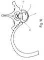
- FIG. 1shows a ventral intervertebral implant, generally designated 1, which has a cross-sectional shape approximating the cross section of a vertebral body, which can be clearly seen from FIG. 10.
- the ventral side 2 of the intervertebral implant 1is convex, whereas the dorsal side 3 is flat. It is also conceivable that this dorsal side 3 is curved concavely.
- Elongated openings 4 and 5can be seen between these two sides 2 and 3, which allow connective tissue and bone tissue to grow into the implant 1.
- two recesses 6 and 7can be seen in which anchor bolts 8 (FIGS. 4 and 5) are mounted.
- recesses 9 and 10are indicated, which open out from the implant 1 on the opposite contact surface 11.
- the exceptions 6 and 7 as well as 9 and 10are on one level.
- the contact surface 12 and the contact surface 11(FIG. 2) have a profiled surface which is sawtooth-shaped.
- the serration 13 of the contact surface 12 for the implant 1has a ventrally inhibiting effect and the serration 14 of the contact surface 11 for the implant 1 has a dorsal inhibiting effect.
- These saw teeth 13 and 14prevent the intervertebral implant 1 from slipping on or between the adjacent vertebral bodies 15 (FIG. 10).
- the intervertebral implant 1In the side view of the intervertebral implant 1, which is shown in FIG. 2, there is another opening 16 recognizable, which allows ingrowth of connective and bone tissue.
- the wedge-shaped configurationcan be seen, the wedge angle ⁇ being between 2 ° and 15 °.
- the thickness of the implant 1 on the ventral side 2is 5 mm and 8 mm on the dorsal side.
- the camshaft 18has three collars 19 to 21, over which it is supported. Between the collars 19 and 20 there are two cams 22 and 23 and between the collars 20 and 21 there are two cams 24 and 25. The collars 19 to 21 protrude radially from the cams 22 to 25 so that between the surfaces of the cams 22 to 25 and the bore wall 17 always have a free space. From FIG. 3, an internal thread 26 provided in the collar 21 is also indicated, into which a tool 30, which has a threaded bolt 32, is screwed and with which the camshaft 18 can be rotated. The tool 30 can have a handle, not shown, for easy gripping. The internal thread 26 is slightly eccentric, in particular coaxial to the cam 25, so that no unnecessary wall weakening occurs.
- the camshaft 18can be removed with the tool 30 and replaced with a device 29 holding the anchor bolts 8 in the working position.
- This device 29 shown in FIG. 3aalso has a thread 26 and is provided with a minimal radial projection 31 (shown exaggerated in the drawing), which ensures that the insert 29 is jammed in the implant 1.
- the camshaft 18 and the tool 30thus form an instrument, which is why the camshaft 18 can be used several times.
- the camshaft 18is shown in section and the anchor bolts 8 are in their rest position, i.e. shown in its retracted position.
- the proximal ends 27rest on the cams 22 to 25 and the distal ends 28 slightly project beyond the contact surfaces 11 and 12, i.e. only to the extent that insertion of the intervertebral implant 1 between two vertebral bodies 15 is possible without problems.
- the anchor bolts 8are shown in the extended position and the camshaft 18 assumes a position rotated by 180 °. It can also be seen that the proximal ends 27 of the anchor bolts 8 are flush with the bore wall 17.
- FIG. 6shows an end view of the camshaft 18 in FIG.
- FIG. 7shows an end view of the camshaft 18 in FIG.
- FIG. 7shows an end view of the camshaft 18 in FIG.
- FIG. 7shows an end view of the camshaft 18 in FIG.
- FIG. 7shows an end view of the camshaft 18 in FIG.
- FIG. 7shows an end view of the camshaft 18 in FIG.
- FIG. 7shows an end view of the camshaft 18 in FIG.
- FIG. 7shows an end view of the camshaft 18 in FIG.
- FIG. 7shows an end view of the camshaft 18 in FIG.
- FIG. 7shows an end view of the camshaft 18 in FIG.
- FIG. 7shows an end view of the camshaft 18 in FIG.
- FIG. 7shows an end view of the camshaft 18 in FIG.
- FIG. 7shows an end view of the camshaft 18 in FIG.
- FIG. 7shows an end view of the camshaft 18 in FIG.
- the cam travelalso extends over 180 °, but only a single cam is required to extend opposing anchor bolts 8, so that twice the number of anchor bolts 8 can be moved.
- This camhas a given direction of rotation.
- the camshafttherefore also has a rotary stop, which is not shown in the drawing.
- FIG. 9shows a further embodiment of a cam which has an adjustment path extending over 360 °.
- This camalso has a defined direction of rotation and thus the camshaft has a rotary stop.
Landscapes
- Health & Medical Sciences (AREA)
- Engineering & Computer Science (AREA)
- Biomedical Technology (AREA)
- Orthopedic Medicine & Surgery (AREA)
- Neurology (AREA)
- Transplantation (AREA)
- Oral & Maxillofacial Surgery (AREA)
- Cardiology (AREA)
- Heart & Thoracic Surgery (AREA)
- Vascular Medicine (AREA)
- Life Sciences & Earth Sciences (AREA)
- Animal Behavior & Ethology (AREA)
- General Health & Medical Sciences (AREA)
- Public Health (AREA)
- Veterinary Medicine (AREA)
- Physical Education & Sports Medicine (AREA)
- Prostheses (AREA)
Abstract
Description
Translated fromGermanDie Erfindung betrifft ein ventrales Zwischenwirbelimplantat zum Einsatz beispielsweise zwischen zwei Wirbelkörper einer Wirbelsäule mit einer oberen und einer unteren Anlagefläche und mindestens einem wenigstens eine Anlagefläche überragenden Ankerbolzen, wobei der mindestens eine Ankerbolzen versenkbar angeordnet ist und das Implantat zum Ausfahren des Ankerbolzens ein Getriebe aufweist.The invention relates to a ventral intervertebral implant for use, for example, between two vertebral bodies of a spine with an upper and a lower contact surface and at least one anchor bolt projecting above at least one contact surface, the at least one anchor bolt being arranged so as to be retractable and the implant having a gear for extending the anchor bolt.
Die einzelnen Wirbel der Wirbelsäule weisen unter anderem einen Wirbelkörper, einen Wirbelbogen, einen Dornfortsatz, zwei Querfortsätze und zwei obere und zwei untere Gelenkfortsätze auf. Die Wirbel sind über an ihren Wirbelkörpern (Corpus vertebrae) anliegenden Zwischenwirbelscheiben (Disci intervertebralis) miteinander verbunden. Diese Zwischenwirbelscheiben bestehen aus flüssigkeitsreichem Faserknorpel und verbinden die einzelnen Wirbelkörper miteinander. Die Größe der Zwischenwirbelscheiben nimmt von oben nach unten entsprechend der im menschlichen Körper auftretenden Belastung zu. Die Zwischenwirbelscheiben dienen als elastische Puffer und dämpfen federnd Stöße ab. Es ist bekannt, daß sich die Zwischenwirbelscheiben verlagern können oder daß der innere Gallertkern (Nucleus pulposus) durch Risse im bindegewebartigen knorpeligen äußeren Ring (Annulus fibrosus) austreten kann. Dabei kann die Zwischenwirbelscheibe teilweise in die Zwischenwirbellöcher (Foramina intervertebralia) bzw. in den Spinalkanal eintreten. Außerdem kann dieser Prolaps medial bzw. dorsalmedial oder lateral sein. Derartige Prolapse treten am häufigsten an den L₄-L₅, L₅-S₁ und C₆-C₇-Vertebrales auf. Werden derartige Prolapse nicht therapiert kommt es zu irreversiblen Druckschädigungen von Nervenwurzeln oder zu Querschnittsläsionen. Sollte eine symtomatische Physiotherapie, z.B. Krankengymnastik oder Massage, keinen Erfolg versprechen, muß die Discus intervertebralis operativ entfernt werden. Nun besteht die Möglichkeit der Implantation einer künstlichen Zwischenwirbelscheibe oder der Osteosynthese der beiden Wirbel über ein starres Zwischenwirbelimplantat.The individual vertebrae of the spine include a vertebral body, a vertebral arch, a spinous process, two transverse processes and two upper and two lower articular processes. The vertebrae are connected to each other via intervertebral discs (disci intervertebralis) which are in contact with their vertebral bodies (corpus vertebrae) connected. These intervertebral discs consist of fluid-rich fibrous cartilage and connect the individual vertebrae with each other. The size of the intervertebral discs increases from top to bottom according to the stress occurring in the human body. The intervertebral discs serve as elastic buffers and dampen bumps. It is known that the intervertebral discs can shift or that the inner gelatin nucleus (nucleus pulposus) can emerge through tears in the connective tissue-like cartilaginous outer ring (annulus fibrosus). The intervertebral disc can partially enter the intervertebral holes (foramina intervertebralia) or the spinal canal. This prolapse can also be medial, dorsal medial or lateral. Such prolapses occur most frequently on the L₄-L₅, L₅-S₁ and C₆-C₇ vertebrales. If such prolapses are not treated, irreversible pressure damage to nerve roots or cross-sectional lesions will result. If symptomatic physiotherapy, such as physiotherapy or massage, does not promise success, the intervertebral disc must be surgically removed. Now there is the possibility of implanting an artificial intervertebral disc or osteosynthesis of the two vertebrae using a rigid intervertebral implant.
Aus der EP 392 076 A1 ist eine künstliche Zwischenwirbelscheibe bekannt geworden, die aus einer oberen und unteren Anlagefläche und einer elastischen Zwischenschicht besteht. Aus der Anlagefläche ragen Ankerbolzen heraus, über die die künstliche Zwischenwirbelscheibe an den Wirbelkörpern fixiert wird. Als nachteilig hat sich herausgestellt, daß diese bekannte künstliche Zwischenwirbelscheibe nur mit Mühe zwischen die beiden Wirbelkörper einsetzbar ist, da die Ankerbolzen das Einsetzen behindern.From EP 392 076 A1 an artificial intervertebral disc is known, which consists of an upper and lower contact surface and an elastic intermediate layer. Anchor bolts protrude from the contact surface and fix the artificial intervertebral disc to the vertebral bodies. It has been found to be disadvantageous that this known artificial intervertebral disc is difficult to insert between the two vertebral bodies, since the anchor bolts hinder the insertion.
Aus der US 5,192,327 ist ein starres Zwischenwirbelimplantat bekannt geworden, welches zur Osteosynthese ebenfalls zwischen zwei Wirbelkörper eingesetzt wird. Die beiden Anlageflächen dieses Implantats sind mit mit V-förmigen Längsnuten versehen, wodurch die Fixierung dieses Implantats an den Wirbelkörpern erzielt werden soll. Es hat sich gezeigt, daß insbesondere in den ersten zwölf bis sechszehn Wochen nach der Implantation das Implantat besonders leicht verrutscht, da zu diesem Zeitpunkt die Fixierung über die V-förmigen Nuten nicht ausreichend ist. Erst allmählich wächst Bindegewebe in die Durchbrüche des Implantats ein und fixiert so das Implantat am Wirbelkörper.From US 5,192,327 a rigid intervertebral implant has become known, which is also used for osteosynthesis between two vertebral bodies. The two contact surfaces of this implant are provided with V-shaped longitudinal grooves, whereby the fixation of this implant to the vertebral bodies is to be achieved. It has been shown that the implant slips particularly easily in the first twelve to sixteen weeks after the implantation, since at this point the fixation via the V-shaped grooves is not sufficient. Connective tissue only gradually grows into the breakthroughs of the implant and thus fixes the implant to the vertebral body.
Mit der WO 90/00037 ist eine künstliche Zwischenwirbelscheibe bekannt geworden, die, gemäß dem Oberbegriff des Anspruchs 1, die Anlagefläche überragende Ankerbolzen aufweist. Bei dieser Zwischenwirbelscheibe müssen aber die einzelnen Ankerbolzen schwenkbar gelagert sein, wobei der Schwenkarm eine gewisse Länge aufweisen muß. Im Bereich dieses Schwenkarmes können keine Ankerbolzen vorgesehen werden. Die Anzahl der Ankerbolzen ist daher auf eine gerine Zahl beschränkt. Außerdem beschreiben die Ankerbolzen beim Ausfahren einen Kreisbogen, was unter Umständen unerwünscht ist. Eine optimale Fixierung ist daher nicht immer gewährleistet.With WO 90/00037 an artificial intervertebral disc has become known which, according to the preamble of claim 1, has anchor bolts which project beyond the contact surface. In this intervertebral disc, however, the individual anchor bolts must be pivotally mounted, the pivot arm having to have a certain length. In the area of this swivel arm no anchor bolts are provided. The number of anchor bolts is therefore limited to a small number. In addition, the anchor bolts describe an arc when extending, which may be undesirable. An optimal fixation is therefore not always guaranteed.
Der Erfindung liegt daher die Aufgabe zugrunde, ein Zwischenwirbelimplantat mit dem eingangs genannten Aufbau bereitzustellen, welches einerseits einfach z.B. ventral oder dorsal zwischen die Wirbelkörper einzuführen und optimal an diesen fixierbar ist und außerdem zur Kostendämpfung beiträgt.The invention is therefore based on the object of providing an intervertebral implant with the structure mentioned at the outset, which on the one hand simply e.g. to be inserted ventrally or dorsally between the vertebral bodies and can be optimally fixed to them and also helps to reduce costs.
Diese Aufgabe wird dadurch gelöst, daß das Getriebe ein Instrument oder Teil eines Instruments ist.This object is achieved in that the transmission is an instrument or part of an instrument.
Durch die versenkbare Anordnung des bzw. der Ankerbolzen kann somit das Implantat bei versenktem bzw. versenkten Ankerbolzen problemlos zwischen die beiden Wirbelkörper eingeschoben werden, d.h. der Abstand zwischen den beiden Wirbelkörpern muß nicht größer sein als die Höhe des Implantats. Neben der einfacheren Plazierung müssen die beiden Wirbelkörper nach dem Entfernen der Zwischenwirbelscheibe zum Einführen des Implantats nicht noch weiter auseinandergedrängt werden, was unter Umständen Verletzungen an den Gelenkflächen zur Folge haben könnte. Der Abstand der Wirbelkörper vor und nach der Operation ist in der Regel gleich bzw. entspricht dem Abstand als ob eine gesunde Zwischenwirbelscheibe vorhanden wäre.Due to the retractable arrangement of the anchor bolt or bolts, the implant can be easily inserted between the two vertebral bodies when the anchor bolt is countersunk or retracted, ie the distance between the two vertebral bodies need not be greater than the height of the implant. In addition to the simpler placement, the two vertebral bodies do not have to be pushed apart further after the removal of the intervertebral disc for insertion of the implant, which under certain circumstances could result in injuries to the articular surfaces. The distance between the vertebral bodies before and after the operation is usually the same or corresponds to the distance as if there was a healthy intervertebral disc.
Um nach dem Plazieren des Implantats dieses mit den Wirbelkörpern zu fixieren, werden die Ankerbolzen über das Getriebe aus der versenkten Lage ausgeschoben und dringen in die Wirbelkörper ein. Hierdurch wird eine optimale Primärfixierung des Implantats erreicht, so daß die Ruhigstellung des Patienten bereits kurze Zeit nach der Operation aufgehoben werden kann. Die Primärfixierung durch die ausgefahrenen Ankerbolzen hat außerdem den Vorteil, daß das Implantat und die anliegenden Wirbelkörper keine Relativbewegungen zueinander ausführen können und dadurch das Bindegewebe sofort nach der Operation in das Implantat eindringen kann. Hierdurch wird der Heilprozeß wesentlich beschleunigt.In order to fix the implant with the vertebral bodies after the implant has been placed, the anchor bolts are pushed out of the lowered position via the gear and penetrate into the vertebral bodies. In this way, an optimal primary fixation of the implant is achieved, so that the immobilization of the patient can be released shortly after the operation. The primary fixation by means of the extended anchor bolts also has the advantage that the implant and the adjacent vertebral bodies cannot move relative to one another and the connective tissue can penetrate the implant immediately after the operation. This significantly speeds up the healing process.
Erfindungsgemäß ist das Getriebe als Instrument ausgebildet und wird nach dem Ausschieben der Ankerbolzen in deren Arbeitslage, in der sie die Oberfläche(n) des Implantats überragen, aus dem Implantat entfernt. Dies hat den entscheidenden Vorteil, daß das Getriebe mehrmals verwendbar ist, was erheblich zur Kostendämpfung beiträgt. Derartige Getriebe sind, wie weiter unten noch ausführlicher erläutert, zum Teil sehr aufwendig in der Herstellung, weshalb eine nur einmalige Nutzung nicht gerechtfertigt ist.According to the invention, the transmission is designed as an instrument and is removed from the implant after the anchor bolts have been pushed out in their working position, in which they protrude above the surface (s) of the implant. This has the decisive advantage that the transmission can be used several times, which contributes significantly to the cost reduction. Such gears, as explained in more detail below, are sometimes very complex to manufacture, which is why just one use is not justified.
Bei einem Ausführungsbeispiel weist das Getriebe eine axiale Gewindebohrung auf, in die ein Gewindezapfen einer manuell betätigbaren Instrumentenstange eindrehbar ist.In one embodiment, the transmission has an axial threaded hole into which a threaded pin of a manually operable instrument rod can be screwed.
Vorteilhaft verrasten die Ankerbolzen in ihrer Arbeitslage nachdem sie über das Getriebe ausgeschoben worden sind. Bei einer Weiterbildung ist vorgesehen, daß diese Verrastung wieder lösbar ist. Außerdem können die Ankerbolzen über das Getriebe wieder eingefahren werden. Das Getriebe ist dorsal oder ventral in das Implantat einsetzbar. Hierfür weist das Implantat entsprechende Öffnungen bzw. eine Durchgangsöffnung auf.The anchor bolts advantageously lock in their working position after they have been pushed out over the gear. In a further development it is provided that this latching can be released again. The anchor bolts can also be retracted using the gearbox. The gearbox can be inserted dorsally or ventrally into the implant. For this purpose, the implant has corresponding openings or a through opening.
Bei einer Ausführungsform weist das Getriebe einen den bzw. die Achsbolzen ausschiebenden Keil auf. Bei einem anderen Ausführungsbeispiel weist das Getriebe eine drehbar gelagerte, den Ankerbolzen ausschiebende Nocke auf. Bei diesem Getriebe werden Bewegungs- und Kraftrichtungen in Richtung des Ankerbolzens umgelenkt. Dabei kann z.B. durch eine Verschiebe- oder Drehbewegung der Ankerbolzen aus seiner versenkten Lage durch entsprechende Ausnehmungen in der Anlagefläche hindurch ausgeschoben und in den Wirbelkörper eingeschoben werden.In one embodiment, the transmission has a wedge that pushes out the axle pin or pins. In another embodiment, the transmission has a rotatably mounted cam that pushes out the anchor bolt. With this gearbox, directions of movement and force are deflected in the direction of the anchor bolt. Here, e.g. can be pushed out of its recessed position through corresponding recesses in the contact surface and pushed into the vertebral body by a displacement or rotary movement of the anchor bolts.
Bevorzugt sind mehrere Ankerbolzen über eine oder mehrere Nocken ausschiebbar. Auf diese Weise können gleichzeitig mehrere Ankerbolzen aus ihrer Ruhelage in die Arbeitslage gebracht werden und in einen oder beide Wirbelkörper eindringen.A plurality of anchor bolts can preferably be pushed out via one or more cams. In this way, several anchor bolts can be brought from their rest position into the working position at the same time and penetrate one or both vertebrae.
Bei einer Weiterbildung ist vorgesehen, daß die eine Nocke oder mehrere Nocken auf einer oder mehreren Wellen angeordnet sind. Insbesondere bei größeren Implantaten, z.B. für die Vertebrae lumbales des Lendenwirbelbereiches empfiehlt es sich, wenigstens in zwei Ebenen Ankerbolzen anzuordnen, die über zwei Wellen betätigt werden. Für die Vertebrae cervicales des Halswirbelbereiches, d.h. für den Bereich der C₁-C₇-Wirbeln genügt eine Welle, über die die Ankerbolzen in einer Ebene ausgeschoben werden.In a further development it is provided that the one cam or several cams is arranged on one or more shafts are. Particularly in the case of larger implants, for example for the lumbar vertebrae of the lumbar region, it is advisable to arrange anchor bolts which are actuated by two shafts at least in two planes. For the vertebrae cervicales of the cervical vertebrae, ie for the area of the C₁-C₇ vertebrae, a wave is sufficient, through which the anchor bolts are pushed out in one plane.
Bevorzugt ist die Welle in einer zwischen den Anlageflächen vorgesehenen Bohrung gelagert. Derartige Lagerungen sind einfach herzustellen und nehmen die gesamte Welle vollständig auf. Dabei kann die Bohrung derart angeordnet sein, daß die Welle ventral oder dorsal oder lateral zugänglich ist.The shaft is preferably mounted in a bore provided between the contact surfaces. Such bearings are easy to manufacture and take up the entire shaft. The bore can be arranged such that the shaft is accessible ventrally or dorsally or laterally.
Eine einfache Handhabung der Welle wird dadurch erzielt, daß sie über ein Werkzeug bewegbar ist und ein Innengewinde oder eine entsprechende Werkzeugangriffseinrichtung aufweist. Ein Innengewinde wird bevorzugt, da mit diesem die Nockenwelle auf einfache Weise mit dem Werkzeug verbindbar ist, bzw. verschiedene Wellen mit dem Werkzeug verbindbar sind.Simple handling of the shaft is achieved in that it can be moved via a tool and has an internal thread or a corresponding tool engagement device. An internal thread is preferred since the camshaft can be connected to the tool in a simple manner, or different shafts can be connected to the tool.
Bei einer bevorzugten Ausführungsform ist die Welle nach Art einer Nockenwelle mit mehreren axial hintereinander angeordneten Nocken ausgebildet. Wird eine derartige Welle um ihre Achse gedreht, dann werden die Ankerbolzen über die Nocken gleichzeitig oder nacheinander ausgeschoben. Ein gleichzeitiges Ausschieben hat den Vorteil, daß die Nocken mit einem sehr langen Stellweg versehen werden können, wohingegen ein sequenzieller Ausschub den Vorteil hat, daß gezielt nur die erforderliche Anzahl von Ankerbolzen ausgeschoben werden kann.In a preferred embodiment, the shaft is designed in the manner of a camshaft with a plurality of cams arranged axially one behind the other. If such a shaft is rotated about its axis, the anchor bolts are pushed out simultaneously or in succession via the cams. A simultaneous pushing out has the advantage that the cams with a very long travel can be provided, whereas a sequential extension has the advantage that only the required number of anchor bolts can be extended.
Bevorzugt ist zwischen den Nocken oder zwischen mehreren Nocken jeweils ein die Nocken radial überragender, scheibenförmiger Bund vorgesehen. Da die Achsbolzen mit ihrer proximalen Stirnseite auf der Nocke aufliegen, wird ein Auszug der Welle aus der Bohrung über die radial überstehenden Bünde verhindert, da diese seitlich an den Ankerbolzen anliegen.Between the cams or between a plurality of cams, a disk-shaped collar projecting radially above the cams is preferably provided. Since the axle bolts rest with their proximal end faces on the cam, the shaft is prevented from being pulled out of the bore via the radially projecting collars, since these lie laterally on the anchor bolts.
Dabei bildet vorteilhaft ein jeder Bund eine Lagerstelle für die Welle. Entsprechend kann die Oberfläche eines jeden Bundes so aufbereitet sein, daß entweder eine geringe Reibung für eine leichte Verstellung bzw. Verdrehung der Welle oder eine hohe Reibung als Sicherheit gegen ein selbsttätiges Verdrehen der Welle erzielt wird.Each collar advantageously forms a bearing for the shaft. Accordingly, the surface of each collar can be prepared in such a way that either low friction for easy adjustment or twisting of the shaft or high friction as security against automatic rotation of the shaft is achieved.
Bei einem Ausführungsbeispiel erstreckt sich der Stellweg der Nocke über 180° oder 360°. Bei einem Stellweg von 360° verteilt sich die gesamte Stellkraft auf eine volle Umdrehung der Welle. Bei einem Stellweg von 180° können auf gegenüberliegenden Seiten Ankerbolzen vorgesehen sein, die dann gleichzeitig durch eine halbe Umdrehung der Welle ausgefahren werden können. Dabei kann ein Nocken mit zwei sich über jeweils 180° erstreckende Stellwege versehen sein.In one embodiment, the cam travel path extends over 180 ° or 360 °. With a travel of 360 °, the entire positioning force is distributed over a full rotation of the shaft. With an adjustment path of 180 °, anchor bolts can be provided on opposite sides, which can then be extended simultaneously by half a turn of the shaft. A cam can be provided with two adjustment paths each extending over 180 °.
Falls die Welle nur eine Drehrichtung aufweist, kann die Welle mit einem Drehanschlag versehen sein. Durch diesen Anschlag werden Fehlbedienungen vermieden, insbesondere ein Überdrehen der Welle verhindert.If the shaft has only one direction of rotation, the shaft can be provided with a rotary stop. This stop prevents incorrect operation, in particular prevents the shaft from overtightening.
Gemäß einem bevorzugten Ausführungsbeispiel weisen die Ankerbolzen einen zylindrischen Querschnitt auf und sind in entsprechenden Ausnehmungen im Implantat gelagert. Die Ankerbolzen können z.B. als kreiszylindrische Stifte mit distaler Spitze ausgebildet sein, die mit ihrem proximalen flachen Ende auf der Nocke aufliegen.According to a preferred embodiment, the anchor bolts have a cylindrical cross section and are mounted in corresponding recesses in the implant. The anchor bolts can e.g. be designed as circular cylindrical pins with a distal tip, which rest on the cam with their proximal flat end.
Eine optimale Anpassung des Implantats an dei Form von Zwischenwirbelscheiben wird dann dadurch erzielt, daß das Implantat keilförmig ausgebildet ist und die beiden Anlageflächen einen Keilwinkel von 2° bis 15°, insbesondere von 3° bis 10° einschließen. Vor allem im Bereich der C₁-C₇-Wirbel, die eine Lordosestellung einnehmen, wird die Lage der miteinander zu verbindenden Wirbel über das Implantat beibehalten. Entsprechendes gilt für die Vertebrae lumbales, wo die Wirbel ebenfalls eine Lordosestellung einnehmen. Bei der Vertrebae thoracales nehmen die einzelnen Wirbel eine Kyphosestellung ein, so daß hier Implantate mit einem um 180° gedrehten Keilwinkel eingesetzt werden können.An optimal adaptation of the implant to the shape of intervertebral discs is then achieved in that the implant is wedge-shaped and the two contact surfaces enclose a wedge angle of 2 ° to 15 °, in particular 3 ° to 10 °. Especially in the area of the C₁-C verbind vertebrae, which assume a lordosis position, the position of the vertebrae to be connected to one another is maintained via the implant. The same applies to the vertebrae lumbar, where the vertebrae also assume a lordosis position. With the Vertrebae thoracales, the individual vertebrae assume a kyphosis position, so that implants with a wedge angle rotated by 180 ° can be used here.
Auch die Dicke des Implantats entspricht dem jeweiligen Einsatzort, d.h. bei der Vertebrae cervicales werden dünnere Implantate eingesetzt als bei der Vertebrae lumbales. Zusätzlich zur Primärfixation weist das Implantat zur Langzeitfixation wenigstens eine Anlagefläche mit einer profilierten Oberfläche auf, die insbesondere mit einer Sägeverzahnung versehen ist. Durch die Sägeverzahnung kann das Implantat gezielt gegen einseitig wirkende Verschiebekräfte gesichert werden. Vorteilhaft weisen beide Anlageflächen Sägeverzahnungen auf, die in verschiedene Richtungen, z.B. die eine ventral und die andere dorsal hemmen. Derart ausgebildete Implantate sind besonders unanfällig gegen Verschiebekräfte z.B. gegen ein weiteres Einschieben in dorsaler Richtung bzw. gegen ein Ausschieben in ventraler Richtung.The thickness of the implant also corresponds to the respective place of use, ie the vertebrae cervicales become thinner Implants used as in the vertebrae lumbar. In addition to the primary fixation, the implant for long-term fixation has at least one contact surface with a profiled surface, which is in particular provided with a saw toothing. The saw toothing can be used to specifically secure the implant against unilateral displacement forces. Advantageously, both contact surfaces have serrations that inhibit in different directions, for example one ventrally and the other dorsally. Implants designed in this way are particularly insensitive to displacement forces, for example against further insertion in the dorsal direction or against extension in the ventral direction.
Weitere Vorteile, Merkmale und Einzelheiten ergeben sich aus der nachfolgenden Beschreibung, in der unter Bezugnahme auf die Zeichnung besonders bevorzugte Ausführungsbeispiele im einzelnen dargestellt sind. Dabei können die in den Ansprüchen und der Beschreibung erwähnten und in der Zeichnung dargestellten Merkmale jeweils einzeln für sich oder in beliebiger Kombination erfindungswesentlich sein. In der Zeichnung zeigen:
- Figur 1
- eine Draufsicht auf ein ventrales Zwischenwirbelimplantat;
Figur 2- eine Seitenansicht des Zwischenwirbelimplantats der Figur 1;
Figur 3- einen Schnitt III-
III gemäß Figur 2; - Figur 3a
- einen Schnitt durch eine Halteeinrichtung für die Ankerbolzen;
Figur 4- einen Schnitt IV-
IV gemäß Figur 3 mit versenkt angeordneten Ankerbolzen; Figur 5- einen Schnitt IV-
IV gemäß Figur 3 mit ausgefahrenen Ankerbolzen; Figur 6- eine Stirnansicht der Nockenwelle der Figur 4;
Figur 7- einen Schnitt VII-
VII gemäß Figur 5 durch die Nockenwelle; Figur 8- einen Querschnitt durch eine weitere Ausführungsform einer Nockenwelle;
- Figur 9
- einen Querschnitt durch eine dritte Ausführungsform einer Nockenwelle; und
- Figur 10
- eine schematische Darstellung eines Vertebrae thoracicae mit aufliegendem Zwischenwirbelimplantat.
- Figure 1
- a plan view of a ventral intervertebral implant;
- Figure 2
- a side view of the intervertebral implant of Figure 1;
- Figure 3
- a section III-III of Figure 2;
- Figure 3a
- a section through a holding device for the anchor bolt;
- Figure 4
- a section IV-IV of Figure 3 with sunk anchor bolts;
- Figure 5
- a section IV-IV of Figure 3 with extended anchor bolts;
- Figure 6
- an end view of the camshaft of Figure 4;
- Figure 7
- a section VII-VII of Figure 5 through the camshaft;
- Figure 8
- a cross section through a further embodiment of a camshaft;
- Figure 9
- a cross section through a third embodiment of a camshaft; and
- Figure 10
- a schematic representation of a vertebrae thoracicae with overlying intervertebral implant.
Die Figur 1 zeigt ein insgesamt mit 1 bezeichnetes ventrales Zwischenwirbelimplantat, welches eine dem Querschnitt eines Wirbelkörper angenäherte Querschnittsform aufweist, was deutlich aus Figur 10 erkennbar ist. Entsprechend ist die ventrale Seite 2 des Zwischenwirbelimplantats 1 konvex ausgebildet, wohingegen die dorsale Seite 3 eben gestaltet ist. Es ist auch denkbar, daß diese dorsale Seite 3 konkav gekrümmt ist. Zwischen diesen beiden Seiten 2 und 3 sind längliche Durchbrüche 4 und 5 erkennbar, die ein Einwachsen von Binde- und Knochengewebe in das Implantat 1 ermöglichen. Ferner sind zwei Ausnehmungen 6 und 7 erkennbar, in denen Ankerbolzen 8 (Figuren 4 und 5) gelagert sind. Schließlich sind Ausnehmungen 9 und 10 angedeutet, die auf der gegenüberliegenden Anlagefläche 11 aus dem Implantat 1 ausmünden. Die Ausnhemungen 6 und 7 sowie 9 und 10 befinden sich in einer Ebene. Ferner ist erkennbar, daß die Anlagefläche 12 sowie die Anlagefläche 11 (Figur 2) eine profilierte Oberfläche aufweist, die sägezahnartig ausgebildet ist. Dabei wirkt die Sägezahnung 13 der Anlagefläche 12 für das Implantat 1 nach ventral hemmend und die Sägezahnung 14 der Anlagefläche 11 für das Implantat 1 nach dorsal hemmend. Diese Sägezahnungen 13 und 14 verhindern ein Verrutschen des Zwischenwirbelimplantats 1 auf bzw. zwischen den anliegenden Wirbelkörpern 15 (Figur 10).FIG. 1 shows a ventral intervertebral implant, generally designated 1, which has a cross-sectional shape approximating the cross section of a vertebral body, which can be clearly seen from FIG. 10. Correspondingly, the
In der Seitenansicht des Zwischenwirbelimplantats 1, die in der Figur 2 dargestellt ist, ist ein weiterer Durchbruch 16 erkennbar, der ein Einwachsen von Binde- und Knochengewebe erlaubt. Außerdem ist die keilförmige Ausgestaltung erkennbar, wobei der Keilwinkel α zwischen 2° und 15° liegt. Die Dicke des Implantats 1 auf der ventralen Seite 2 beträgt 5 mm und auf der dorsalen Seite 8 mm.In the side view of the intervertebral implant 1, which is shown in FIG. 2, there is another
Aus dem in Figur 3 dargestellten Schnitt III-III ist erkennbar, daß zwischen den beiden Durchbrüchen 4 und 5 eine Bohrung 17 liegt, die als Lager für eine insgesamt mit 18 bezeichnete Nockenwelle dient. Diese Nockenwelle 18 bildet das Getriebe für die Ankerbolzen 8, insbesondere für deren Verschiebung von der in der Figur 4 dargestellten Ruhelage in die in der Figur 5 dargestellte Arbeitslage.From section III-III shown in Figure 3 it can be seen that between the two
Die Nockenwelle 18 weist drei Bünde 19 bis 21 auf, über die sie gelagert ist. Zwischen den Bünden 19 und 20 befinden sich zwei Nocken 22 und 23 und zwischen den Bünden 20 und 21 befinden sich zwei Nocken 24 und 25. Die Bünde 19 bis 21 überragen die Nocken 22 bis 25 radial, so daß zwischen den Oberflächen der Nocken 22 bis 25 und der Bohrungswand 17 stets ein Freiraum verbleibt. Aus Figur 3 ist ferner ein im Bund 21 vorgesehenes Innengewinde 26 angedeutet, in das ein Werkzeug 30, welches einen Gewindebolzen 32 aufweist, eingeschraubt und mit diesem die Nockenwelle 18 gedreht werden kann. Das Werkzeug 30 kann eine nicht gezeigte Handhabe zum einfachen Ergreifen aufweisen. Das Innengewinde 26 liegt geringfügig exzentrisch, insbesondere koaxial zur Nocke 25, so daß keine unnötigen Wandschwächungen eintreten.The
Nach der Fixierung des Implantats 1 kann die Nockenwelle 18 mit dem Werkzeug 30 entfernt und gegen eine die Ankerbolzen 8 in der Arbeitslage haltende Einrichtung 29 ersetzt werden. Diese in der Figur 3a dargestellte Einrichtung 29 weist ebenfalls ein Gewinde 26 auf und ist mit einem minimalen radialen Vorsprung 31 versehen (in der Zeichnung übertrieben dargestellt), der eine Verklemmung des Einsatzes 29 im Implantat 1 gewährleistet. Die Nockenwelle 18 und das Werkzeug 30 bilden also ein Instrument, weshalb die Nockenwelle 18 mehrfach verwendbar ist.After fixation of the implant 1, the
In Figur 4 ist die Nockenwelle 18 geschnitten dargestellt und es sind die Ankerbolzen 8 in ihrer Ruhelage, d.h. in ihrer eingefahrenen Stellung gezeigt. Dabei liegen die proximalen Enden 27 auf den Nocken 22 bis 25 auf und die distalen Enden 28 überragen die Anlageflächen 11 und 12 geringfügig, d.h. nur soweit, daß ein Einschieben des Zwischenwirbelimplantats 1 zwischen zwei Wirbelkörper 15 problemlos möglich ist.In Figure 4, the
In Figur 5 sind die Ankerbolzen 8 in ausgefahrener Stellung dargestellt und die Nockenwelle 18 nimmt eine um 180° gedrehte Lage ein. Ferner ist erkennbar, daß die proximalen Enden 27 der Ankerbolzen 8 bündig zur Bohrungswand 17 liegen.In Figure 5, the
Die radial versetzte Lage des Innengewindes 26 ist auch deutlich aus Figur 6 erkennbar, die eine Stirnansicht der Nockenwelle 18 der Figur 4 zeigt. Ein Schnitt VII-VII gemäß Figur 5 durch die Nockenwelle 18 ist in Figur 7 dargestellt, wo die beiden Nocken 24 und 25 erkennbar sind. Bei dieser Ausführungsform der Nockenwelle wird der Hub der Nocke durch eine Drehung um 180° erreicht, so daß sich der Stellweg über 180° erstreckt. Ebenfalls aus Figur 7 ist erkennbar, daß die beiden Nocken 24 und 25 einen Winkelversatz von 180° aufweisen, so daß einander gegenüberliegende und die beiden Anlageflächen 11 und 12 durchgreifende Ankerbolzen 8 gleichzeitig ausgeschoben werden.
Bei dem in der Figur 8 dargestellten Ausführungsbeispiel einer Nockenwelle 18 erstreckt sich der Stellweg der Nocke ebenfalls über 180°, wobei aber zum Ausfahren von einander gegenüberliegenden Ankerbolzen 8 lediglich eine einzige Nocke erforderlich ist, so daß die doppelte Anzahl von Ankerbolzen 8 bewegt werden kann. Diese Nocke hat eine vorgegebene Drehrichtung. Die Nockenwelle weist deshalb auch einen Drehanschlag, der in der Zeichnung nicht dargestellte ist, auf.The radially offset position of the
In the embodiment of a
In der Figur 9 ist eine weitere Ausführungsform einer Nocke dargestellt, die einen sich über 360° erstreckenden Stellweg besitzt. Mit derart gestalteten Nocken können lange Verschiebewege bei geringen Verschiebekräften erzielt werden.FIG. 9 shows a further embodiment of a cam which has an adjustment path extending over 360 °. With cams designed in this way, long displacement paths can be achieved with low displacement forces.
Auch diese Nocke weist eine definierte Drehrichtung und somit die Nockenwelle einen Drehanschlag auf.This cam also has a defined direction of rotation and thus the camshaft has a rotary stop.
Claims (15)
Translated fromGermanApplications Claiming Priority (2)
| Application Number | Priority Date | Filing Date | Title |
|---|---|---|---|
| DE9413471UDE9413471U1 (en) | 1994-08-20 | 1994-08-20 | Ventral intervertebral implant |
| DE9413471U | 1994-08-20 |
Publications (2)
| Publication Number | Publication Date |
|---|---|
| EP0697200A1true EP0697200A1 (en) | 1996-02-21 |
| EP0697200B1 EP0697200B1 (en) | 2000-01-05 |
Family
ID=6912652
Family Applications (1)
| Application Number | Title | Priority Date | Filing Date |
|---|---|---|---|
| EP95102545AExpired - LifetimeEP0697200B1 (en) | 1994-08-20 | 1995-02-23 | Ventral intervertebral implant |
Country Status (4)
| Country | Link |
|---|---|
| US (1) | US5800547A (en) |
| EP (1) | EP0697200B1 (en) |
| AT (1) | ATE188369T1 (en) |
| DE (2) | DE9413471U1 (en) |
Cited By (30)
| Publication number | Priority date | Publication date | Assignee | Title |
|---|---|---|---|---|
| FR2779941A1 (en)* | 1998-06-23 | 1999-12-24 | Dimso Sa | Intersomatic spinal implant with anchoring elements |
| WO1999066867A1 (en)* | 1998-06-23 | 1999-12-29 | Dimso (Distribution Medicale Du Sud-Ouest) | Backbone intersomatic implant with anchoring elements |
| FR2782914A1 (en)* | 1998-09-04 | 2000-03-10 | Dimso Sa | INTERSOMATIC CAGE TYPE IMPLANT, ESPECIALLY FOR CERVICAL VERTEBRES |
| EP0951879A3 (en)* | 1998-04-23 | 2000-08-02 | Medinorm Aktiengesellschaft Medizintechnische Produkte | Device for connecting vertebrae of the spinal column |
| WO2000044317A1 (en)* | 1998-01-23 | 2000-08-03 | Aesculap Ag & Co. Kg | Intervertebral implant |
| WO2002013732A3 (en)* | 2000-08-11 | 2002-05-30 | Dale G Bramlet | Apparatus and method for fusing opposing spinal vertebrae |
| US6749612B1 (en) | 1998-10-09 | 2004-06-15 | Stryker Spine | Spinal osteosynthesis system with improved rigidity |
| WO2012051132A1 (en)* | 2010-10-13 | 2012-04-19 | Synthes Usa, Llc | Intervertebral implant fixation assembly |
| EP2381899A4 (en)* | 2009-01-20 | 2013-01-16 | Incite Innovation Llc | Interbody fusion device and method of operation |
| US8460388B2 (en) | 2011-10-28 | 2013-06-11 | Incite Innovation Llc | Spinal interbody device |
| US9675389B2 (en) | 2009-12-07 | 2017-06-13 | Samy Abdou | Devices and methods for minimally invasive spinal stabilization and instrumentation |
| US9693876B1 (en) | 2012-03-30 | 2017-07-04 | Ali H. MESIWALA | Spinal fusion implant and related methods |
| US9713535B2 (en) | 2006-02-15 | 2017-07-25 | Ldr Medical | Transforaminal intersomatic cage for an intervertebral fusion graft and an instrument for implanting the cage |
| US9833331B2 (en) | 2009-12-31 | 2017-12-05 | Ldr Medical | Anchoring device and system for an intervertebral implant, intervertebral implant and implantation instrument |
| US10045860B2 (en) | 2008-12-19 | 2018-08-14 | Amicus Design Group, Llc | Interbody vertebral prosthetic device with self-deploying screws |
| US10188528B2 (en) | 2007-02-16 | 2019-01-29 | Ldr Medical | Interveterbral disc prosthesis insertion assemblies |
| US10226355B2 (en) | 2004-12-22 | 2019-03-12 | Ldr Medical | Intervertebral disc prosthesis |
| US10245156B2 (en) | 2012-02-24 | 2019-04-02 | Ldr Medical | Anchoring device and system for an intervertebral implant, intervertebral implant and implantation instrument |
| US10492919B2 (en) | 2005-09-23 | 2019-12-03 | Ldr Medical | Intervertebral disc prosthesis |
| US10548740B1 (en) | 2016-10-25 | 2020-02-04 | Samy Abdou | Devices and methods for vertebral bone realignment |
| US10575961B1 (en) | 2011-09-23 | 2020-03-03 | Samy Abdou | Spinal fixation devices and methods of use |
| US10603185B2 (en) | 2004-02-04 | 2020-03-31 | Ldr Medical | Intervertebral disc prosthesis |
| US10695105B2 (en) | 2012-08-28 | 2020-06-30 | Samy Abdou | Spinal fixation devices and methods of use |
| US10751187B2 (en) | 2007-06-08 | 2020-08-25 | Ldr Medical | Intersomatic cage, intervertebral prosthesis, anchoring device and implantation instruments |
| US10857003B1 (en) | 2015-10-14 | 2020-12-08 | Samy Abdou | Devices and methods for vertebral stabilization |
| US10918498B2 (en) | 2004-11-24 | 2021-02-16 | Samy Abdou | Devices and methods for inter-vertebral orthopedic device placement |
| US10973648B1 (en) | 2016-10-25 | 2021-04-13 | Samy Abdou | Devices and methods for vertebral bone realignment |
| US11006982B2 (en) | 2012-02-22 | 2021-05-18 | Samy Abdou | Spinous process fixation devices and methods of use |
| US11173040B2 (en) | 2012-10-22 | 2021-11-16 | Cogent Spine, LLC | Devices and methods for spinal stabilization and instrumentation |
| US11179248B2 (en) | 2018-10-02 | 2021-11-23 | Samy Abdou | Devices and methods for spinal implantation |
Families Citing this family (265)
| Publication number | Priority date | Publication date | Assignee | Title |
|---|---|---|---|---|
| US7534254B1 (en) | 1988-06-13 | 2009-05-19 | Warsaw Orthopedic, Inc. | Threaded frusto-conical interbody spinal fusion implants |
| US7491205B1 (en) | 1988-06-13 | 2009-02-17 | Warsaw Orthopedic, Inc. | Instrumentation for the surgical correction of human thoracic and lumbar spinal disease from the lateral aspect of the spine |
| US5772661A (en) | 1988-06-13 | 1998-06-30 | Michelson; Gary Karlin | Methods and instrumentation for the surgical correction of human thoracic and lumbar spinal disease from the antero-lateral aspect of the spine |
| US6123705A (en) | 1988-06-13 | 2000-09-26 | Sdgi Holdings, Inc. | Interbody spinal fusion implants |
| US5609635A (en)* | 1988-06-28 | 1997-03-11 | Michelson; Gary K. | Lordotic interbody spinal fusion implants |
| US6758849B1 (en) | 1995-02-17 | 2004-07-06 | Sdgi Holdings, Inc. | Interbody spinal fusion implants |
| US7291149B1 (en) | 1995-06-07 | 2007-11-06 | Warsaw Orthopedic, Inc. | Method for inserting interbody spinal fusion implants |
| EP0845965A1 (en)* | 1996-06-18 | 1998-06-10 | Mehran Kasra | Bone prosthesis fixation device and methods of using same |
| US6068630A (en) | 1997-01-02 | 2000-05-30 | St. Francis Medical Technologies, Inc. | Spine distraction implant |
| US7959652B2 (en) | 2005-04-18 | 2011-06-14 | Kyphon Sarl | Interspinous process implant having deployable wings and method of implantation |
| US20080039859A1 (en) | 1997-01-02 | 2008-02-14 | Zucherman James F | Spine distraction implant and method |
| US20080086212A1 (en) | 1997-01-02 | 2008-04-10 | St. Francis Medical Technologies, Inc. | Spine distraction implant |
| US7201751B2 (en) | 1997-01-02 | 2007-04-10 | St. Francis Medical Technologies, Inc. | Supplemental spine fixation device |
| US7306628B2 (en) | 2002-10-29 | 2007-12-11 | St. Francis Medical Technologies | Interspinous process apparatus and method with a selectably expandable spacer |
| US5876457A (en)* | 1997-05-20 | 1999-03-02 | George J. Picha | Spinal implant |
| DE19753685C1 (en)* | 1997-12-03 | 1999-09-16 | Biedermann Motech Gmbh | Intravertebral surgical implant |
| FR2794968B1 (en) | 1999-06-17 | 2002-09-06 | Dimso Sa | INTERSOMATIC RACHIDIAN IMPLANT WITH HIGHLIGHTS |
| US6193757B1 (en) | 1998-10-29 | 2001-02-27 | Sdgi Holdings, Inc. | Expandable intervertebral spacers |
| DE19902481A1 (en)* | 1999-01-22 | 2000-07-27 | Signus Medizintechnik Gmbh | Vertebra replacement for replacing diseased or damaged vertebra in surgical procedures, has anchoring side and gripping screw |
| US6929662B1 (en) | 1999-02-04 | 2005-08-16 | Synthes (Usa) | End member for a bone fusion implant |
| US6241770B1 (en) | 1999-03-05 | 2001-06-05 | Gary K. Michelson | Interbody spinal fusion implant having an anatomically conformed trailing end |
| US6056749A (en)* | 1999-03-15 | 2000-05-02 | Spineology, Inc. | Method and device for fixing and correcting spondylolisthesis anteriorly |
| AU4988700A (en) | 1999-05-05 | 2000-11-17 | Gary K. Michelson | Spinal fusion implants with opposed locking screws |
| EP1198208B1 (en)* | 1999-05-05 | 2013-07-10 | Warsaw Orthopedic, Inc. | Nested interbody spinal fusion implants |
| AU770261B2 (en)* | 1999-06-04 | 2004-02-19 | Warsaw Orthopedic, Inc. | Artificial disc implant |
| US6770096B2 (en)* | 1999-07-01 | 2004-08-03 | Spinevision S.A. | Interbody spinal stabilization cage and spinal stabilization method |
| US6936071B1 (en) | 1999-07-02 | 2005-08-30 | Spine Solutions, Inc. | Intervertebral implant |
| FR2799639B1 (en)* | 1999-10-18 | 2002-07-19 | Dimso Sa | TOOTHED FACED INTERVERTEBRAL DISC PROSTHESIS |
| US20010032017A1 (en) | 1999-12-30 | 2001-10-18 | Alfaro Arthur A. | Intervertebral implants |
| AR027685A1 (en) | 2000-03-22 | 2003-04-09 | Synthes Ag | METHOD AND METHOD FOR CARRYING OUT |
| US7462195B1 (en) | 2000-04-19 | 2008-12-09 | Warsaw Orthopedic, Inc. | Artificial lumbar interbody spinal implant having an asymmetrical leading end |
| US6350283B1 (en) | 2000-04-19 | 2002-02-26 | Gary K. Michelson | Bone hemi-lumbar interbody spinal implant having an asymmetrical leading end and method of installation thereof |
| US6638310B2 (en) | 2000-07-26 | 2003-10-28 | Osteotech, Inc. | Intervertebral spacer and implant insertion instrumentation |
| US7837716B2 (en)* | 2000-08-23 | 2010-11-23 | Jackson Roger P | Threadform for medical implant closure |
| US7833250B2 (en) | 2004-11-10 | 2010-11-16 | Jackson Roger P | Polyaxial bone screw with helically wound capture connection |
| US20030120274A1 (en) | 2000-10-20 | 2003-06-26 | Morris John W. | Implant retaining device |
| US6726689B2 (en) | 2002-09-06 | 2004-04-27 | Roger P. Jackson | Helical interlocking mating guide and advancement structure |
| US8377100B2 (en) | 2000-12-08 | 2013-02-19 | Roger P. Jackson | Closure for open-headed medical implant |
| US6890355B2 (en)* | 2001-04-02 | 2005-05-10 | Gary K. Michelson | Artificial contoured spinal fusion implants made of a material other than bone |
| US6989031B2 (en) | 2001-04-02 | 2006-01-24 | Sdgi Holdings, Inc. | Hemi-interbody spinal implant manufactured from a major long bone ring or a bone composite |
| US6749636B2 (en) | 2001-04-02 | 2004-06-15 | Gary K. Michelson | Contoured spinal fusion implants made of bone or a bone composite material |
| FR2824261B1 (en) | 2001-05-04 | 2004-05-28 | Ldr Medical | INTERVERTEBRAL DISC PROSTHESIS AND IMPLEMENTATION METHOD AND TOOLS |
| US7862587B2 (en) | 2004-02-27 | 2011-01-04 | Jackson Roger P | Dynamic stabilization assemblies, tool set and method |
| US10729469B2 (en) | 2006-01-09 | 2020-08-04 | Roger P. Jackson | Flexible spinal stabilization assembly with spacer having off-axis core member |
| US8353932B2 (en) | 2005-09-30 | 2013-01-15 | Jackson Roger P | Polyaxial bone anchor assembly with one-piece closure, pressure insert and plastic elongate member |
| US8292926B2 (en) | 2005-09-30 | 2012-10-23 | Jackson Roger P | Dynamic stabilization connecting member with elastic core and outer sleeve |
| US10258382B2 (en) | 2007-01-18 | 2019-04-16 | Roger P. Jackson | Rod-cord dynamic connection assemblies with slidable bone anchor attachment members along the cord |
| FR2827156B1 (en) | 2001-07-13 | 2003-11-14 | Ldr Medical | VERTEBRAL CAGE DEVICE WITH MODULAR FASTENING |
| US6855167B2 (en) | 2001-12-05 | 2005-02-15 | Osteotech, Inc. | Spinal intervertebral implant, interconnections for such implant and processes for making |
| US6923830B2 (en)* | 2002-02-02 | 2005-08-02 | Gary K. Michelson | Spinal fusion implant having deployable bone engaging projections |
| US20040010312A1 (en)* | 2002-07-09 | 2004-01-15 | Albert Enayati | Intervertebral prosthesis |
| US20050143825A1 (en)* | 2002-07-09 | 2005-06-30 | Albert Enayati | Intervertebral prosthesis |
| WO2006052796A2 (en) | 2004-11-10 | 2006-05-18 | Jackson Roger P | Helical guide and advancement flange with break-off extensions |
| US8282673B2 (en) | 2002-09-06 | 2012-10-09 | Jackson Roger P | Anti-splay medical implant closure with multi-surface removal aperture |
| US20040167524A1 (en)* | 2002-09-06 | 2004-08-26 | Jackson Roger P. | Anti-splay medical implant closure with central multi-surface insertion and removal aperture |
| US8257402B2 (en) | 2002-09-06 | 2012-09-04 | Jackson Roger P | Closure for rod receiving orthopedic implant having left handed thread removal |
| US20040167525A1 (en)* | 2002-09-06 | 2004-08-26 | Jackson Roger P. | Anti-splay medical implant closure with multi-stepped removal counterbore |
| US8876868B2 (en) | 2002-09-06 | 2014-11-04 | Roger P. Jackson | Helical guide and advancement flange with radially loaded lip |
| FR2844179B1 (en) | 2002-09-10 | 2004-12-03 | Jean Taylor | POSTERIOR VERTEBRAL SUPPORT KIT |
| US8048117B2 (en) | 2003-05-22 | 2011-11-01 | Kyphon Sarl | Interspinous process implant and method of implantation |
| US7931674B2 (en) | 2005-03-21 | 2011-04-26 | Kyphon Sarl | Interspinous process implant having deployable wing and method of implantation |
| US8070778B2 (en) | 2003-05-22 | 2011-12-06 | Kyphon Sarl | Interspinous process implant with slide-in distraction piece and method of implantation |
| US20080021468A1 (en) | 2002-10-29 | 2008-01-24 | Zucherman James F | Interspinous process implants and methods of use |
| US8147548B2 (en) | 2005-03-21 | 2012-04-03 | Kyphon Sarl | Interspinous process implant having a thread-shaped wing and method of implantation |
| FR2846550B1 (en) | 2002-11-05 | 2006-01-13 | Ldr Medical | INTERVERTEBRAL DISC PROSTHESIS |
| US20040158254A1 (en)* | 2003-02-12 | 2004-08-12 | Sdgi Holdings, Inc. | Instrument and method for milling a path into bone |
| WO2004084742A1 (en) | 2003-03-24 | 2004-10-07 | Theken Surgical Llc | Spinal implant adjustment device |
| US7060097B2 (en)* | 2003-03-31 | 2006-06-13 | Depuy Spine, Inc. | Method and apparatus for implant stability |
| US7621918B2 (en) | 2004-11-23 | 2009-11-24 | Jackson Roger P | Spinal fixation tool set and method |
| US7491204B2 (en) | 2003-04-28 | 2009-02-17 | Spine Solutions, Inc. | Instruments and method for preparing an intervertebral space for receiving an artificial disc implant |
| US7377923B2 (en) | 2003-05-22 | 2008-05-27 | Alphatec Spine, Inc. | Variable angle spinal screw assembly |
| US7776067B2 (en) | 2005-05-27 | 2010-08-17 | Jackson Roger P | Polyaxial bone screw with shank articulation pressure insert and method |
| US8137386B2 (en) | 2003-08-28 | 2012-03-20 | Jackson Roger P | Polyaxial bone screw apparatus |
| US8926670B2 (en) | 2003-06-18 | 2015-01-06 | Roger P. Jackson | Polyaxial bone screw assembly |
| US7204838B2 (en)* | 2004-12-20 | 2007-04-17 | Jackson Roger P | Medical implant fastener with nested set screw and method |
| US7967850B2 (en) | 2003-06-18 | 2011-06-28 | Jackson Roger P | Polyaxial bone anchor with helical capture connection, insert and dual locking assembly |
| US8398682B2 (en) | 2003-06-18 | 2013-03-19 | Roger P. Jackson | Polyaxial bone screw assembly |
| US8366753B2 (en) | 2003-06-18 | 2013-02-05 | Jackson Roger P | Polyaxial bone screw assembly with fixed retaining structure |
| US7766915B2 (en) | 2004-02-27 | 2010-08-03 | Jackson Roger P | Dynamic fixation assemblies with inner core and outer coil-like member |
| US8092500B2 (en) | 2007-05-01 | 2012-01-10 | Jackson Roger P | Dynamic stabilization connecting member with floating core, compression spacer and over-mold |
| US7803162B2 (en) | 2003-07-21 | 2010-09-28 | Spine Solutions, Inc. | Instruments and method for inserting an intervertebral implant |
| US7670377B2 (en) | 2003-11-21 | 2010-03-02 | Kyphon Sarl | Laterally insertable artifical vertebral disk replacement implant with curved spacer |
| US7527638B2 (en) | 2003-12-16 | 2009-05-05 | Depuy Spine, Inc. | Methods and devices for minimally invasive spinal fixation element placement |
| US11419642B2 (en) | 2003-12-16 | 2022-08-23 | Medos International Sarl | Percutaneous access devices and bone anchor assemblies |
| US7179261B2 (en) | 2003-12-16 | 2007-02-20 | Depuy Spine, Inc. | Percutaneous access devices and bone anchor assemblies |
| US8333985B2 (en) | 2004-01-27 | 2012-12-18 | Warsaw Orthopedic, Inc. | Non-glycerol stabilized bone graft |
| FR2865629B1 (en) | 2004-02-04 | 2007-01-26 | Ldr Medical | INTERVERTEBRAL DISC PROSTHESIS |
| US7160300B2 (en) | 2004-02-27 | 2007-01-09 | Jackson Roger P | Orthopedic implant rod reduction tool set and method |
| US8152810B2 (en) | 2004-11-23 | 2012-04-10 | Jackson Roger P | Spinal fixation tool set and method |
| JP2007525274A (en) | 2004-02-27 | 2007-09-06 | ロジャー・ピー・ジャクソン | Orthopedic implant rod reduction instrument set and method |
| FR2869528B1 (en) | 2004-04-28 | 2007-02-02 | Ldr Medical | INTERVERTEBRAL DISC PROSTHESIS |
| US7544208B1 (en) | 2004-05-03 | 2009-06-09 | Theken Spine, Llc | Adjustable corpectomy apparatus |
| US20050251261A1 (en)* | 2004-05-05 | 2005-11-10 | Sdgi Holdings, Inc. | Artificial intervertebral disc for lateral insertion |
| EP1639968A1 (en)* | 2004-09-23 | 2006-03-29 | Cervitech, Inc. | Implant with a part to be inserted and anchored in a bone cavity |
| EP1639969A1 (en)* | 2004-09-23 | 2006-03-29 | Cervitech, Inc. | Intravertebral prosthesis for bridging a vertebrae |
| US7651502B2 (en) | 2004-09-24 | 2010-01-26 | Jackson Roger P | Spinal fixation tool set and method for rod reduction and fastener insertion |
| US7575600B2 (en) | 2004-09-29 | 2009-08-18 | Kyphon Sarl | Artificial vertebral disk replacement implant with translating articulation contact surface and method |
| JP2008517723A (en)* | 2004-10-25 | 2008-05-29 | アルファスパイン インコーポレイテッド | Expandable intervertebral spacer method and device |
| US8597360B2 (en) | 2004-11-03 | 2013-12-03 | Neuropro Technologies, Inc. | Bone fusion device |
| US20060095136A1 (en)* | 2004-11-03 | 2006-05-04 | Mcluen Design, Inc. | Bone fusion device |
| US8926672B2 (en) | 2004-11-10 | 2015-01-06 | Roger P. Jackson | Splay control closure for open bone anchor |
| US9980753B2 (en) | 2009-06-15 | 2018-05-29 | Roger P Jackson | pivotal anchor with snap-in-place insert having rotation blocking extensions |
| WO2006057837A1 (en) | 2004-11-23 | 2006-06-01 | Jackson Roger P | Spinal fixation tool attachment structure |
| US8444681B2 (en) | 2009-06-15 | 2013-05-21 | Roger P. Jackson | Polyaxial bone anchor with pop-on shank, friction fit retainer and winged insert |
| US9168069B2 (en) | 2009-06-15 | 2015-10-27 | Roger P. Jackson | Polyaxial bone anchor with pop-on shank and winged insert with lower skirt for engaging a friction fit retainer |
| US9216041B2 (en) | 2009-06-15 | 2015-12-22 | Roger P. Jackson | Spinal connecting members with tensioned cords and rigid sleeves for engaging compression inserts |
| EP1674053A1 (en)* | 2004-12-22 | 2006-06-28 | Hermann, Werner | Implant for bone or cartilage replacement, with fixing element |
| US8029567B2 (en) | 2005-02-17 | 2011-10-04 | Kyphon Sarl | Percutaneous spinal implants and methods |
| US8038698B2 (en) | 2005-02-17 | 2011-10-18 | Kphon Sarl | Percutaneous spinal implants and methods |
| US7998174B2 (en)* | 2005-02-17 | 2011-08-16 | Kyphon Sarl | Percutaneous spinal implants and methods |
| US8100943B2 (en) | 2005-02-17 | 2012-01-24 | Kyphon Sarl | Percutaneous spinal implants and methods |
| US20070276493A1 (en) | 2005-02-17 | 2007-11-29 | Malandain Hugues F | Percutaneous spinal implants and methods |
| US7988709B2 (en) | 2005-02-17 | 2011-08-02 | Kyphon Sarl | Percutaneous spinal implants and methods |
| US8007521B2 (en) | 2005-02-17 | 2011-08-30 | Kyphon Sarl | Percutaneous spinal implants and methods |
| US8057513B2 (en) | 2005-02-17 | 2011-11-15 | Kyphon Sarl | Percutaneous spinal implants and methods |
| US8157841B2 (en) | 2005-02-17 | 2012-04-17 | Kyphon Sarl | Percutaneous spinal implants and methods |
| US8097018B2 (en) | 2005-02-17 | 2012-01-17 | Kyphon Sarl | Percutaneous spinal implants and methods |
| US8096994B2 (en) | 2005-02-17 | 2012-01-17 | Kyphon Sarl | Percutaneous spinal implants and methods |
| US8034080B2 (en) | 2005-02-17 | 2011-10-11 | Kyphon Sarl | Percutaneous spinal implants and methods |
| US7901437B2 (en) | 2007-01-26 | 2011-03-08 | Jackson Roger P | Dynamic stabilization member with molded connection |
| US10076361B2 (en) | 2005-02-22 | 2018-09-18 | Roger P. Jackson | Polyaxial bone screw with spherical capture, compression and alignment and retention structures |
| US7267690B2 (en) | 2005-03-09 | 2007-09-11 | Vertebral Technologies, Inc. | Interlocked modular disc nucleus prosthesis |
| US8066742B2 (en) | 2005-03-31 | 2011-11-29 | Warsaw Orthopedic, Inc. | Intervertebral prosthetic device for spinal stabilization and method of implanting same |
| US8034079B2 (en) | 2005-04-12 | 2011-10-11 | Warsaw Orthopedic, Inc. | Implants and methods for posterior dynamic stabilization of a spinal motion segment |
| US7704279B2 (en) | 2005-04-12 | 2010-04-27 | Moskowitz Mosheh T | Bi-directional fixating transvertebral body screws, zero-profile horizontal intervertebral miniplates, expansile intervertebral body fusion devices, and posterior motion-calibrating interarticulating joint stapling device for spinal fusion |
| US7727233B2 (en) | 2005-04-29 | 2010-06-01 | Warsaw Orthopedic, Inc. | Spinous process stabilization devices and methods |
| US20070005064A1 (en)* | 2005-06-27 | 2007-01-04 | Sdgi Holdings | Intervertebral prosthetic device for spinal stabilization and method of implanting same |
| FR2887434B1 (en) | 2005-06-28 | 2008-03-28 | Jean Taylor | SURGICAL TREATMENT EQUIPMENT OF TWO VERTEBRATES |
| US8870890B2 (en)* | 2005-08-05 | 2014-10-28 | DePuy Synthes Products, LLC | Pronged holder for treating spinal stenosis |
| US7753938B2 (en)* | 2005-08-05 | 2010-07-13 | Synthes Usa, Llc | Apparatus for treating spinal stenosis |
| US8105368B2 (en) | 2005-09-30 | 2012-01-31 | Jackson Roger P | Dynamic stabilization connecting member with slitted core and outer sleeve |
| US8357181B2 (en) | 2005-10-27 | 2013-01-22 | Warsaw Orthopedic, Inc. | Intervertebral prosthetic device for spinal stabilization and method of implanting same |
| US7862591B2 (en)* | 2005-11-10 | 2011-01-04 | Warsaw Orthopedic, Inc. | Intervertebral prosthetic device for spinal stabilization and method of implanting same |
| FR2893838B1 (en) | 2005-11-30 | 2008-08-08 | Ldr Medical Soc Par Actions Si | PROSTHESIS OF INTERVERTEBRAL DISC AND INSTRUMENTATION OF INSERTION OF THE PROSTHESIS BETWEEN VERTEBRATES |
| US7704271B2 (en) | 2005-12-19 | 2010-04-27 | Abdou M Samy | Devices and methods for inter-vertebral orthopedic device placement |
| US20070173823A1 (en)* | 2006-01-18 | 2007-07-26 | Sdgi Holdings, Inc. | Intervertebral prosthetic device for spinal stabilization and method of implanting same |
| US8083795B2 (en) | 2006-01-18 | 2011-12-27 | Warsaw Orthopedic, Inc. | Intervertebral prosthetic device for spinal stabilization and method of manufacturing same |
| US8262698B2 (en) | 2006-03-16 | 2012-09-11 | Warsaw Orthopedic, Inc. | Expandable device for insertion between anatomical structures and a procedure utilizing same |
| US8066774B2 (en)* | 2006-04-07 | 2011-11-29 | Warsaw Orthopedic, Inc. | Artificial disc implants and associated methods and instrumentation |
| US8118844B2 (en) | 2006-04-24 | 2012-02-21 | Warsaw Orthopedic, Inc. | Expandable device for insertion between anatomical structures and a procedure utilizing same |
| US20070270961A1 (en)* | 2006-04-25 | 2007-11-22 | Sdgi Holdings, Inc. | Spinal implant with deployable and retractable barbs |
| US7575601B2 (en)* | 2006-04-27 | 2009-08-18 | Warsaw Orthopedic, Inc. | Locking expandable implant and method |
| US7758648B2 (en)* | 2006-04-27 | 2010-07-20 | Warsaw Orthopedic, Inc. | Stabilized, adjustable expandable implant and method |
| US7914581B2 (en)* | 2006-04-27 | 2011-03-29 | Warsaw Orthopedic, Inc. | Expandable implant, instrument, and method |
| US7879096B2 (en)* | 2006-04-27 | 2011-02-01 | Warsaw Orthopedic, Inc. | Centrally driven expandable implant |
| US7981157B2 (en) | 2006-04-27 | 2011-07-19 | Warsaw Orthopedic, Inc. | Self-contained expandable implant and method |
| US8048118B2 (en) | 2006-04-28 | 2011-11-01 | Warsaw Orthopedic, Inc. | Adjustable interspinous process brace |
| US8048119B2 (en) | 2006-07-20 | 2011-11-01 | Warsaw Orthopedic, Inc. | Apparatus for insertion between anatomical structures and a procedure utilizing same |
| EP3628244A1 (en) | 2006-07-24 | 2020-04-01 | Centinel Spine Schweiz GmbH | Intervertebral implant with keel |
| BRPI0714955A2 (en) | 2006-07-31 | 2013-07-23 | Systhes Gmbh | instrument system and method for preparing an intervertebral space to receive an implant, and milling guide for use with an instrument system |
| US9526525B2 (en) | 2006-08-22 | 2016-12-27 | Neuropro Technologies, Inc. | Percutaneous system for dynamic spinal stabilization |
| US20080086115A1 (en) | 2006-09-07 | 2008-04-10 | Warsaw Orthopedic, Inc. | Intercostal spacer device and method for use in correcting a spinal deformity |
| US8715350B2 (en) | 2006-09-15 | 2014-05-06 | Pioneer Surgical Technology, Inc. | Systems and methods for securing an implant in intervertebral space |
| WO2008034140A2 (en) | 2006-09-15 | 2008-03-20 | Pioneer Surgical Technology, Inc. | Systems and methods for sizing, inserting and securing an implant intervertebral space |
| DE102006046330A1 (en)* | 2006-09-28 | 2008-04-03 | Bayer Materialscience Ag | Polycarbonates and copolycarbonates with improved metal adhesion |
| US8097019B2 (en) | 2006-10-24 | 2012-01-17 | Kyphon Sarl | Systems and methods for in situ assembly of an interspinous process distraction implant |
| FR2908035B1 (en) | 2006-11-08 | 2009-05-01 | Jean Taylor | INTEREPINE IMPLANT |
| US7879104B2 (en) | 2006-11-15 | 2011-02-01 | Warsaw Orthopedic, Inc. | Spinal implant system |
| US9737414B2 (en) | 2006-11-21 | 2017-08-22 | Vertebral Technologies, Inc. | Methods and apparatus for minimally invasive modular interbody fusion devices |
| CA2670988C (en) | 2006-12-08 | 2014-03-25 | Roger P. Jackson | Tool system for dynamic spinal implants |
| US7955392B2 (en) | 2006-12-14 | 2011-06-07 | Warsaw Orthopedic, Inc. | Interspinous process devices and methods |
| US8366745B2 (en) | 2007-05-01 | 2013-02-05 | Jackson Roger P | Dynamic stabilization assembly having pre-compressed spacers with differential displacements |
| US8475498B2 (en) | 2007-01-18 | 2013-07-02 | Roger P. Jackson | Dynamic stabilization connecting member with cord connection |
| USD580551S1 (en) | 2007-02-01 | 2008-11-11 | Zimmer Spine, Inc. | Spinal implant |
| US8012177B2 (en) | 2007-02-12 | 2011-09-06 | Jackson Roger P | Dynamic stabilization assembly with frusto-conical connection |
| US8372157B2 (en) | 2007-02-12 | 2013-02-12 | Warsaw Orthopedic, Inc. | Joint revision implant |
| US20080228276A1 (en)* | 2007-03-14 | 2008-09-18 | Warsaw Orthopedic, Inc. | Intervertebral Prosthesis, Instruments, and Methods of Implanting |
| EP2142146A4 (en)* | 2007-05-01 | 2010-12-01 | Spinal Simplicity Llc | Interspinous implants and methods for implanting same |
| US8979904B2 (en) | 2007-05-01 | 2015-03-17 | Roger P Jackson | Connecting member with tensioned cord, low profile rigid sleeve and spacer with torsion control |
| US10383660B2 (en) | 2007-05-01 | 2019-08-20 | Roger P. Jackson | Soft stabilization assemblies with pretensioned cords |
| US8142479B2 (en)* | 2007-05-01 | 2012-03-27 | Spinal Simplicity Llc | Interspinous process implants having deployable engagement arms |
| CA2690038C (en) | 2007-05-31 | 2012-11-27 | Roger P. Jackson | Dynamic stabilization connecting member with pre-tensioned solid core |
| US10821003B2 (en) | 2007-06-20 | 2020-11-03 | 3Spline Sezc | Spinal osteotomy |
| US8292958B1 (en) | 2007-07-02 | 2012-10-23 | Theken Spine, Llc | Spinal cage having deployable member |
| US12186201B2 (en) | 2007-07-02 | 2025-01-07 | Theken Spine, Llc | Spinal cage having deployable member |
| US8864829B1 (en) | 2007-07-02 | 2014-10-21 | Theken Spine, Llc | Spinal cage having deployable member |
| US8142508B1 (en)* | 2007-07-02 | 2012-03-27 | Theken Spine, Llc | Spinal cage having deployable member which is removable |
| US10342674B2 (en) | 2007-07-02 | 2019-07-09 | Theken Spine, Llc | Spinal cage having deployable member |
| US8545562B1 (en) | 2007-07-02 | 2013-10-01 | Theken Spine, Llc | Deployable member for use with an intervertebral cage |
| US8911477B2 (en) | 2007-10-23 | 2014-12-16 | Roger P. Jackson | Dynamic stabilization member with end plate support and cable core extension |
| US8142441B2 (en)* | 2008-10-16 | 2012-03-27 | Aesculap Implant Systems, Llc | Surgical instrument and method of use for inserting an implant between two bones |
| US8591587B2 (en) | 2007-10-30 | 2013-11-26 | Aesculap Implant Systems, Llc | Vertebral body replacement device and method for use to maintain a space between two vertebral bodies within a spine |
| US8182537B2 (en) | 2007-10-30 | 2012-05-22 | Aesculap Implant Systems, Llc | Vertebral body replacement device and method for use to maintain a space between two vertebral bodies within a spine |
| US8267997B2 (en) | 2007-11-12 | 2012-09-18 | Theken Spine, Llc | Vertebral interbody compression implant |
| US20090198338A1 (en) | 2008-02-04 | 2009-08-06 | Phan Christopher U | Medical implants and methods |
| EP2249747B1 (en)* | 2008-03-07 | 2013-12-25 | Synthes GmbH | Expandable interbody spacer device |
| US8114136B2 (en) | 2008-03-18 | 2012-02-14 | Warsaw Orthopedic, Inc. | Implants and methods for inter-spinous process dynamic stabilization of a spinal motion segment |
| AU2010260521C1 (en) | 2008-08-01 | 2013-08-01 | Roger P. Jackson | Longitudinal connecting member with sleeved tensioned cords |
| JP5330772B2 (en)* | 2008-08-29 | 2013-10-30 | ルネサスエレクトロニクス株式会社 | Semiconductor integrated circuit and operation method thereof |
| US8114131B2 (en) | 2008-11-05 | 2012-02-14 | Kyphon Sarl | Extension limiting devices and methods of use for the spine |
| WO2010075195A1 (en) | 2008-12-22 | 2010-07-01 | Synthes Usa, Llc | Orthopedic implant with flexible keel |
| US8182533B2 (en)* | 2009-01-19 | 2012-05-22 | Richard Perkins | Annular repair device and method |
| WO2010092893A1 (en)* | 2009-02-10 | 2010-08-19 | 学校法人自治医科大学 | Surgical operation system for lumbar interbody fusion and device for keeping lumbar interbody space to be used in surgical operation for lumbar interbody fusion |
| US8142435B2 (en) | 2009-02-19 | 2012-03-27 | Aesculap Implant Systems, Llc | Multi-functional surgical instrument and method of use for inserting an implant between two bones |
| US9861399B2 (en) | 2009-03-13 | 2018-01-09 | Spinal Simplicity, Llc | Interspinous process implant having a body with a removable end portion |
| US9757164B2 (en) | 2013-01-07 | 2017-09-12 | Spinal Simplicity Llc | Interspinous process implant having deployable anchor blades |
| US8641766B2 (en) | 2009-04-15 | 2014-02-04 | DePuy Synthes Products, LLC | Arcuate fixation member |
| US9408715B2 (en) | 2009-04-15 | 2016-08-09 | DePuy Synthes Products, Inc. | Arcuate fixation member |
| US8372117B2 (en) | 2009-06-05 | 2013-02-12 | Kyphon Sarl | Multi-level interspinous implants and methods of use |
| US8157842B2 (en) | 2009-06-12 | 2012-04-17 | Kyphon Sarl | Interspinous implant and methods of use |
| CN103826560A (en) | 2009-06-15 | 2014-05-28 | 罗杰.P.杰克逊 | Polyaxial Bone Anchor with Socket Stem and Winged Inserts with Friction Fit Compression Collars |
| US9668771B2 (en) | 2009-06-15 | 2017-06-06 | Roger P Jackson | Soft stabilization assemblies with off-set connector |
| US11229457B2 (en) | 2009-06-15 | 2022-01-25 | Roger P. Jackson | Pivotal bone anchor assembly with insert tool deployment |
| CN105326585B (en) | 2009-09-17 | 2018-12-11 | Ldr控股公司 | Intervertebral implant with extensible bone anchoring element |
| EP2485654B1 (en) | 2009-10-05 | 2021-05-05 | Jackson P. Roger | Polyaxial bone anchor with non-pivotable retainer and pop-on shank, some with friction fit |
| US8771317B2 (en) | 2009-10-28 | 2014-07-08 | Warsaw Orthopedic, Inc. | Interspinous process implant and method of implantation |
| US8114132B2 (en) | 2010-01-13 | 2012-02-14 | Kyphon Sarl | Dynamic interspinous process device |
| US8317831B2 (en) | 2010-01-13 | 2012-11-27 | Kyphon Sarl | Interspinous process spacer diagnostic balloon catheter and methods of use |
| US8147526B2 (en) | 2010-02-26 | 2012-04-03 | Kyphon Sarl | Interspinous process spacer diagnostic parallel balloon catheter and methods of use |
| US8814908B2 (en) | 2010-07-26 | 2014-08-26 | Warsaw Orthopedic, Inc. | Injectable flexible interspinous process device system |
| AU2011299558A1 (en) | 2010-09-08 | 2013-05-02 | Roger P. Jackson | Dynamic stabilization members with elastic and inelastic sections |
| AU2011324058A1 (en) | 2010-11-02 | 2013-06-20 | Roger P. Jackson | Polyaxial bone anchor with pop-on shank and pivotable retainer |
| US8353964B2 (en) | 2010-11-04 | 2013-01-15 | Carpenter Clyde T | Anatomic total disc replacement |
| US8545563B2 (en) | 2011-02-02 | 2013-10-01 | DePuy Synthes Product, LLC | Intervertebral implant having extendable bone fixation members |
| JP5865479B2 (en) | 2011-03-24 | 2016-02-17 | ロジャー・ピー・ジャクソン | Multiaxial bone anchor with compound joint and pop-mounted shank |
| US8591548B2 (en) | 2011-03-31 | 2013-11-26 | Warsaw Orthopedic, Inc. | Spinous process fusion plate assembly |
| US8591549B2 (en) | 2011-04-08 | 2013-11-26 | Warsaw Orthopedic, Inc. | Variable durometer lumbar-sacral implant |
| US8795368B2 (en)* | 2011-04-27 | 2014-08-05 | Warsaw Orthopedic, Inc. | Expandable implant system and methods of use |
| WO2013023096A1 (en) | 2011-08-09 | 2013-02-14 | Neuropro Technologies, Inc. | Bone fusion device, system and method |
| US9358123B2 (en)* | 2011-08-09 | 2016-06-07 | Neuropro Spinal Jaxx, Inc. | Bone fusion device, apparatus and method |
| US10420654B2 (en) | 2011-08-09 | 2019-09-24 | Neuropro Technologies, Inc. | Bone fusion device, system and method |
| US8454700B2 (en) | 2011-10-04 | 2013-06-04 | Zimmer Spine, Inc. | Interbody vertebral spacer |
| US9526627B2 (en) | 2011-11-17 | 2016-12-27 | Exactech, Inc. | Expandable interbody device system and method |
| US8911479B2 (en) | 2012-01-10 | 2014-12-16 | Roger P. Jackson | Multi-start closures for open implants |
| US8512409B1 (en) | 2012-02-10 | 2013-08-20 | Integral Spine Solutions, Inc. | Implant with outwardly extending fixation elements |
| US9510953B2 (en) | 2012-03-16 | 2016-12-06 | Vertebral Technologies, Inc. | Modular segmented disc nucleus implant |
| ES2770824T3 (en) | 2012-03-19 | 2020-07-03 | Amicus Design Group Llc | Intervertebral fusion prosthetic and orthopedic device with self-deploying anchors |
| US9566165B2 (en) | 2012-03-19 | 2017-02-14 | Amicus Design Group, Llc | Interbody vertebral prosthetic and orthopedic fusion device with self-deploying anchors |
| US8900310B2 (en) | 2012-04-05 | 2014-12-02 | Zimmer Spine, Inc. | Interbody spacer |
| US9114020B2 (en)* | 2012-04-13 | 2015-08-25 | Marc Arginteanu | Device and method for spinal fusion surgery |
| US10159583B2 (en) | 2012-04-13 | 2018-12-25 | Neuropro Technologies, Inc. | Bone fusion device |
| US9532883B2 (en) | 2012-04-13 | 2017-01-03 | Neuropro Technologies, Inc. | Bone fusion device |
| US8814912B2 (en) | 2012-07-27 | 2014-08-26 | Zimmer Spine, Inc. | Bone stabilization member with bone screw retention mechanism |
| US9987142B2 (en) | 2012-08-31 | 2018-06-05 | Institute for Musculoskeletal Science and Education, Ltd. | Fixation devices for anterior lumbar or cervical interbody fusion |
| US8911478B2 (en) | 2012-11-21 | 2014-12-16 | Roger P. Jackson | Splay control closure for open bone anchor |
| US10058354B2 (en) | 2013-01-28 | 2018-08-28 | Roger P. Jackson | Pivotal bone anchor assembly with frictional shank head seating surfaces |
| US8852239B2 (en) | 2013-02-15 | 2014-10-07 | Roger P Jackson | Sagittal angle screw with integral shank and receiver |
| CA2906531C (en) | 2013-03-15 | 2020-10-06 | Neuropro Technologies, Inc. | Bodiless bone fusion device, apparatus and method |
| FR3004331B1 (en)* | 2013-04-11 | 2015-04-17 | Maurice Marle Ets | REMOVABLE HAND WITH A DISMANTLING ASSEMBLY DEVICE |
| FR3005569B1 (en) | 2013-05-16 | 2021-09-03 | Ldr Medical | VERTEBRAL IMPLANT, VERTEBRAL IMPLANT FIXATION DEVICE AND IMPLANTATION INSTRUMENTATION |
| US9566092B2 (en) | 2013-10-29 | 2017-02-14 | Roger P. Jackson | Cervical bone anchor with collet retainer and outer locking sleeve |
| US9717533B2 (en) | 2013-12-12 | 2017-08-01 | Roger P. Jackson | Bone anchor closure pivot-splay control flange form guide and advancement structure |
| US9451993B2 (en) | 2014-01-09 | 2016-09-27 | Roger P. Jackson | Bi-radial pop-on cervical bone anchor |
| FR3016793B1 (en) | 2014-01-30 | 2021-05-07 | Ldr Medical | ANCHORING DEVICE FOR SPINAL IMPLANT, SPINAL IMPLANT AND IMPLANTATION INSTRUMENTATION |
| US9517144B2 (en) | 2014-04-24 | 2016-12-13 | Exactech, Inc. | Limited profile intervertebral implant with incorporated fastening mechanism |
| US10398565B2 (en) | 2014-04-24 | 2019-09-03 | Choice Spine, Llc | Limited profile intervertebral implant with incorporated fastening and locking mechanism |
| FR3020756B1 (en) | 2014-05-06 | 2022-03-11 | Ldr Medical | VERTEBRAL IMPLANT, VERTEBRAL IMPLANT FIXATION DEVICE AND IMPLANT INSTRUMENTATION |
| US9597119B2 (en) | 2014-06-04 | 2017-03-21 | Roger P. Jackson | Polyaxial bone anchor with polymer sleeve |
| US10064658B2 (en) | 2014-06-04 | 2018-09-04 | Roger P. Jackson | Polyaxial bone anchor with insert guides |
| JP6643364B2 (en) | 2015-06-25 | 2020-02-12 | インスティテュート フォー マスキュロスケレタル サイエンス アンド エジュケイション,リミテッド | Interbody fusion device and system for implantation |
| US10524928B2 (en)* | 2015-12-15 | 2020-01-07 | Globus Medical, Inc | Stabilized intervertebral spacer |
| US10307265B2 (en) | 2016-10-18 | 2019-06-04 | Institute for Musculoskeletal Science and Education, Ltd. | Implant with deployable blades |
| US10449060B2 (en) | 2016-10-25 | 2019-10-22 | Institute for Musculoskeletal Science and Education, Ltd. | Spinal fusion implant |
| US10405992B2 (en) | 2016-10-25 | 2019-09-10 | Institute for Musculoskeletal Science and Education, Ltd. | Spinal fusion implant |
| US10729560B2 (en) | 2017-01-18 | 2020-08-04 | Neuropro Technologies, Inc. | Bone fusion system, device and method including an insertion instrument |
| US10213321B2 (en) | 2017-01-18 | 2019-02-26 | Neuropro Technologies, Inc. | Bone fusion system, device and method including delivery apparatus |
| US10973657B2 (en) | 2017-01-18 | 2021-04-13 | Neuropro Technologies, Inc. | Bone fusion surgical system and method |
| US10111760B2 (en) | 2017-01-18 | 2018-10-30 | Neuropro Technologies, Inc. | Bone fusion system, device and method including a measuring mechanism |
| EP3654875B1 (en)* | 2017-07-18 | 2024-08-28 | Blue Sky Technologies, LLC | Joint arthrodesis system |
| WO2019051260A1 (en) | 2017-09-08 | 2019-03-14 | Pioneer Surgical Technology, Inc. | Intervertebral implants, instruments, and methods |
| USD907771S1 (en) | 2017-10-09 | 2021-01-12 | Pioneer Surgical Technology, Inc. | Intervertebral implant |
| US11944552B2 (en)* | 2018-03-08 | 2024-04-02 | Nexus Spine, LLC | Stand-alone interbody fusion |
| US10849758B2 (en) | 2018-08-22 | 2020-12-01 | Institute for Musculoskeletal Science and Education, Ltd. | Spinal fusion implant |
| US12409046B2 (en) | 2022-04-12 | 2025-09-09 | 3Spine, Inc. | Total spinal joint systems with motion moderators |
| US12133664B2 (en) | 2022-12-13 | 2024-11-05 | Spinal Simplicity, Llc | Medical implant |
Citations (4)
| Publication number | Priority date | Publication date | Assignee | Title |
|---|---|---|---|---|
| US4599086A (en)* | 1985-06-07 | 1986-07-08 | Doty James R | Spine stabilization device and method |
| EP0260044A1 (en)* | 1986-08-29 | 1988-03-16 | John Anthony Norman Shepperd | Spinal implant |
| WO1990000037A1 (en)* | 1988-06-28 | 1990-01-11 | Michelson Gary K | Artificial spinal fusion implants |
| DE4327054C1 (en)* | 1993-08-12 | 1995-04-13 | Schaefer Micomed Gmbh | Ventral intervertebral implant |
Family Cites Families (9)
| Publication number | Priority date | Publication date | Assignee | Title |
|---|---|---|---|---|
| US16151A (en)* | 1856-12-02 | Expanding tap | ||
| US817042A (en)* | 1905-02-06 | 1906-04-03 | Thomas Burns | Boring-tool, reamer, and the like. |
| US2685877A (en)* | 1952-03-20 | 1954-08-10 | Dobelle Martin | Femoral head prosthesis |
| US4237875A (en)* | 1979-02-23 | 1980-12-09 | Towmotor Corporation | Dynamic intramedullary compression nailing |
| SU1225561A1 (en)* | 1984-06-19 | 1986-04-23 | Харьковский Научно-Исследовательский Институт Ортопедии И Травматологии Им.Проф.М.И.Ситенко | Arrangement for treating spinal column diseases |
| US4636217A (en)* | 1985-04-23 | 1987-01-13 | Regents Of The University Of Minnesota | Anterior spinal implant |
| SU1424826A1 (en)* | 1986-05-22 | 1988-09-23 | Белорусский научно-исследовательский институт травматологии и ортопедии | Fixative for spinal column |
| US4931055A (en)* | 1986-05-30 | 1990-06-05 | John Bumpus | Distraction rods |
| US4892545A (en)* | 1988-07-14 | 1990-01-09 | Ohio Medical Instrument Company, Inc. | Vertebral lock |
- 1994
- 1994-08-20DEDE9413471Upatent/DE9413471U1/ennot_activeExpired - Lifetime
- 1995
- 1995-02-23EPEP95102545Apatent/EP0697200B1/ennot_activeExpired - Lifetime
- 1995-02-23ATAT95102545Tpatent/ATE188369T1/enactive
- 1995-02-23DEDE59507559Tpatent/DE59507559D1/ennot_activeExpired - Lifetime
- 1996
- 1996-10-24USUS08/736,437patent/US5800547A/ennot_activeExpired - Lifetime
Patent Citations (4)
| Publication number | Priority date | Publication date | Assignee | Title |
|---|---|---|---|---|
| US4599086A (en)* | 1985-06-07 | 1986-07-08 | Doty James R | Spine stabilization device and method |
| EP0260044A1 (en)* | 1986-08-29 | 1988-03-16 | John Anthony Norman Shepperd | Spinal implant |
| WO1990000037A1 (en)* | 1988-06-28 | 1990-01-11 | Michelson Gary K | Artificial spinal fusion implants |
| DE4327054C1 (en)* | 1993-08-12 | 1995-04-13 | Schaefer Micomed Gmbh | Ventral intervertebral implant |
Cited By (64)
| Publication number | Priority date | Publication date | Assignee | Title |
|---|---|---|---|---|
| WO2000044317A1 (en)* | 1998-01-23 | 2000-08-03 | Aesculap Ag & Co. Kg | Intervertebral implant |
| EP0951879A3 (en)* | 1998-04-23 | 2000-08-02 | Medinorm Aktiengesellschaft Medizintechnische Produkte | Device for connecting vertebrae of the spinal column |
| US6527803B1 (en) | 1998-06-23 | 2003-03-04 | Dimso (Distribution Medicale Du Sud-Ouest) | Intersomatic spine implant having anchoring elements |
| FR2779941A1 (en)* | 1998-06-23 | 1999-12-24 | Dimso Sa | Intersomatic spinal implant with anchoring elements |
| WO1999066867A1 (en)* | 1998-06-23 | 1999-12-29 | Dimso (Distribution Medicale Du Sud-Ouest) | Backbone intersomatic implant with anchoring elements |
| FR2782914A1 (en)* | 1998-09-04 | 2000-03-10 | Dimso Sa | INTERSOMATIC CAGE TYPE IMPLANT, ESPECIALLY FOR CERVICAL VERTEBRES |
| AU775236B2 (en)* | 1998-09-04 | 2004-07-22 | Stryker European Holdings I, Llc | Interbody cavity implant, in particular for cervical vertebrae |
| WO2000013618A1 (en)* | 1998-09-04 | 2000-03-16 | Dimso (Distribution Medicale Du Sud-Ouest) | Interbody cavity implant, in particular for cervical vertebrae |
| US6749612B1 (en) | 1998-10-09 | 2004-06-15 | Stryker Spine | Spinal osteosynthesis system with improved rigidity |
| WO2002013732A3 (en)* | 2000-08-11 | 2002-05-30 | Dale G Bramlet | Apparatus and method for fusing opposing spinal vertebrae |
| US6447546B1 (en) | 2000-08-11 | 2002-09-10 | Dale G. Bramlet | Apparatus and method for fusing opposing spinal vertebrae |
| US11957598B2 (en) | 2004-02-04 | 2024-04-16 | Ldr Medical | Intervertebral disc prosthesis |
| US10603185B2 (en) | 2004-02-04 | 2020-03-31 | Ldr Medical | Intervertebral disc prosthesis |
| US10918498B2 (en) | 2004-11-24 | 2021-02-16 | Samy Abdou | Devices and methods for inter-vertebral orthopedic device placement |
| US11992423B2 (en) | 2004-11-24 | 2024-05-28 | Samy Abdou | Devices and methods for inter-vertebral orthopedic device placement |
| US11096799B2 (en) | 2004-11-24 | 2021-08-24 | Samy Abdou | Devices and methods for inter-vertebral orthopedic device placement |
| US10226355B2 (en) | 2004-12-22 | 2019-03-12 | Ldr Medical | Intervertebral disc prosthesis |
| US10492919B2 (en) | 2005-09-23 | 2019-12-03 | Ldr Medical | Intervertebral disc prosthesis |
| US11872138B2 (en) | 2005-09-23 | 2024-01-16 | Ldr Medical | Intervertebral disc prosthesis |
| US9713535B2 (en) | 2006-02-15 | 2017-07-25 | Ldr Medical | Transforaminal intersomatic cage for an intervertebral fusion graft and an instrument for implanting the cage |
| US10758363B2 (en) | 2006-02-15 | 2020-09-01 | Ldr Medical | Transforaminal intersomatic cage for an intervertebral fusion graft and an instrument for implanting the cage |
| US10398574B2 (en) | 2007-02-16 | 2019-09-03 | Ldr Medical | Intervertebral disc prosthesis insertion assemblies |
| US10188528B2 (en) | 2007-02-16 | 2019-01-29 | Ldr Medical | Interveterbral disc prosthesis insertion assemblies |
| US10751187B2 (en) | 2007-06-08 | 2020-08-25 | Ldr Medical | Intersomatic cage, intervertebral prosthesis, anchoring device and implantation instruments |
| US10045860B2 (en) | 2008-12-19 | 2018-08-14 | Amicus Design Group, Llc | Interbody vertebral prosthetic device with self-deploying screws |
| EP2381899A4 (en)* | 2009-01-20 | 2013-01-16 | Incite Innovation Llc | Interbody fusion device and method of operation |
| US8968405B2 (en) | 2009-01-20 | 2015-03-03 | Incite Innovation Llc | Interbody fusion device and method of operation |
| US9675389B2 (en) | 2009-12-07 | 2017-06-13 | Samy Abdou | Devices and methods for minimally invasive spinal stabilization and instrumentation |
| US10543107B2 (en) | 2009-12-07 | 2020-01-28 | Samy Abdou | Devices and methods for minimally invasive spinal stabilization and instrumentation |
| US10857004B2 (en) | 2009-12-07 | 2020-12-08 | Samy Abdou | Devices and methods for minimally invasive spinal stabilization and instrumentation |
| US11918486B2 (en) | 2009-12-07 | 2024-03-05 | Samy Abdou | Devices and methods for minimally invasive spinal stabilization and instrumentation |
| US10610380B2 (en) | 2009-12-07 | 2020-04-07 | Samy Abdou | Devices and methods for minimally invasive spinal stabilization and instrumentation |
| US10945861B2 (en) | 2009-12-07 | 2021-03-16 | Samy Abdou | Devices and methods for minimally invasive spinal stabilization and instrumentation |
| US11246715B2 (en) | 2009-12-31 | 2022-02-15 | Ldr Medical | Anchoring device and system for an intervertebral implant, intervertebral implant and implantation instrument |
| US10531961B2 (en) | 2009-12-31 | 2020-01-14 | Ldr Medical | Anchoring device and system for an intervertebral implant, intervertebral implant and implantation instrument |
| US9833331B2 (en) | 2009-12-31 | 2017-12-05 | Ldr Medical | Anchoring device and system for an intervertebral implant, intervertebral implant and implantation instrument |
| US10195046B2 (en) | 2009-12-31 | 2019-02-05 | Ldr Medical | Instruments and methods for removing fixation devices from intervertebral implants |
| US8932357B2 (en) | 2010-10-13 | 2015-01-13 | DePuy Synthes Products, LLC | Intervertebral implant |
| WO2012051132A1 (en)* | 2010-10-13 | 2012-04-19 | Synthes Usa, Llc | Intervertebral implant fixation assembly |
| US10575961B1 (en) | 2011-09-23 | 2020-03-03 | Samy Abdou | Spinal fixation devices and methods of use |
| US11324608B2 (en) | 2011-09-23 | 2022-05-10 | Samy Abdou | Spinal fixation devices and methods of use |
| US12167973B2 (en) | 2011-09-23 | 2024-12-17 | Samy Abdou | Spinal fixation devices and methods of use |
| US11517449B2 (en) | 2011-09-23 | 2022-12-06 | Samy Abdou | Spinal fixation devices and methods of use |
| US8460388B2 (en) | 2011-10-28 | 2013-06-11 | Incite Innovation Llc | Spinal interbody device |
| US11839413B2 (en) | 2012-02-22 | 2023-12-12 | Samy Abdou | Spinous process fixation devices and methods of use |
| US11006982B2 (en) | 2012-02-22 | 2021-05-18 | Samy Abdou | Spinous process fixation devices and methods of use |
| US10245156B2 (en) | 2012-02-24 | 2019-04-02 | Ldr Medical | Anchoring device and system for an intervertebral implant, intervertebral implant and implantation instrument |
| US11273056B2 (en) | 2012-02-24 | 2022-03-15 | Ldr Medical | Anchoring device and system for an intervertebral implant, intervertebral implant and implantation instrument |
| US10350083B2 (en) | 2012-02-24 | 2019-07-16 | Ldr Medical | Anchoring device and system for an intervertebral implant, intervertebral implant and implantation instrument |
| US9693876B1 (en) | 2012-03-30 | 2017-07-04 | Ali H. MESIWALA | Spinal fusion implant and related methods |
| US10238504B2 (en) | 2012-03-30 | 2019-03-26 | Ali H. MESIWALA | Spinal fusion implant and related methods |
| US11559336B2 (en) | 2012-08-28 | 2023-01-24 | Samy Abdou | Spinal fixation devices and methods of use |
| US10695105B2 (en) | 2012-08-28 | 2020-06-30 | Samy Abdou | Spinal fixation devices and methods of use |
| US11173040B2 (en) | 2012-10-22 | 2021-11-16 | Cogent Spine, LLC | Devices and methods for spinal stabilization and instrumentation |
| US11918483B2 (en) | 2012-10-22 | 2024-03-05 | Cogent Spine Llc | Devices and methods for spinal stabilization and instrumentation |
| US10857003B1 (en) | 2015-10-14 | 2020-12-08 | Samy Abdou | Devices and methods for vertebral stabilization |
| US11246718B2 (en) | 2015-10-14 | 2022-02-15 | Samy Abdou | Devices and methods for vertebral stabilization |
| US11259935B1 (en) | 2016-10-25 | 2022-03-01 | Samy Abdou | Devices and methods for vertebral bone realignment |
| US10548740B1 (en) | 2016-10-25 | 2020-02-04 | Samy Abdou | Devices and methods for vertebral bone realignment |
| US11058548B1 (en) | 2016-10-25 | 2021-07-13 | Samy Abdou | Devices and methods for vertebral bone realignment |
| US11752008B1 (en) | 2016-10-25 | 2023-09-12 | Samy Abdou | Devices and methods for vertebral bone realignment |
| US10973648B1 (en) | 2016-10-25 | 2021-04-13 | Samy Abdou | Devices and methods for vertebral bone realignment |
| US10744000B1 (en) | 2016-10-25 | 2020-08-18 | Samy Abdou | Devices and methods for vertebral bone realignment |
| US11179248B2 (en) | 2018-10-02 | 2021-11-23 | Samy Abdou | Devices and methods for spinal implantation |
Also Published As
| Publication number | Publication date |
|---|---|
| DE9413471U1 (en) | 1995-12-21 |
| EP0697200B1 (en) | 2000-01-05 |
| ATE188369T1 (en) | 2000-01-15 |
| US5800547A (en) | 1998-09-01 |
| DE59507559D1 (en) | 2000-02-10 |
Similar Documents
| Publication | Publication Date | Title |
|---|---|---|
| EP0697200B1 (en) | Ventral intervertebral implant | |
| DE4327054C1 (en) | Ventral intervertebral implant | |
| DE69616823T2 (en) | INTERMEDIATE VERBINE IMPLANT TRAINED AS A VERTEBAL CAGE | |
| DE69729140T2 (en) | Instrumentation for the implantation of a surgical implant | |
| EP0916323B1 (en) | Intervertebral implant | |
| EP2777629B1 (en) | Spreadable implant for the spinal column. | |
| EP1959871B1 (en) | Facet joint prosthesis | |
| EP1572039B1 (en) | Intervertebral implant | |
| EP0497803B1 (en) | Vertebral implant | |
| EP1481654B1 (en) | Intervertebral fusion implant and instrument for placement and distraction of said implant | |
| DE69733976T2 (en) | Surgical drill and retractor | |
| EP1648351B1 (en) | Intervertebral implant comprising temporary blocking means | |
| EP1001722B1 (en) | Intervertebral implant whereof the parts can be spaced | |
| EP1572036B1 (en) | Intervertebral implant with joint parts mounted on roller bodies | |
| EP1030605B1 (en) | Operative system to correct vertebral body splitting | |
| DE69619007T2 (en) | Zwischenwirbelfusionierungseinrichtung | |
| EP0635246B1 (en) | Dowel for fusing vertebral bodies | |
| DE69813807T2 (en) | IMPLANT AS A SPACE HOLDER BETWEEN THE VERBINE BODIES | |
| EP0680292B1 (en) | System for constructing a knee-joint endoprosthesis | |
| WO2005084589A1 (en) | Cervical intervertebral disc prosthesis comprising an anti-dislocation device and instruments | |
| EP1121075A1 (en) | Telescopic vertebral prosthesis | |
| DE4330248A1 (en) | Joint prosthesis | |
| DE29600879U1 (en) | Spinal implant | |
| WO1995025486A1 (en) | Height-adjustable body of a vertebra | |
| EP0860152B1 (en) | Spinal implant |
Legal Events
| Date | Code | Title | Description |
|---|---|---|---|
| PUAI | Public reference made under article 153(3) epc to a published international application that has entered the european phase | Free format text:ORIGINAL CODE: 0009012 | |
| 17P | Request for examination filed | Effective date:19951209 | |
| AK | Designated contracting states | Kind code of ref document:A1 Designated state(s):AT BE CH DE DK FR GB LI NL SE | |
| RBV | Designated contracting states (corrected) | Designated state(s):AT BE CH DE DK FR GB LI NL SE | |
| RAP3 | Party data changed (applicant data changed or rights of an application transferred) | Owner name:SCHAEFER MICOMED GMBH | |
| 17Q | First examination report despatched | Effective date:19981113 | |
| GRAG | Despatch of communication of intention to grant | Free format text:ORIGINAL CODE: EPIDOS AGRA | |
| GRAG | Despatch of communication of intention to grant | Free format text:ORIGINAL CODE: EPIDOS AGRA | |
| GRAH | Despatch of communication of intention to grant a patent | Free format text:ORIGINAL CODE: EPIDOS IGRA | |
| GRAH | Despatch of communication of intention to grant a patent | Free format text:ORIGINAL CODE: EPIDOS IGRA | |
| GRAA | (expected) grant | Free format text:ORIGINAL CODE: 0009210 | |
| AK | Designated contracting states | Kind code of ref document:B1 Designated state(s):AT BE CH DE DK FR GB LI NL SE | |
| REF | Corresponds to: | Ref document number:188369 Country of ref document:AT Date of ref document:20000115 Kind code of ref document:T | |
| RIN1 | Information on inventor provided before grant (corrected) | Inventor name:SCHMITZ, STEPHAN Inventor name:SCHAEFER, BERND | |
| REG | Reference to a national code | Ref country code:CH Ref legal event code:NV Representative=s name:TROESCH SCHEIDEGGER WERNER AG Ref country code:CH Ref legal event code:EP | |
| GBT | Gb: translation of ep patent filed (gb section 77(6)(a)/1977) | Effective date:20000106 | |
| REF | Corresponds to: | Ref document number:59507559 Country of ref document:DE Date of ref document:20000210 | |
| PG25 | Lapsed in a contracting state [announced via postgrant information from national office to epo] | Ref country code:DK Free format text:LAPSE BECAUSE OF FAILURE TO SUBMIT A TRANSLATION OF THE DESCRIPTION OR TO PAY THE FEE WITHIN THE PRESCRIBED TIME-LIMIT Effective date:20000405 | |
| ET | Fr: translation filed | ||
| REG | Reference to a national code | Ref country code:CH Ref legal event code:PUE Owner name:SCHAEFER MICOMED GMBH TRANSFER- BERND SCHAEFER | |
| PLBE | No opposition filed within time limit | Free format text:ORIGINAL CODE: 0009261 | |
| STAA | Information on the status of an ep patent application or granted ep patent | Free format text:STATUS: NO OPPOSITION FILED WITHIN TIME LIMIT | |
| 26N | No opposition filed | ||
| REG | Reference to a national code | Ref country code:GB Ref legal event code:IF02 | |
| PGFP | Annual fee paid to national office [announced via postgrant information from national office to epo] | Ref country code:CH Payment date:20120214 Year of fee payment:18 Ref country code:FR Payment date:20120221 Year of fee payment:18 | |
| PGFP | Annual fee paid to national office [announced via postgrant information from national office to epo] | Ref country code:DE Payment date:20120215 Year of fee payment:18 | |
| PGFP | Annual fee paid to national office [announced via postgrant information from national office to epo] | Ref country code:SE Payment date:20120215 Year of fee payment:18 Ref country code:BE Payment date:20120214 Year of fee payment:18 Ref country code:GB Payment date:20120222 Year of fee payment:18 | |
| PGFP | Annual fee paid to national office [announced via postgrant information from national office to epo] | Ref country code:NL Payment date:20120217 Year of fee payment:18 | |
| PGFP | Annual fee paid to national office [announced via postgrant information from national office to epo] | Ref country code:AT Payment date:20120126 Year of fee payment:18 | |
| BERE | Be: lapsed | Owner name:*SCHAFER MICOMED G.M.B.H. Effective date:20130228 | |
| REG | Reference to a national code | Ref country code:NL Ref legal event code:V1 Effective date:20130901 | |
| REG | Reference to a national code | Ref country code:CH Ref legal event code:PL | |
| REG | Reference to a national code | Ref country code:SE Ref legal event code:EUG | |
| REG | Reference to a national code | Ref country code:AT Ref legal event code:MM01 Ref document number:188369 Country of ref document:AT Kind code of ref document:T Effective date:20130228 | |
| GBPC | Gb: european patent ceased through non-payment of renewal fee | Effective date:20130223 | |
| PG25 | Lapsed in a contracting state [announced via postgrant information from national office to epo] | Ref country code:SE Free format text:LAPSE BECAUSE OF NON-PAYMENT OF DUE FEES Effective date:20130224 Ref country code:NL Free format text:LAPSE BECAUSE OF NON-PAYMENT OF DUE FEES Effective date:20130901 Ref country code:CH Free format text:LAPSE BECAUSE OF NON-PAYMENT OF DUE FEES Effective date:20130228 Ref country code:AT Free format text:LAPSE BECAUSE OF NON-PAYMENT OF DUE FEES Effective date:20130228 Ref country code:LI Free format text:LAPSE BECAUSE OF NON-PAYMENT OF DUE FEES Effective date:20130228 | |
| REG | Reference to a national code | Ref country code:FR Ref legal event code:ST Effective date:20131031 | |
| REG | Reference to a national code | Ref country code:DE Ref legal event code:R119 Ref document number:59507559 Country of ref document:DE Effective date:20130903 | |
| PG25 | Lapsed in a contracting state [announced via postgrant information from national office to epo] | Ref country code:GB Free format text:LAPSE BECAUSE OF NON-PAYMENT OF DUE FEES Effective date:20130223 Ref country code:DE Free format text:LAPSE BECAUSE OF NON-PAYMENT OF DUE FEES Effective date:20130903 Ref country code:FR Free format text:LAPSE BECAUSE OF NON-PAYMENT OF DUE FEES Effective date:20130228 Ref country code:BE Free format text:LAPSE BECAUSE OF NON-PAYMENT OF DUE FEES Effective date:20130228 |