EP0696955B1 - Moulded photochromic lens and method of making same - Google Patents
Moulded photochromic lens and method of making sameDownload PDFInfo
- Publication number
- EP0696955B1 EP0696955B1EP94913424AEP94913424AEP0696955B1EP 0696955 B1EP0696955 B1EP 0696955B1EP 94913424 AEP94913424 AEP 94913424AEP 94913424 AEP94913424 AEP 94913424AEP 0696955 B1EP0696955 B1EP 0696955B1
- Authority
- EP
- European Patent Office
- Prior art keywords
- lens
- photochromic
- layer
- mould
- thermoplastic material
- Prior art date
- Legal status (The legal status is an assumption and is not a legal conclusion. Google has not performed a legal analysis and makes no representation as to the accuracy of the status listed.)
- Expired - Lifetime
Links
- 238000004519manufacturing processMethods0.000titleclaimsdescription15
- 239000000463materialSubstances0.000claimsabstractdescription59
- 239000012815thermoplastic materialSubstances0.000claimsabstractdescription37
- 238000000034methodMethods0.000claimsdescription23
- 230000009477glass transitionEffects0.000claimsdescription7
- 238000001816coolingMethods0.000claimsdescription6
- 230000009969flowable effectEffects0.000claimsdescription6
- 239000011358absorbing materialSubstances0.000claimsdescription2
- 230000004913activationEffects0.000claimsdescription2
- 239000003607modifierSubstances0.000claimsdescription2
- 230000015572biosynthetic processEffects0.000abstractdescription7
- 238000000465mouldingMethods0.000description32
- 239000011149active materialSubstances0.000description15
- 239000004033plasticSubstances0.000description10
- 229920003023plasticPolymers0.000description10
- 230000003287optical effectEffects0.000description9
- 229920000642polymerPolymers0.000description8
- 238000010586diagramMethods0.000description6
- 230000000694effectsEffects0.000description6
- 239000007924injectionSubstances0.000description6
- 229920000515polycarbonatePolymers0.000description6
- 239000004417polycarbonateSubstances0.000description6
- 238000002347injectionMethods0.000description5
- 210000002445nippleAnatomy0.000description5
- 230000005855radiationEffects0.000description5
- 230000008569processEffects0.000description3
- PPBRXRYQALVLMV-UHFFFAOYSA-NStyreneChemical compoundC=CC1=CC=CC=C1PPBRXRYQALVLMV-UHFFFAOYSA-N0.000description2
- 230000009471actionEffects0.000description2
- 230000008901benefitEffects0.000description2
- 238000005266castingMethods0.000description2
- 238000000576coating methodMethods0.000description2
- 238000010276constructionMethods0.000description2
- 239000011521glassSubstances0.000description2
- 230000000717retained effectEffects0.000description2
- 238000007789sealingMethods0.000description2
- 239000007787solidSubstances0.000description2
- 229920001169thermoplasticPolymers0.000description2
- 239000004416thermosoftening plasticSubstances0.000description2
- HECLRDQVFMWTQS-RGOKHQFPSA-N1755-01-7Chemical compoundC1[C@H]2[C@@H]3CC=C[C@@H]3[C@@H]1C=C2HECLRDQVFMWTQS-RGOKHQFPSA-N0.000description1
- 238000004140cleaningMethods0.000description1
- 239000011248coating agentSubstances0.000description1
- 238000004040coloringMethods0.000description1
- 238000000748compression mouldingMethods0.000description1
- 230000008602contractionEffects0.000description1
- 239000012467final productSubstances0.000description1
- 238000001746injection mouldingMethods0.000description1
- 239000000289melt materialSubstances0.000description1
- 150000002734metacrylic acid derivativesChemical class0.000description1
- 239000000203mixtureSubstances0.000description1
- 229920003229poly(methyl methacrylate)Polymers0.000description1
- 229920000728polyesterPolymers0.000description1
- 239000004848polyfunctional curativeSubstances0.000description1
- 239000004926polymethyl methacrylateSubstances0.000description1
- 229920000306polymethylpentenePolymers0.000description1
- 239000011116polymethylpenteneSubstances0.000description1
- 229920002635polyurethanePolymers0.000description1
- 239000004814polyurethaneSubstances0.000description1
- 239000000047productSubstances0.000description1
- 230000003678scratch resistant effectEffects0.000description1
- 238000006748scratchingMethods0.000description1
- 230000002393scratching effectEffects0.000description1
- 238000000926separation methodMethods0.000description1
- 239000002699waste materialSubstances0.000description1
Images


Classifications
- B—PERFORMING OPERATIONS; TRANSPORTING
- B29—WORKING OF PLASTICS; WORKING OF SUBSTANCES IN A PLASTIC STATE IN GENERAL
- B29D—PRODUCING PARTICULAR ARTICLES FROM PLASTICS OR FROM SUBSTANCES IN A PLASTIC STATE
- B29D11/00—Producing optical elements, e.g. lenses or prisms
- B29D11/00009—Production of simple or compound lenses
- B29D11/0048—Moulds for lenses
- B29D11/00528—Consisting of two mould halves joined by an annular gasket
- B—PERFORMING OPERATIONS; TRANSPORTING
- B29—WORKING OF PLASTICS; WORKING OF SUBSTANCES IN A PLASTIC STATE IN GENERAL
- B29C—SHAPING OR JOINING OF PLASTICS; SHAPING OF MATERIAL IN A PLASTIC STATE, NOT OTHERWISE PROVIDED FOR; AFTER-TREATMENT OF THE SHAPED PRODUCTS, e.g. REPAIRING
- B29C45/00—Injection moulding, i.e. forcing the required volume of moulding material through a nozzle into a closed mould; Apparatus therefor
- B29C45/16—Making multilayered or multicoloured articles
- B—PERFORMING OPERATIONS; TRANSPORTING
- B29—WORKING OF PLASTICS; WORKING OF SUBSTANCES IN A PLASTIC STATE IN GENERAL
- B29C—SHAPING OR JOINING OF PLASTICS; SHAPING OF MATERIAL IN A PLASTIC STATE, NOT OTHERWISE PROVIDED FOR; AFTER-TREATMENT OF THE SHAPED PRODUCTS, e.g. REPAIRING
- B29C67/00—Shaping techniques not covered by groups B29C39/00 - B29C65/00, B29C70/00 or B29C73/00
- B29C67/0007—Manufacturing coloured articles not otherwise provided for, e.g. by colour change
- B—PERFORMING OPERATIONS; TRANSPORTING
- B29—WORKING OF PLASTICS; WORKING OF SUBSTANCES IN A PLASTIC STATE IN GENERAL
- B29D—PRODUCING PARTICULAR ARTICLES FROM PLASTICS OR FROM SUBSTANCES IN A PLASTIC STATE
- B29D11/00—Producing optical elements, e.g. lenses or prisms
- B29D11/00009—Production of simple or compound lenses
- B29D11/00413—Production of simple or compound lenses made by moulding between two mould parts which are not in direct contact with one another, e.g. comprising a seal between or on the edges
- B—PERFORMING OPERATIONS; TRANSPORTING
- B29—WORKING OF PLASTICS; WORKING OF SUBSTANCES IN A PLASTIC STATE IN GENERAL
- B29D—PRODUCING PARTICULAR ARTICLES FROM PLASTICS OR FROM SUBSTANCES IN A PLASTIC STATE
- B29D11/00—Producing optical elements, e.g. lenses or prisms
- B29D11/00009—Production of simple or compound lenses
- B29D11/0048—Moulds for lenses
- B29D11/00538—Feeding arrangements
- B—PERFORMING OPERATIONS; TRANSPORTING
- B29—WORKING OF PLASTICS; WORKING OF SUBSTANCES IN A PLASTIC STATE IN GENERAL
- B29D—PRODUCING PARTICULAR ARTICLES FROM PLASTICS OR FROM SUBSTANCES IN A PLASTIC STATE
- B29D11/00—Producing optical elements, e.g. lenses or prisms
- B29D11/0073—Optical laminates
- G—PHYSICS
- G02—OPTICS
- G02B—OPTICAL ELEMENTS, SYSTEMS OR APPARATUS
- G02B3/00—Simple or compound lenses
- G—PHYSICS
- G02—OPTICS
- G02B—OPTICAL ELEMENTS, SYSTEMS OR APPARATUS
- G02B5/00—Optical elements other than lenses
- G02B5/20—Filters
- G02B5/22—Absorbing filters
- G02B5/23—Photochromic filters
- B—PERFORMING OPERATIONS; TRANSPORTING
- B29—WORKING OF PLASTICS; WORKING OF SUBSTANCES IN A PLASTIC STATE IN GENERAL
- B29K—INDEXING SCHEME ASSOCIATED WITH SUBCLASSES B29B, B29C OR B29D, RELATING TO MOULDING MATERIALS OR TO MATERIALS FOR MOULDS, REINFORCEMENTS, FILLERS OR PREFORMED PARTS, e.g. INSERTS
- B29K2995/00—Properties of moulding materials, reinforcements, fillers, preformed parts or moulds
- B29K2995/0018—Properties of moulding materials, reinforcements, fillers, preformed parts or moulds having particular optical properties, e.g. fluorescent or phosphorescent
- B—PERFORMING OPERATIONS; TRANSPORTING
- B29—WORKING OF PLASTICS; WORKING OF SUBSTANCES IN A PLASTIC STATE IN GENERAL
- B29L—INDEXING SCHEME ASSOCIATED WITH SUBCLASS B29C, RELATING TO PARTICULAR ARTICLES
- B29L2011/00—Optical elements, e.g. lenses, prisms
- B29L2011/0016—Lenses
Definitions
- This inventionrelates to a method of making layered photochromic spectacle lenses, and, in particular, to a method of moulding such a lens which is formed from two or more layered sections but which has a substantially homogenous formation.
- the polymeric materialin order for the polymeric material to provide a true replacement for the traditional material, it has to be capable of operating in the true fashion with all forms of additional materials, such as active materials like photochromic materials.
- additional materialssuch as active materials like photochromic materials.
- photochromic materialsthat are active in polymeric materials are known and commercially available.
- the addition of the active material to the basic raw polymeric materialcan drastically increase the price of the material and, therefore, the final product.
- An example of thiscan be illustrated with the materials used for the production of certain types of spectacle lenses:
- the spectacle lens made from the photochromic Polycarbonate Polymeris 16 times more expensive to produce than that made from the basic raw polymer. This cost is obviously passed on to the customer.
- photochromic materialperfectly illustrates the waste of material and increased production costs that can be saved.
- photochromic material in the polymeric materialWith photochromic material in the polymeric material, it is active between two different states. A first state or low energy state in which the material is clear, uncoloured and a second state or activated state in which the material is coloured. In order for the material to be activated from the first state to the second state, actinic radiation is absorbed. Now with the polymeric materials in which the photochromic material is locked, the actinic radiation does not penetrate the lens beyond a depth of above a few millimetres. Consequently, only the first few millimetres of the lens will have activated photochromic material, therefore, the rest of the photochromic material in the body of the lens is wasted i . e . , not used.
- the present inventionis concerned with finding a method of manufacturing spectacle lenses, which include active materials in a fashion which overcomes the above-mentioned problem.
- thermoplastic materialat least some of which is loaded with an active photochromic material
- the methodcomprising: introducing a thermoplastic material in a flowable state into a mould cavity defined by mould components; cooling the thermoplastic material below the glass transition temperature so that one layer of the lens is formed; separating one of the mould components from that one layer of the lens; introducing a thermoplastic material in a flowable state into a second mould cavity defined by a mould component and the said one layer of the lens to establish a second layer of the lens; and cooling the thermoplastic material to form a photochromic ophthalmic substantially homogenous, layered product having no distinct phase boundary.
- thermoplastic materialsare in excess of their glass transition to flow and moulding, therefore, is possible.
- the first thermoplastic materialis cooled cured prior to the injection of the second thermoplastic material into the mould cavity, the first thermoplastic material is formed into an intermediate shape which will substantially hold its shape.
- articles moulded in accordance with the present inventionhave a layered sectional structure in which the layers are substantially distinct from one another, i.e. , the differences in the compositions of the materials, or their properties, are substantially maintained in localized areas but have a substantially homogeneous formation.
- an article formed in accordance with the present inventionwould have a structure that is formed in distinct layered sections where a phase boundary would exist between the layered sections. However, for the sake of clarity, it is pointed out that this is not the case.
- An article made in accordance with the present inventionhas a structure in which no discernible phase boundary exists between the individual adjacent layered sections of the article. Consequently, an article made in accordance with the present invention has a substantially homogenous formation.
- an article formed in accordance with the present inventionwill have layered sections but a substantially homogenous formation.
- the method in accordance with the present inventioncan be used in the manufacture of articles of the present invention in which a considerable number of layered sections are involved. It is not restricted to the manufacture of articles of the present invention having only two layers, although this is clearly possible.
- the method of manufacturing an articleincludes changing the mould half n-1 times where n is the number of layered sections in the article.
- a further active materialmay be loaded into one of the first or subsequent polymeric materials, the further active material having a particular function and being, for instance, an ultra violet absorbing material or a property modifier such as for example a hardener or a scratch resistance material.
- the active materialis the polymeric material.
- a polymeric materialwhich has more appropriate properties for a particular function can be applied as, for example, a coating to the article.
- thermoplastic materials for use with the present inventioninclude polycarbonates, polyurethanes, methacrylates such as a polymethyl methacrylate, styrene, poly esters Dicyclopenta diene and polymethylpentene.
- the method of moulding in accordance with the present inventioncan be used to provide a main body of a lens with thin layered section coatings.
- layers formed in accordance with the present inventioncan be formed of uniform thickness, clearly this would in particular arrangements apply to the layer formed from the polymeric material loaded with the active photochromic material. Therefore, preferably the article formed in accordance with the method of moulding described herein, is formed so that the layer including the active material is of uniform thickness.
- an ophthalmic lenswhich has varying thickness can be formed so that the colouring effect, observed when exposed to actinic radiation when the lens incorporates photochromics is also uniform and this is a distinct advantage over what is presently available.
- photochromic materialsthe forming of a multi-layer article with more than one layer of adjacent photochromic loaded layers can produce some unique effects, where the combination of the layers appears to alter the colour produced on the activation of the photochromic.
- the first and subsequent thermoplastic materialsare essentially the same, however, at least one of the thermoplastic material is loaded with an active photochromic material.
- thermoplastic materialcan be loaded with an active photochromic material.
- first thermoplastic materialis loaded with an active photochromic material.
- one of the subsequent thermoplastic materialsis loaded with an active photochromic material.
- both the first and the subsequent polymeric materialsare loaded with an active material, at least one of which is an active photochromic material. This is useful when you have two active materials wherein the presence of one or other active materials interferes with the operation of the other active material.
- the articlecan be manufactured in a fashion which means that the benefits of both of the active materials can be enjoyed and utilized.
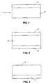
- FIG. 1 of the accompanying drawingsthere is schematically shown a first form of spectacle lens 1 which is made by the method of moulding of the present invention.
- the lens represented in the schematic diagram of Figure 1comprises:
- FIG. 2 of the accompanying drawingsthere is schematically shown a second form of spectacle lens 1 which is made by the method of moulding of the present invention.
- the lens represented in the schematic diagram of Figure 2is of sandwich-like construction and comprises:
- the two layered sections 5are formed so that one of them covers the front surface of the central section 4 and the other covers the back surface of the central section 4. In this way, the lens is formed in a sandwich-type construction.
- FIG. 3 of the accompanying drawingsthere is schematically shown a third form of spectacle lens 1 made by the method of moulding of the present invention.
- the lens represented in the schematic diagram of Figure 3comprises:
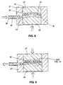
- the moulding operationis a combined injection/compression moulding process specifically intended for the production of ophthalmic lenses.
- the moulding operationinvolves the use of a device which has a sleeve 21 with a cylindrical bore 22 extending therethrough.
- An injection port 24extends through the wall of the sleeve 21 to the bore 22 and the exterior end of this port 24 is dimensioned and adapted so as to releasably engage an injector nipple 26 of a standard screw injector, the details of which will be known to the industry.
- the bore 22is also provided with an annular groove 23 spaced axially from the injection port 24.
- a pair of moulding dies 27 and 28are also provided, the dies having cylindrical outer surfaces dimensioned to be received in the bore 22 with minimal clearance to allow sliding translation thereof in the bore.
- the die 27is provided with a concave optical quality casting surface 29
- die 28is provided with a convex optical quality casting surface 30.
- the die surfaces 29 and 30 when the dies are located in the sleeve 21define a moulding cavity 31.
- the dies 27 and 28are heated to a temperature slightly above the glass transition temperature of the thermoplastic material being moulded.
- the glass transition temperature Tgis approximately 149°C (300°F) and the dies are heated to approximately 204°C (400°F).
- the sleeve 21is also heated but to a temperature approximately 28°C (50°F) cooler than the dies, so that as a moulding operation is carried out, the injected material will cool and solidify at the outer annular boundary of the moulding cavity 31, and will not extrude into the narrow annular clearance space between the dies and the bore 22.
- the heated diesare assembled in the bore of the heated sleeve 21, and the injector nipple 26 is engaged with the injector port 24.
- Thermoplastic material 32 heated to a viscous, flowable stateis then injected under high pressure into the mould cavity 32 to fill the entire cavity.
- the diesare translated together relative to each other. This step acts to reduce the thickness of the moulding cavity 31 to a desired dimension of the finished lens, and also to squeeze the thermoplastic material in the moulding cavity so that excess material is driven from the moulding cavity 31 out through the injector port, as shown in Figure 2. It may be appreciated that the process is thus self-adjusting in the volume of plastic melt material consumed, so that plastic is not wasted.
- the mould dies 27 and 28are translated conjointly axially in the bore relative to the sleeve, so that the moulding cavity 31 is effectively translated in the bore.
- This actionhas the effect of uncoupling the moulding cavity 31 from the injector port 24, as shown in Figure 3, thereby sealing the moulding cavity 31 and preventing further ejection of plastic material from the moulding cavity.
- the moulding cavity 32is shifted axially so that it is positioned to register with an incorporated the annular groove 23 therein, and the pressurized plastic melt will flow into the groove 23.
- the injector nipple 26may be disengaged from the injector port 24.
- compressive pressureis applied to the dies.
- This compressive pressureis within the range of approximately 3.45x10 6 - 6.89x10 7 N/m 2 (500-10,000 psi), and a pressure of 6.89x10 6 N/m 2 (1000 psi) is typical.
- the assembled mold dies and sleeveare then cooled, either passively by conduction and radiation, or by active cooling means such as cool air jets, conduction heat sinks or the like.
- thermoplastic materialloses heat and cools below the glass transition temperature, forming a solid article.
- the compressive forceis removed from the mould dies 27 and 28.
- a tensile forceis then applied to separate the dies axially and pull one of the dies from the bore 22. Due to the fact that the article 33 extends into the annular groove 23, the article 33 is retained with one of the dies.
- the mould die which was removed from the assemblyis now replaced with a new mould die, which means a new moulding cavity 31B is defined. The components of the assembly are returned to the appropriate temperature.
- the injector nipple 26is engaged again with the injector port 24.
- Thermoplastic material 32 containing an active material heated to viscous, flowable stateis then injected under pressure into the moulding cavity 31B to fill the entire cavity.
- the diesare translated together relative to each other. Thereafter, the mould dies are translated conjointly axially in the bore relative to the sleeve so that the moulding cavity 31B is effectively translated in the bore. This action has the effect of uncoupling the moulding cavity 31B from the injector port 24, thereby sealing the mould cavity and preventing further ejection of plastic material from the mould cavity.
- the moulding cavity 31Bis shifted axially so that it is positioned to register with and incorporated the annual groove 23 therein, and the pressurized plastic melt will flow into the groove 23.
- the injector nipple 26may be disengaged from the injector port 23.
- thermoplastic materialloses heat and cools below the glass transition temperature, forming a solid lens.
- the compressive forceis removed from the mould dies.
- a tensile forceis then applied to separate the dies axially and pull the dies from the bore 22. Due to the fact that the lens 33 extends into the annular groove 23, the lens 33 is retained at the location of its formation while the dies are separated from the lens and translated divergently outwardly from the bore. As the sleeve 21 and the lens 33 cool further, the thermal expansion of the bore and the contraction of the lens will cause the release of the lens from the annular groove 23, and the lens may easily be removed from the bore.
- the methodcan simply be adapted for the production of articles with any number of layers. This is achieved by repeating the replacement/changing of the mould die to form a new mould cavity until the required number of layers have been formed in the article.
Landscapes
- Engineering & Computer Science (AREA)
- Manufacturing & Machinery (AREA)
- Mechanical Engineering (AREA)
- Health & Medical Sciences (AREA)
- Ophthalmology & Optometry (AREA)
- Physics & Mathematics (AREA)
- General Physics & Mathematics (AREA)
- Optics & Photonics (AREA)
- Casting Or Compression Moulding Of Plastics Or The Like (AREA)
- Eyeglasses (AREA)
Abstract
Description
- (for example Polycarbonate)
- $5.50/kg ($2.50/lb)
- (for example Polycarbonate)
- $88.00/kg ($40.00/lb)
- a
layered section 2 which is in effect the main body section ofthe spectacle lens, and which is formed from a basic opticalquality thermoplastic material, for example, a Polycarbonate;and - a
layered section 3 which is moulded over one surface, the frontsurface, of thelayered section 2 and which comprises an opticalquality thermoplastic material which is loaded with an activephotochromic material and is of uniformthickness.
- a
central section 4 which is formed from an optical qualitythermoplastic material; and - two
layered sections 5 formed from an optical qualitythermoplastic material which contains an active material witheach being of uniform thickness.
- a
layered section 6 which is in effect the main body of thespectacle lens 1 and is formed from a basic optical qualitythermoplastic material; and - a
layered section 7 which is moulded over one surface, the rearsurface of thelayered section 6 and which comprises an optically clear quality thermoplastic material which is loadedwith an active material and is of uniform thickness.
Claims (6)
- A method of making a layered photochromic spectacle lens from thermoplasticmaterial at least some of which is loaded with an active photochromic material, themethod comprising:introducing a thermoplastic material (32) in a flowable state into a mould cavity(31) defined by mould components (27,28);cooling the thermoplastic material (32) below the glass transition temperature sothat one layer of the lens (33) is formed;separating one of the mould components (28) from that one layer of the lens (33);introducing a thermoplastic material (32) in a flowable state into a second mouldcavity (31B) defined by a mould component (28) and the said one layer of the lens (33)to establish a second layer of the lens (33); andcooling the thermoplastic material (32) to form a photochromic ophthalmicsubstantially homogenous, layered product having no distinct phase boundary.
- The method of claim 1, wherein one of the layers of the lens (33) containsphotochromic material and is formed of uniform thickness.
- The method of claim 2, wherein in addition to said layer of uniform thickness,other layers containing materials selected from the group consisting of photochromicmaterial, ultraviolet absorbing material, and a property modifier, are formed.
- The method of claim 1 wherein more than one layer of adjacent photochromicloaded layers are formed, and the combination of layers appears to alter the colourproduced on the photochromic activation.
- The method of claim 1 wherein said one layer and said second layer aresubstantially identical except for the presence of said active photochromic material in oneof them.
- The method of claim 1 wherein the second layer is loaded with said activephotochromic material.
Applications Claiming Priority (3)
| Application Number | Priority Date | Filing Date | Title |
|---|---|---|---|
| US08/049,798US5405557A (en) | 1993-04-21 | 1993-04-21 | Method of making a moulded photochromic lens |
| US49798 | 1993-04-21 | ||
| PCT/US1994/004233WO1994023929A1 (en) | 1993-04-21 | 1994-04-18 | Moulded photochromic lens and method of making same |
Publications (2)
| Publication Number | Publication Date |
|---|---|
| EP0696955A1 EP0696955A1 (en) | 1996-02-21 |
| EP0696955B1true EP0696955B1 (en) | 1998-07-15 |
Family
ID=21961804
Family Applications (2)
| Application Number | Title | Priority Date | Filing Date |
|---|---|---|---|
| EP94913424AExpired - LifetimeEP0696955B1 (en) | 1993-04-21 | 1994-04-18 | Moulded photochromic lens and method of making same |
| EP94914818AExpired - LifetimeEP0695231B1 (en) | 1993-04-21 | 1994-04-18 | Moulded photochromic lens and method of making same |
Family Applications After (1)
| Application Number | Title | Priority Date | Filing Date |
|---|---|---|---|
| EP94914818AExpired - LifetimeEP0695231B1 (en) | 1993-04-21 | 1994-04-18 | Moulded photochromic lens and method of making same |
Country Status (5)
| Country | Link |
|---|---|
| US (2) | US5405557A (en) |
| EP (2) | EP0696955B1 (en) |
| AU (2) | AU678006B2 (en) |
| DE (2) | DE69411721T2 (en) |
| WO (2) | WO1994023929A1 (en) |
Cited By (1)
| Publication number | Priority date | Publication date | Assignee | Title |
|---|---|---|---|---|
| DE102008034153A1 (en) | 2008-07-22 | 2010-01-28 | Engel Austria Gmbh | Method for producing optical element, particularly prisms and optical lens by injecting plasticized plastic into mold cavity, involves injecting plastic mass in base body and injecting another plastic mass in base body |
Families Citing this family (63)
| Publication number | Priority date | Publication date | Assignee | Title |
|---|---|---|---|---|
| US5405557A (en)* | 1993-04-21 | 1995-04-11 | Sola Group Ltd. | Method of making a moulded photochromic lens |
| JP2908176B2 (en)* | 1993-05-18 | 1999-06-21 | 株式会社小糸製作所 | Synthetic resin laminated lens for vehicle lighting and molding method thereof |
| JP3358277B2 (en) | 1994-03-28 | 2002-12-16 | 住友化学工業株式会社 | Method for producing multilayer molded body |
| AUPN007194A0 (en)* | 1994-12-16 | 1995-01-19 | Sola International Holdings Ltd | Method of preparing photochromic article |
| AU704802B2 (en)* | 1994-12-16 | 1999-05-06 | Carl Zeiss Vision Australia Holdings Ltd | Method of preparing photochromic article |
| US5733483A (en)* | 1995-01-13 | 1998-03-31 | Soane Technologies, Inc. | Method for formation of on-site coated and tinted optical elements |
| US5757459A (en)* | 1995-03-03 | 1998-05-26 | Vision-Ease Lens, Inc. | Multifocal optical elements |
| US7048997B2 (en)* | 1995-03-03 | 2006-05-23 | Vision-Ease Lens | Production of optical elements |
| US5730911A (en)* | 1995-03-03 | 1998-03-24 | Essilor International-Compagnie General D'optique | Process for the manufacture of a substrate made of transparent organic glass and substrate thus obtained |
| AUPN718195A0 (en)* | 1995-12-18 | 1996-01-18 | Sola International Holdings Ltd | Laminate wafers |
| US5928682A (en)* | 1995-12-21 | 1999-07-27 | Johnson & Johnson Vision Products, Inc. | Annular gated mold for the injection molding of contact lenses |
| JP3260072B2 (en)* | 1996-04-05 | 2002-02-25 | ホーヤ株式会社 | Injection compression molding method for lenses |
| US5789015A (en)* | 1996-06-26 | 1998-08-04 | Innotech, Inc. | Impregnation of plastic substrates with photochromic additives |
| US5800744A (en)* | 1996-08-13 | 1998-09-01 | Munakata; Yoshikazu | Method for producing a dioptric photocromic semi-finished lens |
| US5922250A (en)* | 1996-11-05 | 1999-07-13 | Bridgestone Corporation | Method of manufacturing optical-use plastic products |
| US5914174A (en)* | 1996-12-05 | 1999-06-22 | Innotech, Inc. | Lens or semi-finished blank comprising photochromic resin compositions |
| EP1009581A4 (en)* | 1997-02-20 | 2004-07-28 | Technology Resource Int Corp | Method and apparatus for assembling lens-forming device |
| US6103148A (en)* | 1998-02-19 | 2000-08-15 | Technology Resources International Corporation | Method for curing a lens-forming fluid |
| US6936197B1 (en) | 1998-07-24 | 2005-08-30 | Duane L. Wires | Method and compositions for manufacturing coated photochromatic articles |
| CN1311732A (en)* | 1998-07-24 | 2001-09-05 | 光学模制系统公司 | Method and composition for making article with photochromic coating |
| US6159397A (en)* | 1998-11-18 | 2000-12-12 | Eyecity.Com, Inc. | Translucent eyewear lenses and method of manufacture therefor |
| US6068797A (en)* | 1998-12-11 | 2000-05-30 | Ppg Industries Ohio, Inc. | Method of preparing a shaped article having a photochromic coating thereon |
| USD434050S (en)* | 1999-12-06 | 2000-11-21 | Technology Resource International Corporation | Gasket for lens making |
| WO2001043953A1 (en)* | 1999-12-15 | 2001-06-21 | Bausch & Lomb Incorporated | Method of molding lenses |
| US7077985B2 (en)* | 2000-05-30 | 2006-07-18 | Vision-Ease Lens | Injection molding of lens |
| EP1337395B1 (en)* | 2000-11-29 | 2006-08-23 | Zms, Llc | Photochromic articles and methods for making them |
| US20040131872A1 (en)* | 2001-11-29 | 2004-07-08 | Shaobin Fan | Photochromic articles and methods for making them |
| AUPR949201A0 (en)* | 2001-12-14 | 2002-01-24 | Sola International Holdings Ltd | Photochromic coating process |
| US8012386B2 (en)* | 2002-05-02 | 2011-09-06 | Bnl Eurolens | Method of manufacturing a lens presenting a graded tint |
| FR2839276B1 (en)* | 2002-05-02 | 2004-06-18 | Bnl Eurolens | METHOD FOR MANUFACTURING A LENS HAVING A TINT WITH DEGRADE |
| US6863848B2 (en) | 2002-08-30 | 2005-03-08 | Signet Armorlite, Inc. | Methods for preparing composite photochromic ophthalmic lenses |
| DE60226180T2 (en)* | 2002-08-30 | 2009-06-18 | Signet Armorlite, Inc., San Marcos | METHOD FOR THE PRODUCTION OF PHOTOCHROMIC OPHTHALMIC COMPOSITE LENSES AND A PHOTOCHROMIC LENS |
| US6863844B2 (en)* | 2002-08-30 | 2005-03-08 | Signet Armorlite, Inc. | Photochromic matrix compositions for use in ophthalmic lenses |
| US7465414B2 (en)* | 2002-11-14 | 2008-12-16 | Transitions Optical, Inc. | Photochromic article |
| US7858001B2 (en)* | 2003-09-09 | 2010-12-28 | Insight Equity A.P.X., L.P. | Photochromic lens |
| US8298671B2 (en) | 2003-09-09 | 2012-10-30 | Insight Equity, A.P.X, LP | Photochromic polyurethane laminate |
| FR2861640B1 (en)* | 2003-10-29 | 2007-06-08 | Bnl Eurolens | METHOD AND DEVICE FOR MANUFACTURING DEGRADED TINT LENS |
| CA2457266A1 (en)* | 2004-02-11 | 2005-08-11 | Dbm Reflex Enterprises Inc. | Injection process for large-sized retroreflecting prisms |
| ES2599311T3 (en)* | 2005-03-01 | 2017-02-01 | Carl Zeiss Vision Australia Holdings Ltd. | Coatings for ophthalmic lens elements |
| EP1874984A2 (en) | 2005-03-04 | 2008-01-09 | Vision-Ease Lens, Inc. | Forming method for polymeric laminated wafers comprising different film materials |
| DE102005022860A1 (en)* | 2005-05-18 | 2006-11-23 | Rodenstock Gmbh | Method for producing a photochromic plastic article |
| US7258437B2 (en)* | 2005-09-07 | 2007-08-21 | Transitions Optical, Inc. | Photochromic multifocal optical article |
| DE102005053979A1 (en)* | 2005-11-11 | 2007-05-24 | Wilhelm Weber Gmbh & Co. Kg | Method and plastic injection device for producing a light guide body |
| US7833442B2 (en)* | 2005-12-21 | 2010-11-16 | Essilor International (Compagnie Generale D'optique) | Method for coating an ophthalmic lens within an injection molding machine |
| ES2407821T3 (en)* | 2006-05-09 | 2013-06-14 | Carl Zeiss Vision Australia Holdings Ltd. | Methods for forming high index coated optical elements |
| DE202007018847U1 (en)* | 2007-03-06 | 2009-06-25 | Jenoptik Polymer Systems Gmbh | Device for producing thick-walled optical plastic molded parts and thick-walled optical plastic molded part |
| WO2008135268A1 (en)* | 2007-05-04 | 2008-11-13 | Intercast Europe S.R.L. | Method for manufacturing an optical element made of thermosetting plastic material for use in eye-protecting devices and optical element thus obtained |
| US7820082B2 (en)* | 2007-06-20 | 2010-10-26 | Essilor International (Compagne Generale D'optique) | Method for adding a thermoset overmold layer to a lens within a mold |
| US7922942B2 (en)* | 2008-12-05 | 2011-04-12 | Essilor International (Compagnie Generale D'optique) | Injection mold design, method for in-mold coating of lenses, and coated lenses |
| KR101847658B1 (en)* | 2010-02-01 | 2018-05-24 | 디비엠 리플렉스 엔터프라이즈스 인크. | Thick lens molded with embedded layers of the same resin using a two step injection molding process |
| US8891171B2 (en) | 2010-02-01 | 2014-11-18 | Dbm Reflex Enterprises Inc. | High sag thick lens for use in an illumination apparatus |
| KR101954462B1 (en) | 2010-11-24 | 2019-03-05 | 코베스트로 도이칠란드 아게 | Method for producing molded optical parts |
| JP5836610B2 (en)* | 2011-03-04 | 2015-12-24 | キヤノン株式会社 | Plastic optical member and manufacturing method thereof |
| US9242418B2 (en)* | 2011-11-16 | 2016-01-26 | Essilor International | Ophthalmic lens containing a fresnel surface and method for manufacturing same |
| JP5731359B2 (en)* | 2011-11-18 | 2015-06-10 | 南部化成株式会社 | Multilayer molded article and optical lens |
| KR20130111762A (en)* | 2012-04-02 | 2013-10-11 | 삼성전자주식회사 | Lens and fabrication method thereof |
| JP6429434B2 (en)* | 2012-05-23 | 2018-11-28 | キヤノン株式会社 | Plastic optical member and manufacturing method thereof |
| DE102012022277B4 (en)* | 2012-11-14 | 2024-07-18 | Volkswagen Aktiengesellschaft | Lighting device with a light disc and method for producing a light disc for a lighting device |
| WO2015017929A1 (en) | 2013-08-05 | 2015-02-12 | Dbm Reflex Enterprises Inc. | Injection molding device for thick lenses and method of manufacturing |
| JP5873584B1 (en)* | 2015-03-12 | 2016-03-01 | 株式会社ホプニック研究所 | Plastic lens manufacturing method, film positioning method |
| US9733488B2 (en) | 2015-11-16 | 2017-08-15 | Younger Mfg. Co. | Composite constructed optical lens |
| US10934480B2 (en)* | 2017-03-01 | 2021-03-02 | Younger Mfg. Co. | Optical articles comprising photochromic poly(urea-urethane) |
| JP6949746B2 (en)* | 2018-01-31 | 2021-10-13 | 住友重機械工業株式会社 | Injection molding method and mold equipment |
Family Cites Families (20)
| Publication number | Priority date | Publication date | Assignee | Title |
|---|---|---|---|---|
| CA735781A (en)* | 1966-06-07 | C. Tatum John | Two-color shuttle mold | |
| US2635289A (en)* | 1945-11-16 | 1953-04-21 | Freeman H Owens | Method and means for producing optical and other precision elements and the products thereof |
| US3363039A (en)* | 1963-08-09 | 1968-01-09 | Asahi Dow Ltd | Injection molding processes for thermoplastic materials |
| US3716489A (en)* | 1970-10-02 | 1973-02-13 | American Cyanamid Co | Supersaturated solid solutions of photochromic materials in epoxies |
| US3822107A (en)* | 1970-11-20 | 1974-07-02 | Engel Kg L | Improvements in or relating to an injection mold |
| US4076788A (en)* | 1976-12-02 | 1978-02-28 | General Motors Corporation | Mold coating of freshly molded articles |
| US4758448A (en)* | 1982-09-07 | 1988-07-19 | Signet Armorlite, Inc. | Coated ophthalmic lenses and method for coating the same |
| JPH0764033B2 (en)* | 1983-09-07 | 1995-07-12 | ミノルタ株式会社 | Junction type optical member and manufacturing method thereof |
| AU564689B2 (en)* | 1985-07-09 | 1987-08-20 | Kureha Kagaku Kogyo K.K. | Photochromic lens |
| US4836960A (en)* | 1987-10-05 | 1989-06-06 | Sola Usa, Inc. | Fabrication of thermoplastic optical components by injection/compression molding |
| US5147585A (en)* | 1987-10-30 | 1992-09-15 | Blum Ronald D | Method for forming plastic optical quality spectacle lenses |
| US5219497A (en)* | 1987-10-30 | 1993-06-15 | Innotech, Inc. | Method for manufacturing lenses using thin coatings |
| US4919850A (en)* | 1988-05-06 | 1990-04-24 | Blum Ronald D | Method for curing plastic lenses |
| US4873029A (en)* | 1987-10-30 | 1989-10-10 | Blum Ronald D | Method for manufacturing lenses |
| JPH0548315Y2 (en)* | 1988-03-25 | 1993-12-22 | ||
| EP0476228A1 (en)* | 1990-08-20 | 1992-03-25 | Bridgestone Corporation | Reflector and method of and apparatus for fabricating the same |
| US5170192A (en)* | 1990-11-29 | 1992-12-08 | Pilkington Visioncare, Inc. | Oxygen permeable bifocal contact lenses and their manufacture |
| DE4220251C2 (en)* | 1991-06-20 | 1996-10-17 | Rodenstock Optik G | Photochromic plastic optical element |
| US5405557A (en)* | 1993-04-21 | 1995-04-11 | Sola Group Ltd. | Method of making a moulded photochromic lens |
| RU2150388C1 (en)* | 1993-12-10 | 2000-06-10 | Иннотек, Инк. | Method of manufacturing photochromic composite plastic lenses (versions), composite plastic optical lens |
- 1993
- 1993-04-21USUS08/049,798patent/US5405557A/ennot_activeExpired - Lifetime
- 1994
- 1994-03-10USUS08/208,235patent/US5523030A/ennot_activeExpired - Lifetime
- 1994-04-18AUAU65594/94Apatent/AU678006B2/ennot_activeCeased
- 1994-04-18DEDE69411721Tpatent/DE69411721T2/ennot_activeExpired - Lifetime
- 1994-04-18WOPCT/US1994/004233patent/WO1994023929A1/enactiveIP Right Grant
- 1994-04-18WOPCT/US1994/004225patent/WO1994023928A1/enactiveIP Right Grant
- 1994-04-18DEDE69411728Tpatent/DE69411728T2/ennot_activeExpired - Lifetime
- 1994-04-18EPEP94913424Apatent/EP0696955B1/ennot_activeExpired - Lifetime
- 1994-04-18AUAU67066/94Apatent/AU678578B2/ennot_activeExpired
- 1994-04-18EPEP94914818Apatent/EP0695231B1/ennot_activeExpired - Lifetime
Cited By (2)
| Publication number | Priority date | Publication date | Assignee | Title |
|---|---|---|---|---|
| DE102008034153A1 (en) | 2008-07-22 | 2010-01-28 | Engel Austria Gmbh | Method for producing optical element, particularly prisms and optical lens by injecting plasticized plastic into mold cavity, involves injecting plastic mass in base body and injecting another plastic mass in base body |
| DE102008034153C5 (en) | 2008-07-22 | 2023-07-06 | Engel Austria Gmbh | Method of manufacturing optical lenses |
Also Published As
| Publication number | Publication date |
|---|---|
| DE69411728T2 (en) | 1999-03-18 |
| US5523030A (en) | 1996-06-04 |
| EP0695231B1 (en) | 1998-07-15 |
| AU678006B2 (en) | 1997-05-15 |
| DE69411721D1 (en) | 1998-08-20 |
| WO1994023929A1 (en) | 1994-10-27 |
| DE69411721T2 (en) | 1999-04-15 |
| AU6706694A (en) | 1994-11-08 |
| DE69411728D1 (en) | 1998-08-20 |
| EP0695231A1 (en) | 1996-02-07 |
| AU678578B2 (en) | 1997-06-05 |
| WO1994023928A1 (en) | 1994-10-27 |
| EP0696955A1 (en) | 1996-02-21 |
| US5405557A (en) | 1995-04-11 |
| AU6559494A (en) | 1994-11-08 |
Similar Documents
| Publication | Publication Date | Title |
|---|---|---|
| EP0696955B1 (en) | Moulded photochromic lens and method of making same | |
| US6638450B2 (en) | Method for manufacturing an injection molded thermoplastic ophthalmic lens having an encapsulated light polarizing element | |
| US3363039A (en) | Injection molding processes for thermoplastic materials | |
| CA1142309A (en) | Mold apparatus | |
| US5415817A (en) | Process for molding plastic lenses | |
| US5776381A (en) | Process and apparatus for the production of optical lenses | |
| WO2012132597A1 (en) | Die device for multilayer molding and multilayer molded article | |
| JPS6119407B2 (en) | ||
| JP2002539985A (en) | Casting method for producing thin thermoplastic lenses | |
| EP0475431B1 (en) | Method of manufacturing thermoplastic-resin molded optical member | |
| US5700416A (en) | Press molding of thermoplastic resins | |
| JPH08187793A (en) | Plastic optical member and production thereof | |
| JPH03502908A (en) | Disposable optical mold manufacturing method and device | |
| JPH0331124B2 (en) | ||
| WO2000051805A1 (en) | Injection moulding device and method for preparing precision-optical and precision-mechanical parts from a thermoplastic | |
| CN102039770A (en) | Decorative film and in-mold decoration molding process | |
| JPH06238711A (en) | Injection molding method and device for plastic | |
| JP6344408B2 (en) | Molding method of resin molded products | |
| JPS61229520A (en) | Injection compression mold equipment for multiple molds | |
| EP0614741A1 (en) | Improved injection molded product and method | |
| JP3444515B2 (en) | Optical element molding method | |
| JPH05169488A (en) | Manufacturing method of lamp lens for vehicle | |
| JP2999109B2 (en) | Optical disk manufacturing equipment | |
| JP2585847Y2 (en) | Injection mold | |
| JPS6064821A (en) | Injection molding apparatus |
Legal Events
| Date | Code | Title | Description |
|---|---|---|---|
| PUAI | Public reference made under article 153(3) epc to a published international application that has entered the european phase | Free format text:ORIGINAL CODE: 0009012 | |
| 17P | Request for examination filed | Effective date:19951018 | |
| AK | Designated contracting states | Kind code of ref document:A1 Designated state(s):BE DE ES FR GB IE IT NL | |
| 17Q | First examination report despatched | Effective date:19970416 | |
| GRAG | Despatch of communication of intention to grant | Free format text:ORIGINAL CODE: EPIDOS AGRA | |
| GRAG | Despatch of communication of intention to grant | Free format text:ORIGINAL CODE: EPIDOS AGRA | |
| GRAH | Despatch of communication of intention to grant a patent | Free format text:ORIGINAL CODE: EPIDOS IGRA | |
| GRAH | Despatch of communication of intention to grant a patent | Free format text:ORIGINAL CODE: EPIDOS IGRA | |
| GRAA | (expected) grant | Free format text:ORIGINAL CODE: 0009210 | |
| AK | Designated contracting states | Kind code of ref document:B1 Designated state(s):BE DE ES FR GB IE IT NL | |
| PG25 | Lapsed in a contracting state [announced via postgrant information from national office to epo] | Ref country code:NL Free format text:LAPSE BECAUSE OF FAILURE TO SUBMIT A TRANSLATION OF THE DESCRIPTION OR TO PAY THE FEE WITHIN THE PRESCRIBED TIME-LIMIT Effective date:19980715 Ref country code:IT Free format text:LAPSE BECAUSE OF FAILURE TO SUBMIT A TRANSLATION OF THE DESCRIPTION OR TO PAY THE FEE WITHIN THE PRE;WARNING: LAPSES OF ITALIAN PATENTS WITH EFFECTIVE DATE BEFORE 2007 MAY HAVE OCCURRED AT ANY TIME BEFORE 2007. THE CORRECT EFFECTIVE DATE MAY BE DIFFERENT FROM THE ONE RECORDED.SCRIBED TIME-LIMIT Effective date:19980715 Ref country code:ES Free format text:THE PATENT HAS BEEN ANNULLED BY A DECISION OF A NATIONAL AUTHORITY Effective date:19980715 Ref country code:BE Free format text:LAPSE BECAUSE OF FAILURE TO SUBMIT A TRANSLATION OF THE DESCRIPTION OR TO PAY THE FEE WITHIN THE PRESCRIBED TIME-LIMIT Effective date:19980715 | |
| REF | Corresponds to: | Ref document number:69411728 Country of ref document:DE Date of ref document:19980820 | |
| ET | Fr: translation filed | ||
| REG | Reference to a national code | Ref country code:IE Ref legal event code:FG4D | |
| NLV1 | Nl: lapsed or annulled due to failure to fulfill the requirements of art. 29p and 29m of the patents act | ||
| PLBE | No opposition filed within time limit | Free format text:ORIGINAL CODE: 0009261 | |
| STAA | Information on the status of an ep patent application or granted ep patent | Free format text:STATUS: NO OPPOSITION FILED WITHIN TIME LIMIT | |
| 26N | No opposition filed | ||
| REG | Reference to a national code | Ref country code:GB Ref legal event code:IF02 | |
| PGFP | Annual fee paid to national office [announced via postgrant information from national office to epo] | Ref country code:FR Payment date:20110210 Year of fee payment:18 | |
| PGFP | Annual fee paid to national office [announced via postgrant information from national office to epo] | Ref country code:GB Payment date:20110302 Year of fee payment:18 Ref country code:IE Payment date:20110428 Year of fee payment:18 | |
| PGFP | Annual fee paid to national office [announced via postgrant information from national office to epo] | Ref country code:DE Payment date:20110530 Year of fee payment:18 | |
| GBPC | Gb: european patent ceased through non-payment of renewal fee | Effective date:20120418 | |
| REG | Reference to a national code | Ref country code:IE Ref legal event code:MM4A | |
| REG | Reference to a national code | Ref country code:FR Ref legal event code:ST Effective date:20121228 | |
| PG25 | Lapsed in a contracting state [announced via postgrant information from national office to epo] | Ref country code:GB Free format text:LAPSE BECAUSE OF NON-PAYMENT OF DUE FEES Effective date:20120418 Ref country code:IE Free format text:LAPSE BECAUSE OF NON-PAYMENT OF DUE FEES Effective date:20120418 | |
| PG25 | Lapsed in a contracting state [announced via postgrant information from national office to epo] | Ref country code:FR Free format text:LAPSE BECAUSE OF NON-PAYMENT OF DUE FEES Effective date:20120430 | |
| REG | Reference to a national code | Ref country code:DE Ref legal event code:R119 Ref document number:69411728 Country of ref document:DE Effective date:20121101 | |
| PG25 | Lapsed in a contracting state [announced via postgrant information from national office to epo] | Ref country code:DE Free format text:LAPSE BECAUSE OF NON-PAYMENT OF DUE FEES Effective date:20121101 |